1
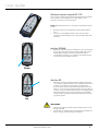
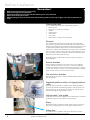
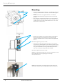
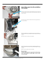
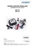
Windlass Systems is rd th a p bo ee n K lo ua an m Installation and user manual Rev4.3 ! Mini 101 Midi 201 SLEIPNER MOTOR AS P.O. Box 519 N-1612 Fredrikstad Norway Tel:+47 69 30 00 60 Fax:+47 69 30 00 70 www.side-power.com [email protected] Made in Norway EN Side-Power MINI101 & MIDI201 © Sleipner Motor AS 2015 Content Introduction of Mini and Midi series..............................................................................................................................................................3 User guide..........................................................................................................................................................................................................4 Before installation..............................................................................................................................................................................................6 Dimensions........................................................................................................................................................................................................7 Installation .........................................................................................................................................................................................................8 Mounting Mini/Midi.........................................................................................................................................................................................8 Insert the rope into the line wheel..................................................................................................................................................................9 Rope around the line wheel......................................................................................................................................................................... 10 Minimum clearance and height under the windlass................................................................................................................................. 11 Installation of stop ring for auto stop.......................................................................................................................................................... 12 Wiring diagram...............................................................................................................................................................................................13 Electrical installation...................................................................................................................................................................................... 14 Electrical wiring.............................................................................................................................................................................................. 14 Installation of control unit 150800............................................................................................................................................................... 15 Main switch/miniature circuit breaker......................................................................................................................................................... 16 Maintenance and service.............................................................................................................................................................................. 17 Technical data................................................................................................................................................................................................ 18 Troubleshooting............................................................................................................................................................................................. 19 2 SP Mini Midi Rev4.3 2015 Introduction Congratulations on your new windlass and thank you for selecting a Side-Power windlass. We hope your windlass will meet your expectations. Please note that this requires that the windlass will be installed and used in accordance with this manual in an environment with the correct conditions for proper operations. This includes the necessary voltage capacity for the windlass motor as well as correct placement of windlass, rope, anchor and anchor bracket. Introduction of MINI 101 and MIDI 201 Side-Power Engbo MINI 101 is designed for boats up to approximately 20 feet and Engbo MIDI 201 is designed for boats up to approximately 25 feet. These windlasses are true free-fall windlasses and are developed with a new electrical control box unit. This new unit is ready for connecting Side-Power remote control and switch panel. IMPORTANT! This manual contains information you need to know before installing the windlass. Therefore, please read it carefully. General procedure for use of Side-Power windlasses Read the operating manual carefully before installing and using the windlass. Please note that strong forces are involved, so please use the windlass carefully and make sure, for example, that: • • • • • • • • • • • • Keep your distance to the windlass, the rope, anchor and anchor brackets during operation Keep the rope/chain under observation during anchor handling. Make sure anyone using the windlass knows how to operate it. Be aware when the anchor are raised as it can bring unwanted debris up from the bottom, potentially damaging your boat. If the windlass is straining as the anchor are raised, stop for a few seconds and let the boat pic up momentum before continuing the raise. If the anchor is stuck, release some rope/chain and attach it to a cleat before using the boat to pull the anchor free. The windlass is not designed for loads beyond the specified pull capabilities. The anchor must always be secured to the boat while sailing. Use the security line or other means to prevent unintentional anchor drop. Turn off the power to the windlass when not in use. Children must not operate the windlass. Careless use can cause damage or injury! Make sure to have good battery capacity, and keep the engine running windlass operation. Sleipner Motor AS is not responsible for injury caused by the use of our windlass systems IMPORTANT! • Always keep the boat’s motor running when operating the windlass. • Always turn off the power to the windlass when it is not operated. • The anchor must always be secured with security line when windlass is not in use. • While dropping anchor, do not push the “UP” button until the anchor is resting at the seabed. • Windlass and accessories must be installed and used in a manner that will not cause damage or injury. • Personnel qualified for high current installations must carry out or check the installation. • Do not mount any windlass parts in hazardous environments (I.e. flammable fumes or gasses). • The control unit is NOT protected from water ingress, it must be installed in a dry area and not exposed for water. SP Mini Midi Rev4.3 2015 3 User guide Docking with remote control 1. 2. 3. 4. 5. Make sure the boat engine is running during anchoring. Decide where you want to drop anchor. Check that the safety line on the anchor has been loosened. Turn ON the main switch of the windlass. When main switch for the windlass has been switched off, you must press down both ON buttons on the remote, before pressing DOWN button to release the anchor. Docking with fixed switch panel 1. 2. 3. 4. Press the down button for at least 1 sec. The anchor will drop. The windlass is now released and the rope will run out in step with the progress of the boat towards land. Tie up the boat Note! If you are using a free-fall chain windlass, the high weight of the chain may result in the full length of the chain being pulled out. If so, make sure to tighten the slack once you have tied up the boat. Note!The windlass will always wind in slowly before it switches to full speed. Departing 1. 2. 3. 4. 5. Start the boat engine to charge the battery. Turn on the main switch. Release the mooring from land. Activate the windlass. Keep the up button depressed, and the windlass will pull the boat away from land. The windlass will pull the anchor up at full speed until the first auto stop is activated. After the first auto stop: 1. 2. 3. 4. 5. 6. Release the up button, press again and keep depressed. The windlass will continue to raise the anchor slowly until the second auto stop is activated, stopping the windlass completely. The anchor will then be correctly seated in the anchor bracket. Attach the safety line to the anchor. Turn off the main switch of the windlass. Have a pleasant sailing! Note! This ONLY applies for rope windlasses and requires the anchor rope to be correctly fitted with brass wire markers. Important! Keep an eye on the anchor when it leaves the water and seats in the anchor bracket. This will allow you to stop the windlass and prevent damage if the anchor pulls up foreign objects from the seabed. Note! If the windlass is straining while raising the anchor, it would be a good idea (and save power) to run the windlass in periods. Once the boat has begun to move backwards, you can release the up button and then run the windlass in periods. 4 SP Mini Midi Rev4.3 2015 User guide Wireless remote control RC-11E The remote is waterproof and floats if dropped into the water. It has under normal conditions an radio range of 15m. See own manual for more information. Note! Remote and receiver is normally connected and ready to use. • • Remote control is turned ON by pressing both ON buttons. To ensure a long battery lifetime, the remote control switches off automatically 4 min. after the last button was pressed. Anchor DOWN • • When the remote control is switched on, you can drop the anchor by pressing the “down” button. Keep this button depressed for at least 1 second to drop the anchor. The windlass will then run out slowly in the beginning to ensure the correct release function. Down Anchor UP • When the anchor has dropped to the seabed, press the “up” button to tighten the slack. The windlass will continue to winch in as long as you keep the “up” button depressed. If the remote control has switched off automatically (i.e. if you have not pressed a button for more than 4 min) you must first switch ON, and then immediately press UP start to wind in the anchor rope/chain. The windlass always starts to operate at reduced speed before increasing to full speed. Up IMPORTANT! • • SP Mini Midi Rev4.3 2015 Always turn OFF the power to the windlass when it is not being operated. The anchor must always be secured to the boat while the boat is sailing. Use the safety line supplied. 5 Before installation • • • • • Remember! Make sure to have all necessary tools ready Unpack and organize all components Prepare and control the areas where all the different parts can be mounted. Follow the mounting instructions When winching the rope for the first time after mounting, make sure the rope is tight, so the rope is pulled inn correctly. Placing the parts You must plan the placement of the following parts: • Winch/motor • Brackets for anchor and windlass • Cables • Switch panel • Controlbox • Line guide • Main switch/ miniature circuit breaker General The windlass should be positioned as high as possible to allow maximum space for the rope that will be stored below the windlass. The height from the bottom of the wall where the rope is stored to the bottom edge of the line wheel should be at least 50 cm, and the area should be at least 40 x 40 cm to allow room for 50 m x 12 mm anchor rope. This will prevent the rope from bunching under the windlass and assure sufficient friction between the line wheel and the rope. Note! Remember to attach the end of the rope somewhere inside the boat. Anchor bracket Fit the windlass so that the rope is wound up in line with the anchor bracket (see pictures 1 and 2) – a numerous different models are available. The anchor bracket is working as a guide for the rope when the anchor is on the seabed and as a “seating point” for the anchor once it has been raised. 1 2 Use of anchor bracket The bracket for the rope must be installed with the rollers outside the platform. Standard platform roller or hinged platform roller If the windlass is fitted low in relation to the bathing platform, so the angle between the bathing platform and the rope is too small ,and if you are using a Bruce anchor, you should use an Side-Power Engbo hinged platform roller. Hull conduit / Line guide It will often be necessary to install a hull conduit with a roller that guides the rope with low friction through the hull. Rope Side-Power Engbo supplies original woven anchor rope with a lead core . It is supplied in various lengths and dimensions. Safety line Once the anchor is seated in the anchor bracket, it must be secured with the safety line supplied. 6 SP Mini Midi Rev4.3 2015 Dimensions SP Mini Midi Rev4.3 2015 7 Installation Mounting • • • • The mounting bracket for MINI 101 and MIDI 201 allows for infinitely variable rotation in relation to the windlass gear/ motor. The bracket for the rope guide/deflector can also be rotated independently of the gear/motor and mounting bracket. This allows for installing the windlass on surfaces with different angles in relation to the stern. It can be fitted on the inside of the stern, hanging below the deck or aft of cross bulkheads inside the boat. Position the windlass mounting bracket by loosening the two screws fastening the bracket to the gear housing, rotate the windlass to the correct position and tighten the screws. Note! Max. tightening torque 17 Nm. • Adjust the windlass rope guide bracket in a corresponding manner by loosening the screw fastening it to the gear house. Rotate the bracket so the rope is guided down and away from bulkheads and components that prevent the rope from coiling correctly below the windlass. Note! Max. tightening torque 17 Nm. NOTE! It is important that the rope is wound sufficiently around the line wheel to ensure a good grip on the rope. See separate section. NOTE! The ”line guide” must be located in centre of the line wheel. Also check this after having tightened the fixing screw. 8 SP Mini Midi Rev4.3 2015 Insert the rope into the windlass line wheel Insert the rope into the line wheel between the line wheel and the rope guide. It may be easier if you bend the tip of the rope guide carefully. Route the rope via the line wheel and out through the hole in the rope deflector. When the windlass is connected, the rope can be pulled by pressing down on the up button on the touch panel or remote control. Note! Be careful to avoid injuring fingers. When the tip of the rope has been pulled through the rope deflector, the rest of the rope can be pulled through using the windlass. Make sure the windlass reels as intended. Remember! When pulling in the rope for the first time, you must keep the rope tight, so the rope run correctly. SP Mini Midi Rev4.3 2015 9 Installation Rope around the line wheel The mounting bracket for MINI 101 and MIDI 201 allows for infinitely variable rotation in relation to the windlass gear/motor. The bracket for the rope guide/deflector can also be rotated independently of the gear/motor and mounting bracket. See separate description. This description is for installation of the windlass on a vertical cross bulkhead, on the inside of the stern, for example. The green broken line indicates the bulkhead that the windlass is fastened to. It is important that the length of rope that is in contact with the line wheel is sufficient to ensure good engagement/friction with the rope. See yellow arrows. Note! Regardless of how the windlass is fastened to the boat, the angle between where the rope enters and leaves the line wheel must be minimum 90 degrees. This illustration indicates the windlass fastened below deck, etc. The windlass mounting bracket has been rotated 90degrees counter-clockwise compared with the illustration above. The rope comes from above and goes down into the line wheel. In this case, the rope guide must be adjusted to ensure the rope is pushed out horizontally from the windlass. This picture shows the windlass installed on the back side of an inboard cross bulkhead. The windlass mounting bracket has been rotated 180degrees counter-clockwise compared with the illustration on top of this page. NOTE! The rope is always pulled into the windlass from the right. This is because of the direction of rotation for the windlass line wheel. NOTE! Make sure there is sufficient room to stow the rope below and next to the windlass. Remember! When pulling in the rope for the first time, you must keep the rope tight, so the rope run correctly. 10 SP Mini Midi Rev4.3 2015 Installation Minimum rope clearance and height under windlass In order for the windlass to function normally, there must be a sufficient volume/height below the windlass for stowing the rope when the anchor is up. This table below shows recommended minimum height (A) below the windlass as well as width (B) and length (C) of the area used for stowing the rope. A Tau dimensjon. A (cm) B (cm) C (cm) 10 mm x 30 m 35 30 30 12 mm x 30 m 35 30 30 12 mm x 50 m 40 35 35 NOTE! In case of installations where the rope is routed horizontally out of the windlass when the anchor is up, the relationship between A, B and C may vary. It is important that there is a sufficient volume to ensure that the rope is not forced into place below the windlass and cannot easily be pulled out by the line wheel. B C Installation of stop ring for auto stop NOTE! Applies to MIDI 201 only Under the rope guide there is an inductive sensor that signals auto stop when the anchor has been lifted all the way up. To activate the detector, two stop rings (included) are fitted on the rope. See procedure below. The outer diameter of the stop ring must be as close to the outer diameter of the rope as possible. This is necessary in order for the inductive detector to be able to detect correctly. In order to place the stop ring at the correct location on the rope, lift the anchor until the thimble eye is 25-50 cm below the rope roller (reel in at slow speed for the last section), and mark the rope with a marker at the location of the inductive sensor. The anchor is then reeled in at low speed to the desired final resting position. Mark the rope once more by the detector and fasten the stop rings by the marks. These stop rings will be exposed to wear by the line wheel, especially during heavy loads, and must therefore be inspected regularly. Replace damaged stop rings if needed. Recommended tools: • Keeper ring pliers • Pliers • Auto stop rings (steel rings enclosed) SP Mini Midi Rev4.3 2015 11 Installation The enclosed steel rings (auto stop rings) are fitted in the locations where the windlass should slow down and then come to a full stop. Mark in advance; see procedure on the previous page. Open the stop rings with the keeper ring plier. Fit the ring over the rope. Use the plier to pull the stop ring into place with the stop ring joint overlapping the opening and the ring fitted thightly around the rope. Force the ends into the rope with the pliers to ensure the stop ring does not slip on the rope. A fitted stop ring should look like this with closed windings and the ends secured inside the rope. Stop ring fitted and fastened tightly to the rope. Fasten the other stop ring in the same manner. 12 SP Mini Midi Rev4.3 2015 Wiring diagram Control unit Control unit Control unit Control unit SP Mini Midi Rev4.3 2015 13 Electrical installation Electrical wiring All kind of wiring and electrical fixing must be done with Main switch/ miniature circuit breaker turned OFF and no battry cables attached. Connecting switch panel 86-08950 or 8608955 • • • • • • • 1 pcs switch panel Cables are optinal and come in various lengths. Cable is a 4-way Side-Power cable that easy can be attached to contact on controlbox unit. The cable must be attached to 150810 contact unit 150810 connection to control unit: Black to terminal VBlue to terminal IN Grey to terminal OUT Red to terminal V+ See wiring diagram or control panel manuals for more details Multiple panels can be fixed to the same control unit. Switch panel 86-00002 1. 2. 3. 4. 5. 6. The panel comes with a self-adhesive surface, but if you prefer, you can use the corner holes to screw it firmly in position. Drill an hole (dia. 18 mm) in the place where the panel is to be fitted. Run the panel cable through the hole. Remove the protection tape from the rear surface of the panel and fix the panel firmly to the surface. Run the cable to the electronic control box. Cut off any surplus cable and strip the ends of the three wires that are to be connected to the terminal clips as described in the connection diagram. (See wiring diagram). Connecting switch panel 86-00002 • • • • • The 3-way cable is connected like this: White to terminal IN Green to terminal OUT Brown to terminal V+ See wiring diagram for details Connecting the auto stop switch Cables are connected like this: 4: Brown (BN) 5: Black (BK) 6: Blue (BU) 14 SP Mini Midi Rev4.3 2015 Electrical installation Fitting control unit 150800 The unit is not water resiststant and must be placed in a dry area close to the windlass motor. Use ring termianls of good quality with the correct size for the selected battery cables. Bolt hole shuld be 6mm. Tighten the teminals to maximum 8 Nm. Pay attention to assemble the terminal spacers and washers in the correct order according to figure 1. The unit has mounts that ensures space between the unit and it’s mounting surface. This to avoid condensation to enter the unit. It also ensures proper ventilation of the enclosure. The control unit must be mounted with the the cables protruding downwards. Connecting the motor and battery cables on Mini/Midi Control unit See control unit manual for configuring and more installation information. Motor for windlass type Mini/Midi is delivered with cables fitted to the motor. • Fit included copper link(A1-A2 LINK) between Terminal A1 and A2. • Connect the red cable from the motor to the Terminal marked D1/M+. • Connect the black cable from the motor to the Terminal marked D2/M-. • Connect supply cable from battery negative to the Terminal marked B-. • Connect supply cable from braker/fuse to the Terminal marked B+. Connect beaker/fuse to battery main switch. • See complete wiring diagram on page 6 for reference. • Tighten all terminals properly, including A1 and A2, with a maximum torque of 8Nm. Over-tightening may damage the terminals. • Leave breaker/fuse disconnected until the installation is completed. SP Mini Midi Rev4.3 2015 15 Electrical installation Main switch/miniature circuit breaker 119-00003(Mini100A), 119-00015(Midi 150A) • • • • • • • MUST be used at all time in this installation Works as both MCB and main switch unit. The unit consists of one battery connection and one AUX connection. This is described on the unit. See wiring diagram for correct connection to to battery and contriol box. Fig 1 shows unit switched ON To switch OFF, press red the button. Fig 2 shows unit switched OFF. To switch ON, move/press pin switch uppwards as shwon on Fig 2. WARNING! Fig1 Wrong, improper use or wrong connection of such high currents components will generate a lot of heat which in worst case can cause fire. OFF button Fig2 16 SP Mini Midi Rev4.3 2015 Maintenance and service Winter storage • • • • • Remove the rope from the windlass before every period of winter storage. Soak it in a mild soap solution overnight. Then wash it in water and rinsing fluid to rinse out all the salt residue and dirt. This will keep the rope flexible for many years. At the same time, check the wire thread auto stop indicators and replace them if necessary. Before winter storage, spray the windlass and all electrical points and connections with a moisture repellent spray. Make sure that the windlass is protected against snow and water during winter storage. Do not wrap the windlass, as this may cause condensation to form during winter storage. It is also a good idea to wash the inside of the rope box and remove seaweed, dirt, etc. Changing battery in the remote control • SP Mini Midi Rev4.3 2015 See own manual 17 Technical data Side-Power MINI 101 Side-Power MIDI 201 Rope Braided lead rope: Dia 12 mm, 30 m Weight: 7.2 kg/12 kg Breaking load: 1600 daN Braided lead rope diameter 12 mm, 30/50 m Weight: 7.2 kg/12 kg Breaking load: 1600 daN Pulling power (Electronically governed) Up to 100 kg Up to 200 kg Pulling speed 15-35m/min aprox 20m/min ved 20kg load 15-30m/min aprox 20m/min ved 30kg load Power consumption 10-150A aprox 50A ved 20kg load 10-200A aprox 40A ved 30kg load No-load current ‹ 0,1A ved 12V ‹ 0,1A ved 12V Recommended fuses 50 A 80 A Recommended min. battery capacity 12V/75 Ah 12V/75 Ah Weight: windlass with motor and cables 8,1kg 9,8kg Weight: electronic unit aprox 1kg aprox 1kg Auto stop function Yes (optional) Yes Recommended anchor/ weight 5-8kg Bruce or plate 7.5-16 kg Bruce, plate or Side-Power Recommended boat size Max. 6.0 m (20 feet) Max. 7.6 m (25 feet) Fitting/mounting See the separate descriptions for the individual models See the separate descriptions for the individual models Standard equipment Windlass and basic mounting parts Windlass and basic mounting parts Supplementary equipment Anchor (Multiple types) Anchor bracket (Multiple types) Mounting brackets Battery cable Lead rope or chain Fuse w/holder Hull conduit for rope or chain Wireless remote control Switch panel Cables Control box unit Anchor (Multiple types) Anchor bracket (Multiple types) Mounting brackets Battery cable Lead rope or chain Fuse w/holder Hull conduit for rope or chain Wireless remote control Switch panel Cables Control box unit Motor output, nom. 12V DC/350W 18 SP Mini Midi Rev4.3 2015 12V DC/600W Troubleshooting Note! Main switch/braker must be disconnected whenever working on the windlass mechanical parts FAULT SYMPTOM FAULT CODES/STATUS SOLUTION Windlass does not operate "Power" LED not lit Check: Main switch/breaker is engaged. Check battery fuses. Visually inspect cables and verify that terminals are tight. Measure battery voltage. "Power" LED lit Turn on panel / remote control (see user manual) See below: Windlass only runs for 0,5 seconds when pressing "IN" None Check control panel connections. Signals for "IN" and "OUT" might be swapped. When pressing "OUT" free fall is not engaged. Or: When pressing "IN", motor is running but gypsy is not turning None Swap motor cables D1 and D2 on the control unit Windlass has poor performance “Low voltage” Voltage has dropped below 9V Check batteries. None Measure battery voltage while operating the windlass. I voltage measure below 11V/22V, allow batteries to charge. If the battery voltage is acceptable, measure voltage on the motor terminals, cable voltage drop should be less than 1V when motor is running. Windlass releases anchor, but do not wind in None Check that end stop sensor is not active (Indicated by "End Stop" LED on control unit or LED built into the sensor.) Check sensor connections on the control unit. Sensor LED should not be lit if no metal object is present in front of it. Windlass wind past endstop None Check that the end stop wire wound around the rope is intact. Pull the rope with end stop wire over the end stop sensor and verify that («End Stop» LED light up) Adjust sensor closer to the rope if neccesary. Windlass releases anchor, but stops immediatly when pressing "IN" None or “Low voltage” If the battery is in poor condition it might measure 12/24V when windlass is not in use and still experince a significant voltage drop when the motor starts (such voltage dips might be diffcult to measure) This type of voltage drops can lead to false triggering of the end stop sensor. Windlass stops during operation “Motor Overload” Current limitation has triggered. This means that the windlass is overloaded. Try again with reduced load. If this fault is triggered while the windlass is lightly loaded, it might indicate a mechanical failure. “Controller Overtemp” The control unit temperature sensor is too warm. Let the controller cool down, and try again. “Motor Overtemp” The motor is too hot. The windlass controller calculates motor temperature depending on load and run time. Let the windlass cool down. “Controller Overload” This fault indicates that the internal protection of the contrroller has triggered. This can be caused by exccessive surrounding temperature and high load “Runtime Exceeded” Signal "OUT" or "IN" have been continuous for more than 5 minutes. This is a protection against possible faulty control signals. Re-activation is possible. Abnormal noise during operation The windlass must be serviced. Windlass operates, but rope is not wound in The rope can slip in the gypsy if the windlass is mounted incorrectly. Anchor is not released The anchor might not release from the bracket if mounted incorrectly. If the windlass still does not work normally after you have tried these procedures, the fault is in the windlass itself. Contact your nearest dealer. SP Mini Midi Rev4.3 2015 19 Worldwide sales and service www.side-power.com SLEIPNER MOTOR AS P.O. Box 519 N-1612 Fredrikstad Norway Tel: +47 69 30 00 60 Fax:+47 69 30 00 70 www.side-power.com [email protected]