1
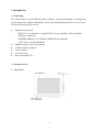
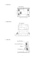
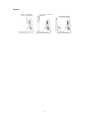
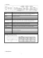
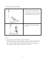
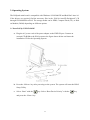
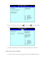
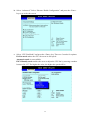
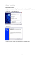
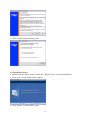
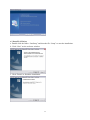
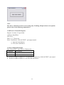
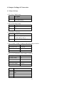
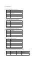
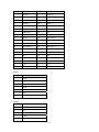
User’s Manual
POSpark 5700 Series
General Information
ABOUT THIS MANUAL
The purpose of this user’s manual is to provide general information on TYSSO POSpark Series
POS terminal and to show the users how to configure the hardware-related configurations. The
information in this manual is subject to change without notice due to rapid improvement on IT
technology. The users can get the most up to date information from our web sites:
http://www.fametech.com.tw
DISCLAIMER
This manual has been examined for accuracy. While precaution has been taken in the
preparation of this manual, neither the manufacturer takes no liability for errors or omissions
nor assume any responsibility for damage(s) incurred directly or indirectly from errors,
omissions, or discrepancies of this manual. IN NO EVENT WILL THE VENDOR BE
LIABLE FOR DIRECT, INDIRECT, SPECIAL, INCIDENTAL, OR CONSEQUENTIAL
DAMAGES ARISING OUT OF THE USE OR INABILITY TO USE THIS PRODUCT OR
DOCUMENTATION, EVEN IF THE POSSIBILITY OF SUCH DAMAGES HAS BEEN
ADVISED. IN PARTICULAR, THE VENDOR SHALL NOT HAVE LIABILITY FOR ANY
HARDWARE, SOFTWARE, OR DATA STORED OR USED WITH THE PRODUCT,
INCLUDING THE COSTS OF REPAIRING, REPLACING, OR RECOVERING SUCH
HARDWARE, SOFTWARE OR DATA.
WARNING
The terminal has been tested and found to comply with the limits for a Class A digital device,
pursuant to Part 15 of the FCC rules. These limits are designed to provide reasonable
protection against harmful interface in a residential installation. This equipment can generate
and radiate radio frequency energy and, if not installed and used according to the instructions,
may cause harmful interference to radio communications. However, there is no guarantee that
interface will not occur under particular installation. If this equipment does cause harmful
interference to radio or television reception, which is found by turning the equipment off and
on, the user is encouraged to try to correct the interface by one or more of the following
measures:
z Reorient or relocate the receiving antenna
z Increase the distance between the equipment or device
z Connect the equipment to an outlet other than the receiver’s
ii
z Consult a dealer or an experienced radio/TV technician for assistance
IMPORTANT NOTICE
CAUTION
The system is provided with a battery-powered Real-Time Clock circuit. There is a danger of
exposing and personal injury if the battery is incorrectly replaced or mistreated. Do not
attempt to disassemble the battery, immerse it in the water or expose it to fire.
WARRANTY LIMITS
If the POSpark series machine is disassembled by any person other than the authorized
technicians, the warranty will be terminated. The users should consult his/her dealer for any
technical problems. Warranty does not cover any damage caused by improper use.
TRADE MARKS AND SERVICE MARKS
TYSSO is a registered trademark of FAMETECH INC.
Other brand and product names are trademarks and registered trademarks and service marks of
their respective owners.
iii
IMPORTANT SAFETY INFORMATION
z
z
z
z
z
z
z
z
z
z
z
z
z
z
z
Read all these instructions carefully.
Use only parts, especially power adapter, recommended by the manufacturer; unapproved
parts may be hazardous.
Before plugging the power cord into the AC inlet of the power supply unit, make sure the
voltage (either 110V or 220V) is properly applied to the power switch. Improper voltage
will cause damage to the power supply unit.
Power off the system and remove the power adapter while cleaning the system.
Before powering on the system, check if all the peripherals are firmly installed.
Do not use the system near water, such as a bathtub, a washbowl, a kitchen sink, a laundry
tub, and a swimming pool. Keep the system away from direct sunlight, a heating or a
radiator.
Do not place the system on an unstable cart, stand or table. If the machine falls, it may
injure a person or cause serious damage to the appliance.
The system is equipped with a three-wire grounded plug with a third (grounding) pin. This
is a safety feature. If your outlet does not accommodate the three-wire plug, have an
electrician install a correct outlet, or use an adapter to ground the appliance safely. Do not
leave out the safety purpose of the grounded plug.
Do not allow anything to rest on the power cord. Do not locate the system where people
may walk on the cord.
Do not make the power outlet and extension cords overload. Overload can result in fire or
electric shock.
Do not push any object into the computer cabinet. Dangerous voltage points may be
touched and the parts may be shorted out resulting in fire or electric shock.
Do not attempt to service the system on your own. Opening or removing cover can expose
you to dangerous voltage or other hazards.
Power off the system before installing or removing non-PNP (plug and play) devices.
If any of the following situations occurs, unplug the systems from the power outlet
immediately and consult with a qualified service person:
1. The power cord or plug is damaged or frayed.
2. Liquid is spilled into the system.
3. The system is dropped or the cabinet is damaged.
When the system is not in use, cover the system and store it with care.
Version 1.0
© Copyright Fametech Inc. (TYSSO) 2008
iv
Contents
General Information ..................................................................................................................ii
ABOUT THIS MANUAL....................................................................................................ii
DISCLAIMER .....................................................................................................................ii
WARNING ...........................................................................................................................ii
IMPORTANT NOTICE ......................................................................................................iii
IMPORTANT SAFETY INFORMATION.......................................................................... iv
1. Introduction ............................................................................................................................ 2
1.1 Unpacking ...................................................................................................................... 2
1.2 System Overview ........................................................................................................... 2
1.3 I/O Ports ......................................................................................................................... 5
1.4 Specifications ................................................................................................................. 5
2. Components & Peripherals Installation............................................................................... 7
2.1 Replace Hard Disk ......................................................................................................... 7
2.2 Install Second Display.................................................................................................... 9
2.3 Install Pole-type Customer Display.............................................................................. 10
3. Operating System ................................................................................................................. 11
3.1 Install OS by USB CD-ROM ....................................................................................... 11
3.2 Adjust CPU Fan Mode and Brightness ........................................................................ 12
4. Drivers Installation .............................................................................................................. 15
4.1 Install Chipset Driver ................................................................................................... 15
4.2 Install Audio Driver...................................................................................................... 16
4.3 Install LAN Driver ....................................................................................................... 17
4.4 Install Touch Screen Driver.......................................................................................... 18
5. Peripherals Testing............................................................................................................... 22
5.1 Magnetic Stripe Card Reader ....................................................................................... 22
5.2 Customer Display......................................................................................................... 23
5.3 Cash Drawer................................................................................................................. 24
6. Jumper Settings & Connectors ........................................................................................... 27
6.1 Jumper Settings ............................................................................................................ 27
6.2 Connectors.................................................................................................................... 28
1
1. Introduction
1.1 Unpacking
The contents may vary with different options. If there’s any physical damage or missing parts,
please contact your supplier immediately. Please keep all packing materials in case you need
to ship back the device for service.
z
z
z
z
z
z
POSpark main system
- HDD (2.5”, pre-installed) / Compact Flash (CF, pre-installed) / Disk on Module
(DOM, pre-installed)
- SODIMM DDR266/333, 256MB/512MB/1GB (Pre-installed)
- CPU Celeron 1.0GHz (Mounted)
Magnetic stripe card reader (Option)
Customer display (Option)
Power adapter
AC power cord
Driver and utility CD
1.2 System Overview
z
Front View
2
z
Rear View
z
Bottom View
z
Side View
3
Options:
4
1.3 I/O Ports
Port
Description
USB
Connect devices with USB connectors. There are 2 internal USB ports
reserved and one external port is for connecting touch panel.
Mouse
PS/2 Mouse Connector
KB
PS/2 Keyboard Connector
PWR IN
A 4 din rounded-power-jack for connecting an AC to DC +12V power adapter.
POWERED COM
COM 1/2/4 can provide RI, +5V, or +12V on pin 9 by switching the power
COM jumpers. Refer to the PWR COM Jumper Setting figure below.
Extend KB
8-pin pitch 2.0 for keyboard.
AUDIO OUT
Earphone or speaker connector with 2 internal speakers.
DC12V OUT
12VDC jack for customer display (VFD).
Serial
4 x DB9 RS-232. COM 1/2/4: pin 9 RI/5V/12V selected by jumper.
CASH DRAWER
RJ-11 connector with DC +12V.
LAN
RJ-45 connector with link/ack integrates speed LED and supports
wake-from-LAN function.
CF
A slot for inserting CF card
VGA
A 15 pin D-type connector serves to transmit VGA data to the monitor.
POWER COM Jumper Setting
COM
1
2
4
RI (Default)
Pin 5-6
Pin 11-12
Pin 17-18
5V
Pin 3-4
Pin 9-10
Pin 15-16
12 V
Pin 1-2
Pin 7-8
Pin 13-14
Votage
1.4 Specifications
5
Model
POS-5717
POS-5715
POS-5712
Main Board
CPU
Intel Celeron M 1.0GHz BGA Type
Core Logic
System Memory
Intel 852GM + ICH4
200-pin SODIMM, DDR266/333, 256MB/512MB/1GB
OS Support
Win2000, NT, Win XP Pro, WinCE, WEPOS
Display
TFT LCD
17”
15”
12.1”
Brightness
300 nits
250 nits
180 or 400 nits
Resolution
1280 x 1024 Pixel
1024 x 768 Pixel
Touch Screen
5 Wire Resistive Type
Tilting Angle
15 ~ 80 Degrees
Storage Device
HDD
1 x 2.5” EIDE or SATA Types
Compact Flash
1 x Slot Type II, Non-removable
Disk On Module
DOM 44P 180 degree vertical on IDE Slot
I/O Ports
Serial
4 x RS-232 DB-9. COM1/2/4: Pin 9 RI/5/12V Selected by Jumper
USB
3 x USB2.0 External, 1 x USB2.0 External for Touch Panel,
2 x USB2.0 Internal Reserved
PS/2 Mouse
1 x 6-pin Mini DIN
PS/2 Key Board
1 x 6-pin Mini DIN
Extend KB
1 x 8-pin Pitch 2.0
LAN
1 x RJ45, 10/100 Base-T
VGA
1 x DB-15, Female
DC Out
1 x 12VDC Jack for Customer Display
Cash Drawer
1 x RJ11 , 12VDC
Audio Out
Power Input
1 x Audio Jack with Internal Speaker 2W x 2
Others
Power Adapter 12VDC 90W, 4-pin Connector with Lock
Color
Black or Silver Optioned for Front Panel Cover
Compliance
Weight
Dimension (W x D x H : mm)
FCC / CE / WEEE / RoHS
7 Kg
6.5 Kg
6 Kg
415 x 320 x 410
367 x 320 x 360
345 x 320 x 340
Operating Temperature
5 ℃ ~ 40 ℃
Storage Temperature
-20°C ~ 60°C
Storage Humidity
20% - 80% RH, Non-condensing
Optional Accessories
Customer Display
VFD / LCD, RS232 I/F
MSR
3 Tracks, KB or RS232 I/F
nd
2 Display
10.4” / 12.1” / 15” LCD VGA I/F
6
2. Components & Peripherals Installation
2.1 Replace Hard Disk
a. Lift the cover from the upper side edges as
marked by the circles and push it down to
remove it.
b. Lossen the screw x 4 on the VESA bracket.
c. Turn over the system to loosen the screw x
2 on the back of the panel.
7
d. Remove the panel from the VESA bracket.
e. Loosen the screw on the cover of the hard
disk bay to remove the cover.
f. Loosen the spacer.
g. Hold the hard disk and take it out in the
direction. Then unplug it from the
connector.
8
h. Loosen the 4 screws to remove the hard
disk from the bracket. Then install the new
hard disk following the above steps with
the order reversed.
2.2 Install Second Display
a. Hold the second display and turn the
system over carefully. Pass the cord
through the holes in the directions of the
arrows. Plug the cable into the VGA port
and connect the extension power cable.
b. Tighten the bundled screws specified for
the stand of the second display to fix it to
place.
9
2.3 Install Pole-type Customer Display
a. Pass the cord of the customer display
through the holes in the directions of the
arrows. Plug the cable to a free COM port
and connect the extension power cable.
b. Press the stand of the customer display
into place.
Note
z
The rear top mount customer display is pre-installed in factory.
z
If the 9th pin of the RS-232 connector is power in, the device can be powered directly via
the COM port by jumper setting (see “POWER COM Jumper Setting” in Section 1.3 I/O
Ports and “JP10: COM1, COM2, COM4 port RI and voltage selection” in Section 6.1
Jumper Settings). Thus the extension power cable is not necessary.
10
3. Operating System
The POSpark main board is compatible with Windows 95/98/2000/XP and Red Hat Linux 9.0.
If the drivers are required, find the necessary files in the “POS & Auto/ID Peripherals” CD
through CD-ROM/Driver/POS. The storage media can be HDD, Compact Flash (CF), or Disk
on Module (DOM) depending on different options.
3.1 Install OS by USB CD-ROM
a. Plug the AC power cord of the power adapter to the PWR IN port. Connect an
external CD-ROM to the POS system as the figure shown below and insert the
installation CD for the Operating System.
b. Press the <Delete> key after powering on the system. The system will enter the BIOS
Setup Utility.
c. Select “Boot” with the
key. Select “Boot Device Priority” with the
and press the <Enter> key.
11
key
d. Select “1st Boot Device” and press the
key. Press the
key to select “USB:
External CD-ROM.” Press the <F10> key to save and exit the setting.
e. After the system reboots, it will start to install the operating system from the CD.
3.2 Adjust CPU Fan Mode and Brightness
a. Press the <Delete> key after powering on the system to enter the BIOS Setup Utility.
12
b. Select “Advanced.” Select “Harware Health Configuration” and press the <Enter>
key to go to the sub screen.
c. Select “CPU Fan Mode” and press the <Enter> key. There are 3 modes for options:
Full On mode makes the CPU fan run at its full speed.
Automatic mode is not available.
PWN Manully mode enables the users to adjust the CPU fan by entering a number
between 20~127. The higher the value, the higher the speed will be.
13
d. Select “PWM Duty control.” Adjust the brightness by entering a number ranges from
Min 20 to Max 127. The highter the value, the brighter the screen will be.
e. After configuring the setting, press the <F10> key to save and exit the setting. The
system will reboot automatically.
14
4. Drivers Installation
4.1 Install Chipset Driver
a. Double click the folder “852gm” and then the file “win2k_xp141950” to start the
installation.
b. Click “Next” as the window pop up.
c. Click “Next.”
d. Click “Yes” on the License Agreement window to accept the terms.
15
e. Click “Finish” and restart the system.
4.2 Install Audio Driver
a. Double click the folder “audio” and the file “WDM_A398” to start the installation.
b. Click “Next” on the Audio Setup window.
c. Click “Finish” and restart the system.
16
4.3 Install LAN Driver
a. Double click the folder “LanSetup” and then the file “Setup” to start the installation.
b. Click “Next” on the welcome window.
c. Click “Finish” to finish the installation.
17
4.4 Install Touch Screen Driver
a. Double click the folder “Dirver” and then double click the subfolder according to the
operating system.
b. Double click the file “setup” to start the installation.
c. Click “Next” on the welcome window.
18
d. Select the destination folder and click “Next.”
e. Click “Next” without selecting the 2 items.
f. Click “Install” to start the installation.
19
g. Click “Finish” to exit the setup.
h. Double click “Touch package” and then click “4 pts. calibration” to start the
4-point-calibration. Or select “Advance” to select “9 pts. linearization” or “25 pts.
linearization”. The more points are calibrated, the more accurate the calibration will be.
20
21
i. Touch the red dot on the screen with a finger till it disappears. The dot will appear 4/9/25
times in turn on the screen.
j. After the calibration is done, press the lower button to save.
5. Peripherals Testing
If the POSpark is equipped with magnetic stripe card reader or customer display, connected to
a cash drawer, follow the steps below to test the function.
5.1 Magnetic Stripe Card Reader
a. Open the folder “RS-232 Testing” or “PS/2 Testing” and double click the file
“BREAKOUT.”
22
b. After the testing window pops up, slide a magnetic stripe card and its information will
show on the window.
5.2 Customer Display
a. Open the folder “RS-232 Testing” and double click the file “BREAKOUT.”
b. Enter any keys on the window and the typed words will appear on the customer display.
23
5.3 Cash Drawer
a. Open the folder “Cash Drawer” and double clik the file “setup.”
b. Click “OK” on the welcome window.
c. Select the destination folder and click the icon to start the installation.
d. Select an existed group name or enter a new one. Click “Continue.”
24
e. Click “OK” to finish the installation.
f. Execute Start >> All Programs >> Cash Drawer >> CashDrawer to open the program.
g. Click “Open Cash Drawer” on the window, and the connected cash drawer will open.
25
Note:
The above cash drawer driver is for testing only. If editing AP Open drawer is required,
please refer to the following command set.
Cash Drawer Controller Register
Register Location: I/O port 280h
Attribute: Read/Write
Size: 8 bit
Bit 0~3, 5~7: Reserved
Bit 4: Cash Drawer “DIO OUTPUT”, pin output control.
= 1: Open the Cash Drawer
= 0: Close the Cash Drawer
Control Command Example
Run “Debug.EXE” under DOS or Windows98
Command
Description
O 280 10
Open the cash drawer
O 280 00
Close the cash drawer
z
z
Set the I/O address 280 bit 4 = 1 to open the cash drawer by “DIO OUTPUT” pin control.
Set the I/O address 280 bit 4 = 0 to close the cash drawer.
26
6. Jumper Settings & Connectors
6.1 Jumper Settings
• JP3: Clear CMOS setup
Description
1-2
Normal Operation
2-3
Clear CMOS Setup
• JP5: LCD voltage setup
Description
1-2
3.3V
3-4
5V
• JP4: K/B use selection
Description
2-3
1-2
K_DAT and K_DAT_A
K_CLK and K_CLK_A
Use for K_DAT and K_CLK
• JP10: COM1, COM2, COM4 port RI and voltage selection
Description
5-6, 11-12, 17-18
Use for RI
3-4, 9-10, 15-16
5V
1-2, 7-8, 13-14
12V
• JP2: LCD TYPE BIOS select jumper selection
Description
Short
800 x 600 x 18bit
7-8
1024 x 768 x 18bit
5-6
1280 x 1024 x 18bit
5-6, 7-8
1024 x 768 x 24bit
1-2, 7-8
1280 x 1024 x 24bit
1-2, 5-6
Description
1-2
LID0
3-4
LID1
5-6
LID2
7-8
LID3
27
6.2 Connectors
• AUX1 Audio Jack-in connectors
•
Pin No.
Description
1
GND
2
Line-out-R
3
X
4
X
9
Line-out-L
CN5: Audio Header Connector
Pin No.
Description
1
Line-out-L
2
X
3
X
4
Line-out-R
• CN12 ATX 4PIN Power Connectors
Pin No.
Description
1
GND
2
GND
3
12V
4
12V
• CN9: RJ-11 DIO Connectors
Pin No.
Description
1
GND
2
DIO OUTPUT
3
DIO INPUT
4
12V
5
NC
6
GND
• IDE1: Primary IDE Interface Connector => 44 pin
Pin No.
Description
Pin No.
Description
1
RESET#
2
GROUND
3
DATA 7
4
DATA 8
28
5
DATA 6
6
DATA 9
7
DATA 5
8
DATA 10
9
DATA 4
10
DATA 11
11
DATA 3
12
DATA 12
13
DATA 2
14
DATA 13
15
DATA 1
16
DATA 14
17
DATA 0
18
DATA 15
19
GROUND
20
N/C
21
IDE DRQ
22
GROUND
23
IOW#
24
GROUND
25
IOR#
26
GROUND
27
IDE CHRDY
28
GROUND
29
IDE DACK
30
GROUND
31
INTERRUPT
32
N/C
33
PA1
34
66DET
35
PA0
36
PA2
37
HDC CS1#
38
HDC CS3#
39
HDD ACTIVE#
40
GROUND
41
VCC
42
VCC
43
GROUND
44
N/C
• SATA1
Pin No.
Description
1
GND
2
TX+
3
TX-
4
GND
5
RX-
6
RX+
7
GND
• SATA2
Pin No.
Description
1
GND
2
TX+
3
TX-
4
GND
5
RX29
6
RX+
7
GND
• CF1: Compact Flash Connector
Pin No.
Description
Pin No.
Description
1
GROUND
26
VCC-IN CHECK1
2
DATA 3
27
DATA 11
3
DATA 4
28
DATA 12
4
DATA 5
29
DATA 13
5
DATA 6
30
DATA 14
6
DATA 7
31
DATA 15
7
HDC_CS1#
32
HDC_CS3#
8
N/C
33
N/C
9
GROUND
34
IOR#
10
N/C
35
IOW#
11
N/C
36
VCC_COM
12
N/C
37
IRQ15
13
VCC_COM
38
VCC_COM
14
N/C
39
CSEL
15
N/C
40
N/C
16
N/C
41
HDD_RESET
17
N/C
42
IORDY
18
SA2
43
SDREQ
19
SA1
44
SDACK#
20
SA0
45
HDD_ACTIVE#
21
DATA 0
46
NC
22
DATA 1
47
DATA 8
23
DATA 2
48
DATA 9
24
N/C
49
DATA 10
25
VCC-IN CHECK2
50
GROUND
• COM1: Serial Port Connector
Pin No.
Description
1
DCD1
2
RX1
3
TX1
4
DTR1
30
5
GND
6
DSR1
7
RTS1
8
CTS1
9
RI1
• COM2: Serial Port Connector
Pin No.
Description
1
DCD2
2
RX2
3
TX2
4
DTR2
5
GND
6
DSR2
7
RTS2
8
CTS2
9
RI2
• COM4: Serial Port Connector
Pin No.
Description
Pin No.
Description
1
DCD4
2
DSR4
3
RX4
4
RTS4
5
TX4
6
CTS4
7
DTR4
8
RI4
9
GND
10
NC
• COM5: Serial Port Connector
Pin No.
Description
Pin No.
Description
1
DCD5
2
DSR5
3
RX5
4
RTS5
5
TX5
6
CTS5
7
DTR5
8
RI5
9
GND
10
NC
• KB1: KB Jack Connector
31
Pin No.
Description
1
KDATA_A
2
NC
3
GND
4
VCC5
5
K_CLK_A
6
NC
• PS2: Mouse Jack Connector
Pin No.
Description
1
MDATA
2
NC
3
GND
4
VCC5
5
MCLK
6
NC
• CN15: USB CN3 & KB1 & PS2 Connector Co-lay
Pin No.
Description
Pin No.
Description
1
USB_POWER
2
GND
3
D0F-
4
D1F+
5
D0F+
6
D1F-
7
GND
8
USB_POWER
9
K_POWER
10
MDATA
11
KDATA_A
12
MCLK
13
K_CLK_A
14
GND
• CN6: KB Pin Header Connector
Pin No.
Description
Pin No.
Description
1
GND
2
K_DAT
3
KDATA_A
4
K_CLK
5
K_CLK_A
6
VCC5
7
KB_EN
8
GND
• CN13: KB Pin Header Connector
Pin No.
Description
Pin No.
Description
32
1
VCC5
2
GND
3
KDATA_A
4
K_CLK_A
5
K_DAT
6
K_CLK
7
COM3_TX
8
COM3_RX
9
KB_EN
10
GND
• CN3A: USB Connector
Pin No. Description
1
USBVCC1
2
D0F-
3
D0F+
4
USBGND1
• CN3B: USB Connector
Pin No. Description
1
USBVCC1
2
D1F-
3
D1F+
4
USBGND1
• CN4A: USB Connector
Pin No. Description
1
USBVCC2
2
D2F-
3
D2F+
4
USBGND2
• CN4B: USB Connector
Pin No. Description
1
USBVCC2
2
D3F-
3
D3F+
4
USBGND2
• USB1: USB Connector
Pin No.
Description
Pin No.
Description
1
NC
2
NC
33
3
GND
4
NC
5
D4F+
6
NC
7
D4F-
8
GND
9
USBVCC3
10
NC
• USB2: USB Connector
Pin No.
Description
Pin No.
Description
1
NC
2
NC
3
GND
4
NC
5
D5F+
6
NC
7
D5F-
8
GND
9
USBVCC3
10
NC
• LAN1: 100M-LAN RJ45 Connector
Pin No.
Description
Pin No.
Description
1
X0+
2
X0-
3
X1+
4
X1-
5
V_DAC
6
V_DAC
7
X2+
8
X2-
9
X3+
10
X3-
11
LINK100-
12
LINK100+
13
ACT-
14
ACT+
• VGA1: 16-pin CRT Connector
Pin No.
Description
Pin No.
Description
1
RED
2
DDCDAT
3
GREEN
4
DDCCLK,
5
BLUE
6
GND
7
HSYNC
8
GND
9
VSYNC
10
GND
11
GND
12
GND
13
GND
14
GND
15
GND
16
GND
• VGA_POWER1: DC Power Jack
Pin No.
Description
34
1
GND
2
GND
3
12V
• CN8: Inverter & Power Button Connector
Pin No.
Description
1
VCC12
2
VCC12
3
GND
4
LCD_EABLE
5
LCD_BKLTEN
6
Power Button-
• CN1: Inverter Connector
Pin No.
Description
1
VCC12
2
GND
3
LCD_EABLE
4
LCD_BKLTEN
5
GND
• LVDS1: LCD LVDS Interface Connector
Pin No.
Description
Pin No.
Description
1
VCC_LCD
2
VCC_LCD
3
VCC_LCD
4
VCC_LCD
5
GND
6
GND
7
GND
8
GND
9
LVDSA0+
10
LVDSB0+
11
LVDSA0-
12
LVDSB0-
13
GND
14
GND
15
LVDSA1+
16
LVDSB1+
17
LVDSA1-
18
LVDSB1-
19
GND
20
GND
21
LVDSA2+
22
LVDSB2+
23
LVDSA2-
24
LVDSB2-
25
GND
26
GND
27
LVDSACLK+
28
LVDSBCLK+
35
29
LVDSACLK-
30
LVDSBCLK-
31
GND
32
GND
33
LVDSA3+
34
LVDSB3+
35
LVDSA3-
36
LVDSB3-
37
GND
38
GND
39
NC
41
NC
• FAN1: Fan Connector
Pin No. Description
1
Fan Speed Detect
2
+12V
3
GND
• FAN2: Fan Connector
Pin No. Description
1
Fan Speed Detect
2
+12V
3
GND
• FAN3: Fan Connector
Pin No. Description
1
NC
2
+12V
3
GND
• CN10: LED Connector
Pin No.
Description
Pin No.
Description
1
Power LED-
2
Power LED+
3
HDD LED-
4
HDD LED+
• CN14: Power Button
Pin No.
Description
1
Power Button-
2
GND
• CN11: Reset Button
36
Pin No.
Description
1
RESET
2
GND
• DIMM1: DDR SODIMM SOCKET
37