1
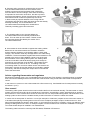
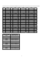
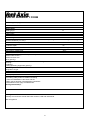
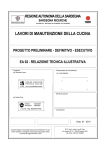
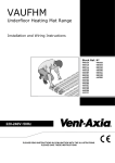
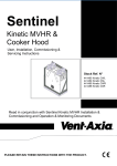
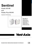
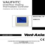
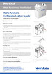
VAUFHC
Underfloor Heating Cable Range
Installation and Wiring Instructions
Stock Ref. N°
446201
446202
446203
446204
446205
446206
446207
446208
446209
446210
446211
446212
446213
220-240V~50Hz
PLEASE READ INSTRUCTIONS IN CONJUNCTION WITH THE ILLUSTRATIONS.
PLEASE SAVE THESE INSTRUCTIONS
Installation Instructions for BLUE THERMAL heating cables
Product description
BLUE THERMAL resistive twin conductor heating cable, with a metallic alloy as the warm conductor and a solid
copper wire as the return conductor. The heating cable has a factory fitted end seal and an integrated hidden splice
(marked SPLICE on the cable) between the cold lead and the heating element itself.
Constant power:
Rated Voltage:
Maximum Voltage:
Conductor insulation:
Outer sheath:
Minimum bending radius:
As stated on cable/package (Watt)
230V
500V
XLPE (PEX)
PVC
5x outer diameter of cable
Application
The main area of use for BLUE THERMAL cables is underfloor heating. Cable output [W] and output per meter [W/m]
are determined with regards to room size and type, type of installation and floor type. BLUE THERMAL cables can be
used both in new and renovation projects.
Important!
Before the installation starts Read through these installation instructions before any work starts. This product should
only be installed by qualified personnel, who are familiar with the construction and operation of the product and risks
involved. The installation of this heating product shall be in accordance with the manufacturer’s instructions and the
regulations of the authority having jurisdiction.
Measure insulation resistance and heating element resistance before the cable is taken out of the package.
The heating cable should never be installed directly in contact with combustible materials, except where the
following condtions are met:
•
The heating cable has an output per meter of 10W/m (3W/ft) or less
•
Heated area is 80W/m² (7,5W/ft²) or less
To prevent high temperatures in the floor construction the following must be followed:
•
Max. 80 W/m²(7,5W/ft²), max 10W/m (3W/ft) in wooden floors*
•
Max. 80 W/m²(7,5W/ft²) when the top surface is parquet*, laminate*, or carpet.
•
Max. 150W/m² (13,9W/ft²) when the top covering is stone, tiles, vinyl or linoleum.
* When installing heating cables beneath a wooden floor it is recommended to contact the vendor of the floor, to
ensure the floor is suitable for the planned heating system including output in W/m² (W/ft²). Some wooden floors, allow
a maximum area power as low as 60W/m² (5,6W/ft²) and restriction on maximum surface temperature as low as
27˚C(81˚F).
Installation instructions – step by step
1. Plan the installation first and then lay the cable
in the pre-calculated C-C distance on the sub-floor.
It is recommended that the sub-floor is insulated to reduce
heat-loss downwards. However the heating cable must not
be in contact with the insulation or pressed down into it.
This can be prevented, e.g. by installing the cable on chicken wire.
It is often a good choice to start with placing the splice(s) in the
floor near the thermostat. The splice(s) must not be placed in a
tube or in a wall. The end-seal of a twin conductor cable is
preferably placed in a dry zone of the floor.
Apply glue, attach bands, or fix cable ties to keep the heating cable in
place at the correct C-C distance. It is important that the cable will stay
in place when the floor is poured. Keep the correct distance (C-C)
between cables, and avoid at all times overlapping or crossing of
cables, as this causes unwanted thermal effects.If attaching the heating cable to reinforcement bars, longitudinal bars
are preferred. The heating cable shall not be attached to pipes in the floor or other components preventing heat flow.
Be aware that the cable will be exposed during installation to mechanical damage when placed on reinforcement bars.
Heating cables should not be installed beneath kitchen cupboards, walls or other permanent installations which do not
allow air circulation. Furniture that stands on the heated area must have feet to ensure that air can circulate and that
heat emission from the floor is possible. The heating cable is never to be cut or shortened in any way. If a floor sensor
is connected to the thermostat this should be installed inside a tube exactly between two cable strings in the floor. The
end of the tube should be sealed with tape. When installing the sensor in a tube, it can be changed later if needed.
Make a drawing of the installation and/or take a photograph for future reference before pouring the floor.
2
2. Avoid stepping or dropping items on the cable
and use caution in further works with pouring the floor.
3. Measure insulation resistance and element
resistance after the cable has been installed
but before any concrete/screed/mortar is poured.
To build a good and efficient heated floor the slab on the subfloor containing the heating cables must have good heat
conductivity to create an even temperature throughout the
slab, securing efficient heat emission from the cable to the
room.
4. When embedding heating cables in concrete/screed/mortar
this must be mixed correctly as prescribed by the vendor.
Mix the materials well, before pouring the concrete/screed/mortar
onto the subfloor and the cables.
5. BLUE THERMAL cables must be embedded
with minimum 5 mm (0,2 inches) concrete/screed/mortar
above the cable when the top floor covering is tile or stone.
The minimum is 10 mm when the top floor covering is vinyl,
linoleum, carpet, engineered wood or other.
3
6. Compact well to prevent air pockets and a porous slab.
The concrete/screed/mortar must surround the cable
entirely to ensure good and necessary heat conductivity
from the cable to it’s surroundings. Good heat conductivity
is important for the function of the floor, but also to prevent
excessive temperatures. Some concrete types can be mixed
with small amounts of water as specified by the vendor.
In these cases pay special attention to the mixing and the
compacting as these floors easily becomes porous and thereby
thermally insulating. It is recommended to use
concrete/screed/mortar designed for heated floors.
Thermally insulating types cannot be used.
7. The heating cable is not to be used before the
concrete/screed/mortar has naturally hardened and
dried. This can take up to 6-8 weeks. Please consult
the instructions/guide provided by the vendor of the
concrete/screed/mortar.
8. A thermostat is recommended to regulate the heating cables.
Before this is connected measure the insulation resistance
and the element resistance of the heating cable to check cable
integrity. This will also reveal any damage done to the cable during
installation. The documentation supplied with the thermostat is to be
passed to the owner of the installation, being a part of the total
documentation of the heating cable system. The heating cable
must be connected to electrical earth properly and always be
protected by a ground fault circuit breaker. This breaker should
have a maximum trip value of 30 mA. If installing more than
one heating cable in a room both cables can be connected to the
thermostat. However ensure the cables are connected in parallel
(not series), and that the total power output does not exceed the
limit of the thermostat.
Advice regarding thermostats and regulators
Electrical floor heating gives a very comfortable and economical heat. Floor heating is somewhat slower to regulate
than wall mounted heating and the best results are achieved when using an electronic thermostat for temperature
control.
In wet rooms it is common to use a thermostat with a floor sensor only. Comfortable bare foot temperature is usually
around 26˚C (79˚F).
User manual
The heating cable system should not be turned on before the floor has hardened naturally. The thermostat or control
system must be used according to the manufacturer’s instructions. Avoid drilling, cutting, attaching bolts or similar in
the heated floor. If this must be done contact an electrician who can help locate heating cables. Documentation of the
heating system received from the installer should provide information on where the cables are located.
In rooms with an area power of 100 W/m² or more (for example in a bathroom) carpets are not to be used. Caution is
to be taken when placing insulating items on the floor such as diaper packages, heaps of clothes and so on. Such
items should preferably be placed in other areas. In rooms with an area power of 100W/m² or less, pay attention when
placing insulating items on the floor, for example carpets or furniture without feet. Permanent installations covering a
room area should always be installed in non-heated areas.
The heating cable is tested in conformity with IEC 60800, EN50265 / IEC 60332-1.
4
The table below shows recommended BLUE THERMAL heating cables 17W/m and centre spacing for various room sizes and outputs
Room
m²
3
4
5
6
7
8
9
10
11
12
13
14
15
16
17
18
19
20
21
22
23
24
25
26
27
28
29
30
Load
60-80 W/m²
cc-cm
1 x 446201
1 x 446201
1 x 446202
1 x 446203
1 x 446203
1 x 446204
1 x 446204
1 x 446205
1 x 446205
1 x 446206
1 x 446206
1 x 446207
1 x 446207
1 x 446208
1 x 446208
1 x 446208
1 x 446208
1 x 446209
1 x 446209
1 x 446209
1 x 446210
1 x 446210
1 x 446210
1 x 446210
1 x 446211
1 x 446211
1 x 446211
22
28
25
23
27
25
28
26
29
26
28
25
27
23
24
25
27
26
27
28
24
25
26
27
23
23
24
Load
80-100 W/m²
1 x 446201
1 x 446202
1 x 446202
1 x 446203
1 x 446204
1 x 446205
1 x 446206
1 x 446206
1 x 446206
1 x 446207
1 x 446207
1 x 446208
1 x 446208
1 x 446209
1 x 446209
1 x 446209
1 x 446210
1 x 446210
1 x 446210
1 x 446210
1 x 446211
1 x 446211
1 x 446211
1 x 446212
1 x 446212
1 x 446212
1 x 446212
1 x 446212
cc-cm
17
17
21
20
20
19
18
20
22
20
22
19
20
19
21
22
19
20
21
22
18
19
20
17
18
18
19
20
Stock Ref number
Model/Cable rating
446201
VAUFHC 300W/17.6m
446202
VAUFHC 400W/23.5m
446203
VAUFHC 500W/29.3m
446204
VAUFHC 600W/35.2m
446205
VAUFHC 700W/41.0m
446206
VAUFHC 840W/49.7m
446207
VAUFHC 1000W/58.3m
446208
VAUFHC 1250W/72.4m
446209
VAUFHC 1370W/80.8m
446210
VAUFHC 1700W/100.0m
446211
VAUFHC 2100W/123.7m
446212
VAUFHC 2600W/154.5m
446213
VAUFHC 3300W/194.0m
Load
100-120 W/m²
1 x 446201
1 x 446202
1 x 446203
1 x 446205
1 x 446206
1 x 446206
1 x 446207
1 x 446207
1 x 446208
1 x 446209
1 x 446209
1 x 446209
1 x 446210
1 x 446210
1 x 446210
1 x 446211
1 x 446211
1 x 446211
1 x 446211
1 x 446212
1 x 446212
1 x 446212
1 x 446212
2 x 446209
2 x 446209
1 x 446213
1 x 446213
1 x 446213
5
cc-cm
17
17
17
14
14
16
15
17
15
15
16
17
15
16
17
14
15
16
17
14
15
16
16
16
17
14
15
15
Load
120-150 W/m²
1 x 446202
1 x 446203
1 x 446204
1 x 446206
1 x 446207
1 x 446207
1 x 446208
1 x 446208
1 x 446209
1 x 446210
1 x 446210
1 x 446210
1 x 446211
1 x 446211
1 x 446211
1 x 446212
1 x 446212
1 x 446212
1 x 446212
2 x 446209
1 x 446213
1 x 446213
1 x 446213
1 x 446213
1 x 446213
2 x 446210
2 x 446211
1 x 446211
cc-cm
12
13
14
12
12
13
12
13
13
12
13
14
12
13
13
12
12
13
14
14
12
12
13
13
14
14
11
12
VAUFHC WARRANTY FORM
Installed by (Company):
Installation address:
Room/area:
Rated values
Cable type(s):
Single-/Twin conductor:
Linear output:
Rated resistance:
Rated voltage:
Check measurements
Before installation
Before pouring
Element resistance (-5/+10%):
Insulation resistance (>100 MOhm):
Construction details
Installation depth:
No. of elements/mats installed:
Installed/heated area:
Area output in heated area:
Size circuit breaker:
Trip level RCD/GFCI (ground fault protection):
Earthed cable screen:
Earthed chicken wire:
Other (specify):
Max. temperature in construction is limited to 80 ˚C by:
Planning:
Installation:
Limiting/protecting equipment (specify):
Control system
Designation of type:
Floor sensor
Room sensor
Other specify
Installer statement
The heating cable product is installed according
to Vent-Axia installation instructions and the
building owner has been informed about precautions
and limitations which apply to heated floors.
Date/signature/stamp:
Special notes about this installation
Building owner / Purchaser
Warranty form and user manual has been received, read and understood.
Date & Signature
6
m²
W
Before connecting
Date & signature
cm
stk/st/kpl/pieces
m²
W/m²
A
≤30mA
7
Product extended warranty
All of our heating cable units and their components are thoroughly tested during production. The final test is a high
voltage test and measurement of the conductor resistance. Only the units which have passed the tests, are sent to the
market. Vent-Axia offers an extended 10-year warranty on defects in material and workmanship in the sold product,
under proper and normal use and service. In case of a defect, Vent-Axia will repair or replace the product. Please see
the terms of warranty for further details. The warranty does not extend to defects caused by a faulty installation. For
the extended warranty to be valid these installation instructions must be accompanied with. The written warranty form
inside each box containing a product must be filled in. This is to ensure a correct installation and that no damage has
been done to the product during the installation. If, during the installation, a heating cable is damaged, it will have to be
replaced before the construction is finished. Vent-Axia must be given notice of any defect within 30 days after the
defect was discovered, and the warranty form correctly filled in must accompany the claim in order for the extended
warranty to be valid.
The abc Guarantee
Applicable only to products installed and used in the United Kingdom. For details of guarantee outside the United Kingdom contact your local
supplier.
Vent-Axia guarantees its products for two years from date of purchase against faulty material or workmanship. In the event of any part being found
to be defective, the product will be repaired, or at the Company’s option replaced, without charge, provided that the product:•
•
•
•
Has been installed and used in accordance with the instructions given with each unit.
Has not been connected to an unsuitable electricity supply. (The correct electricity supply voltage is shown on the product rating label
attached to the unit).
Has not been subjected to misuse, neglect or damage.
Has not been modified or repaired by any person not authorised by the company.
IF CLAIMING UNDER TERMS OF GUARANTEE
Please return the complete product, carriage paid to your original supplier or nearest Vent-Axia Centre, by post or personal visit. Please ensure
that it is adequately packed and accompanied by a letter clearly marked “Guarantee Claim” stating the nature of the fault and providing evidence of
date and source of purchase.
The guarantee is offered to you as an extra benefit, and does not effect your legal rights
Head Office: Fleming Way, Crawley, West Sussex, RH10 9YX. Tel: 01293 526062 Fax: 01293 551188
UK NATIONAL CALL CENTRE, Newton Road, Crawley, West Sussex, RH10 9JA
SALES ENQUIRIES:
Tel: 0844 8560590
Fax: 01293 565169
TECHNICAL SUPPORT:
Tel: 0844 8560594
Fax: 01293 539209
For details of the warranty and returns procedure please refer to www.vent-axia.com or write to Vent-Axia Ltd, Fleming Way, Crawley, RH10 9YX
446258A
0111
8