1
OneCommand Manager™ for VMware vCenter Version 1.4 User Manual P008706-01A Rev. A Emulex Connects™ Servers, Storage and People 2 Copyright © 2011-2012 Emulex. All rights reserved worldwide. No part of this document may be reproduced by any means or translated to any electronic medium without the prior written consent of Emulex. Information furnished by Emulex is believed to be accurate and reliable. However, no responsibility is assumed by Emulex for its use; or for any infringements of patents or other rights of third parties which may result from its use. No license is granted by implication or otherwise under any patent, copyright or related rights of Emulex. Emulex, the Emulex logo, AutoPilot Installer, AutoPilot Manager, BlockGuard, Connectivity Continuum, Convergenomics, Emulex Connect, Emulex Secure, EZPilot, FibreSpy, HBAnyware, InSpeed, LightPulse, MultiPulse, OneCommand, OneConnect, One Network. One Company., SBOD, SLI, and VEngine are trademarks of Emulex. All other brand or product names referenced herein are trademarks or registered trademarks of their respective companies or organizations. Emulex provides this manual "as is" without any warranty of any kind, either expressed or implied, including but not limited to the implied warranties of merchantability or fitness for a particular purpose. Emulex may make improvements and changes to the product described in this manual at any time and without any notice. Emulex assumes no responsibility for its use, nor for any infringements of patents or other rights of third parties that may result. Periodic changes are made to information contained herein; although these changes will be incorporated into new editions of this manual, Emulex disclaims any undertaking to give notice of such changes. Emulex, 3333 Susan Street Costa Mesa, CA 92626 OCM for VMware vCenter Version 1.4 User Manual P008706-01A Rev. A Table of Contents Table of Contents List of Figures .................................................................................... 11 List of Tables ..................................................................................... 14 1. Introduction ................................................................................... 15 Abbreviations ........................................................................................ 18 2. Installing and Uninstalling OCM for VMware vCenter Components................. 22 Best Installation Practices ......................................................................... 22 Prerequisites ......................................................................................... 22 Hardware Requirements ........................................................................22 Software Requirements .........................................................................22 Installing OCM for VMware vCenter.............................................................. 23 Verifying the OCM for VMware vCenter Installation ........................................26 Enabling and Disabling OCM for VMware vCenter............................................. 27 Registering and Unregistering OCM for VMware vCenter ................................... 28 Uninstalling OCM for VMware vCenter .......................................................... 29 Reinstalling OCM for VMware vCenter .......................................................... 29 3. Using OCM for VMware vCenter ........................................................... 31 Behavior of OCM for VMware vCenter Settings in the ESX Server ......................... 31 Active Directory..................................................................................31 Privileges for OCM for VMware vCenter .......................................................... 31 Lockdown Mode Feature ........................................................................31 Accessing the vSphere Console ................................................................32 vSphere Console Views............................................................................. 32 Using OCM for VMware vCenter Web Client.................................................... 34 Enabling OCM for VMware vCenter ............................................................34 Launching OCM for VMware vCenter Web Client............................................35 4. Cluster View................................................................................... 37 Viewing Host Information in a Cluster ........................................................37 Hosts Information Field Definitions ............................................................... 37 Viewing Adapter Information ..................................................................38 Adapters Information Field Definitions ........................................................... 38 Viewing Port Information in a Cluster (Host-centric mode)...............................39 Host-centric Information Field Definitions....................................................... 40 Viewing Virtual Port Information in a Cluster (Host-centric mode)......................41 OCM for VMware vCenter Version 1.4 User Manual P008706-01A Rev. A 3 Table of Contents Virtual Port Information Field Definitions ....................................................... 41 Viewing Port Information in a Cluster (Fabric-centric mode).............................42 Fabric-centric Information Field Definitions..................................................... 43 Performing a Batch Firmware Update in Cluster View ..................................... 44 Updating Firmware on Multiple Adapters ....................................................45 Batch Firmware Update Jobs Window Field Definitions ....................................... 47 Exporting SAN Information in the Cluster View .............................................48 Export SAN Info Window Field Definitions ....................................................... 49 5. Host View ...................................................................................... 52 Viewing Information for a Single Host .......................................................52 Host Information Field Definitions ................................................................ 52 Viewing Driver Parameters of All Adapters in a Host ......................................53 Host Driver Parameters Tab Field Definitions ................................................... 54 Setting Driver Parameters for All Adapters in a Host ......................................55 Viewing Firmware Information of All Adapters in a Host .................................55 Host Maintenance Tab Field Definitions.......................................................... 56 Updating Firmware on Adapters in a Host ...................................................56 Jobs Window Field Definitions ..................................................................... 59 6. Adapter View.................................................................................. 60 Viewing LightPulse (FC) Adapter Information ...............................................60 FC Adapter Information Field Definitions ........................................................ 60 Viewing OneConnect Adapter Information...................................................61 OneConnect Adapter Tab Field Definitions ...................................................... 62 7. Port View ...................................................................................... 64 FC and FCoE Ports................................................................................... 64 Viewing FC Port Details and Changing Link State ...........................................64 FC Port Details Tab Field Definitions ............................................................. 64 Viewing FC/FCoE Target Information.........................................................66 Target Information Field Definitions.............................................................. 66 Viewing FC Port Statistics .....................................................................66 Port Statistics Tab Field Definitions .............................................................. 67 Viewing FC/FCoE LUN Information ............................................................68 FC/FCoE LUN Information Field Definitions ..................................................... 69 Viewing PCI Registers for an FC Port .........................................................69 Viewing FC Port Transceiver Information ....................................................70 Transceiver Information Field Definitions ....................................................... 71 Viewing Flash Contents .........................................................................72 Viewing FC Port Firmware Versions ...........................................................72 OCM for VMware vCenter Version 1.4 User Manual P008706-01A Rev. A 4 Table of Contents Maintenance Tab Field Definitions ................................................................ 73 Updating Firmware for an FC Port ............................................................74 Jobs Window Field Definitions ..................................................................... 75 Changing WWN Configuration for an FC Port ................................................76 Resetting an FC Port ............................................................................79 Viewing FC Port Driver Parameters ...........................................................80 Driver Parameters Tab Field Definitions ......................................................... 80 Setting Driver Parameters for an FC Port ....................................................81 Saving Driver Parameters for an FC Port to a File ..........................................81 Viewing FC Port Vital Product Data (VPD) ...................................................82 VPD Table Definitions ............................................................................... 82 Viewing FCoE Port Details ......................................................................83 FCoE Port Details Field Definitions................................................................ 83 Enabling/Disabling PFC Throttle on an FCoE Port ..........................................84 Viewing FCoE Port Statistics ..................................................................85 Port Statistics Field Definitions.................................................................... 85 Viewing PCI Registers for an FCoE Port.......................................................87 Viewing Firmware Versions for an FCoE Port ................................................88 Maintenance Tab Field Definitions ................................................................ 88 Changing WWN Configuration for an FCoE Port .............................................89 Resetting an FCoE Port..........................................................................91 Viewing FCoE Port Driver Parameters ........................................................92 Driver Parameters Tab Field Definitions ......................................................... 92 Setting Driver Parameters for an FCoE Port .................................................93 Saving Driver Parameters for an FCoE Port to a File .......................................93 Viewing FCoE Port Vital Product Data (VPD) ................................................94 VPD Table Definitions ............................................................................... 94 Viewing FIP Parameters for an FCoE Port ....................................................95 FIP Tab Field Descriptions .......................................................................... 95 Configuring FIP Parameters for an FCoE Adapter ...........................................96 iSCSI Port ............................................................................................. 96 Viewing iSCSI Port Information ................................................................96 iSCSI Port Info Tab Field Definitions .............................................................. 97 Enabling iSCSI Boot .................................................................................. 98 Viewing PCI Registers for an iSCSI Port.......................................................98 Viewing iSCSI iSNS Server Information........................................................99 iSNS Tab Field Definitions ........................................................................ 100 Disabling the iSNS Server ..................................................................... 100 Changing the iSNS Server ..................................................................... 100 Viewing iSCSI Initiator Statistics............................................................. 100 OCM for VMware vCenter Version 1.4 User Manual P008706-01A Rev. A 5 Table of Contents iSCSI Statistics Tab Field Definitions............................................................ 101 Viewing iSCSI Initiator Login Options ....................................................... 102 iSCSI Initiator Login Options Tab Field Definitions............................................ 104 Initiator Default Login Options Window Field Definitions ................................... 105 Viewing iSCSI Target Discovery Information ............................................... 106 iSCSI Target Discovery Tab Field Definitions .................................................. 106 Viewing iSCSI Target Information ........................................................... 106 iSCSI Target Information Tab Field Definitions................................................ 107 Viewing Target Session Information ........................................................ 107 Target Sessions Window Field Definitions...................................................... 108 Configuring iSNS for iSCSI Target Discovery ............................................... 110 Viewing iSCSI LUN Information............................................................... 110 iSCSI LUN Info Tab Field Definitions ............................................................ 111 Viewing iSCSI Port Vital Product Data (VPD)............................................... 111 VPD Table Definitions ............................................................................. 112 NIC Port ..............................................................................................112 Viewing NIC Port Information ................................................................ 112 NIC Port Information Tab Field Definitions .................................................... 113 Viewing PCI Registers for a NIC Port ........................................................ 115 Viewing NIC Port Vital Product Data (VPD) ................................................ 116 VPD Table Definitions ............................................................................. 116 8. OneConnect Adapter Port Management ............................................... 117 Viewing and Installing Licenses for OneConnect Adapters ................................117 Viewing Available Licenses ................................................................... 117 Installing Licenses ............................................................................. 118 Changing Personalities on OneConnect Adapters............................................118 Viewing and Updating OneConnect Adapter Firmware Information .....................119 Viewing OneConnect Adapter Firmware Information .................................... 119 Maintenance Tab Field Definitions .............................................................. 120 Updating Firmware for OneConnect Adapters............................................. 120 Viewing and Configuring Physical Ports for OneConnect Adapters ......................122 Viewing Physical Ports for OneConnect Adapters......................................... 122 Physical Port Info Tab Field Definitions ........................................................ 122 Configuring a Physical Port for OneConnect Adapters ................................... 123 Enabling or Disabling a Physical Port ........................................................... 123 Changing a Physical Port’s Speed ............................................................... 123 Change Port Speed Field Definitions ............................................................ 124 Viewing Physical Data for OneConnect 10GBaseT Series Adapters..................... 124 PHY Data Tab Field Definitions .................................................................. 125 OCM for VMware vCenter Version 1.4 User Manual P008706-01A Rev. A 6 Table of Contents Viewing Port Transceiver for a OneConnect Adapter .................................... 126 Transceiver Information Field Definitions ..................................................... 126 Viewing and Configuring OneConnect Physical Port DCB Parameters ...................127 Viewing Physical Port DCB Parameters ..................................................... 127 DCB Tab Field Definitions......................................................................... 128 Configuring OneConnect Physical Port DCB Parameters ................................. 130 Configure DCB Dialog Box Field Definitions .................................................... 131 9. Diagnostics................................................................................... 134 Running Diagnostic Tests on FC Adapter Ports ...............................................134 Running Loopback Tests ...................................................................... 134 Running End-to-End (ECHO) Tests ........................................................... 135 Running a Power On Self Test (POST) ...................................................... 135 Using Beaconing................................................................................ 136 Setting Up Diagnostic Test Options ......................................................... 136 Setting Up a Test Failure Error Action.......................................................... 136 Setting Up Test Cycles ............................................................................ 136 Setting Up a Test Pattern......................................................................... 136 Test Status .......................................................................................... 136 Saving the Log File............................................................................. 137 Creating FC Port Diagnostic Dumps ......................................................... 137 Diagnostic Dump Tab Field Definitions ......................................................... 138 Viewing Diagnostic Dumps Files ............................................................. 139 Running Diagnostic Tests on OneConnect Adapter Ports...................................141 Running Loopback Tests ...................................................................... 141 Using Beaconing................................................................................ 142 Running a TDR Test (10GBaseT Series Adapters Only) ................................... 142 Setting Up Diagnostic Test Options ......................................................... 143 Setting Up a Test Failure Error Action.......................................................... 143 Setting Up Test Cycles ............................................................................ 143 Setting Up a Test Pattern......................................................................... 143 Test Status .......................................................................................... 143 Saving the Log File............................................................................. 143 Creating OneConnect Port Diagnostic Dumps ............................................. 144 Diagnostic Dump Tab Field Definitions ......................................................... 145 Viewing Diagnostic Dumps Files ............................................................. 146 10. Using OCM for VMware vCenter Command Line Interface ....................... 148 Using the CLI Client ................................................................................149 Syntax Rules .................................................................................... 149 The Command Reference.........................................................................149 OCM for VMware vCenter Version 1.4 User Manual P008706-01A Rev. A 7 Table of Contents help (single command)........................................................................ 149 Syntax................................................................................................ 149 Description.......................................................................................... 149 Parameters.......................................................................................... 149 help (group) .................................................................................... 149 changepersonality ............................................................................. 152 changewwn ..................................................................................... 153 clearisnsserver ................................................................................. 153 deletedumpfiles................................................................................ 153 driverconfig ..................................................................................... 154 dump............................................................................................. 154 echotest ......................................................................................... 155 enablebootcode ................................................................................ 156 exportsaninfo................................................................................... 156 firmwareupdate ................................................................................ 157 getbeacon ....................................................................................... 158 getdcbparams .................................................................................. 159 getdriverparams................................................................................ 159 getdriverparamsglobal ........................................................................ 159 getdumpdirectory.............................................................................. 160 getdumpfilenames ............................................................................. 160 getfcfinfo ....................................................................................... 161 getfipparams ................................................................................... 161 getinitiatorproperties ......................................................................... 162 getiscsiluns...................................................................................... 162 getiscsiportstats................................................................................ 163 getlunlist ........................................................................................ 163 getpcidata ...................................................................................... 163 getpginfo ........................................................................................ 164 getportstatistics................................................................................ 164 getretentioncount ............................................................................. 165 getsessioninfo .................................................................................. 165 getvpd ........................................................................................... 166 getwwncap...................................................................................... 166 getxcvrdata ..................................................................................... 167 hbaattributes ................................................................................... 167 installadapterlicense .......................................................................... 168 listhbas .......................................................................................... 168 listsessions ...................................................................................... 169 OCM for VMware vCenter Version 1.4 User Manual P008706-01A Rev. A 8 Table of Contents listvms ........................................................................................... 169 listvports ........................................................................................ 170 loadlist........................................................................................... 170 loopbacktest .................................................................................... 171 pcidata .......................................................................................... 172 portattributes .................................................................................. 172 posttest.......................................................................................... 173 readwwn ........................................................................................ 173 reset ............................................................................................. 174 restorewwn ..................................................................................... 175 saveconfig....................................................................................... 175 serverattributes ................................................................................ 176 setbeacon ....................................................................................... 176 setcablenvp ..................................................................................... 177 setcnapgbw ..................................................................................... 178 setdcbparam.................................................................................... 178 setdcbpriority .................................................................................. 180 setdriverparam ................................................................................. 182 setdriverparamdefaults ....................................................................... 182 setdumpdirectory .............................................................................. 183 setfipparams.................................................................................... 184 setpfcthrottle .................................................................................. 184 setphyportspeed ............................................................................... 185 setportenabled ................................................................................. 186 setretentioncount.............................................................................. 186 setvccred........................................................................................ 187 showisnsserver ................................................................................. 188 showlicenseadapterfeatures ................................................................. 188 showlicenseadapterid ......................................................................... 189 showpersonalities .............................................................................. 189 showtarget ...................................................................................... 190 targetmapping.................................................................................. 190 tdrtest ........................................................................................... 190 umcEnable ...................................................................................... 191 umcgetparams.................................................................................. 191 umcSetBW....................................................................................... 192 umcSetChanLink ............................................................................... 193 umcSetLPVID.................................................................................... 193 updateisnsserver ............................................................................... 194 OCM for VMware vCenter Version 1.4 User Manual P008706-01A Rev. A 9 Table of Contents version........................................................................................... 195 Viewing Audit Logs Using the CLI Command ..................................................195 11. Troubleshooting .......................................................................... 197 Issues and Resolutions.............................................................................197 OCM for VMware vCenter Version 1.4 User Manual P008706-01A Rev. A 10 List of Figures List of Figures Figure 2-1 Figure 2-2 Figure 2-3 Figure 2-4 Figure 2-5 Figure 2-6 Figure 2-7 Figure 2-8 Figure 2-9 Figure 3-1 Figure 3-2 Figure 3-3 Figure 4-1 Figure 4-2 Figure 4-3 Figure 4-4 Figure 4-5 Figure 4-6 Figure 4-7 Figure 4-8 Figure 4-9 Figure 4-10 Figure 4-11 Figure 4-12 Figure 4-13 Figure 4-14 Figure 4-15 Figure 5-1 Figure 5-2 Figure 5-3 Figure 5-4 Figure 5-5 Figure 5-6 Figure 6-1 Figure 6-2 Figure 7-1 Figure 7-2 Figure 7-3 Installation Options Window.............................................................23 OCM for VMware vCenter Configuration Window.....................................24 OCM for VMware vCenter Configuration Window with Port in Use Warning ................................................................24 Register/Unregister Dialog Box .........................................................25 vSphere Console ...........................................................................26 Plug-in Manager Window .................................................................26 Plug-in Manager with Selected Row ....................................................27 Register/Unregister Dialog Box .........................................................28 Reinstallation Configuration Dialog Box ...............................................30 Host-Centric Cluster View ...............................................................33 Host View...................................................................................34 vSphere Web Client Plug-In Management Page.......................................35 Hosts Information Pane ..................................................................37 Adapters Information .....................................................................38 Host-Centric Cluster View ...............................................................39 Close-Up of Host-Centric Cluster View ................................................40 Virtual Port Cluster View ................................................................41 Fabric-Centric Cluster View .............................................................42 Close-up of Fabric-Centric Cluster View...............................................43 Batch Firmware Update Information Pane ............................................44 Batch Firmware Download Dialog Box, Host-Centric View..........................45 Batch Firmware Download Dialog Box, Fabric-Centric View .......................46 Batch Firmware Update Jobs Window .................................................47 Export SAN Info ............................................................................48 Export SAN Info Dialog Box ..............................................................49 Export SAN Info Jobs Window, Active Jobs List ......................................50 Export SAN Info Jobs Window, Completed Jobs List .................................51 Host Information Pane....................................................................52 Host Driver Parameters Pane............................................................54 Host Maintenance Tab....................................................................56 Empty Batch Firmware Download Dialog Box .........................................57 Populated Batch Firmware Download Dialog Box ....................................57 Jobs Window ...............................................................................58 FC Adapter Information Tab.............................................................60 OneConnect Adapter Information Tab .................................................61 FC Port Details Tab .......................................................................64 Target Information Tab ..................................................................66 FC Port Statistics Tab.....................................................................67 OCM for VMware vCenter Version 1.4 User Manual P008706-01A Rev. A 11 List of Figures Figure 7-4 Figure 7-5 Figure 7-6 Figure 7-7 Figure 7-8 Figure 7-9 Figure 7-10 Figure 7-11 Figure 7-12 Figure 7-13 Figure 7-14 Figure 7-15 Figure 7-16 Figure 7-17 Figure 7-18 Figure 7-19 Figure 7-20 Figure 7-21 Figure 7-22 Figure 7-23 Figure 7-24 Figure 7-25 Figure 7-26 Figure 7-27 Figure 7-28 Figure 7-29 Figure 7-30 Figure 7-31 Figure 7-32 Figure 7-33 Figure 7-34 Figure 7-35 Figure 7-36 Figure 7-37 Figure 7-38 Figure 7-39 Figure 7-40 Figure 8-1 Figure 8-2 Figure 8-3 Figure 8-4 Figure 8-5 FC LUN Information Tab..................................................................69 FC Port PCI Registers Tab ................................................................70 FC Port Transceiver Tab .................................................................71 FC Port Flash Contents ...................................................................72 FC Port Maintenance Tab ................................................................73 Firmware Download dialog box .........................................................74 Jobs Window ...............................................................................75 Change WWN Configuration Dialog Box ................................................78 Warning About Changing WWN ..........................................................79 Reset Port Warning .......................................................................79 FC Port Driver Parameters Tab .........................................................80 FC Port VPD Tab ...........................................................................82 FCoE Port Details Tab ....................................................................83 FCoE Port Statistics Tab..................................................................85 FCoE Port PCI Registers Tab .............................................................87 FCoE Port Maintenance Tab .............................................................88 Change WWN Configuration dialog box ................................................90 Warning About Changing WWN ..........................................................91 Reset Port Warning .......................................................................91 FCoE Port Driver Parameters Tab.......................................................92 FCoE Port VPD Tab ........................................................................94 FCoE Port FIP Tab .........................................................................95 iSCSI Port Info Tab ........................................................................97 iSCSI Port, PCI Registers Tab ............................................................99 iSCSI Port, iSNS Tab.......................................................................99 iSCSI Port, Update iSNS Server Dialog Box .......................................... 100 iSCSI Initiator, iSCSI Statistics Tab ................................................... 101 iSCSI Initiator Logon Options Tab ..................................................... 103 iSCSI Initiator Default Login Options Window....................................... 103 iSCSI Target Discovery Tab ............................................................ 106 iSCSI Target Information Tab.......................................................... 107 iSCSI Target Sessions Window ......................................................... 108 iSCSI LUN Info Tab ...................................................................... 111 iSCSI Port VPD Tab ...................................................................... 112 NIC Port Information Tab .............................................................. 113 NIC Port PCI Registers Tab ............................................................. 115 NIC Port VPD Tab........................................................................ 116 License Features Area .................................................................. 117 Install Feature Licenses Dialog Box................................................... 118 OneConnect Adapter Maintenance Tab .............................................. 119 Firmware Download Dialog Box ....................................................... 120 Jobs Window ............................................................................. 121 OCM for VMware vCenter Version 1.4 User Manual P008706-01A Rev. A 12 List of Figures Figure 8-6 Figure 8-7 Figure 8-8 Figure 8-9 Figure 8-10 Figure 8-11 Figure 9-1 Figure 9-2 Figure 9-3 Figure 9-4 Figure 9-5 Figure 9-6 Figure 9-7 Figure 9-8 Figure 9-9 Figure 9-10 Figure 9-11 Figure 9-12 Figure 9-13 Figure 9-14 OneConnect OCe11XXX Series Adapter Physical Port Info Tab ................... 122 Change Port Speed Dialog Box ........................................................ 123 OneConnect Adapter PHY Data Tab .................................................. 125 OCe 10XXX Port Transceiver Tab ..................................................... 126 OneConnect FCoE Adapter Port, DCB Tab........................................... 128 DCB Configuration Dialog Box for FCoE Adapter Ports (DCBX Enabled)......... 130 FC Adapter Diagnostics Tab ........................................................... 134 Diagnostic Tests Warning .............................................................. 135 Diagnostic Test Log Entries ............................................................ 137 FC Port Diagnostic Dump Tab ......................................................... 138 Diagnostic Dump Files window ........................................................ 139 Datastores View of vSphere Client ................................................... 140 vSphere Datastore Browser ............................................................ 140 OneConnect Adapter Diagnostics Tab................................................ 141 Diagnostic Tests Warning .............................................................. 142 Diagnostic Test Log Entries ............................................................ 144 OneConnect Port Diagnostic Dump Tab.............................................. 145 Diagnostic Dump Files window ........................................................ 146 Datastores View of vSphere Client ................................................... 147 vSphere Datastore Browser ............................................................ 147 OCM for VMware vCenter Version 1.4 User Manual P008706-01A Rev. A 13 List of Tables List of Tables Table 1-1 Table 10-1 Table 11-1 Support Provided by Emulex CIM Provider Versions .................................16 Group and Supported Commands ..................................................... 150 Troubleshooting Issues and Resolutions ............................................. 197 OCM for VMware vCenter Version 1.4 User Manual P008706-01A Rev. A 14 1. Introduction 1. Introduction Emulex® OneCommand Manager™ for VMware vCenter (OCM for VMware vCenter) integrates the in-depth management of Emulex LightPulse® (LP) host bus adapters (HBAs) and OneConnect™ universal converged network adapters (UCNAs) into the VMware vCenter management console. This comprehensive solution builds upon standard Emulex CIM management providers and advanced functionality delivered with the Emulex OneCommand Manager application to present native configuration management, status monitoring, and online maintenance of Emulex adapters in VMware ESX and ESXi environments, using a graphical (GUI) or command line (CLI) user interface. OCM for VMware vCenter supports the following VMware platforms: VMware ESXi 5.1 VMware ESXi 5.0 VMware ESXi 4.1 VMware ESX 4.1 OCM for VMware vCenter can be hosted/registered on the following servers: vCenter Server 5.1 vCenter Server 5.0 vCenter Server 4.1 OCM for VMware vCenter version 1.4 is supported for the following operating systems: Windows Server 2008 SP2 (or later) – Standard, Enterprise and Datacenter editions (32 bit, x86) and (64 bit, x86_64) Windows Server 2008 R2 – Standard, Enterprise and Datacenter editions (32 bit, x86) and (64 bit, x86_64) Windows 7 (64-bit) Windows 2012 (64 bit) Refer to Table 1-1, Support Provided by Emulex CIM Provider Versions, on page 16 to determine the support provided by your Emulex Common Information Model (CIM) provider. Note: Screen shots in this manual are for illustrative purposes only. Your system information can vary. The features available in OCM for VMware vCenter are determined by the version of Emulex CIM provider installed for Emulex LightPulse HBAs and OneConnect UCNAs. The following table lists the Emulex OneCommand Manager application support provided by each Emulex CIM provider package and the individual FC and UCNA providers in each package. The Emulex CIM provider packages can be downloaded from the Emulex website. OCM for VMware vCenter Version 1.4 User Manual P008706-01A Rev. A 15 1. Introduction Note: In Table 1-1, “” indicates the feature is supported on the particular Emulex CIM provider version and OCM for VMWare vCenter. In the OCM for VMware vCenter v1.3 and v1.4 column, an “” indicates that this feature is supported in both v1.3 and 1.4 unless otherwise indicated. ”N/A” table cells indicate that the feature is not applicable. Table 1-1 Support Provided by Emulex CIM Provider Versions ELX CIM Provider Package v3.6 ELX CIM Provider Package v3.7 UCNA FC UCNA FC OCM for VMware vCenter v1.3 and v 1.4 Discover virtual ports connected to an FC or FCoE port View virtual port information in a cluster (host-centric mode) N/A N/A N/A N/A Discover hosts, adapters (FC, FCoE, NIC and iSCSI), targets, and LUNs for selected ESX hosts Discover hosts and adapters (FC and FCoE) for selected ESX fabrics Display firmware revision Display boot code version Update firmware and FC boot code on a single adapter Update firmware and FC boot code on a per-fabric basis N/A N/A N/A N/A Change WWPN or WWN for FC adapters Locate adapters with beaconing N/A Display PCI-Express registers Physical Loopback test N/A N/A Emulex OneCommand Manager Application Features UCNA only MAC loopback test N/A N/A UCNA only PCI loopback test N/A N/A FC only Internal and External loopback test OCM for VMware vCenter Version 1.4 User Manual N/A N/A FC only P008706-01A Rev. A 16 1. Introduction Table 1-1 Support Provided by Emulex CIM Provider Versions (Continued) Emulex OneCommand Manager Application Features Echo test ELX CIM Provider Package v3.6 ELX CIM Provider Package v3.7 UCNA FC UCNA FC N/A OCM for VMware vCenter v1.3 and v 1.4 FC Only POST test N/A N/A FC only TDR tests N/A N/A UCNA – 10G Base-T only Batch update firmware and FC boot code to multiple adapters N/A N/A N/A N/A Enable/disable ports N/A N/A Get driver parameters (Global and Port) Set global driver parameters to adapters Set port driver parameters to adapters Target and LUN information Reset Port (FC and FCoE only) Toggle PFC throttle (FCoE only) N/A N/A UCNA OCe10XXX series only View VPD View transceiver data View physical data for 10GBase-T adapters N/A N/A iSCSI management N/A N/A Enable/disable FIP data N/A N/A UCNA 10GBase-T only UCNA only DCB configuration N/A N/A UCNA only OCM for VMware vCenter Version 1.4 User Manual P008706-01A Rev. A 17 1. Introduction Abbreviations Table 1-1 Support Provided by Emulex CIM Provider Versions (Continued) Emulex OneCommand Manager Application Features ELX CIM Provider Package v3.6 ELX CIM Provider Package v3.7 OCM for VMware vCenter v1.3 and v 1.4 UCNA FC UCNA FC Display flash contents (wakeup parameters/flash load list) Export SAN configuration information at cluster level and at host level N/A N/A N/A N/A Perform diagnostic dump at the adapter and port level Personality (protocol) change and licensing N/A N/A iBFT support FC only UCNA only N/A N/A N/A OCM for VMware vCenter v 1.4 for UCNAs only Bandwidth softcapability N/A N/A N/A OCM for VMware vCenter v 1.4 for UCNAs only UMC CLI N/A N/A N/A OCM for VMware vCenter v 1.4 for UCNAs only Abbreviations ASIC application-specific integrated circuit BIOS basic input-output system BOFM IBM BladeCenter Open Fabric Manager CDB command descriptor block CHAP Challenge Handshake Authentication Protocol CIM Common Interface Model CIN Cisco, Intel, Nuova (data center bridging exchange) CLI command line interface CLP command line protocol CNA Converged Network Adapter COS console operating system OCM for VMware vCenter Version 1.4 User Manual P008706-01A Rev. A 18 1. Introduction Abbreviations CRC cyclic redundancy check CSV comma-separated values DAC direct-attach copper DCB data center bridging DCBX data center bridging exchange DHCP Dynamic Host Configuration Protocol DMA direct memory access EC engineering change level ETO extended time out FC Fibre Channel FCoE Fibre Channel over Ethernet FIP FCoE Initialization Protocol FPMA fabric-provided MAC address FW firmware GUI graphical user interface HW hardware HBA host bus adapter iBFT iSCSI boot firmware table IEEE Institution of Electrical and Electronics Engineers I/O input/output IP internet protocol IPL initial program load IPv4 Internet Protocol version 4 IPv6 Internet Protocol version 6 iSCSI internet Small Computer System Interface ISID initiator session identifier iSNS internet Storage Name Server KB kilobyte LDPC low-density parity check LDTO link down time out LED light emitting diode LIP Loop Initialization Primitive LLDP Link Layer Discovery Protocol LUN logical unit number MAC media access control MDI medium dependent interface MN manufacturer ID OCM for VMware vCenter Version 1.4 User Manual P008706-01A Rev. A 19 1. Introduction Abbreviations MSE mean squared error MTU maximum transmission unit NCSI Network Controller Sideband Interface NIC network interface card (or controller) NOS not operational sequence NVP nominal velocity of propagation NVRAM non-volatile random-access memory OCM OneCommand™ Manager OS operating system OUI organizationally unique identifier PDU protocol data unit PFC priority-based flow control PGID priority group ID PHY physical layer PLL phase lock loop POST power-on self-test PXE Pre-boot Execution Environment QoS quality of service R2T request to transmit Recv received RHEL Red Hat Enterprise Linux RPI remote port indicator Rx receive SAN storage area network SCSI Small Computer System Interface SFCB Small Footprint CIM Broker SFP small form factor pluggable SLES SUSE Linux Enterprise Server SLI scalable link interface SNMP Simple Network Management Protocol SNR signal to noise ratio TCP Transmission Control Protocol TDR time-domain reflectometer Tx transmit UCNA Universal Converged Network Adapter ULP Upper Layer Protocol UMC Universal Multichannel OCM for VMware vCenter Version 1.4 User Manual P008706-01A Rev. A 20 1. Introduction Abbreviations UTF-8 U(Universal Character Set) Transformation Format –8 bit VPD vital product data VLAN virtual local area network VLANID virtual local area network id vNIC virtual NIC VPort virtual port WWN world wide name WWNN world wide node name WWPN world wide port name VM virtual machine Xmt transmitted XRI exchange resource indicator XML extensible markup language OCM for VMware vCenter Version 1.4 User Manual P008706-01A Rev. A 21 2. Installing and Uninstalling OCM for VMware vCenter Components Best Installation Practices 2. Installing and Uninstalling OCM for VMware vCenter Components Best Installation Practices OCM for VMware vCenter provides real-time management as a plug-in through the VMware vSphere console and VMware Web Client. The web client allows you to run OCM for VMware vCenter from the vSphere Web client. System performance is directly influenced by the speed and efficiency of the underlying network infrastructure. The following bullets outline recommendations to achieve the best application response times. To avoid network latencies, ensure that all the managed ESX hosts, the vCenter Server and the VI infrastructure client are in the same network. To avoid configuration conflicts, install the vCenter Server and the VI infrastructure client on different hosts within the same network. Prerequisites Hardware Requirements Physical or virtual (x86/x86_64) servers with a minimum RAM of 2 Gb/s and 250 Mb/s of disk space Software Requirements VMware ESX 4.1 and ESXi 4.1, 5.0, and 5.1 environments Operating system – Windows Server 2008 (32 and 64 bit), Windows 7 (64 bit) or Windows 2012 (64 bit) Adobe Flash Player 11.2 or later vCenter Server 4.1, 5.0 or 5.1 VI Infrastructure Client 4.1, or vSphere Client 5.0 or 5.1. vSphere Web Client to manage vcenter server using web client instead of vSphere client OneCommand Manager Core Application Kit (for VMware ESX COS environments only) Note: The OneCommand Manager Core Application Kit must be downloaded and installed on the ESX server that is to be managed by OCM for VMware. The OneCommand Manager Core Application Kit also includes the associated CIM providers. OCM for VMware vCenter Version 1.4 User Manual P008706-01A Rev. A 22 2. Installing and Uninstalling OCM for VMware vCenter Components Installing OCM for VMware vCenter Note: On the system where OCM for VMware vCenter is installed, make sure the port numbers configured during the installation are open and dedicated to the OCM for VMware vCenter server only. No other service should be listening on this port. Emulex CIM providers FC provider 2.2.42.1 or later UCNA provider 1.3a or later Driver and Firmware Requirements See the Emulex website for the latest compatible driver and firmware versions. Installing OCM for VMware vCenter Note: As part of the OCM for VMware vCenter installation, the OCM for VMware vCenter Web Client components are installed and registered. To install OCM for VMware vCenter in Windows: 1. From the Emulex website, download the ELXOCM-VMware-vCenter-<version>-Setup.exe installation file to your system. 2. Navigate to the system directory to which you downloaded the file. 3. Double-click ELXOCM-VMware-vCenter-<version>-Setup.exe. The OCM for VMware vCenter window appears. 4. Click Next. The License agreement window appears 5. Read the agreement and select the I agree to these terms and conditions checkbox and click Next. The Installation Options window with the default Installation folder appears. Figure 2-1 Installation Options Window 6. Ensure that the OCM for VMware vCenter checkbox is selected. OCM for VMware vCenter Version 1.4 User Manual P008706-01A Rev. A 23 2. Installing and Uninstalling OCM for VMware vCenter Components Installing OCM for VMware vCenter 7. Program files install by default to c:\Program Files\Emulex. To change this location, click Browse and navigate to where you want the program files to reside. 8. Click Install. The Operation in progress screen appears. When the process is complete, the OCM for VMware vCenter configuration window appears. Figure 2-2 OCM for VMware vCenter Configuration Window Default port numbers for OCM for VMware vCenter server are displayed. Note: The Windows firewall setting must allow incoming connections on the HTTP and HTTPS ports that you configure here. If the port numbers are already in use, a warning appears next to the port number. Figure 2-3 OCM for VMware vCenter Configuration Window with Port in Use Warning 9. Click Next. The Operation in progress screen appears. When the installation process is complete a message prompts you to launch the registration utility OCM for VMware vCenter Version 1.4 User Manual P008706-01A Rev. A 24 2. Installing and Uninstalling OCM for VMware vCenter Components Installing OCM for VMware vCenter 10. Click Yes. The Register/Unregister dialog box appears in a new browser window. Figure 2-4 Register/Unregister Dialog Box 11. Enter the following details of the vCenter Server: vCenter Server Name – The IP address of the vCenter Server. vCenter Server HTTPS Port – The HTTPS port number of the vCenter Server. Note: The vCenter Server HTTPS port is by default 443. You can change this value if you have configured a different HTTPS port while installing the vCenter. Username – The user with administrative privileges. Password – The user password. OCM Plug-in Server Name – The host name or IP address of the current host with which the plug-in must be registered. Select the IP address or host name of the current machine as discovered by the OCM for VMware vCenter server and vCenter client: The host name (default) The local IP address Other IP addresses 12. Click Register to register OCM for VMware vCenter with a new vCenter Server. Note: You can unregister an existing OCM for VMware vCenter by clicking Unregister. Note: If you change the IP address or the subnet mask of the machine hosting the plug-in server, you must unregister and register OCM for VMware Center. 13. When the operation is successful, a message is displayed. Click OK. 14. Close the browser window. The Installation completed window appears.Click Finish. An OCM for VMware vCenter Registration icon is created on the desktop. You do not need to reboot the system. OCM for VMware vCenter Version 1.4 User Manual P008706-01A Rev. A 25 2. Installing and Uninstalling OCM for VMware vCenter Components Installing OCM for VMware vCenter Verifying the OCM for VMware vCenter Installation To verify OCM for VMware vCenter installation: 1. Log in to the vCenter Server through the VMware vSphere console. 2. Enter the IP address and credentials of the vCenter Server where OCM for VMware vCenter is registered. The vSphere console appears. Figure 2-5 vSphere Console 3. In the vSphere console select Plug-ins from the menu bar and select Manage Plug-ins. The Plug-in Manager window appears. Figure 2-6 Plug-in Manager Window OCM for VMware vCenter Version 1.4 User Manual P008706-01A Rev. A 26 2. Installing and Uninstalling OCM for VMware vCenter Components Enabling and Disabling OCM for VMware vCenter 4. In the Plug-in Manager window, check the status of OCM for VMware vCenter (Emulex OneCommand). If the OCM for VMware vCenter installation is complete, the status of OCM for VMware vCenter (Emulex OneCommand) is enabled by default. Enabling and Disabling OCM for VMware vCenter If you disable OCM for VMware vCenter, the Emulex OneCommand tab immediately disappears from the vSphere console. If you enable OCM for VMware vCenter, the Emulex OneCommand tab immediately appears on the vSphere console. To change the status of OCM for VMware vCenter (Emulex OneCommand in Figure 2-7): 1. Log in to the vCenter Server through the VMware vSphere console. 2. Enter the IP address and credentials of the vCenter Server where OCM for VMware vCenter is registered. The vSphere console appears. 3. In the vSphere console select Plug-ins from the menu bar and select Manage Plug-ins. The Plug-in Manager window appears. 4. Click the Emulex OneCommand row. A context menu appears. Figure 2-7 Plug-in Manager with Selected Row 5. Select Enable or Disable. OCM for VMware vCenter Version 1.4 User Manual P008706-01A Rev. A 27 2. Installing and Uninstalling OCM for VMware vCenter Components Registering and Unregistering OCM for VMware vCenter Registering and Unregistering OCM for VMware vCenter Note: If you are using the vSphere Web Client, you must verify that the vSphere Web Client and the vCenter server are registered to the same vCenter Single Sign On server to ensure that the vSphere Web Client can access the vCenter server inventory. To register or unregister OCM for VMware vCenter with a new vCenter Server: 1. Double-click the OCM for VMware vCenter Registration icon on the desktop. This icon is created when OCM for VMware vCenter is successfully installed. The register/unregister dialog box is displayed. Figure 2-8 Register/Unregister Dialog Box 2. Enter the following details of the vCenter Server: vCenter Server Name – The IP address of the vCenter Server. vCenter Server HTTPS Port – The HTTPS port number of the vCenter Server. The vCenter Server HTTPS port is by default 443. You can change this value if you have configured a different HTTPS port while installing the vCenter. Username – The user with administrative privileges. Password – The user password. OCM Plug-in Server Name – The host name or IP address of the current host with which the plug-in must be registered. Select the IP address of the current machine as discovered by the OCM for VMware vCenter server and vCenter client: The local IP address (default) The host name Other IP addresses 3. Do one of the following: Click Register to register OCM for VMware vCenter with a new vCenter Server. -or Click Unregister to unregister an existing OCM for VMware vCenter with a vCenter Server. OCM for VMware vCenter Version 1.4 User Manual P008706-01A Rev. A 28 2. Installing and Uninstalling OCM for VMware vCenter Components Uninstalling OCM for VMware vCenter Note: If you change the IP address or the subnet mask of the machine hosting the plug-in server, you must unregister and re-register OCM for VMware Center. 4. When the operation is successful, a message is displayed. Click OK. 5. Close the browser window. Note: OCM for VMware vCenter can be registered with more than one vCenter Server. Uninstalling OCM for VMware vCenter Caution: When you uninstall OCM for VMware vCenter, ensure that you do not delete the default configuration and log files that are stored in the %TEMP%\Emulex\OCM for VMware directory. If these files are deleted, all historical information of active management performed from the host is permanently lost. Before you uninstall OCM for VMware vCenter, you must unregister it from the vCenter Server. For more information, refer to “Using OCM for VMware vCenter” on page 31. To uninstall OCM for VMware vCenter in a Windows system: 1. Double-click ELXOCM-VMware-vCenter-<version>-Setup.exe. The OCM for VMware vCenter window prompts you to reinstall/uninstall the application. Select Uninstall the application completely and click Next. A progress window is displayed. The screen indicating the detection of OCM for VMware vCenter appears. 2. Click OK. When uninstallation is complete, the Uninstallation Completed window is displayed. 3. Click Finish. You do not need to reboot the system. Reinstalling OCM for VMware vCenter To reinstall OCM for VMware vCenter in a Windows system: 1. Double-click ELXOCM-VMware-vCenter-<version>-Setup.exe. The OCM for VMware vCenter window prompts you to reinstall/uninstall the application. 2. Select Re-install the application and click Next. A progress window is displayed. The OCM for VMware vCenter window appears. 3. Click Next. The License agreement screen appears. 4. Read the agreement and select the I agree to these terms and conditions checkbox and click Next. The Installation Options window with the previous installation folder appears (Figure 2-1). OCM for VMware vCenter Version 1.4 User Manual P008706-01A Rev. A 29 2. Installing and Uninstalling OCM for VMware vCenter Components Reinstalling OCM for VMware vCenter 5. Click Install. OCM for VMware vCenter is uninstalled. The operation in progress window appears. When the process is complete, the OCM for VMware vCenter configuration window appears. Figure 2-9 Reinstallation Configuration Dialog Box If OCM for VMware vCenter was installed earlier with port numbers other than the defaults provided, those configured ports are shown. If the port numbers are already in use, a warning appears next to the port number. Note: The Windows firewall setting must allow incoming connections on the HTTP and HTTPS ports that you configure here. 6. Follow the on-screen instructions and complete the installation with steps 9 to 14 of “Installing OCM for VMware vCenter” on page 23. OCM for VMware vCenter Version 1.4 User Manual P008706-01A Rev. A 30 3. Using OCM for VMware vCenter Behavior of OCM for VMware vCenter Settings in the ESX Server 3. Using OCM for VMware vCenter Behavior of OCM for VMware vCenter Settings in the ESX Server Active Directory Refer to the vSphere manual on the VMware website for information on creating a user with required privileges and changing access permissions for a user in the Active Directory. Privileges for OCM for VMware vCenter Only a user with these specific privileges can read and perform active management in OCM for VMware vCenter: “Host.CIM.CIM Interaction” to read data through the OCM for VMware vCenter “Host.CIM.CIM Interaction” and “Host.Configuration.Maintenance” to perform any active management of the Emulex adapters “Extension.Register extension” to register OCM for VMware vCenter using the registration utility “Extension.Unregister extension” to unregister OCM for VMware vCenter using the registration utility All other users including the root user of the ESX host cannot perform any actions including reading data. If a user without the required privileges attempts to perform any action in OCM for VMware vCenter, an error message is displayed. Note: To configure user roles and assign privileges, refer to the VMware vCenter Server Manual. Lockdown Mode Feature Refer to the vSphere manual on the VMware website for information on enabling and disabling lockdown mode. If lockdown mode is enabled for an ESX host, then only a user with administrator privileges can access the ESX host and manage adapters using OCM for VMware vCenter. All other users including the root user will not have access to the ESX host. OCM for VMware vCenter Version 1.4 User Manual P008706-01A Rev. A 31 3. Using OCM for VMware vCenter vSphere Console Views Accessing the vSphere Console To access the vSphere console: 1. Log in to the VMware vSphere Client. a. Double-click the VMware vSphere Client icon. b. Enter the credentials and click Login. 2. Select a cluster or host in the vSphere console tree-view and click the Emulex OneCommand tab to perform active management on a cluster or a host. 3. A Security Alert is displayed, click Yes. The vSphere console is displayed. vSphere Console Views The vSphere console supports two views: Cluster view Host view To access the cluster view: Select a cluster in the vSphere console tree-view and select the Emulex OneCommand tab. The cluster view appears. To access the host view: Select a host in the vSphere console tree-view and select the Emulex OneCommand tab. The host view appears. In cluster and host views, the OCM for VMware vCenter window consists of three major parts: The Emulex Device Management area. The Information pane corresponding to the option or element selected in the Emulex Device Management area. The About area shows version information about the Emulex OCM for VMware vCenter. Console buttons Help – Click to load the complete indexed online help for OCM for VMware vCenter. You can search for information for all OCM for VMware tabs and functions. Refresh – Click to refresh the information. If a host is added to the currently selected cluster, the host information is refreshed. Preferences – Click to access the User Preferences window. Available in host view only. In the User Preferences window, select the Event Logging checkbox to show up/down events for FC, FCoE and iSCSI ports logged into the vSphere console. NIC port events are not logged, as VMware already does this. FC, FCoE and iSCSI port events are limited to the active vCenter client. If the same user login is used from another vCenter client, the User Preference window does not show these events. OCM for VMware vCenter Version 1.4 User Manual P008706-01A Rev. A 32 3. Using OCM for VMware vCenter vSphere Console Views Note: The User Preferences window logs only up and down events for the port. Other events, such as temperature, are not posted. The difference between the two views is the Emulex Device Management area which may contain options or a tree-view. In a cluster view you can view fabric-centric or host-centric information about all the hosts in a cluster. Figure 3-1 shows the Emulex Device Management options available in a host-centric cluster view. You can perform active management simultaneously on a fabric or group of hosts belonging to a cluster. In a host view you can only view information about a single host. Figure 3-2 shows the Emulex Device Management tree-view elements for a selected host. In the host view, in addition to selecting an element in the tree-view, you must also select a tab in the information pane to view the information for the element selected in the tree-view. Note: A host can be managed by only one vCenter Server at a time. Note: The OCM for VMware vCenter user interface is auto refreshed every five minutes. Figure 3-1 Host-Centric Cluster View OCM for VMware vCenter Version 1.4 User Manual P008706-01A Rev. A 33 3. Using OCM for VMware vCenter Using OCM for VMware vCenter Web Client Figure 3-2 Host View Using OCM for VMware vCenter Web Client You can run OCM for VMware vCenter from within the vSphere Web Client. Note: The web client for OCM for VMware vCenter was registered as part of the installation. Enabling OCM for VMware vCenter OCM for VMware vCenter can be enabled or disabled from the Plug-In Management section in the vSphere Web Client. Note: You must have sufficient privileges to access the Plug-In Management section. Refer to the VMware documentation for information on configuring users and privileges. To enable OCM for WMware vCenter in the vSphere Web Client: 1. From the navigation panel on the left-side of the vSphere Web Client Home page, click Administration > Solutions> Plug-in Management. The Plug-in Management page is displayed. OCM for VMware vCenter Version 1.4 User Manual P008706-01A Rev. A 34 3. Using OCM for VMware vCenter Using OCM for VMware vCenter Web Client Figure 3-3 vSphere Web Client Plug-In Management Page 2. In the Plug-In Management page, select Emulex OneCommand Web and right-click under the State column. A context menu opens. 3. Select Enable to enable OCM for VMware vCenter or select Disable to disable OCM for VMware vCenter. Launching OCM for VMware vCenter Web Client Note: To increase the size of the OCM for VMware screen, the Recent Tasks panel on the right can be unpinned and collapsed. OCM for vCenter is available at the host level and the cluster level in the vSphere inventory list. Once you are logged into the vSphere client, the OCM for VMware vCenter is under the Classic Solutions tab for a particular host or cluster that you select in the vSphere client. When the Classic Solutions tab is loaded, the functionality and features available are the same as those for the OCM for VMware vCenter available for vSphere console. To launch the OCM for VMware vCenter Web Client: 1. Login to the vSphere Web Client. The vSphere Web Client home page is displayed. 2. Navigate to an ESX host or cluster in the Navigation pane. 3. From the Host level view, select the host you want to display. -orFrom the Cluster level view, select the cluster you want to display. 4. Go to the Classic solutions tab to access the OCM for VMware vCenter. OCM for VMware vCenter Version 1.4 User Manual P008706-01A Rev. A 35 3. Using OCM for VMware vCenter Using OCM for VMware vCenter Web Client Note: If OCM for VMware vCenter is the only plug-in registered on the vCenter server, the tab title “Emulex OneCommand” does not show up under the Classic Solutions tab. OCM for vCenter directly loads under the Classic Solutions tab with no title. The “Emulex OneCommand” plug-in is shown as a sub tab only if two or more plug-ins are registered. OCM for VMware vCenter Version 1.4 User Manual P008706-01A Rev. A 36 4. Cluster View Using OCM for VMware vCenter Web Client 4. Cluster View Note: Hosts in a cluster with different provider versions support features as listed in Table 1-1, Support Provided by Emulex CIM Provider Versions, on page 16. Viewing Host Information in a Cluster To view host information in a cluster: 1. Select a cluster in the vSphere console tree-view. The Getting Started tab is selected by default. 2. Select the Emulex OneCommand tab, the Hosts information pane is displayed. Figure 4-1 Hosts Information Pane Hosts Information Field Definitions IP Address – The IP address of the host in the cluster. Operating System – The operating system and version installed on the host. Drivers – The drivers and their versions installed on the host. CIM Provider Version – The version of the Emulex CIM provider that is running on the ESX host. Adapters – The number of adapters installed in the host. Fabrics – The number of fabrics to which the host is connected. Ports – The number of discovered physical ports that can be managed by the host. Lock Down Mode – Specifies if lock down mode is enabled or disabled. OCM for VMware vCenter Version 1.4 User Manual P008706-01A Rev. A 37 4. Cluster View Using OCM for VMware vCenter Web Client To navigate Hosts Information fields: 1. Use the Filter list to filter the host information. You can choose any of the available host information fields from the list, enter a wildcard for the field and click Search. 2. Click Clear to clear the search criteria. 3. Click Refresh to refresh the information. If a host is added to the currently selected cluster, the host information is refreshed. Viewing Adapter Information You can view information about all adapters belonging to the various hosts in a cluster. To view adapter information: 1. Select a cluster in the vSphere console tree-view and select the Emulex OneCommand tab. 2. From the Emulex Device Management options, select Adapters. Adapters information is displayed. Figure 4-2 Adapters Information Adapters Information Field Definitions Adapter Model – The model of the adapter. Serial Number – The serial number of the adapter. Hardware Version – For LightPulse adapters this field shows the JEDEC ID. For OneConnect adapters this field shows the board type and revision code. Description – The type of adapter OCM for VMware vCenter Version 1.4 User Manual P008706-01A Rev. A 38 4. Cluster View Using OCM for VMware vCenter Web Client To navigate Adapter information page: 1. Use the Filter list to filter the adapter information. Choose any of the available adapter information fields from the list and enter a wildcard for the field and click Search. 2. Click Clear to clear the search criteria and the corresponding adapter information. 3. Click Refresh to refresh the information. If an adapter is added to any of the hosts, the adapter information is refreshed. Viewing Port Information in a Cluster (Host-centric mode) To view host information in a cluster: 1. Select a cluster in the vSphere console tree-view. 2. Select the Emulex OneCommand tab. Hosts information is displayed. 3. From the Emulex Device Management options, select Ports. The host-centric information pane is displayed. 4. Make sure the Group by Fabric checkbox is cleared. Figure 4-3 Host-Centric Cluster View OCM for VMware vCenter Version 1.4 User Manual P008706-01A Rev. A 39 4. Cluster View Using OCM for VMware vCenter Web Client Figure 4-4 Close-Up of Host-Centric Cluster View Host-centric Information Field Definitions Port WWN – The Port World Wide Name. Link Status – The status of the link on the selected port. Fabric – This is a 64-bit worldwide unique identifier assigned to the fabric. Driver Name – The executable file image name for the driver as it appears in the Emulex driver download package. Driver Version – The version of the installed driver. IP Address – The IP address of the host in the cluster. Operating System – The operating system and version installed on the host. Adapters – The number of adapters installed in the host. Active FW Version – The active firmware version. Flash FW Version – The firmware version that will become active once the system is rebooted. OCM for VMware vCenter Version 1.4 User Manual P008706-01A Rev. A 40 4. Cluster View Using OCM for VMware vCenter Web Client Viewing Virtual Port Information in a Cluster (Host-centric mode) To view virtual port information in a cluster: 1. Select a cluster in the vSphere console tree-view. 2. Select the Emulex OneCommand tab, port host information is displayed. 3. From the Emulex Device Management options, select vPorts. The Virtual Port information is displayed. Figure 4-5 Virtual Port Cluster View Virtual Port Information Field Definitions vPort WWN – The virtual port World Wide Name. Status – The status of the link on the selected port. vPort Node WWN – The virtual port node World Wide Name. VPort PCID – The virtual port PC ID. vPort Name – The virtual port name. Target Ports – The number of target ports. Virtual Machine – Virtual machine information To filter the host information: 1. Use the Filter list to filter the host information. 2. Choose any of the available host information fields from the list and enter a wildcard for the field and click Search. 3. Click Clear to clear the search criteria. OCM for VMware vCenter Version 1.4 User Manual P008706-01A Rev. A 41 4. Cluster View Using OCM for VMware vCenter Web Client Viewing Port Information in a Cluster (Fabric-centric mode) To view fabric information in a cluster: 1. Select a cluster in the vSphere console tree-view. 2. Select the Emulex OneCommand tab, host information is displayed. 3. From the Emulex Device Management options, select Ports. The host-centric information pane is displayed. 4. Select the Group by Fabric checkbox. Fabric information is displayed. Figure 4-6 Fabric-Centric Cluster View Note: iSCSI and NIC ports are not attached to any fabric, so they are listed under “No Fabric Attachment”. OCM for VMware vCenter Version 1.4 User Manual P008706-01A Rev. A 42 4. Cluster View Using OCM for VMware vCenter Web Client Figure 4-7 Close-up of Fabric-Centric Cluster View Fabric-centric Information Field Definitions Port WWN – The port World Wide Name. Host – The host IP address. Adapter – The adapter model. Link Status – The status of the link on the selected port. Driver Name – The executable file image name for the driver as it appears in the Emulex driver download package. Driver Version – The version of the installed driver. Active FW Version – The active firmware version. Flash FW Version – The firmware version that will become active once the system is rebooted. To filter the host information: 1. Use the Filter list to filter the fabric information. 2. Choose any of the available fabric information fields from the list and enter a wildcard for the field and click Search. 3. Click Clear to clear the search criteria. OCM for VMware vCenter Version 1.4 User Manual P008706-01A Rev. A 43 4. Cluster View Performing a Batch Firmware Update in Cluster View Performing a Batch Firmware Update in Cluster View Before you can perform a batch update, you must download the firmware file from the Emulex website and extract it into a directory on your local drive. Note: On the system where OCM for VMware vCenter is installed, make sure the port numbers configured during the installation are open and dedicated to the OCM for VMware vCenter server only. No other service should be listening on this port. To perform a batch firmware update: 1. Select a cluster in the vSphere console tree-view and select the Emulex OneCommand tab. 2. From the Emulex Device Management options, select Batch Firmware Update. Figure 4-8 Batch Firmware Update Information Pane 3. Click Update Firmware to install firmware on multiple adapters in a single step. Batch firmware loading is restricted to a single firmware file and to all accessible adapters for which that file is compatible. OCM for VMware vCenter Version 1.4 User Manual P008706-01A Rev. A 44 4. Cluster View Performing a Batch Firmware Update in Cluster View Updating Firmware on Multiple Adapters To update firmware for multiple adapters: 1. Click Update Firmware. A Batch Firmware Download dialog box appears with blank fields. Note: You do not need to select a particular tree element for this operation. 2. Click Browse and a search dialog box appears. On the search dialog box, select the file you want to use and click OK. A status message appears indicating that OCM for VMware vCenter is searching for compatible adapters. Once compatible adapters are found, the following is displayed in the Batch Firmware Download dialog box: The Firmware File field shows the selected image file name. The Supported Models field shows a list of all adapter models that are compatible with the selected image file. The set of compatible adapters appears in the dialog box’s tree-view. 3. To view the compatible adapters in host-centric mode, make sure the Group by Fabric checkbox is cleared. Figure 4-9 shows the Batch Firmware Download dialog box in host-centric view. Figure 4-9 Batch Firmware Download Dialog Box, Host-Centric View OCM for VMware vCenter Version 1.4 User Manual P008706-01A Rev. A 45 4. Cluster View Performing a Batch Firmware Update in Cluster View 4. To view the compatible adapters in a fabric-centric mode, select the Group by Fabric checkbox. Figure 4-10 shows the Batch Firmware Download dialog box in fabric-centric view. Figure 4-10 Batch Firmware Download Dialog Box, Fabric-Centric View The tree-view shows all adapters and their corresponding hosts or fabrics for which the selected firmware file is compatible. Use the checkboxes next to the entries to select or deselect a host, fabric, adapter or port (if the adapters where the individual port can have new firmware downloaded). Note: iSCSI and NIC ports are not attached to any fabric, they are not listed in the Batch Firmware Download dialog box. 5. Make your selections and click Start Download. A message prompting you to confirm the firmware update appears, click Yes. When the download begins the Jobs window is displayed (Figure 4-11). A status message in the Active Job list shows the progress of the firmware download. The ports on which the firmware is being downloaded have the status “Job is in progress”, the other ports have “Waiting in queue to start”. When download is completed, the entry moves to the Completed Jobs window. The status message field in the Completed Jobs window shows the status of the completed job. OCM for VMware vCenter Version 1.4 User Manual P008706-01A Rev. A 46 4. Cluster View Performing a Batch Firmware Update in Cluster View Figure 4-11 Batch Firmware Update Jobs Window Batch Firmware Update Jobs Window Field Definitions Active Jobs Column Definitions User – The user who triggered the firmware update. Host – The IP address of the host to which the adapter/port belongs. Adapter – The model of the adapter. Port – The Port WWN for a LightPulse adapter. This field is blank if it is a OneConnect adapter. Start Time – The time the job is submitted. Status Message – The status of the job. Completed Jobs Column Definitions User – The user who triggered the firmware update. Host – The IP address of the host to which the adapter/port belongs. Adapter – The model of the adapter. Port – The port WWN for a LightPulse adapter. This field is blank if it is a OneConnect adapter. Start Time – The time the job is submitted. End Time – The time the job is completed. Status Message – The status of the job. Jobs Window Buttons Update Firmware – Click to update firmware on a different adapter in the same cluster. Cancel Updates – Click to cancel the jobs with “Waiting in queue to start” status. OCM for VMware vCenter Version 1.4 User Manual P008706-01A Rev. A 47 4. Cluster View Performing a Batch Firmware Update in Cluster View Considerations for Firmware Updates If you start a firmware update and log out from the vSphere console before the firmware update is completed, all pending jobs fail. The firmware update progresses in the background until all the jobs are completed. During this period you can still browse through the other tabs. The submitted firmware update job can also be tracked in the VMware tasks window. Multiple firmware update jobs can be submitted for different adapters and ports on the same or different ESX hosts simultaneously to OneCommand Manager for VMware. However, only a single job is processed on a given ESX host. The remaining jobs on that host will be queued and processed sequentially. Exporting SAN Information in the Cluster View Note: Creating a SAN report can take several minutes for a large SAN. To export SAN information: 1. Select a cluster in the vSphere console tree-view and select the Emulex OneCommand tab. 2. From the Emulex Device Management tree, select Export San Info. The export SAN Info pane is displayed. Figure 4-12 Export SAN Info OCM for VMware vCenter Version 1.4 User Manual P008706-01A Rev. A 48 4. Cluster View Performing a Batch Firmware Update in Cluster View Export SAN Info Window Field Definitions Active Jobs Column Definitions User – The user who triggered the firmware update. Start Time – The time the job is submitted. Status Message – The status of the job. Completed Jobs Column Definitions User – The user who triggered the firmware update. Start Time – The time the job is submitted. End Time – The time the job is completed. Status Message – The status of the job. Download – Click XML or CSV to download the file with SAN information in the specified format. Jobs Window Buttons Export SAN Info – Click to update firmware on a different adapter in the same cluster. 3. Click Export San Info. The Export SAN Info dialog box is displayed. Figure 4-13 Export SAN Info Dialog Box 4. Select host or hosts to export. Optionally, select the Select/Deselect All checkbox to select all hosts. Clear the Select/Deselect All checkbox to clear all host checkboxes. 5. Click Export. OCM for VMware vCenter Version 1.4 User Manual P008706-01A Rev. A 49 4. Cluster View Performing a Batch Firmware Update in Cluster View The Export SAN Info Jobs window is displayed. The status is displayed in the Active Jobs list. Figure 4-14 Export SAN Info Jobs Window, Active Jobs List OCM for VMware vCenter Version 1.4 User Manual P008706-01A Rev. A 50 4. Cluster View Performing a Batch Firmware Update in Cluster View When the export job is completed, the entry is displayed in the Completed Jobs list with a “Successfully completed” status. Figure 4-15 Export SAN Info Jobs Window, Completed Jobs List Capturing SAN Information in XML or CSV Format 1. Click the row that represents the information you want to capture. 2. Scroll to the right until the Download column appears. 3. In the Download column, click XML or CSV to capture the information. Considerations When Exporting SAN Information in a Cluster View At any time only ten completed jobs are available to be exported. If more than ten jobs are completed, the first completed jobs are not available for download. If you start Export SAN Info and log out from the vSphere console before the export is completed, all pending jobs fail. The exporting of SAN information progresses in the background until all the jobs are completed. During this period you can still browse through the other tabs. The firmware update job submitted can also be tracked in the VMware tasks window. OCM for VMware vCenter Version 1.4 User Manual P008706-01A Rev. A 51 5. Host View Performing a Batch Firmware Update in Cluster View 5. Host View Viewing Information for a Single Host To view host information: 1. Select a host in the vSphere console tree-view and select the Emulex OneCommand tab. The Host Information tab is selected by default and the information of the selected host appears. Figure 5-1 Host Information Pane Host Information Field Definitions Host Name – The host identifier. Number of Adapters – The number of adapters installed in the host. Number of Fabrics – The number of fabrics to which the host is connected. Operating System – The operating system and version installed on the selected host. Lock Down Mode – Indicates whether lockdown mode is enabled or disabled. IP Address – The IP address of the host. Number of Ports – The number of discovered physical ports that can be managed by this host. Number of Target Ports – The number of targets discovered across the ports. CIM Provider Versions – The version of the Emulex CIM providers that are running on the ESX host. OCM for VMware vCenter Version 1.4 User Manual P008706-01A Rev. A 52 5. Host View Performing a Batch Firmware Update in Cluster View Function Summary Area NIC Functions – The number of NIC functions running on the discovered adapters on this host. FC Functions – The number of FC functions running on the discovered adapters on this host. FCoE Functions – The number of FCoE functions running on the discovered adapters on this host. FC Targets – The number of FC targets discovered on the FC/FCoE functions on this host. Viewing Driver Parameters of All Adapters in a Host The host Driver Parameters tab enables you to view and edit the adapter driver parameter settings for a specific host. The host driver parameters are global values and apply to all adapters in that host unless they are overridden by parameters assigned to a specific adapter using the port Driver Parameters tab. For each parameter, the information pane shows the current value, the range of acceptable values, the default value, and whether the parameter is dynamic. A dynamic parameter allows the change to take effect without resetting the adapter or rebooting the system. For information on changing parameters for the host, refer to “Setting Driver Parameters for All Adapters in a Host” on page 55. Note: If there are no discovered FC or FCoE adapters, the driver parameters table is empty. This occurs because there are no adapters to which the host driver parameters apply. To view driver parameters for all adapters in a host: 1. Select a host in the vSphere console tree-view and select the Emulex OneCommand tab. 2. Select the Driver Parameters tab. OCM for VMware vCenter Version 1.4 User Manual P008706-01A Rev. A 53 5. Host View Performing a Batch Firmware Update in Cluster View Figure 5-2 Host Driver Parameters Pane Host Driver Parameters Tab Field Definitions Installed Driver Type – The current driver installed on this host. Driver Parameter table – A list of adapter driver parameters and their current values. Driver parameter specific information is displayed in this area. This includes value, range, default, activation requirements and description. Parameter – The name of the driver parameter. Value – The value of the driver parameter. Temporary – Indicates if the value can be set temporarily at port level. Range – The range of acceptable values for the driver parameter. Default – The default value of the parameter. Activation Requirements – The steps required to activate the changed value of the driver parameter. Description – The description of the driver parameter. Host Driver Parameter Tab Buttons Globals – Click to set an adapter parameter value to the corresponding host parameter value. All parameter values will be the same as the global, or host, values. Restore – Click if you changed parameters, but did not click Apply and you want to restore the parameters to their last saved values. Defaults – Click to reset all parameter values to their default (factory) values. OCM for VMware vCenter Version 1.4 User Manual P008706-01A Rev. A 54 5. Host View Performing a Batch Firmware Update in Cluster View Apply – Click to apply the global values. Save – Click to save a desired adapter parameter configuration. Refresh – Click to refresh the information. Setting Driver Parameters for All Adapters in a Host To change the driver parameters for all adapters in a host: 1. From the vSphere console tree-view, select the host whose adapter driver parameters you want to change. Select the Emulex OneCommand tab. 2. Select the host Driver Parameters tab. If there are adapters with different driver types installed, the Installed Driver Types menu shows a list of all driver types and driver versions that are installed. Select the driver whose parameters you want to change. This menu does not appear if all the adapters are using the same driver. 3. In the driver parameter table, click the Value field of a parameter that you want to change. The range for the value is displayed. Enter a value in decimal or hexadecimal format, depending on how the current value is presented. If the value is in hexadecimal format, it is prefaced by “0x” (for example -”0x2d”). 4. Parameters that can be changed temporarily can only be changed from the corresponding port. Such parameters are represented with a check-box next to it. 5. Click Apply. Viewing Firmware Information of All Adapters in a Host The host Maintenance tab enables you to view and update firmware on multiple adapters in a specific host. To view firmware information of all adapters in a host: 1. Select a host in the vSphere console tree-view and select the Emulex OneCommand tab. 2. Select the Maintenance tab. OCM for VMware vCenter Version 1.4 User Manual P008706-01A Rev. A 55 5. Host View Performing a Batch Firmware Update in Cluster View Figure 5-3 Host Maintenance Tab Host Maintenance Tab Field Definitions Adapter – The model of the adapter. Port – The port WWN. Active FW Version – The current firmware on the adapter. Flash FW Version – The flashed firmware on the adapter. Shows n/a for FC ports. Host Maintenance Tab Buttons Update Firmware – Click to update firmware on the selected adapter. Updating Firmware on Adapters in a Host On the system where OCM for VMware vCenter is installed, make sure the port numbers configured during the installation are open and dedicated to the OCM for VMware vCenter server only. No other service should be listening on this port. Before you can perform a batch update, the firmware file must be downloaded from the Emulex website and extracted to a directory on your local drive. To update firmware for compatible adapters: 1. Click Update Firmware. Note: You do not need to select a particular tree element for this operation. OCM for VMware vCenter Version 1.4 User Manual P008706-01A Rev. A 56 5. Host View Performing a Batch Firmware Update in Cluster View The Batch Firmware Download dialog box appears. Figure 5-4 Empty Batch Firmware Download Dialog Box 2. Click Browse. The Firmware File Selection dialog box appears. Select the file you want to use and click OK. A status message appears indicating that OCM for VMware vCenter is searching for compatible adapters. Once compatible adapters are found, the Firmware File field of the Batch Firmware Download dialog box shows the selected image file name. The Supported Models field shows a list of all adapter models that are compatible with the selected image file. The set of compatible adapters shows in the dialog box’s tree-view. Figure 5-5 Populated Batch Firmware Download Dialog Box OCM for VMware vCenter Version 1.4 User Manual P008706-01A Rev. A 57 5. Host View Performing a Batch Firmware Update in Cluster View The tree-view shows all adapters and their corresponding hosts for which the selected firmware file is compatible. Use the checkboxes next to the host and adapter entries to select or deselect an entry. Checking an adapter selects or removes that adapter; checking a host removes or selects all eligible adapters for that host. To view the compatible adapters in a fabric-centric mode, select the Group by Fabric checkbox. For adapters where each individual port can have new firmware installed, you can select the ports on the adapter to which you want to download firmware. 3. Make your selections and click Start Download. A message prompting you to confirm the firmware update appears, click Yes. When the update begins, a status message in the Active Job window shows the progress as either “Job is in progress” or “Waiting in queue to start”. The ports on which the firmware is being downloaded have the status “Job is in progress” the others have “Waiting in queue to start”. You can select the checkbox to cancel the jobs with status “Waiting in queue to start”. When download is completed, the entry moves to the Completed Jobs window. The status message field in the Completed Jobs window shows the status of the completed job. Note: If you start firmware update and log out from the vSphere console before the firmware update is completed, all pending jobs fail. Note: The firmware update progresses in the background until all the jobs are completed. During this period you can still browse through the other tabs. Figure 5-6 Jobs Window OCM for VMware vCenter Version 1.4 User Manual P008706-01A Rev. A 58 5. Host View Performing a Batch Firmware Update in Cluster View Jobs Window Field Definitions Active Jobs Area User – The user who triggered the firmware update. Host – The IP address of the host to which the adapter/port belongs. Adapter – The model of the adapter. Port – The Port World Wide Name of the adapter if the adapter is a LightPulse adapter. This field is blank if a OneConnect adapter. Start Time – The time that the job is submitted. Status Message – The status of the job. Completed Jobs Area User – The user who triggered the firmware update. Host – The IP address of the host to which the adapter/port belongs. Adapter – The model of the adapter. Port – The port World Wide Name of the adapter if the adapter is a LightPulse adapter. This field is blank if a OneConnect adapter. Start Time – The time that the job is submitted. End Time – The time that the job is completed. Status Message – The status of the job. OCM for VMware vCenter Version 1.4 User Manual P008706-01A Rev. A 59 6. Adapter View Performing a Batch Firmware Update in Cluster View 6. Adapter View The adapter information that is displayed depends upon the type of adapter you select; LightPulse (FC) or OneConnect. Viewing LightPulse (FC) Adapter Information When you select an FC adapter from the Emulex Device Management tree-view, the Adapter Information pane contains general attributes associated with the selected FC adapter. To view information for an FC adapter: 1. Select a host in the vSphere console tree-view and select the Emulex OneCommand tab. 2. In the Emulex Device Management tree-view, select an FC adapter. The adapter Information tab is displayed. Figure 6-1 FC Adapter Information Tab FC Adapter Information Field Definitions Model – The complete model name of the adapter. Manufacturer – The manufacturer of the adapter. Serial Number – The manufacturer's serial number for the selected adapter. HW Version – For LightPulse adapters, this field shows the JEDEC ID. Device ID – The default device ID for the selected adapter. Adapter Temperature – If the adapter's temperature is not available, “Not Supported” is displayed. If supported by the adapter, this field shows the adapter's temperature and one of the following temperature-related status messages: Normal – The adapter’s temperature is within normal operational range. Exceeded operational range – Critical: The adapter’s temperature is beyond normal operational range. If the temperature continues to increase, the adapter shuts down. You must determine the cause of the temperature problem and fix it immediately. Check for system cooling issues. Common causes of system cooling issues include clogged air filters, inoperable fans and air conditioning problems that cause high ambient air temperatures. OCM for VMware vCenter Version 1.4 User Manual P008706-01A Rev. A 60 6. Adapter View Performing a Batch Firmware Update in Cluster View Exceeded operational range – Adapter stopped: The temperature has reached critical limit, forcing the adapter to shut down. You must determine the cause of the temperature problem and fix it before resuming operation. Check for system cooling issues. Common causes of system cooling issues include clogged air filters, inoperable fans and air conditioning problems that cause high ambient air temperatures. After the system overheating issue is resolved and the adapter has cooled down, reboot the system or, if the system supports hot swapping, cycle the power of the adapter slot. Viewing OneConnect Adapter Information The Adapter Information tab contains general attributes associated for the selected OneConnect adapter. You can also use this tab to view and enable licenses. See “Port View” on page 64 for more information. To view information for a OneConnect adapter: 1. Select a host in the vSphere console tree-view and select the Emulex OneCommand tab. 2. In the Emulex Device Management tree-view, select a OneConnect adapter. The Adapter Information tab is displayed. Figure 6-2 OneConnect Adapter Information Tab OCM for VMware vCenter Version 1.4 User Manual P008706-01A Rev. A 61 6. Adapter View Performing a Batch Firmware Update in Cluster View OneConnect Adapter Tab Field Definitions Model – The model of the selected adapter. Manufacturer – The manufacturer of the adapter. Serial Number – The serial number of the selected adapter. Active Firmware Version – The firmware version running on the selected adapter. Firmware State – The condition of the firmware. BIOS Version – The version of the BIOS in use. Boot Code Version – The version of the boot code in use. HW Version – The hardware version of the selected adapter. NCSI Version – The Network Controller Sideband Interface version. IPL File Name – The name of the IPL (Initial Program Load) file currently loaded. PCI Express Link Speed – The speed of the PCI bus in which the adapter running. PCI Express Bus Width – The number of lanes for the slot in which the adapter is running. Adapter Temperature – If the adapter's temperature is not available, “Not Supported” is displayed. If supported by the adapter, this field displays the adapter's temperature and one of the following temperature-related status messages: Normal: The adapter’s temperature is within normal operational range. Warning: The adapter’s temperature is beyond normal operational range. If the temperature continues to increase, the adapter shuts down. You must determine the cause of the temperature problem and fix it immediately. Check for system cooling issues. Common causes of system cooling issues include clogged air filters, inoperable fans and air conditioning problems that cause high ambient air temperatures. Exceeds operational range – Adapter stopped: The temperature has reached critical limit, forcing the adapter to shut down. You must determine the cause of the temperature problem and fix it before resuming operation. Check for system cooling issues. Common causes of system cooling issues include clogged air filters, inoperable fans and air conditioning problems that cause high ambient air temperatures. After the system overheating issue is resolved and the adapter has cooled down, reboot the system or, if the system supports hot swapping, cycle the power of the adapter slot. Personality Area The Current field indicates the current personality in use by the adapter. OCM for VMware vCenter Version 1.4 User Manual P008706-01A Rev. A 62 6. Adapter View Performing a Batch Firmware Update in Cluster View After Reboot Area FCoE – Check to choose the FCoE personality. iSCSI – Check to choose the iSCSI personality. NIC Only – Check to choose the NIC only personality. License Features Area Shows the available personalities. Shows the status of the available personalities. Adapter Information Tab Buttons Apply – Click to apply the selected personality. Install Feature Licenses – Click to install licenses. OCM for VMware vCenter Version 1.4 User Manual P008706-01A Rev. A 63 7. Port View FC and FCoE Ports 7. Port View FC and FCoE Ports Viewing FC Port Details and Changing Link State When you select an FC port from the Emulex Device Management tree-view, the Port Details tab contains general attributes associated with the selected FC adapter. A button in the Port Status area enables you to disable or enable the port. This button toggles between Disable and Enable, depending upon the current status of the physical port. To view details for an FC port: 1. Select a host in the vSphere console tree-view and select the Emulex OneCommand tab. 2. In the Emulex Device Management tree-view, select the FC port for which you want to view information. 3. Select the Port Details tab. Figure 7-1 FC Port Details Tab FC Port Details Tab Field Definitions Port Attributes Area Port WWN – The port World Wide Name of the adapter. Node WWN – The node World Wide Name of the selected adapter. Fabric Name – The Fabric Name is a 64-bit worldwide unique identifier assigned to the fabric. Boot Version – The version of boot code installed on the selected adapter port. If the boot code is disabled, the field shows “Disabled”. Port FC ID – The FC ID of the selected adapter port. OCM for VMware vCenter Version 1.4 User Manual P008706-01A Rev. A 64 7. Port View FC and FCoE Ports PCI Function – The PCI function number of the selected port. Driver Version – The version of the driver installed for the adapter. Driver Name – The executable file image name for the driver as it appears in the Emulex driver download package. Firmware Version – The version of Emulex firmware currently active on the adapter port. Discovered Ports – The number of mapped and unmapped ports found during discovery by the Emulex adapter driver. The mapped ports are targets and the unmapped ports are non-targets such as switches or adapters. Port Type – The current operational mode of the selected adapter’s port. OS Device Name – The platform-specific name by which the selected adapter is known to the operating system. Symbolic Node Name – The FC name used to register the driver with the name server. Supported Class of Service – A frame delivery scheme exhibiting a set of delivery characteristics and attributes. There are three classes of service. Class 1 provides a dedicated connection between a pair of ports with confirmed delivery or notification of non-delivery. Class 2 provides a frame switched service with confirmed delivery or notification of non-delivery. Class 3 provides a frame switched service similar to Class 2 but without notification of frame delivery or non-delivery. Supported FC4 Types – A 256-bit (8-word) map of the FC-4 protocol types supported by the port containing the selected adapter. Port Status Area The Link Status field indicates the status of the link on the selected adapter port. FC Port Details Tab Buttons The Enable/Disable button toggles between Disable and Enable, depending upon the current status of the physical port. Port Speed Area The Port Speed field indicates the current port speed of the selected adapter port. OCM for VMware vCenter Version 1.4 User Manual P008706-01A Rev. A 65 7. Port View FC and FCoE Ports Viewing FC/FCoE Target Information When you select a port target associated with an FC/FCoE adapter from the Emulex Device Management tree-view, the Target Information tab shows information associated with that target. To view FC/FCoE target information: 1. Select a host in the vSphere console tree-view and select the Emulex OneCommand tab. 2. In the Emulex Device Management tree-view, select the FC/FCoE target port whose information you want to view. The Target Information tab appears. Figure 7-2 Target Information Tab Target Information Field Definitions FC ID – The FC ID for the target; assigned automatically in the firmware. SCSI Bus Number – The SCSI bus number to which the target is mapped. SCSI Target Number – The target's identifier on the SCSI bus. Node WWN – A unique 64-bit number, in hexadecimal, for the target (N_PORT or NL_PORT). Port WWN – A unique 64-bit number, in hexadecimal, for the fabric (F_PORT or Switched Fabric Loop Port [FL_PORT]). OS Device Name – The operating system device name. Viewing FC Port Statistics The Statistics tab provides cumulative totals for various error events and statistics on the port. Some statistics are cleared when the adapter is reset. To view statistics for an FC port: 1. Select a host in the vSphere console tree-view and select the Emulex OneCommand tab. 2. In the Emulex Device Management tree-view, select the FC port for which you want to view statistics information. OCM for VMware vCenter Version 1.4 User Manual P008706-01A Rev. A 66 7. Port View FC and FCoE Ports 3. Select the Statistics tab. Figure 7-3 FC Port Statistics Tab Port Statistics Tab Field Definitions Tx Frames – The FC frames transmitted by this adapter port. Tx Words – The FC words transmitted by this adapter port. Tx KB Count – The FC kilobytes transmitted by this adapter port. Tx Sequences – The FC sequences transmitted by this adapter port. LIP count – The number of loop initialization primitive (LIP) events that have occurred for the port. This field is supported only if the topology is arbitrated loop. Loop initialization consists of the following: Temporarily suspending loop operations. Determining whether loop capable ports are connected to the loop. Assigning AL_PA IDs. Providing notification of configuration changes and loop failures. Placing loop ports in the monitoring state. Error Frames – The number of frames received with cyclic redundancy check (CRC) errors. Link Failures – The number of times the link has failed. A link failure can cause a timeout. Loss of Signal – The number of times the signal was lost. OCM for VMware vCenter Version 1.4 User Manual P008706-01A Rev. A 67 7. Port View FC and FCoE Ports Invalid Tx Words – The total number of invalid words transmitted by this adapter port. Ex Count Orig – The number of FC exchanges originating on this port. Active XRIs – The number of active exchange resource indicators. Received P_BSY – The number of FC port-busy link response frames received. Link Transitions – The number of times the SLI port sent a link attention condition. Elastic Buf Overruns – The number of times the link interface has had its elastic buffer overrun. Rx Frames – The number of FC frames received by this adapter port. Rx Words – The number of FC words received by this adapter port. Rx KB Count – The received kilobyte count by this adapter port. Rx Sequences – The number of FC sequences received by this adapter port. NOS count – The number of NOS events that have occurred on the switched fabric (not supported for an arbitrated loop). Dumped Frames – The number of frames that were lost due to a lack of host buffers available. Loss of Sync – The number of times loss of synchronization has occurred. Prim Seq Prot Errs – The primitive sequence protocol error count. This counter is incremented whenever there is any type of protocol error. Invalid CRCs – The number of frames received that contain CRC failures. Ex Count Resp – The number of FC exchange responses made by this port. Active RPIs – The number of remote port indicators. Receive F_BSY – The number of FC port-busy link response frames received. Primitive Seq Timeouts – The number of times a primitive sequence event timed out. Arbitration Timeouts – The number of times the arbitration loop has timed out. Large counts could indicate a malfunction somewhere in the loop or heavy usage of the loop. Viewing FC/FCoE LUN Information When you select a LUN associated with an FC/FCoE adapter from the Emulex Device Management tree-view, the LUN Info pane shows information associated with that LUN. To view LUN information: 1. Select a host in the vSphere console tree-view and select the Emulex OneCommand tab. 2. In the Emulex Device Management tree-view, select the FC/FCoE LUN whose information you want to view. The corresponding LUN Info pane appears. OCM for VMware vCenter Version 1.4 User Manual P008706-01A Rev. A 68 7. Port View FC and FCoE Ports Figure 7-4 FC LUN Information Tab FC/FCoE LUN Information Field Definitions Vendor Product Information Area Vendor Name – The name of the vendor of the LUN. Product ID – The vendor-specific ID for the LUN. Revision – The vendor-specific revision number for the LUN. Mapping Information Area FCP LUN – The FC identifier used by the adapter to map to the operating system LUN. SCSI OS LUN – The SCSI identifier used by the operating system to map to the specific LUN. OS Device Name – The name assigned by the operating system to the LUN. LUN Capacity Area LUN capacity information is only provided when the LUN is a mass-storage (disk) device. Other devices like tapes and scanners, etc. do not display capacity. Capacity – The capacity of the LUN, in megabytes. Block Size – The length of a logical unit block in bytes. Viewing PCI Registers for an FC Port The PCI Registers tab shows PCI information, including PCI Express details, about the selected FC port. Note: The PCI fields may vary with the type of adapter installed. To view PCI registers for an FC port: 1. Select a host in the vSphere console tree-view and select the Emulex OneCommand tab. 2. In the Emulex Device Management tree-view, select the FC port for which you want to view PCI information. OCM for VMware vCenter Version 1.4 User Manual P008706-01A Rev. A 69 7. Port View FC and FCoE Ports 3. Select the PCI Registers tab. Figure 7-5 FC Port PCI Registers Tab Viewing FC Port Transceiver Information The Transceiver Data tab enables you to view transceiver information such as vendor name, serial number, part number and so on. If the adapter/transceiver does not support some or all of the transceiver data, the fields display N/A. To view transceiver information for an FC port: 1. Select a host in the vSphere console tree-view and select the Emulex OneCommand tab. 2. In the Emulex Device Management tree-view, select the FC port whose transceiver information you want to view. OCM for VMware vCenter Version 1.4 User Manual P008706-01A Rev. A 70 7. Port View FC and FCoE Ports 3. Select the Transceiver Data tab. Figure 7-6 FC Port Transceiver Tab Transceiver Information Field Definitions Module Attributes Area Vendor – The name of the vendor. Identifier/Type – The identifier value that specifies the physical device described by the serial information. Ext. Identifier – Additional information about the transceiver. Connector – The external optical or electrical cable connector provided as the media interface. Wavelength – The nominal transmitter output wavelength at room temperature. OUI – The vendor’s Organizationally Unique Identifier. It is also known as the IEEE Company Identifier for the vendor. Date – The vendor’s date code in the MM/DD/YY format. Serial Number – The serial number provided by the vendor. Part Number – The part number provided by the SFP vendor. Revision – The vendor revision level. Diagnostic Data Area Temperature – The internally measured module temperature. Supply Voltage – The internally measured supply voltage in the transceiver. TX Bias Current – The internally measured TX bias current. TX Output Power – The measured TX output power. RX Input Power – The measured RX input power. OCM for VMware vCenter Version 1.4 User Manual P008706-01A Rev. A 71 7. Port View FC and FCoE Ports Viewing Flash Contents To view the flash contents for an FC port: 1. Select a host in the vSphere console tree-view and select the Emulex OneCommand tab. 2. In the Emulex Device Management tree-view, select the FC port whose Flash contents you want to view. 3. Select the Flash Contents tab. The Flash Contents information pane appears. Figure 7-7 FC Port Flash Contents 4. Select the Show Wakeup Images Only checkbox if you want to see only the flash contents with the wake-up images. Viewing FC Port Firmware Versions The Maintenance tab shows firmware information for an FC port. To view firmware information for an FC port: 1. Select a host in the vSphere console tree-view and select the Emulex OneCommand tab. 2. In the Emulex Device Management tree-view, select the FC port for which you want to view firmware information. OCM for VMware vCenter Version 1.4 User Manual P008706-01A Rev. A 72 7. Port View FC and FCoE Ports 3. Select the Maintenance tab. Figure 7-8 FC Port Maintenance Tab Maintenance Tab Field Definitions Firmware Area Current Version – The Emulex firmware version number for this model of adapter. Initial Load – The firmware version stub responsible for installing SLI code into its proper slot. SLI-2 Name – The name of the SLI-2 firmware overlay. Kernel Version – The version of the firmware responsible for starting the driver. Operational Name – The name of the operational firmware for the selected adapter. SLI-1 Name – The name of the SLI-1 firmware overlay. SLI-3 Name – The name of the SLI-3 firmware overlay. OCM for VMware vCenter Version 1.4 User Manual P008706-01A Rev. A 73 7. Port View FC and FCoE Ports WWN Management Area Current WWPN – The WWPN for the selected adapter port. WWNN – The WWNN for the selected adapter port. Pending Changes WWPN – If the WWPN has been changed, the new WWPN is displayed in this list until the system is rebooted. Once rebooted, the new WWPN is displayed in the Current list. WWNN – If the WWNN has been changed, the new WWNN is displayed in this list until the system is rebooted. Once rebooted, the new WWNN is displayed in the Current list. Maintenance Tab Buttons Update Firmware – Click to update firmware on the selected port. Change WWN – Click to change the selected adapter port's WWPN or WWNN. Refer to “Changing WWN Configuration for an FC Port” on page 76 for more information. Reset – Click to reset the adapter port. Refer to “Resetting an FC Port” on page 79 for more information. Updating Firmware for an FC Port To update firmware for an FC port: 1. Select a host in the vSphere console tree-view and select the Emulex OneCommand tab. 2. In the Emulex Device Management tree-view, select the FC port for which you want to update firmware. 3. Select the Maintenance tab and click Update Firmware. If a warning screen appears, click Yes. The Firmware Download dialog box appears. Figure 7-9 Firmware Download dialog box 4. Click Browse and navigate to the unzipped, extracted image file you want to download. OCM for VMware vCenter Version 1.4 User Manual P008706-01A Rev. A 74 7. Port View FC and FCoE Ports 5. On the browse window, select the file and click OK. The Firmware Download dialog box appears. 6. Click Start Update. A message prompting you to confirm the firmware update appears. Click Yes. When the update begins, the Jobs window is displayed (Figure 7-10). A status message in the Active Job list shows the progress of the download. The ports on which the firmware is being downloaded have the status “Job is in progress”, the others have “Waiting in queue to start”. When download is completed, the entry moves to the Completed Jobs window. The status message field in the Completed Jobs window shows the status of the completed job. Note: If you start a firmware update and log out from the vSphere console before the firmware update is completed, all pending jobs fail. Note: The firmware update progresses in the background until all the jobs are completed. During this period you can still browse through the other tabs. Figure 7-10 Jobs Window Jobs Window Field Definitions Active Jobs Column Definitions User – The user who triggered the firmware update. Host – The IP address of the ESX host to which the adapter or port belongs. Adapter – The model of the adapter selected for the firmware update request. Port – The Port WWN selected for the firmware update. This field is applicable for FC ports only. OCM for VMware vCenter Version 1.4 User Manual P008706-01A Rev. A 75 7. Port View FC and FCoE Ports Start Time – The time the firmware update is submitted. End Time – The time of completion of the firmware update. Status Message – The status of the firmware update action. This field also indicates if a reboot is required to activate the firmware. Completed Jobs Column Definitions User – The user who triggered the firmware update. Host – The IP address of the host to which the adapter/port belongs. Adapter – The model of the adapter. Port – The port WWN for a LightPulse adapter. This field is blank if it is a OneConnect adapter. Start Time – The time the job is submitted. End Time – The time the job is completed. Status Message – The status of the job. Jobs Window Buttons Update Firmware – Click to update firmware on a different adapter in the same cluster. Cancel Updates – Click to cancel the jobs with “Waiting in queue to start” status. Changing WWN Configuration for an FC Port The Maintenance tab enables you to change the WWPN and the WWNN of a selected adapter port. For example, you might want to use an installed adapter as a standby if another installed adapter fails. By changing the standby adapter's WWPN or WWNN, it can assume the identity and configuration (such as driver parameters and persistent binding settings) of the failed adapter. There are three options for referencing WWNs: Factory default WWN – The WWN as shipped from the factory. Non-volatile WWN – The values that are saved in the non-volatile adapter’s flash memory that survive a reboot and/or power outage. Volatile WWN – A temporary value that is saved in the volatile memory on the flash. If volatile WWNs are set, they are used instead of the non-volatile WWNs. Volatile WWN changes require a warm system reboot to take effect. Volatile WWN changes are lost on systems that power cycle the adapters during the reboot. Caution: Changing volatile WWNs result in taking the selected adapter offline. Ensure that this adapter is not controlling a boot device and all I/O activity on this adapter has stopped before proceeding. Emulex assumes no responsibility for the consequences of making volatile WWN changes on a boot adapter. OCM for VMware vCenter Version 1.4 User Manual P008706-01A Rev. A 76 7. Port View FC and FCoE Ports Considerations When Changing WWN Configuration for an FC Port To avoid address conflicts, do not assign a WWNN or WWPN with OCM for VMware vCenter if you also use another address management tool. The WWPN and WWNN in the Pending Changes list can show “n/a” instead of “none”. This happens when the remote host is busy processing some critical task and WWN Management cannot obtain the current state of WWN management. In an environment where preboot management exists, a WWPN or WWNN modified by OCM for VMware vCenter can be overridden by preboot management such as IBM BladeCenter Open Fabric Manager (BOFM) and industry standard Command Line Protocol (CLP). For example: In an environment with CLP/BOFM: OCM for VMware vCenter modifies the WWNN or WWPN. OCM for VMware vCenter requires a reboot to complete the change. After a reboot, the CLP string is sent during system boot and rewrites the WWNN or WWPN, or EFIBoot finds the BOFM protocol and uses the default WWNN or WWPN per BOFM's command. In environment without CLP/BOFM: OCM for VMware vCenter modifies the WWNN or WWPN. OCM for VMware vCenter requires a reboot to complete the change. The system comes up and OCM for VMware vCenter modified WWNN or WWPN is used. On the system where OCM for VMware vCenter is installed, make sure the port numbers configured during the installation are open and dedicated to the OCM for VMware vCenter server only. No other service should be listening on this port. To change a port's WWPN or WWNN: 1. Select a host in the vSphere console tree-view and select the Emulex OneCommand tab. 2. In the Emulex Device Management tree-view, select the FC port for which you want to change the WWN information. 3. Select the Maintenance tab (Figure 7-8). OCM for VMware vCenter Version 1.4 User Manual P008706-01A Rev. A 77 7. Port View FC and FCoE Ports 4. Click Change WWN. The Change WWN Configuration dialog box appears. Figure 7-11 Change WWN Configuration Dialog Box 5. Do one of the following: Enter a new WWPN or WWNN. Click Get Factory Default WWNs to load the settings that were assigned when the adapter was manufactured. These values can then be modified and saved as volatile or non-volatile WWNs. Click Get Non-Volatile WWNs to load the current non-volatile WWN. These values can be modified and saved to volatile or non-volatile memory. You can edit the data returned from the button. 6. Check Write changes to volatile memory for temporary use to save the New WWPN and New WWNN settings as volatile WWNs. If cleared, the New WWPN and New WWNN settings are saved as non-volatile WWNs. Note: If the adapter or firmware does not support volatile WWNs, the “Write changes to volatile memory for temporary use” checkbox is disabled. This type of change is supported locally and via TCP/IP connections. This checkbox is disabled for remote in-band adapters regardless of adapter models and firmware version. OCM for VMware vCenter Version 1.4 User Manual P008706-01A Rev. A 78 7. Port View FC and FCoE Ports 7. Click OK. The following warning appears. Figure 7-12 Warning About Changing WWN 8. Click Yes. The New WWPN and new WWNN values are saved. The new WWPN and WWNN appear in the Pending Changes list in the WWN Management area of the Maintenance tab. 9. Reboot the system for the changes to take effect. The new WWPN and WWNN appear in the Pending Changes list of the Maintenance tab until the system is rebooted. After rebooting, the changes are applied and appear in the Current section of the Maintenance tab. Note: After changing the WWN of an adapter, you must reboot the system before trying to access the adapter on that system. Resetting an FC Port Caution: Do not reset your adapter port while copying or writing files. This could result in data loss or corruption. Note: While resetting a port on OCM for VMware vCenter, do not perform any active management operations on the ESX host. To reset an FC port: 1. Select a host in the vSphere console tree-view and select the Emulex OneCommand tab. 2. In the Emulex Device Management tree-view, select the FC port you want to reset. 3. Select the Maintenance tab (Figure 7-8). 4. Click Reset Port. 5. The following warning appears: Figure 7-13 Reset Port Warning 6. Click Yes. The adapter port resets. The reset can require several seconds to complete. While the adapter port is resetting, the message “Operation is in progress” is displayed. When the reset is finished, the message “Reset Port Completed” is displayed. OCM for VMware vCenter Version 1.4 User Manual P008706-01A Rev. A 79 7. Port View FC and FCoE Ports Viewing FC Port Driver Parameters The Driver Parameter’s tab shows driver parameters for an FC Port. To view driver parameters for an FC Port: 1. Select a host in the vSphere console tree-view and select the Emulex OneCommand tab. 2. In the Emulex Device Management tree-view, select the FC port for which you want to view driver parameters. 3. Select the Driver Parameters tab. Figure 7-14 FC Port Driver Parameters Tab Driver Parameters Tab Field Definitions Installed Driver Type – The current driver installed on this host. Port Parameter table – A list of port driver parameters and their current values. Parameter – The driver parameter’s name. Value – The driver parameter’s value. Temporary – Indicates if the value is temporary. Range – The range of acceptable values for the driver parameter. Default – The driver parameter’s default value. Additional Activation Requirements – The steps required to activate the changed value of the driver parameter. Description – The driver parameter’s description. OCM for VMware vCenter Version 1.4 User Manual P008706-01A Rev. A 80 7. Port View FC and FCoE Ports Driver Parameters Tab Buttons Globals – Click to set a port parameter value to the corresponding host parameter value. All parameter values will be the same as the global, or host, values. Restore – Click if you changed parameters, but did not click Apply and you want to restore the parameters to their last saved values. Defaults – Click to reset all parameter values to their default (factory) values. Apply – Click to apply the global values. Save – Click to save a desired port parameter configuration. Refresh – Click to refresh the information. Setting Driver Parameters for an FC Port To change the driver parameters for an FC port using the Value field: 1. Select a host in the vSphere console tree-view and select the Emulex OneCommand tab. 2. In the Emulex Device Management tree-view, select the FC port for which you want to change the driver parameters. 3. Select the FC port Driver Parameters tab. 4. In the driver parameter table, click the Value field of a parameter that you want to change. The range for the value is displayed. Enter a value in decimal or hexadecimal format, depending on how the current value is presented. If the value is in hexadecimal format, it is prefaced by “0x” (for example -”0x2d”). You can enter a hexadecimal value without the “0x”. For example, if you enter ff10, this value is interpreted and displayed as “0xff10”. 5. If you want the change to be temporary (causing the parameter to revert to its last permanent setting when the system is rebooted), check the Temporary box. This option is available only for dynamic parameters. 6. If you are making changes to multiple parameters, and you want all the changes to be temporary, check the Make all changes temporary box. This setting overrides the setting of the Make change temporary box. Only dynamic parameters can be made temporary. 7. Click Apply. Saving Driver Parameters for an FC Port to a File To change the driver parameters for an FC port: 1. Select a host in the vSphere console tree-view and select the Emulex OneCommand tab. 2. In the Emulex Device Management tree-view, select the FC port for which you want to change the driver parameters. 3. Select the FC port Driver Parameters tab. OCM for VMware vCenter Version 1.4 User Manual P008706-01A Rev. A 81 7. Port View FC and FCoE Ports 4. Click Save to create and save a desired port parameter configuration. Each definition is saved in a comma-delimited file with the following format: <parameter-name>=<parameter-value> 5. Click Apply to apply your configuration changes. Viewing FC Port Vital Product Data (VPD) The VPD tab shows vital product data (if available) for the selected FC port such as the product name, part number, and serial number for example. To view the VPD information for an FC port: 1. Select a host in the vSphere console tree-view and select the Emulex OneCommand tab. 2. In the Emulex Device Management tree-view, select the FC port whose VPD information you want to view. 3. Select the VPD tab. Figure 7-15 FC Port VPD Tab VPD Table Definitions Product Name – The product information about the selected adapter port. Part Number – The adapter's part number. Serial Number – The adapter's serial number. VO – The vendor unique data. “V” indicates a vendor-specific field. An adapter may have none, one or more of these fields defined. Valid values for this field are “VO” (the letter “O”, not the number zero) and “Vx” (where “x” is a number). Note: Some adapters may show additional VPD information such as engineering change (EC) level) and MN (manufacturer ID). OCM for VMware vCenter Version 1.4 User Manual P008706-01A Rev. A 82 7. Port View FC and FCoE Ports Viewing FCoE Port Details Use the Port Details tab to view general attributes associated with the selected FCoE port. To view port details for an FCoE port: 1. Select a host in the vSphere console tree-view and select the Emulex OneCommand tab. 2. In the Emulex Device Management tree-view, select the FCoE port whose details you want to view. 3. Select the Port Details tab. Figure 7-16 FCoE Port Details Tab FCoE Port Details Field Definitions Port Attributes Area Port WWN – The port World Wide Name of the adapter. Node WWN – The node World Wide Name of the selected adapter. Fabric Name – The Fabric Name field is displayed in Host view. This is a 64-bit worldwide unique identifier assigned to the fabric. The host name is the name of the host containing the adapter. Boot Version – The version of boot code installed on the selected adapter port. If the boot code is disabled, the field shows “Disabled”. Port FC ID – The FCoE ID for the selected adapter port. PCI Function – The PCI function number assigned by the system. OCM for VMware vCenter Version 1.4 User Manual P008706-01A Rev. A 83 7. Port View FC and FCoE Ports Driver Version – The version of the driver installed for the adapter. Driver Name – The executable file image name for the driver as it appears in the Emulex driver download package. Firmware Version – The version of Emulex firmware currently active on the adapter port. Discovered Ports – The number of mapped and unmapped ports found during discovery by the Emulex adapter driver. The mapped ports are targets and the unmapped ports are non-targets such as switches or adapters. Port Type – The current operational mode of the selected adapter’s port. OS Device Name – The platform-specific name by which the selected adapter is known to the operating system. Symbolic Node Name – The FC name used to register the driver with the name server. Supported Class of Service – A frame delivery scheme exhibiting a set of delivery characteristics and attributes. There are three classes of service. Class 1 provides a dedicated connection between a pair of ports with confirmed delivery or notification of non-delivery. Class 2 provides a frame switched service with confirmed delivery or notification of non-delivery. Class 3 provides a frame switched service similar to Class 2 but without notification of frame delivery or non-delivery. Supported FC4 Types – A 256-bit (8-word) map of the FC-4 protocol types supported by the port containing the selected adapter. Port Status Area Link Status – The status of the link on the selected adapter port. LinkDown Reason - The reason for the Link Status on the selected port. Port Speed – The current port speed of the selected adapter port. Bandwidth Limit – The Quality of Service (QoS) bandwidth restriction on the port. Enabling/Disabling PFC Throttle on an FCoE Port To enable or disable PFC throttle: 1. Select a host in the vSphere console tree-view and select the Emulex OneCommand tab. 2. In the Emulex Device Management tree-view, select the FCoE port whose PFC throttle status you want to change. 3. Select the Port Details tab (Figure 7-1). 4. In the PFC Throttle area, select Enable or Disable. PFC throttle is immediately enabled or disabled, depending upon your selection. Note: The Enable/Disable button is disabled for OCe11x adapters. OCM for VMware vCenter Version 1.4 User Manual P008706-01A Rev. A 84 7. Port View FC and FCoE Ports Viewing FCoE Port Statistics The Statistics tab provides cumulative totals for various error events and statistics on the port. Some statistics are cleared when the adapter is reset. When you select an FCoE port from the Emulex Device Management tree-view, the Statistics pane contains statistics associated with the selected port. To view statistics for an FCoE port: 1. Select a host in the vSphere console tree-view and select the Emulex OneCommand tab. 2. In the Emulex Device Management tree-view, select the FCoE port whose statistics information you want to view. 3. Select the Statistics tab. Figure 7-17 FCoE Port Statistics Tab Port Statistics Field Definitions Tx Frames – The FC frames transmitted by this adapter port. Tx Words – The FC words transmitted by this adapter port. Tx KB Count – The FC kilobytes transmitted by this adapter port. Tx Sequences – The FC sequences transmitted by this adapter port. LIP Count – The number of loop initialization primitive (LIP) events that have occurred for the port. This field is not supported if the topology is not arbitrated loop. Loop initialization consists of the following: Temporarily suspending loop operations. Determining whether loop capable ports are connected to the loop. Assigning AL_PA IDs. OCM for VMware vCenter Version 1.4 User Manual P008706-01A Rev. A 85 7. Port View FC and FCoE Ports Providing notification of configuration changes and loop failures. Placing loop ports in the monitoring state. Error Frames – The number of frames received with cyclic redundancy check (CRC) errors. Link Failures – The number of times the link has failed. A link failure is a one possible cause of a timeout. Loss of Signal – The number of times the signal was lost. Invalid Tx Words – The total number of invalid words transmitted by this adapter port. Ex Count Orig – The number of FC exchanges originating on this port. Active XRIs – The number of active exchange resource indicators. Received P_BSY – The number of FC port-busy link response frames received. Link Transitions – The number of times the SLI port sent a link attention condition. Elastic Buf Overruns – The number of times the link interface has had its elastic buffer overrun. Rx Frames – The number of FC frames received by this adapter port. Rx Words – The number of FC words received by this adapter port. Rx KB Count – The received kilobyte count by this adapter port. Rx Sequences – The number of FC sequences received by this adapter port. NOS count – NOS count – The number of Not Operational Sequence (NOS) events that have occurred on the switched fabric (not supported for an arbitrated loop). Dumped Frames – The number of frames that were lost due to a lack of host buffers available. Loss of Sync – The number of times loss of synchronization has occurred. Prim Seq Prot Errs – The primitive sequence protocol error count. This counter is incriminated whenever there is any type of protocol error. Invalid CRCs – The number of frames received that contain CRC failures. Ex Count Resp – The number of FC exchange responses made by this port. Active RPIs – The number of remote port indicators. Receive F_BSY – The number of FC port-busy link response frames received. Primitive Seq Timeouts – The number of times a primitive sequence event timed out. Arbitration Timeouts – The number of times the arbitration loop has timed out. Large counts could indicate a malfunction somewhere in the loop or heavy usage of the loop. OCM for VMware vCenter Version 1.4 User Manual P008706-01A Rev. A 86 7. Port View FC and FCoE Ports Viewing PCI Registers for an FCoE Port The PCI Registers tab shows PCI information about the selected FCoE port. To view PCI registers for an FCoE port: 1. Select a host in the vSphere console tree-view and select the Emulex OneCommand tab. 2. In the Emulex Device Management tree-view, select the FCoE port for which you want to view PCI information. 3. Select the PCI Registers tab. Figure 7-18 FCoE Port PCI Registers Tab OCM for VMware vCenter Version 1.4 User Manual P008706-01A Rev. A 87 7. Port View FC and FCoE Ports Viewing Firmware Versions for an FCoE Port The Maintenance tab shows firmware information for an FCoE port. To view firmware information for an FCoE port: 1. Select a host in the vSphere console tree-view and select the Emulex OneCommand tab. 2. In the Emulex Device Management tree-view, select the FCoE port whose firmware information you want to view. 3. Select the Maintenance tab. Figure 7-19 FCoE Port Maintenance Tab Maintenance Tab Field Definitions Firmware Area Firmware Version on Flash – The firmware version stored on the adapter’s non-volatile storage. When the system restarts, this version becomes the active firmware version. Service Processor FW Version – The firmware version that is operational on the adapter. Active Firmware Version – The firmware version running on the selected adapter. ULP FW Name – The firmware version running on the (Upper Layer Protocol) processors within the ASIC. WWN Management Area Current WWPN – The WWPN for the selected adapter port. WWNN – The WWNN for the selected adapter port. OCM for VMware vCenter Version 1.4 User Manual P008706-01A Rev. A 88 7. Port View FC and FCoE Ports Pending Changes WWPN – If the WWPN has been changed, the new WWPN is displayed in this list until the system is rebooted. Once rebooted, the new WWPN is displayed in the Current list. WWNN – If the WWNN has been changed, the new WWNN is displayed in this list until the system is rebooted. Once rebooted, the new WWNN is displayed in the Current list. Maintenance Tab Buttons Change WWN – Click to change the selected adapter port's WWPN or WWNN. Refer to “Changing WWN Configuration for an FCoE Port” on page 89 for more information. Reset – Click to reset the adapter port. Refer to “Resetting an FCoE Port” on page 91 for more information. Changing WWN Configuration for an FCoE Port Note: When changing WWN configuration on OCM for VMware vCenter, do not perform any active management operations on the ESX host. To change WWN configuration for an FCoE port: 1. Select a host in the vSphere console tree-view and select the Emulex OneCommand tab. 2. In the Emulex Device Management tree-view, select the FCoE port whose WWN configuration you want to change. 3. Select the Maintenance tab (Figure 7-19). OCM for VMware vCenter Version 1.4 User Manual P008706-01A Rev. A 89 7. Port View FC and FCoE Ports 4. Click Change WWN. The Change WWN Configuration dialog box appears. Figure 7-20 Change WWN Configuration dialog box 5. Do one of the following: Enter a new WWPN and/or WWNN. Click Get Factory Default WWNs to load the settings that were assigned when the adapter was manufactured to the New WWPN and WWNN settings. These values can then be modified if desired and saved as volatile or non-volatile WWNs. Click Get Non-Volatile WWNs to load the current non-volatile WWN settings to the New WWPN and WWNN settings. These values can then be modified if desired and saved to volatile or non-volatile memory. You can edit the data returned from the button. 6. Select the Write changes to volatile memory for temporary use checkbox to save the New WWPN and New WWNN settings as volatile WWNs. If this checkbox is cleared, the New WWPN and New WWNN settings are saved as non-volatile WWNs. Note: If the adapter or firmware does not support volatile WWNs, make sure the “Write changes to volatile memory for temporary use” checkbox is cleared. This type of change is supported locally and via TCP/IP connections. This checkbox is cleared for remote in-band adapters regardless of adapter models and firmware version. OCM for VMware vCenter Version 1.4 User Manual P008706-01A Rev. A 90 7. Port View FC and FCoE Ports 7. Click OK. The following warning appears. Figure 7-21 Warning About Changing WWN 8. Click Yes. The New WWPN and new WWNN values are saved for volatile or non-volatile use. The new WWPN and WWNN appear in the Pending Changes section in the WWN Management area of the Maintenance pane. 9. Reboot the system for the changes to take effect. The new WWPN and WWNN appear in the Pending Changes section of the Maintenance dialog box until the system is rebooted. After rebooting, the changes are applied and appear in the Current section of the Maintenance dialog box. Note: After changing the WWN of an adapter, you must reboot the system before trying to access the adapter on that system. Resetting an FCoE Port Caution: Do not reset your adapter port while copying or writing files. This could result in data loss or corruption. For OneConnect FCoE ports, a reset is only necessary to activate changed driver parameters or FIP settings. It does not actually perform an adapter level reset of the port. When changing WWN configuration on OCM for VMware vCenter, do not perform any active management operations on the ESX host. To reset an FCoE port: 1. Select a host in the vSphere console tree-view and select the Emulex OneCommand tab. 2. In the Emulex Device Management tree-view, select the FCoE port you want to reset. 3. Select the Maintenance tab. 4. Click Reset. The following warning appears: Figure 7-22 Reset Port Warning OCM for VMware vCenter Version 1.4 User Manual P008706-01A Rev. A 91 7. Port View FC and FCoE Ports 5. Click Yes. The adapter port resets. The reset can require several seconds to complete. While the adapter port is resetting, the message “Operation is in progress is displayed.” When the reset is finished, the message “Reset Port Completed” is displayed. Viewing FCoE Port Driver Parameters The Driver Parameters tab shows the driver parameters for an FCoE Port. To view driver parameters for an FCoE Port: 1. Select a host in the vSphere console tree-view and select the Emulex OneCommand tab. 2. In the Emulex Device Management tree-view, select the FCoE port for which you want to view driver parameters. 3. Select the Driver Parameters tab. Figure 7-23 FCoE Port Driver Parameters Tab Driver Parameters Tab Field Definitions Installed Driver Type – The current driver installed on this host. Port Parameter table – A list of port driver parameters and their current values. Port-specific information is displayed in this area. This includes the value, range, default, activation requirements and description. Parameter – The name of the driver parameter. Value – The value of the driver parameter. Temporary – Indicates if the value is temporary. Range – The range of acceptable values for the driver parameter. Default – The default value of the parameter. OCM for VMware vCenter Version 1.4 User Manual P008706-01A Rev. A 92 7. Port View FC and FCoE Ports Additional Activation Requirements – The steps required to activate the changed value of the driver parameter. Description – The description of the driver parameter. Driver Parameters Tab Buttons Globals – Click to set a port parameter value to the corresponding host parameter value. All parameter values will be the same as the global, or host, values. Restore – Click if you changed parameters, but did not click Apply and you want to restore the parameters to their last saved values. Defaults – Click to reset all parameter values to their default (factory) values. Apply – Click to apply the global values. Export – Click to save a desired port parameter configuration. Setting Driver Parameters for an FCoE Port To change the driver parameters for an FCoE port: 1. Select a host in the vSphere console tree-view and select the Emulex OneCommand tab. 2. In the Emulex Device Management tree-view, select the FCoE port for which you want to change driver parameters. 3. Select the Driver Parameters tab. 4. In the driver parameter table, click the Value field of a parameter that you want to change. The range for the value is displayed. Enter a new value in decimal or hexadecimal format, depending on how the current value is presented. If the value is in hexadecimal format, it is prefaced by “0x” (for example -”0x2d”). You can enter a new hexadecimal value without the “0x”. For example, if you enter ff10, this value is interpreted and displayed as “0xff10”. 5. If you want the change to be temporary (causing the parameter to revert to its last permanent setting when the system is rebooted), check the Temporary check box. This option is available only for dynamic parameters. 6. If you are making changes to multiple parameters, and you want all the changes to be temporary, check the Make all changes temporary check box. This setting overrides the setting of the Make change temporary check box. Only dynamic parameters can be made temporary. 7. Click Apply. Saving Driver Parameters for an FCoE Port to a File To change the driver parameters for an FCoE port: 1. Select a host in the vSphere console tree-view and select the Emulex OneCommand tab. 2. In the Emulex Device Management tree-view, select the FCoE port for which you want to change the driver parameters. OCM for VMware vCenter Version 1.4 User Manual P008706-01A Rev. A 93 7. Port View FC and FCoE Ports 3. Select the FCoE port Driver Parameters tab. 4. Click Export to create and save a desired port parameter configuration. Each definition is saved in a comma-delimited file with the following format: <parameter-name>=<parameter-value> 5. Click Apply to apply your configuration changes. Viewing FCoE Port Vital Product Data (VPD) The VPD tab shows vital product data (if available) for the selected FCoE port such as the product name, part number, serial number, and so on. To view VPD information for an FCoE port: 1. Select a host in the vSphere console tree-view and select the Emulex OneCommand tab. 2. In the Emulex Device Management tree-view, select the FCoE port for which you want to view VPD information. 3. Select the VPD tab. Figure 7-24 FCoE Port VPD Tab VPD Table Definitions Part Number – The adapter's part number. Product Name – The product information about the selected adapter port. Serial Number – The adapter's serial number. VO – Vendor unique data. “V” indicates a vendor-specific field. An adapter may have none, one or more of these fields defined. Valid values for this field are “VO” (the letter “O”, not the number zero) and “Vx” (where “x” is a number). Note: Some adapters may show additional VPD information such as engineering change (EC) level and MN (manufacturer ID). OCM for VMware vCenter Version 1.4 User Manual P008706-01A Rev. A 94 7. Port View FC and FCoE Ports Viewing FIP Parameters for an FCoE Port The FIP tab allows you to view and configure FCoE Initialization Protocol (FIP) parameters for an FCoE port. To view FCoE Initialization Protocol (FIP) parameters for an FCoE port: 1. Select a host in the vSphere console tree-view and select the Emulex OneCommand tab. 2. In the Emulex Device Management tree-view, select the FCoE port for which you want to view FIP information. 3. Select the FIP tab. Figure 7-25 FCoE Port FIP Tab FIP Tab Field Descriptions DCB Settings Area DCB settings are only applicable when the DCBX Mode in the DCB tab is set to DCB. In Figure 7-25, the “DCB (FIP) Settings” area has “Active” in its title. This indicates that DCB (FIP) is the current DCBX mode (DCBX mode is set from the DCB tab). If CIN (Non-FIP) was the current DCBX mode, “Active” would be in the “CIN (Non-FIP) Settings” area. Primary Fabric Name – Indicates the FC fabric's WWN to which to connect. If the Primary Fabric Name is wild (all 0xFFs), then connection to any fabric name is allowed. OCM for VMware vCenter Version 1.4 User Manual P008706-01A Rev. A 95 7. Port View iSCSI Port Primary Switch Name – Indicates the FC switch's WWN to which to connect. If the Primary Switch Name is wild (all 0xFFs) then connection to any switch name is allowed. VLAN ID – Determines the VLAN where the adapter FCoE services are available. It can have a value from 0 to 4095 and supports wild card values if the Any VLAN ID is valid checkbox is selected. Any VLAN ID is valid checkbox – When checked, the VLAN ID field of the FCoE forwarder can be any valid value. CIN Settings Area FC Map – Enter the bit value that completes the fabric-provided MAC address (FPMA). VLAN ID – Determines the VLAN where the adapter FCoE services are available. It can have a value from 0 to 4095. FIP Tab Buttons Apply Changes – Click to set new FIP parameters. Configuring FIP Parameters for an FCoE Adapter The FIP tab enables you to configure FIP for FCoE adapters. To configure FIP parameters for an FCoE port: 1. Select a host in the vSphere console tree-view and select the Emulex OneCommand tab. 2. In the Emulex Device Management tree-view, select the FCoE port for which you want to configure FIP information. 3. Select the FIP tab (Figure 7-25 on page 95). 4. Set the parameters you want and click Apply Changes. iSCSI Port Viewing iSCSI Port Information When you select an iSCSI port from the Emulex Device Management tree-view, the iSCSI Port Information tab shows general attributes associated with the selected iSCSI port. To view general iSCSI port information: 1. Select a host in the vSphere console tree-view and select the Emulex OneCommand tab. 2. In the Emulex Device Management tree-view, select the iSCSI port for which you want to view information. OCM for VMware vCenter Version 1.4 User Manual P008706-01A Rev. A 96 7. Port View iSCSI Port 3. Select the Port Information tab. Figure 7-26 iSCSI Port Info Tab iSCSI Port Info Tab Field Definitions Driver Name – The iSCSI driver file name. Driver Version – The iSCSI driver version. MAC Address – The iSCSI MAC address currently assigned to the port. Perm MAC Address – The original factory assigned iSCSI MAC address. Device ID – The PCI device ID assigned to the iSCSI function. Vendor ID – The PCI vendor ID assigned to the iSCSI function. PCI Function – The PCI function number assigned to the iSCSI function. LDTO – (Link Down Time Out) The amount of time in seconds that the iSCSI driver delays reporting a link down error to the operating system. Max MTU – The maximum transmission unit for Ethernet traffic. Default ETO – The default extended timeout. Max CDB Length – The maximum SCSI command descriptor block size. Subsystem Device ID – The PCI subsystem ID assigned to the iSCSI function. Subsys Vendor ID – The PCI subsystem vendor ID assigned to the iSCSI function. PCI Bus Number – The PCI bus number to which the port is mapped. OCM for VMware vCenter Version 1.4 User Manual P008706-01A Rev. A 97 7. Port View iSCSI Port TCP/IP Info Area DHCP Enabled – The DHCP authentication status of the selected port. IP Address – The IP address for the NIC port. Subnet Mask – The subnet mask for the NIC port. Gateway Address – The gateway address for the NIC port. VLAN Enabled – The VLAN enabled state for the iSCSI interface. VLAN ID – The VLAN identifier to use, from 0 to 4094 (only valid when VLAN is enabled). A value of 0 indicates the VLAN is disabled. VLAN Priority – The VLAN priority for the iSCSI interface. Network Info Area Link Status – The status of the link on the selected port. LinkDown Reason - The reason for the status of LinkDown on the selected port. Port Speed – The current port speed of the iSCSI port. Min Bandwidth – The minimum SoftCap bandwidth assigned. Max Bandwidth – The maximum SoftCap bandwidth assigned. Enabling iSCSI Boot You can enable iSCSI boot by checking Enable iSCSI Boot. To disable iSCSI boot, clear Enable iSCSI Boot. Viewing PCI Registers for an iSCSI Port The PCI Registers tab contains PCI information about the selected iSCSI port. To view PCI registers for an iSCSI port: 1. Select a host in the vSphere console tree-view and select the Emulex OneCommand tab. 2. In the Emulex Device Management tree-view, select the iSCSI port for which you want to view PCI information. OCM for VMware vCenter Version 1.4 User Manual P008706-01A Rev. A 98 7. Port View iSCSI Port 3. Select the PCI Registers tab. Figure 7-27 iSCSI Port, PCI Registers Tab Viewing iSCSI iSNS Server Information If the server has been set up as an Internet Storage Name Server (iSNS), the iSNS tab shows the IP address and TCP Port for the selected iSCSI port. To view iSNS server information: 1. Select a host in the vSphere console tree-view and select the Emulex OneCommand tab. 2. In the Emulex Device Management tree-view, select the iSCSI port for which you want to view iSNS information. 3. Select the iSNS tab. . Figure 7-28 iSCSI Port, iSNS Tab OCM for VMware vCenter Version 1.4 User Manual P008706-01A Rev. A 99 7. Port View iSCSI Port iSNS Tab Field Definitions iSNS Server IP Address - The IP address of the iSNS server TCP Port - The TCP port number for the connection to the iSNS server Disabling the iSNS Server To disable the iSNS server, click Clear iSNS on the iSNS tab. Changing the iSNS Server To change the iSNS server: 1. On the iSNS tab, click Add/Update iSNS. The Update iSNS Server dialog box is displayed. Figure 7-29 iSCSI Port, Update iSNS Server Dialog Box 2. Enter the new server address and Port ID. 3. Click OK to commit the new iSNS server. The new iSNS information is displayed on the iSNS tab. The new or updated iSNS server is also queried for iSCSI targets. Any discovered targets are added to the iSCSI Target Discovery tab. Viewing iSCSI Initiator Statistics The iSCSI Statistics tab shows information for the selected iSCSI port. To view iSCSI initiator statistics: 1. Select a host in the vSphere console tree-view and select the Emulex OneCommand tab. 2. In the Emulex Device Management tree-view, select the iSCSI initiator for which you want to view Statistic information. OCM for VMware vCenter Version 1.4 User Manual P008706-01A Rev. A 100 7. Port View iSCSI Port 3. Click the iSCSI Statistics tab. Figure 7-30 iSCSI Initiator, iSCSI Statistics Tab iSCSI Statistics Tab Field Definitions Node Roles – The node role for this iSCSI initiator. Portal Count – The number of rows in the iscsiPortaltypeTable that are currently associated with this iSCSI instance. Node Count – The number of rows in the iscsiNodetypeTable that are currently associated with this iSCSI instance. Session Count – The number of rows in the iscsiSessiontypeTable that are currently associated with this iSCSI instance. Session Failure Count – The number of times a session belonging to this port has failed. Last Session Failure Type – The type of failure encountered in the last session failure. Last Session Remote Node – The iSCSI name of the remote node from the failed session. Session Digest Errors – The count of PDUs that were received on the session and contained header or data digest errors. Session Connection Timeout – The count of connections within this session that have been terminated due to a timeout. Session Format Errors – The count of sessions that failed due to receipt of an iSCSI protocol data unit (PDU) that contained a format error. Login Failures – The number of times a login from this initiator failed. OCM for VMware vCenter Version 1.4 User Manual P008706-01A Rev. A 101 7. Port View iSCSI Port Last Failure Time – The timestamp of the most recent failure of a login attempt from this initiator. A value of 0 indicates that no failures have occurred. Last Failure Type – A description of the last failure. Last Target Failure Name – The UTF-8 string name of the target that most recently failed a login request from this initiator. Last Target Failure Address – The Internet Network Address of the target that most recently failed. Login Accept Responses – The count of Login Response PDUs received by this initiator that were accepted. Login Other Fail Responses – The count of Login Response PDUs received by this initiator with any status code not counted by the other objects. Login Redirect Responses – The count of Login Response PDUs received by the initiator with status class of Redirection. Login Authentication Fail Responses – The count of Login Response PDUs with status class 0x201 Authentication Failed received by this initiator. Login Authentication Failures – The number of times the initiator has aborted a login because the target could not be authenticated. Login Negotiation Failures – The number of times the initiator has aborted a login because parameter negotiation with the target failed. Logout Normals – The count of Logout Command PDUs generated by this initiator with a normal reason code. Logout Others – The count of Logout Command PDUs generated by this initiator with any status code other than normal. Port Row Status – This field allows entries to be dynamically added and removed from this table via Simple Network Management Protocol (SNMP). Portal Role – The role of a portal. A portal can operate as a target portal and/or an initiator portal. Viewing iSCSI Initiator Login Options The iSCSI Initiator Login Options tab shows the set of login options used by the initiator when logging into a target. To view iSCSI initiator login information: 1. Select a host in the vSphere console tree-view and select the Emulex OneCommand tab. 2. In the Emulex Device Management tree-view, select the iSCSI initiator for which you want to view initiator login information. OCM for VMware vCenter Version 1.4 User Manual P008706-01A Rev. A 102 7. Port View iSCSI Port 3. Click the iSCSI Initiator Logon Options tab. Figure 7-31 iSCSI Initiator Logon Options Tab To view iSCSI initiator default login options: 1. Select a host in the vSphere console tree-view and select the Emulex OneCommand tab. 2. In the Emulex Device Management tree-view, select the iSCSI initiator for which you want to view Initiator Login information. 3. Click the iSCSI Initiator LoginOptions tab. 4. Click View Default Login. The Initiator Default Login Options window appears. Figure 7-32 iSCSI Initiator Default Login Options Window OCM for VMware vCenter Version 1.4 User Manual P008706-01A Rev. A 103 7. Port View iSCSI Port iSCSI Initiator Login Options Tab Field Definitions iSCSI Names Area Initiator iSCSI Name – The iSCSI qualifier name of the initiator. Initiator Alias – An optional non-unique string used to identify the initiator. Initiator Login Options Area Immediate Data – If set to Yes, the initiator can append unsolicited data to an iSCSI command. Header Digest – If set to CRC32C, the integrity of an iSCSI PDU's header segments are protected by a CRC32C checksum. If set to None, the PDU’s header segments are not protected. Data Digest – If set to CRC32C, the integrity of an iSCSI PDU's data segment is protected by a CRC32C checksum. If set to None, the PDU’s data segments are not protected. Authentication Area Authentication Method One-Way CHAP requires only that the authenticator (iSCSI target) authenticate the iSCSI initiator. Mutual CHAP requires that both the iSCSI target and iSCSI initiator authenticate each other. None indicates that no authentication is performed. Target CHAP Name – The iSCSI login name sent by the initiator to the target for authentication. This name is required for both One-Way CHAP and Mutual CHAP authentication. The target CHAP name is also known as the username. Target Secret – The iSCSI login secret sent by the initiator to the target for authentication. A target secret is required for both One-Way CHAP and Mutual CHAP authentication. Initiator CHAP Name – The iSCSI login name sent by the target to the initiator for authentication. The initiator CHAP name is only required for Mutual CHAP authentication. The initiator CHAP name is also known as the username. Initiator Secret – The iSCSI login secret sent by the target to the initiator for authentication. The initiator secret is only required for Mutual CHAP authentication. iSCSI Initiator Login Options Tab Buttons View Default Login Options – Click to show the Initiator Default Login Options window. OCM for VMware vCenter Version 1.4 User Manual P008706-01A Rev. A 104 7. Port View iSCSI Port Initiator Default Login Options Window Field Definitions InitialR2T – The initial request to transmit. When set to Yes, the initiator has to wait for the target to solicit SCSI data before sending it. When set to No, it allows the initiator to send a burst of unsolicited FirstBurstLength bytes. ImmediateData – If set to Yes, allows the initiator to append unsolicited data to a command. MaxOutstandingR2T – The maximum number of outstanding request to transmit's (R2T's) per task within a session, each up to MaxBurstLength bytes. FirstBurstLength – The maximum amount of unsolicited data (in bytes) the initiator can send to the target during the execution of a single iSCSI command. MaxBurstLength – The maximum amount of either unsolicited or solicited data the initiator may send in a single burst. Any amount of data exceeding this value must be explicitly solicited by the target. DefaultTimeToWait – The minimum time to wait, in seconds, before the initiator attempts to reconnect or reassign a connection (or task) that has been dropped after an unexpected connection termination or reset. The initiator and target negotiate to determine this value. DefaultTimeTo Retain – The maximum time, in seconds, to reassign a connection after the initial wait that is indicated in DefaultTime2Wait has elapsed. The initiator and target negotiate to determine this value. HeaderDigest – The valid values for this property are CRC32C or None. If set to CRC32C and the initiator is configured accordingly, the integrity of an iSCSI PDU's header segments is protected by a CRC32C checksum. DataDigest – The valid values for this property are CRC32C or None. If set to CRC32C and the initiator is configured accordingly, the integrity of an iSCSI PDU's data segment is protected by a CRC32C checksum. MaxConnections – The maximum number of connections to targets that are allowed within a single session. DataPPDUInOrder – The order of data PDUs within a sequence. DataSequenceInOrder – The order between sequences. MaxRecDataSegmentLength – The maximum data segment length in bytes an initiator or target can receive in an iSCSI PDU. ErrorRecoveryLevel – The operational ErrorRecoveryLevel for the session. 0 indicates recovery only by session restart. 1 indicates recovery by reissuing commands, data, or status. 2 indicates connection failure recovery. Initiator Default Login Options Window Buttons Close – Click to close the window. OCM for VMware vCenter Version 1.4 User Manual P008706-01A Rev. A 105 7. Port View iSCSI Port Viewing iSCSI Target Discovery Information The iSCSI Target Discovery tab shows all currently discovered targets. Targets on this tab come from one of three sources: The target was added manually. The target was discovered via a target portal. The target was found through an iSNS server query. To view iSCSI target discovery information: 1. Select a host in the vSphere console tree-view and select the Emulex OneCommand tab. 2. In the Emulex Device Management tree-view, select the iSCSI initiator for which you want to view target discovery information. 3. Click the iSCSI Target Discovery tab. Figure 7-33 iSCSI Target Discovery Tab iSCSI Target Discovery Tab Field Definitions iSCSI Name – The iSCSI name assigned to the target. Alias – The iSCSI alias assigned to the target. This is assigned at the target portal, not by OCM for VMware vCenter. Status – The status field indicates if the target is connected or disconnected. Viewing iSCSI Target Information The iSCSI Target Information tab shows information about the target. You can also view information about a target session. To view iSCSI target discovery information: 1. Select a host in the vSphere console tree-view and select the Emulex OneCommand tab. 2. In the Emulex Device Management tree-view, select the iSCSI target for which you want to view target discovery information. OCM for VMware vCenter Version 1.4 User Manual P008706-01A Rev. A 106 7. Port View iSCSI Port The iSCSI Target Information tab is displayed. Figure 7-34 iSCSI Target Information Tab iSCSI Target Information Tab Field Definitions Target iSCSI Name – The iSCSI name assigned to the target. Target Alias – The iSCSI alias assigned to the target. This is assigned at the target portal, not by OCM for VMware vCenter. ETO – (Extended Timeout Value) The ETO for the target. The driver ensures that I/Os are not “timed out” until this time has expired (from the time the target stopped responding). iSCSI Target Information Tab Buttons The Sessions button opens the Target Sessions window. Viewing Target Session Information There may be multiple active sessions for a connected target. To view iSCSI target session information: 1. Select a host in the vSphere console tree-view and select the Emulex OneCommand tab. 2. In the Emulex Device Management tree-view, select the iSCSI target for which you want to view target discovery information. The iSCSI Target Information tab is displayed. OCM for VMware vCenter Version 1.4 User Manual P008706-01A Rev. A 107 7. Port View iSCSI Port 3. Click Sessions. You can toggle between sessions by using the drop-down list in the upper left corner of the window. Figure 7-35 iSCSI Target Sessions Window Target Sessions Window Field Definitions Initiator Name – The initiator named used to log into the session. ISID – The initiator session identifier (unique for each session). iSCSI Boot – “Yes” indicates a boot session. Logout is not possible from a boot session. Status – The session status (logged in, login in progress, login failed, recovery, unknown). ISID Qualifier – The first two bytes of the ISID (unique for each session). TSIH – The target session identifier handle. A tag generated by an iSCSI target to identify an iSCSI session with a specific iSCSI initiator. OCM for VMware vCenter Version 1.4 User Manual P008706-01A Rev. A 108 7. Port View iSCSI Port Session Negotiated Login Options Area InitialR2T – The initial request to transmit. When set to Yes, the initiator has to wait for the target to solicit SCSI data before sending it. When set to No, it allows the initiator to send a burst of unsolicited FirstBurstLength bytes. Immediate Data – When set to Yes, it allows the initiator to append unsolicited data to a command. MaxConnections – The maximum number of connections to targets that are allowed within a single session. MaxOutstandingR2T – The maximum number of outstanding request to transmits (R2Ts) per task within a session, each up to MaxBurstLength bytes. FirstBurstLength – The maximum amount of unsolicited data (in bytes) the initiator can send to the target during the execution of a single iSCSI command. MaxBurstLength – The maximum amount of either unsolicited or solicited data the initiator may send in a single burst. Any amount of data exceeding this value must be explicitly solicited by the target. DefaultTimeToWait – The minimum time to wait, in seconds, before the initiator attempts to reconnect or reassign a connection (or task) that has been dropped after an unexpected connection termination or reset. The initiator and target negotiate to determine this value. DefaultTimeToRetain – The maximum time, in seconds, to reassign a connection after the initial wait that is indicated in DefaultTimeToWait has elapsed. The initiator and target negotiate to determine this value. ErrorRecoveryLevel – The operational ErrorRecoveryLevel for the session. 0 indicates recovery only by session restart. 1 indicates recovery by reissuing commands, data, or status. 2 indicates connection failure recovery. DataPDUInOrder – The order of PDUs within a sequence. DataSequenceInOrder – The order between sequences. Session Statistics Area Session Direction – The direction of iSCSI session. Valid values are InboundSession and OutboundSession. Cmd PDUs – The count of Command PDUs transferred on this session. Response PDUs – The count of Response PDUs transferred on this session. Xmt Data Octets – The count of data octets that were transmitted by the local iSCSI node on this session. Recv Data Octets – The count of data octets that were received by the local iSCSI node on this session. Digest Errors – The count of PDUs which were received on the session and contained header or data digest errors. Connection Timeouts – The count of connections within this session which have been terminated due to a timeout. Session Target Alias – The target alias for the session. OCM for VMware vCenter Version 1.4 User Manual P008706-01A Rev. A 109 7. Port View iSCSI Port Connection Information Area iSCSI Connection ID – The iSCSI Connection ID assigned to the connection. Status – The status of the connection. Valid values are connected and unknown. Source IP Address – The source IP address for the connection. Source Port – The source TCP port number for the connection. Destination IP Address – The destination IP address for the connection. Destination Port – The destination TCP port number for the connection. Redirected Destination – The redirected IP address for the target. Redirected Destination Port – The redirected port number for the target. Connection Negotiated Login Properties Area Authentication Method – The authentication method used for connection. Valid values are None, Mutual CHAP and One-Way CHAP. MaxRecdDataSegmentLength – The maximum data segment length in bytes an initiator or target can receive in an iSCSI PDU. Header Digest – When set to CRC32C, the integrity of an iSCSI PDU's header segments is protected by a CRC32C checksum. Data Digest – When set to CRC32C, the integrity of an iSCSI PDU's data segments is protected by a CRC32C checksum. TCPMSS – The maximum segment size for this connection. The driver uses this to determine the size of the data PDU whenever it is required to transmit the entire PDU with a single iSCSI header. Configuring iSNS for iSCSI Target Discovery An Internet Storage Name Server (iSNS) maintains a database of storage network elements that can be queried by other hosts within the SAN. iSCSI storage devices in particular can register targets with the iSNS for efficient discovery by iSCSI clients. Use the iSCSI SNS tab to configure the iSNS server or to discover the server. For more information about the iSCSI SNS tab, refer to “Viewing iSCSI iSNS Server Information” on page 99. Viewing iSCSI LUN Information The iSCSI LUN Info tab shows basic vendor, product and LUN masking information. To view iSCSI LUN information: 1. Select a host in the vSphere console tree-view and select the Emulex OneCommand tab. OCM for VMware vCenter Version 1.4 User Manual P008706-01A Rev. A 110 7. Port View iSCSI Port 2. In the Emulex Device Management tree-view, select the LUN for which you want to view information. The LUN Info tab is displayed. Figure 7-36 iSCSI LUN Info Tab iSCSI LUN Info Tab Field Definitions Vendor/Product Information Area Vendor Name – The name of the vendor of the LUN. Model Number – The vendor’s model number for the LUN. LUN Name – The name of the LUN. Serial Number – The vendor’s serial number for the LUN. LUN Capacity Area Capacity – The capacity of the LUN, in megabytes. Block Size – The length of a logical unit block in bytes. LUN Masking Information Area The Current Mask Status field indicates possible LUN mask states as masked or unmasked. Viewing iSCSI Port Vital Product Data (VPD) The VPD tab shows vital product data (if available) for the selected iSCSI port such as the product name, part number, serial number and so on. To view VPD information of an iSCSI port: 1. Select a host in the vSphere console tree-view and select the Emulex OneCommand tab. 2. In the Emulex Device Management tree-view, select the iSCSI port for which you want to view VPD information. OCM for VMware vCenter Version 1.4 User Manual P008706-01A Rev. A 111 7. Port View NIC Port 3. Select the VPD tab. Figure 7-37 iSCSI Port VPD Tab VPD Table Definitions Product Name – The product information about a selected adapter port. Part Number – The adapter's part number. Serial Number – The adapter's serial number. VO – Vendor unique data. “V” indicates a vendor-specific field. An adapter may have none, one or more of these fields defined. Valid values for this field are “VO” (the letter “O”, not the number zero) and “Vx” (where “x” is a number). Note: Some adapters may show additional VPD information such as engineering change (EC) level and MN (manufacturer ID). NIC Port Viewing NIC Port Information When you select a NIC port from the Emulex Device Management tree-view, the NIC Port Information tab shows general attributes associated with the selected NIC port. If the adapter supports vNIC, vNIC data is also displayed. Note: NIC ports not only exist on NIC-only adapters, but also exist on FCoE and iSCSI adapters. Note: vNIC is supported only on IBM virtual fabric adapters. For specific information as to whether it is supported on a specific adapter, refer to the release notes that are available on the IBM adapter pages on the Emulex website. OCM for VMware vCenter Version 1.4 User Manual P008706-01A Rev. A 112 7. Port View NIC Port To view general NIC port information: 1. Select a host in the vSphere console tree-view and select the Emulex OneCommand tab. 2. In the Emulex Device Management tree-view, select the NIC port for which you want to view information. Note: In Virtual Ports view, NIC ports appear only on FCoE adapters. They do not appear on NIC-only adapters. 3. Select the Port Information tab. Figure 7-38 NIC Port Information Tab NIC Port Information Tab Field Definitions Driver Name – The NIC driver file name. Driver Version – The NIC driver version. MAC Address – The NIC MAC address currently assigned to the port. Perm MAC Address – The original factory assigned NIC MAC address. IP Address – The IP address for the NIC port. Subnet Mask – The subnet mask for the NIC port. Gateway Address – The gateway address for the NIC port. IP Address Origin – The origin of the IP address (DHCP or static). Link Status – The link status is always displayed as “n/a” (not available). LinkDown Reason – The reason for the status of LinkDown on the selected port. Interface Name – The interface assigned to this port by the host operating system. OCM for VMware vCenter Version 1.4 User Manual P008706-01A Rev. A 113 7. Port View NIC Port Port Speed – The current port speed of the NIC port. Device ID – The PCI device ID assigned to the NIC function. Subsys Device ID – The PCI subsystem ID assigned to the NIC function. Vendor ID – The PCI vendor ID assigned to the NIC function. Subsys Vendor ID – The PCI subsystem vendor ID assigned to the NIC function. IPv6 Address – The Internet Protocol Version 6 address, if applicable. PCI Function – The PCI function number assigned to the NIC function. PCI Bus Number – The PCI bus number to which the port is mapped. Current MTU – The current transmission unit for Ethernet traffic. Max MTU – The maximum transmission unit for Ethernet traffic. Min Bandwidth – The minimum SoftCap bandwidth assigned. Max Bandwidth – The maximum SoftCap bandwidth assigned. Network Boot To boot from the iSCSI SAN, the host must have an iSCSI boot capable network adapter that supports the iSCSI Boot Firmware Table (iBFT) format. The iBFT is a method of communicating parameters about the iSCSI boot device to an operating system. To boot the host from the Network interface, use preboot execution environment (PXE). NIC functions include iBFT boot configuration and PXE boot configuration which are displayed under the Network Boot section of the NIC Port Information tab. If the currently selected NIC port does not support network boot, the Network Boot section is not displayed. Considerations when using Network Boot The iBFT boot option is only available for the UCNA 16 Gb family of adapters. LP, LPe and OCe10102 adapters do not support the PXE boot option. Network boot options are only available on ports with a PCI function of 0 or 1. Network Boot is supported by CIM Provider 3.6.12 and above. To select a network boot configuration on the selected port, click the desired option from the Network Boot section: iBFT – to boot from an iSCSI SAN using the iSCSI Boot Firmware Table (iBFT) format. PXE – to boot from a network interface using a preboot execution environment (PXE). None – to disable the network boot functions. OCM for VMware vCenter Version 1.4 User Manual P008706-01A Rev. A 114 7. Port View NIC Port Viewing PCI Registers for a NIC Port The PCI Registers tab contains PCI information about the selected NIC function. To view a NIC port’s PCI registers: 1. Select a host in the vSphere console tree-view and select the Emulex OneCommand tab. 2. In the Emulex Device Management tree-view, select the NIC port for which you want to view PCI information. 3. Select the PCI Registers tab. Figure 7-39 NIC Port PCI Registers Tab OCM for VMware vCenter Version 1.4 User Manual P008706-01A Rev. A 115 7. Port View NIC Port Viewing NIC Port Vital Product Data (VPD) The VPD tab shows vital product data (if available) for the selected NIC port such as the product name, part number, and serial number for example. To view VPD information of an NIC port: 1. Select a host in the vSphere console tree-view and select the Emulex OneCommand tab. 2. In the Emulex Device Management tree-view, select the NIC port for which you want to view VPD information. 3. Select the VPD tab. Figure 7-40 NIC Port VPD Tab VPD Table Definitions Product Name – The product information about a selected adapter port. Part Number – The adapter's part number. Serial Number – The adapter's serial number. VO – Vendor unique data. “V” indicates a vendor-specific field. An adapter may have none, one or more of these fields defined. Valid values for this field are “VO” (the letter “O”, not the number zero) and “Vx” (where “x” is a number). Note: Some adapters may show additional VPD information such as engineering change (EC) level and MN (manufacturer ID). OCM for VMware vCenter Version 1.4 User Manual P008706-01A Rev. A 116 8. OneConnect Adapter Port Management Viewing and Installing Licenses for OneConnect Adapters 8. OneConnect Adapter Port Management Viewing and Installing Licenses for OneConnect Adapters Viewing Available Licenses OCM for VMware vCenter allows you to view available licenses and install licenses to enable FCoE personalities on OneConnect adapters without having to rewire the adapter. To view available licenses for a OneConnect adapter: 1. Select a host in the vSphere console tree-view and select the Emulex OneCommand tab. 2. In the Emulex Device Management tree-view, select a OneConnect adapter whose licenses you want to view. 3. Select the Adapter Information tab. In the License Features Area, the license information is displayed. The table shows the available licenses and whether its licensed or not.. Figure 8-1 License Features Area 4. Click “Install Feature Licenses” to update a new license set. Note: Contact vendor for the required license file. OCM for VMware vCenter Version 1.4 User Manual P008706-01A Rev. A 117 8. OneConnect Adapter Port Management Changing Personalities on OneConnect Adapters Installing Licenses To install licenses for a OneConnect adapter: 1. Select a host in the vSphere console tree-view and select the Emulex OneCommand tab. 2. In the Emulex Device Management tree-view, select the OneConnect adapter for which you want to install licenses. 3. Select the Adapter Information tab (Figure 6-2, OneConnect Adapter Information Tab, on page 61). 4. Click Install Feature Licenses. The Install Feature Licenses dialog box shows the Adapter ID. Figure 8-2 Install Feature Licenses Dialog Box 5. Following the instructions you received with the Entitlement Code, go to the License website and enter the Adapter ID and Entitlement Code. 6. When the Adapter ID and Entitlement Code are successfully validated, download a License Key File containing one or more activation keys. 7. In the Install Feature Licenses dialog box, click Browse. The file selection dialog box appears. Select the file you want to use and click OK. 8. A dialog box appears confirming that you want to install the licenses. Click Yes. 9. A dialog box appears notifying you that the installation was successful or why it failed. Click OK. Changing Personalities on OneConnect Adapters OCM for VMware vCenter allows you to change the personality running on the adapter. There are three personalities: NIC-Only, FCoE, and iSCSI. In some cases the adapters come pre-configured to support multiple personalities. In other cases an enablement license must be installed before the adapter can support multiple personalities. Refer to “Installing Licenses” on page 118 for more information. OCM for VMware vCenter Version 1.4 User Manual P008706-01A Rev. A 118 8. OneConnect Adapter Port Management Viewing and Updating OneConnect Adapter Firmware Information To change the personality of a OneConnect adapter: 1. Select a host in the vSphere console tree-view and select the Emulex OneCommand tab. 2. In the Emulex Device Management tree-view, select a OneConnect adapter whose personality you want to change. 3. Select the Adapter Information tab (Figure 6-2). From the Personality area of the Adapter Information tab, select the personality type you want and click Apply. Note: If the adapter does not support personalities, personality controls are not displayed. If the adapter does not support a particular personality type that control is disabled. 4. Reboot the host for the personality change to take effect. Viewing and Updating OneConnect Adapter Firmware Information Unlike LightPulse adapters, OneConnect adapter firmware is maintained on an adapter-specific basis instead of port-specific basis. Viewing OneConnect Adapter Firmware Information To view firmware information for a OneConnect adapter: 1. Select a host in the vSphere console tree-view and select the Emulex OneCommand tab. 2. In the Emulex Device Management tree-view, select the OneConnect adapter for which you want to view firmware information. 3. Select the Maintenance tab. The Maintenance tab enables you to view and update firmware on a Oneconnect adapter in a specific host. Figure 8-3 OneConnect Adapter Maintenance Tab OCM for VMware vCenter Version 1.4 User Manual P008706-01A Rev. A 119 8. OneConnect Adapter Port Management Viewing and Updating OneConnect Adapter Firmware Information Maintenance Tab Field Definitions Active Firmware Version – The firmware version currently being used by the adapter. Flash Firmware Version – The flash firmware version flashed on the adapter. BIOS Version – The version of the BIOS currently being used by the adapter. Boot Code Versions – The adapter's boot code versions currently being used by the adapter. Note: The Start-up Boot Code is the boot code that boots the adapter. It has no relation to the FC, or PXE boot code versions. Maintenance Tab Button The Update Firmware button updates firmware on the selected adapter. Refer to “Updating Firmware for OneConnect Adapters” on page 120 for more information. Updating Firmware for OneConnect Adapters For OneConnect adapters, you update the firmware for the entire adapter and not for individual ports. To update firmware for a OneConnect adapter: 1. Select a host in the vSphere console tree-view and select the Emulex OneCommand tab. 2. In the Emulex Device Management tree-view, select the OneConnect adapter for which you want to update firmware information. 3. Select the Maintenance tab (Figure 8-3) and click Update Firmware. If a warning message appears, click Yes. The Firmware Download dialog box appears. Figure 8-4 Firmware Download Dialog Box 4. Click Browse and navigate to the unzipped, extracted image file you want to download. 5. On the browse window, select the file and click OK. 6. Click Start Update. OCM for VMware vCenter Version 1.4 User Manual P008706-01A Rev. A 120 8. OneConnect Adapter Port Management Viewing and Updating OneConnect Adapter Firmware Information When the update begins, the Jobs window is displayed (Figure 5-6). A status message in the Active Job list shows the progress of the download. The ports on which the firmware is being downloaded have the status “Job is in progress”, the other ports display the “Waiting in queue to start” status. When the download has completed, the entry moves to the Completed Jobs window. The status message field in the Completed Jobs window shows the status of the completed job. You can monitor jobs submitted through the OCM for VMware vCenter Command Line Interface. If you start a firmware update and log out from the vSphere console before the firmware update is completed, all pending jobs fail. The firmware update progresses in the background until all the jobs are completed. During this period, you can still browse through the other tabs. The firmware update job submitted can also be tracked in the VMware tasks window. Figure 8-5 Jobs Window 7. Open Firmware Summary and the updated firmware information for the selected adapter is displayed. OCM for VMware vCenter Version 1.4 User Manual P008706-01A Rev. A 121 8. OneConnect Adapter Port Management Viewing and Configuring Physical Ports for OneConnect Adapters Viewing and Configuring Physical Ports for OneConnect Adapters Viewing Physical Ports for OneConnect Adapters The Physical Port Info tab shows general information about the PCI functions under the selected physical port and the current physical port status. To view physical port information: 1. Select a host in the vSphere console tree-view and select the Emulex OneCommand tab. 2. In the Emulex Device Management tree-view, select a OneConnect adapter physical port for which you want to view information. 3. Select the Physical Port Info tab. Figure 8-6 OneConnect OCe11XXX Series Adapter Physical Port Info Tab Physical Port Info Tab Field Definitions PCI Function Summary Area NIC – The number of NIC functions running on the adapter. iSCSI – The number of iSCSI functions running on the adapter. FCoE – The number of FCoE functions running on the adapter. OCM for VMware vCenter Version 1.4 User Manual P008706-01A Rev. A 122 8. OneConnect Adapter Port Management Viewing and Configuring Physical Ports for OneConnect Adapters Physical Port Status Area Status: Down – Not operational Up – Operational n/a – Not available Port Speed Area Interface Type – The module type and speed. Configured Speed – The configured port mode (default, force or auto-negotiate) and speed. DAC Cable Length – The digital audio cable length in meters. Configuring a Physical Port for OneConnect Adapters Enabling or Disabling a Physical Port To change the physical port status, click Enable/Disable. This button toggles between Disable and Enable, depending upon the current status of the physical port. Changing a Physical Port’s Speed The Change Port Speed dialog box allows you to configure port mode, speed and DAC cable length. To configure port speed for a OneConnect physical port: 1. Select a host in the vSphere console tree-view and select the Emulex OneCommand tab. 2. In the Emulex Device Management tree-view, select a OneConnect adapter physical port whose port speed you want to configure. 3. Select the Physical Port Info tab. 4. Click Set Speed. The Change Port Speed dialog box appears. 5. As applicable, make mode, speed and DAC cable length changes. 6. Click OK. Figure 8-7 Change Port Speed Dialog Box OCM for VMware vCenter Version 1.4 User Manual P008706-01A Rev. A 123 8. OneConnect Adapter Port Management Viewing and Configuring Physical Ports for OneConnect Adapters Change Port Speed Field Definitions Mode: Default – Speed and DAC Cable Length fields are not active. Force Auto-Negotiate Speed – This field is active if the mode is set to Force or Auto-Negotiate. If the mode is set to Force and depending upon the interface type, you can set the speed to one of the following: 10 Mb 100 Mb 1 Gb/s 10 Gb/s If the mode set to Auto-Negotiate, and depending upon the interface type, you can set the speed setting to a single or multiple speed value. Single speed values 10 Mb 100 Mb 1 Gb/s 10 Gb/s Multiple speed values combinations 10 Gb/s and 1 Gb/s 1 Gb/s and 100 Mb 1 Gb/s, 100 Mb and 10 Mb 100 Mb and 10 Mb DAC Cable Length – This field is only required if the Force mode is selected and the speed is set to 10 Gb/s. Select from 1 to 10 meters. This field is not active in all other cases. Viewing Physical Data for OneConnect 10GBaseT Series Adapters The PHY Data tab shows physical data information for OneConnect 10GBaseT series adapters. To view physical data information: 1. Select a host in the vSphere console tree-view and select the Emulex OneCommand tab. 2. In the Emulex Device Management tree-view, select a OneConnect adapter physical port for which you want to view physical data information. 3. Select the PHY Data tab OCM for VMware vCenter Version 1.4 User Manual P008706-01A Rev. A 124 8. OneConnect Adapter Port Management Viewing and Configuring Physical Ports for OneConnect Adapters . Figure 8-8 OneConnect Adapter PHY Data Tab PHY Data Tab Field Definitions Operational Attributes Area Temperature – The internally measured adapter temperature. Firmware – The version of Emulex firmware currently active on the adapter port. Config ID – The Cyclic Redundancy Check configuration details. Link Uptime – The time in seconds that the link has been up. Pair A/B/C/D Signal-to-Noise (SNR) Margin – The port’s average SNR margin for twisted pairs A, B, C & D. Error Rates Area LDPC Frame Errors – The number of low-density parity check (LDPC) frame errors. PHY CRC8 Errors – The number of physical cyclic redundancy check (CRC8) errors. Pair A/B/C/D Mean Squared Error (MSE) – The port’s average Mean Square Error relative to the transmitted code words for twisted pairs A, B, C & D. Counters Area MDI PLL Events – The number of Medium Dependent Interface (MDI) phase lock loop (PLL) events. 10G EMI Events – The 10G EMI Event counter tracks the number of single-tone interference detected by CNA's MDI signals. This counter holds its value at MDI link down and self-clears at the next link up. OCM for VMware vCenter Version 1.4 User Manual P008706-01A Rev. A 125 8. OneConnect Adapter Port Management Viewing and Configuring Physical Ports for OneConnect Adapters PHY Frames – Counts the number of physical frames transmitted and received since the MDI link has been established. This counter holds its value at MDI link down and self-clears at the next link up. Viewing Port Transceiver for a OneConnect Adapter The Transceiver Data tab enables you to view transceiver information such as vendor name, serial number, part number, and diagnostic data for example. If the adapter/transceiver does not support some or all of the transceiver data, the fields show N/A. To view transceiver information: 1. Select a host in the vSphere console tree-view and select the Emulex OneCommand tab. 2. In the Emulex Device Management tree-view, select the physical port whose transceiver information you want to view. 3. Select the Transceiver Data tab. Figure 8-9 OCe 10XXX Port Transceiver Tab Transceiver Information Field Definitions Module Attributes Area Vendor – The name of the vendor. Identifier/Type – The identifier value that specifies the physical device described by the serial information. Ext. Identifier – Additional information about the transceiver. Connector – The external optical or electrical cable connector provided as the media interface. Wavelength – The nominal transmitter output wavelength at room temperature. OCM for VMware vCenter Version 1.4 User Manual P008706-01A Rev. A 126 8. OneConnect Adapter Port Management Viewing and Configuring OneConnect Physical Port DCB Parameters OUI – The vendor’s Organizationally Unique Identifier. It is also known as the IEEE Company Identifier for the vendor. Date – The vendor’s date code in the MM/DD/YY format. Serial Number – The serial number provided by the vendor. Part Number – The part number provided by the SFP vendor. Revision – The vendor revision level. Diagnostic Data Area Temperature – The internally measured module temperature. Supply Voltage – The internally measured supply voltage in the transceiver. TX Bias Current – The internally measured TX bias current. TX Output Power – The measured TX output power. RX Input Power – The measured RX input power. Viewing and Configuring OneConnect Physical Port DCB Parameters Viewing Physical Port DCB Parameters The DCB tab shows the DCB parameters for a OneConnect physical port. Note: DCB tab does not appear for OCe10XXX series with NIC only personality. To view the DCB parameters for a OneConnect physical port: 1. Select a host in the vSphere console tree-view and select the Emulex OneCommand tab. 2. In the Emulex Device Management tree-view, select a OneConnect adapter physical port for which you want to view DCB parameters. OCM for VMware vCenter Version 1.4 User Manual P008706-01A Rev. A 127 8. OneConnect Adapter Port Management Viewing and Configuring OneConnect Physical Port DCB Parameters 3. Select the DCB tab. Figure 8-10 OneConnect FCoE Adapter Port, DCB Tab DCB Tab Field Definitions DCBX State – The current DCBX (Data Center discovery and Capability exchange protocol) state (enabled or disabled). DCBX Mode – The DCBX mode can be either DCB or CIN. Note: DCBX mode also configures FIP mode. If DCBX mode is DCB, FIP is enabled. If it is CIN, FIP is disabled. LLDP Transmit State – DCBX uses Link Layer Discovery Protocol (LLDP) to exchange parameters between two link peers. For the DCBX protocol to operate correctly, both LLDP receive and transmit states must be enabled. If either the receive or transmit state is disabled, DCBX is disabled. LLDP Receive State – DCBX uses LLDP to exchange parameters between two link peers. For the DCBX protocol to operate correctly, both LLDP receive and transmit states must be enabled. If either the receive or transmit states is disabled, DCBX is disabled. PFC Properties Area State – Enabled indicates that there is flow control in both directions (receive and transmit). Active Priority – Lists the priorities with PFC set to Enabled. OCM for VMware vCenter Version 1.4 User Manual P008706-01A Rev. A 128 8. OneConnect Adapter Port Management Viewing and Configuring OneConnect Physical Port DCB Parameters Sync’d – If yes, the PFC priorities have been set by the peer. This parameter cannot be set. Error – The FCoE Error status. The error status indicates whether an error occurred during the configuration exchange with the peer. Error is also set to TRUE when the Compatible method fails. FCoE Properties Area (FCoE adapter ports only) State – The FCoE state. It can be enabled or disabled. Active Priorities – The current active priority assigned for FCoE. Sync’d – If yes, the FCoE priority has been set by the peer. This parameter cannot be set. Error – The FCoE Error status. The error status indicates whether an error occurred during the configuration exchange with the peer. Error is also set to YES when the Compatible method fails. iSCSI Properties Area (iSCSI adapter ports only) State – The iSCSI state. It can be Enabled or Disabled. Active Priorities – The current active priority assigned for iSCSI. Sync’d – If yes, the iSCSI priority has been set by the peer. This parameter cannot be set. Error – The iSCSI Error status. The error status indicates whether an error occurred during the configuration exchange with the peer. Error is also set to YES when the Compatible method fails. ETS Priority Group Properties Area State – The Priority Groups state. It can be Enabled or Disabled. Sync’d – If yes, the Priority Groups have been set by the peer. This parameter cannot be set. Error – The Priority Groups Error status. The error feature indicates whether an error occurred during the configuration exchange with the peer. Error is also set to YES when the Compatible method fails. Active Groups Group ID – The Priority Group number. It can be 0 to 7. Priority Membership – The priorities that are assigned to each Priority Group. It is represented in comma separated format. Bandwidth% – The percentage of available link bandwidth allocated to a particular Priority Group. DCB Tab Button The Configure DCB button allows you to configure the DCB parameters. OCM for VMware vCenter Version 1.4 User Manual P008706-01A Rev. A 129 8. OneConnect Adapter Port Management Viewing and Configuring OneConnect Physical Port DCB Parameters Configuring OneConnect Physical Port DCB Parameters The DCB Configuration dialog box allows you to configure physical port DCB parameters. While there are eight ETS Priority Groups in which the priorities can be assigned, only two of those groups can be assigned priorities and bandwidths. The FCoE priority is assigned to one Priority Group and the other seven (NIC) priorities must be assigned to one and only one other Priority Group. If you are configuring Priority Groups on a DCBX enabled switch, in order to work properly with the adapter port, you should only configure two Priority Groups in the same way. To configure DCB parameters for a OneConnect physical port: 1. Select a host in the vSphere console tree-view and select the Emulex OneCommand tab. 2. In the Emulex Device Management tree-view, select a OneConnect adapter physical port whose DCB properties you want to configure. 3. Select the DCB tab. 4. Click Configure DCB. The DCB Configuration dialog box appears. 5. Configure the settings you want and click OK. Figure 8-11 DCB Configuration Dialog Box for FCoE Adapter Ports (DCBX Enabled) OCM for VMware vCenter Version 1.4 User Manual P008706-01A Rev. A 130 8. OneConnect Adapter Port Management Viewing and Configuring OneConnect Physical Port DCB Parameters Configure DCB Dialog Box Field Definitions DCBX Settings Area Enabled – DCBX can be enabled or disabled. With DCBX enabled, the configured values are used only if the switch does not provide them. With DCBX disabled, the configured values are used. DCBX Mode – The DCBX mode can be set to DCB or Cisco-Intel-Nuova (CIN). Changes to the DCBX mode require a reboot of the host. Operating Version – The operating version of the DCBX protocol. The system adjusts as needed to operate at the highest version supported by both link partners. This setting cannot be changed. Maximum Version – The highest DCBX protocol version supported by the system. Version numbers start at zero. The DCBX protocol must be backward compatible with all previous versions. This setting cannot be changed. LLDP Settings Area Transmit Enabled – LLDP Transmit can be enabled or disabled. Transmit Port Description Enabled – Provides a description of the port in an alpha-numeric format. The value equals the ifDescr object, if the LAN device supports RFC 2863. Transmit System Name Enabled – Provides the system's assigned name in an alpha-numeric format. The value equals the sysName object, if the LAN device supports RFC 3418. Transmit System Description Enabled – Provides a description of the network entity in an alpha-numeric format. This includes system's name and versions of hardware, operating system and networking software supported by the device. The value equals the sysDescr object, if the LAN device supports RFC 3418. Transmit System Capabilities Enabled – Indicates the primary function(s) of the device and whether these functions are enabled on the device. The capabilities are indicated by two octets. Bits 0 through 7 indicate Other, Repeater, Bridge, WLAN AP, Router, Telephone, DOCSIS cable device and Station respectively. Bits 8 through 15 are reserved. Receive Enabled – LLDP Receive can be enabled or disabled. PFC Priorities Area For an OCe11XXX series adapter’s NIC or iSCSI port, you can configure PFC priorities. Note: There is no PFC support for an OCe10XXX series adapter’s NIC or iSCSI port. Active Priorities – The priorities that are marked active for PFC. Enable – This checkbox enables PFC priorities. If you are configuring a NIC port, clear this checkbox. If you are configuring an iSCSI or FCoE port, select this checkbox. OCM for VMware vCenter Version 1.4 User Manual P008706-01A Rev. A 131 8. OneConnect Adapter Port Management Viewing and Configuring OneConnect Physical Port DCB Parameters Configured Priorities – If the Enable checkbox is selected, these are the priorities that are configured, but might not yet be active. You can select two PFC priority checkboxes. One of these selections must match the iSCSI priority. The other PFC priority is for Ethernet traffic. The PFC priority for Ethernet traffic must be assigned to a Priority Group which has no other priorities. FCoE Priority Area (FCoE adapter ports only) Active Priority – The active FCoE priority. Configured Priority – The configured FCoE priority. iSCSI Priority Area (FCoE adapter ports only) Active Priority – The active iSCSI priority. Configured Priority – The configured iSCSI priority. ETS Priority Groups Area Active Groups Max Configurable PGs – The maximum number of Priority Groups that can be configured. Group ID – The Priority Group ID. Priority Membership – The different priorities assigned to the various Priority Groups. This is the current active configuration. Bandwidth – The bandwidths that are assigned to different Priority Groups. This is the current active configuration. Configured Groups Group ID – The Priority Group ID. Priority Membership – The configured priority membership grouping. Bandwidth% – The configured bandwidth value for the different Priority Groups. Configure DCB Dialog Box Buttons Defaults – Click to return parameters to default DCB settings. Configuration Rules – Click to view a window that lists the rules for configuring priorities. You must observe these rules when configuring Priority Groups for adapter ports. Configuration rules are displayed based on the type of adapter ports you are configuring. OK – Click to apply and save your changes. Cancel – Click to discard any changes you made. FCoE and iSCSI Configuration Rules One and only one priority is configured for the priority. You can select a maximum of two PFC priorities and one of them must match the priority. The PFC Priority Group to which the priority is assigned must contain no other priorities. OCM for VMware vCenter Version 1.4 User Manual P008706-01A Rev. A 132 8. OneConnect Adapter Port Management Viewing and Configuring OneConnect Physical Port DCB Parameters The additional PFC priority must be assigned to a Priority Group which has no other priority. Bandwidths of all the Priority Groups must total 100%. NIC Configuration Rules One and only one priority is configured for the priority. The PFC priority must be assigned to a Priority Group which has no other priorities. Bandwidths of all the Priority Groups must total 100%. OCM for VMware vCenter Version 1.4 User Manual P008706-01A Rev. A 133 9. Diagnostics Running Diagnostic Tests on FC Adapter Ports 9. Diagnostics Running Diagnostic Tests on FC Adapter Ports When running port diagnostic tests using OCM for VMware vCenter, do not perform any active management operations on the ESX host. Running Loopback Tests There are three loopback tests that you can run for the FC adapter port: PCI Loopback – A firmware controlled diagnostic test in which a random data pattern is routed through the PCI Bus without being sent to an adapter link port. The returned data is subsequently validated for integrity. Internal Loopback – A diagnostic test in which a random data pattern is sent down to an adapter link port, then is immediately returned without actually going out on the port. The returned data is subsequently validated for integrity. External Loopback – A diagnostic test in which a random data pattern is sent down to an adapter link port. The data goes out of the port and immediately returns via a loopback connector. The returned data is subsequently validated for integrity. To run loopback tests: 1. From the Emulex Device Management tree-view, select the FC adapter physical port on which you want to run the loopback test. 2. Select the Diagnostics tab. In the Loopback Test area of the dialog box, choose the type of loopback test you want to run and define the loopback test parameters. Figure 9-1 FC Adapter Diagnostics Tab OCM for VMware vCenter Version 1.4 User Manual P008706-01A Rev. A 134 9. Diagnostics Running Diagnostic Tests on FC Adapter Ports Note: You must insert a loopback plug in the selected adapter before running an External Loopback test. Also, you must ensure that the NIC function of the port goes to a link up state. 3. Click Start Test. The following warning appears: Figure 9-2 Diagnostic Tests Warning 4. Click Yes. A progress bar shows that the test is running. 5. Periodic test feedback, consisting of the current loopback test/cycle plus the completion status of each type of test, is displayed in the Test Status section of the dialog box. Click Show Test Logs to view and save the log file (Figure 9-10). Running End-to-End (ECHO) Tests Run echo tests using the End-to-End (ECHO) Test section of the Diagnostics tab. The end-to-end test enables you send an ECHO command/response sequence between an adapter port and a target port. To run end-to-end echo tests: 1. From the Emulex Device Management tree-view, select the FC adapter physical port on which you want to initiate the End-to-End (ECHO) test. 2. Select the Diagnostics tab. In the End-to-End (Echo) Test area, select Echo Test. 3. Enter the WWPN for the target. The Diagnostic Test warning appears (Figure 9-9). 4. Click Yes. A result screen appears and the test results appear in the Test Log. Click Clear to erase the contents of the log display or click Save to File to save the log file. Note: The ECHO test button is enabled only if its port has targets connected. Running a Power On Self Test (POST) The POST is a firmware test normally performed on an adapter after a reset or restart. The POST does not require any configuration to run. To run the POST: 1. From the Emulex Device Management tree-view, select the FC adapter physical port on which you want to run the POST. 2. Select the Diagnostics tab and in the Standard Tests area, click Start Test. A progress window appears, showing the progress of the POST test. 3. Once the test is completed, the Test Completion Status window appears. Click OK. A POST window appears with the POST information. OCM for VMware vCenter Version 1.4 User Manual P008706-01A Rev. A 135 9. Diagnostics Running Diagnostic Tests on FC Adapter Ports Using Beaconing Beaconing enables you to force a specific adapter’s LEDs to blink in a particular sequence. The blinking pattern acts as a beacon, making it easier to locate a specific adapter among racks of other adapters. When you enable beaconing for OneConnect adapters, the two LEDs blink rapidly in unison until you disable beaconing. Note: Beaconing is disabled if the selected adapter does not support beaconing. To enable or disable beaconing: 1. From the Emulex Device Management tree-view, select the adapter port whose LEDs you want to set. 2. Select the Diagnostics tab and click Beacon On or Beacon Off. Setting Up Diagnostic Test Options Setting Up a Test Failure Error Action There are two error action options in the event of a test failure: Stop Test – Does not log the error and aborts the test. No further tests are run. Ignore – Logs the error and proceeds with the next test cycle. Setting Up Test Cycles Specify one of the following test cycles: Select an established cycle count by clicking on the corresponding radio button. Enter a custom cycle count in the blank field in the Test Cycles area. Set the test to run until you manually click Stop Test, by selecting the Infinite radio button. Setting Up a Test Pattern Enter a custom test pattern to be used in tests that transfer data. The test pattern can be up to eight hexadecimal bytes. Test Status The Test Status area shows how many completed cycles of each test ran, as well as the number of errors. OCM for VMware vCenter Version 1.4 User Manual P008706-01A Rev. A 136 9. Diagnostics Running Diagnostic Tests on FC Adapter Ports Saving the Log File You can save the test log to a log file for later viewing or printing. When data is written to a saved file, the data is appended at the end of the file. Each entry has a two-line header with the adapter identifier and the date and time of the test. The data accumulates to form a chronological history of the diagnostics performed on the adapter. The default location is the OCM for VMware vCenter install directory on your local drive. In the VMware Server: There is no default directory for ESX/ESXi. After writing an entry into the log, you are prompted to clear the display. Figure 9-3 shows the Diagnostic Test log entries that will be saved to the log file. Figure 9-3 Diagnostic Test Log Entries To save the log file: 1. After running a test from the Diagnostic tab, click Show Test Logs. The Diagnostic Test Logs dialog box appears. The default name of a saved file is DiagTest.log. 2. Browse to the desired directory, change the log file name if you want and click Save to File. Creating FC Port Diagnostic Dumps Diagnostic dump enables you to create and manage a diagnostic dump for a selected FC port. Dump files contain information, such as firmware version and driver version for example, that is particularly useful when troubleshooting an adapter. To start a diagnostic dump: 1. Select a host in the vSphere console tree-view and select the Emulex OneCommand tab. 2. In the Emulex Device Management tree-view, select the FC port. OCM for VMware vCenter Version 1.4 User Manual P008706-01A Rev. A 137 9. Diagnostics Running Diagnostic Tests on FC Adapter Ports 3. Select the Diagnostic Dump tab. The Diagnostic Dump information pane appears. Figure 9-4 FC Port Diagnostic Dump Tab 4. Enter a name in the Dump File Directory field in the Dump Details area to set the dump file directory. A prefix of /vmfs/volumes is added to the location, if it is not specified. 5. To specify up to 20 files to retain using the Dump Files Retention counter, enter the number of files and click Update. 6. Click Start Dump to initiate a diagnostic dump on the selected FC port. Click Delete Existing Dump Files to remove existing dump files for the selected FC port. Caution: Disruption of service may occur if a diagnostic dump is run during I/O activity. Diagnostic Dump Tab Field Definitions Serial Number – The port WWN. Dump File Directory – The location where the dump files are created. Dump File Retention – The number of dump files per FC port to retain on the host. Diagnostic Dump Tab Buttons Modify Dump Directory – Click to modify the dump file directory. Update – Click to change the dump file retention count. Delete Existing Files – Click to remove existing dump files from the selected FC port. Start Dump – Click to initiate a diagnostic dump on the selected FC port. Show Dump Files – Click to view the diagnostic dump files generated through the diagnostic dump feature. OCM for VMware vCenter Version 1.4 User Manual P008706-01A Rev. A 138 9. Diagnostics Running Diagnostic Tests on FC Adapter Ports Viewing Diagnostic Dumps Files Diagnostic dump file names can be viewed using the OneCommand Manager application. The dump files are stored on the host’s data store and the vSphere client can be used to download dump files by browsing the host data store. To view the FC port diagnostic dump in the OneCommand Manager application: 1. Click Show Dump Files. The Diagnostic Dump Files window opens showing the diagnostic dump files currently on your system. These files are available in the dump directory configured from the Diagnostic Dumps tab. You can extract these files using the vSphere client. Figure 9-5 Diagnostic Dump Files window 2. Extract the dump files by using the vSphere client to download the dump files by browsing the data store. a. Click the Configuration tab in the vSphere client. The Datastores view is displayed (Figure 9-6 on page 140). b. Right-click the datastore where your dump file is located, and select Browse Datastore... from the context menu. A Datastore Browser window opens (Figure 9-7 on page 140). c. In the Datastore Browser, right-click the dump file that you want to review and select Download... from the context menu. A Browse for Folder window opens. d. Select the desired location for the dump files in the Browse for Folder window and press OK. The file is down loaded to the location you select. You can view the dump file in any text editor. OCM for VMware vCenter Version 1.4 User Manual P008706-01A Rev. A 139 9. Diagnostics Running Diagnostic Tests on FC Adapter Ports Figure 9-6 Datastores View of vSphere Client Figure 9-7 vSphere Datastore Browser OCM for VMware vCenter Version 1.4 User Manual P008706-01A Rev. A 140 9. Diagnostics Running Diagnostic Tests on OneConnect Adapter Ports Running Diagnostic Tests on OneConnect Adapter Ports Running Loopback Tests Note: When running port diagnostic tests using OCM for VMware vCenter, do not perform any active management operations on the ESX host. Run the following loopback tests: PHY Loopback – The PHY loopback test connects the transmit output of the physical layer to the receive input of the physical layer. The data is transmitted, received and checked for data miscompute errors. MAC Loopback – The MAC loopback test connects the transmit output of the MAC controller to the receive input of the MAC controller (bypassing the PHY). To run loopback tests: 1. From the Emulex Device Management tree-view, select the OneConnect adapter physical port on which you want to run the loopback test. 2. Select the Diagnostics tab. In the Loopback Test area of the dialog box, choose the type of loopback test you want to run and define the loopback test parameters. Figure 9-8 OneConnect Adapter Diagnostics Tab You must insert a loopback plug in the selected adapter before running an External Loopback test. Also, you must ensure that the NIC function of the port goes to a link up state. OCM for VMware vCenter Version 1.4 User Manual P008706-01A Rev. A 141 9. Diagnostics Running Diagnostic Tests on OneConnect Adapter Ports 3. Click Start Test. The following warning appears: Figure 9-9 Diagnostic Tests Warning 4. Click Yes. A progress bar shows that the test is running. Periodic test feedback, consisting of the current loopback test/cycle plus the completion status of each type of test, is displayed in the Test Status section of the dialog box. Click Show Test Logs to view and save the log file (Figure 9-10). Using Beaconing Beaconing can force an adapter’s LEDs to blink in a particular sequence. The blinking pattern acts as a beacon, making it easier to locate a specific adapter among racks of other adapters. When you enable beaconing for OneConnect adapters, the two LEDs blink rapidly in unison until you disable beaconing. Note: Beaconing is disabled if the selected adapter does not support beaconing. To enable or disable beaconing: 1. From the Emulex Device Management tree-view, select the adapter port whose LEDs you want to set. 2. Select the Diagnostics tab and click Beacon On or Beacon Off. Running a TDR Test (10GBaseT Series Adapters Only) To run a TDR (Time Domain Reflectometry) test: 1. From the Emulex Device Management tree-view, select the adapter port on which you want to run a TDR test. 2. Select the Diagnostics tab. 3. In the TDR area, enter an NVP (nominal velocity of propagation) value. This value compares the cable speed of reflection versus the speed of light. 4. Click Start TDR Test. OCM for VMware vCenter Version 1.4 User Manual P008706-01A Rev. A 142 9. Diagnostics Running Diagnostic Tests on OneConnect Adapter Ports Setting Up Diagnostic Test Options Setting Up a Test Failure Error Action There are two error action options in the event of a test failure: Stop Test – Does not log the error and aborts the test. No further tests are run. Ignore – Logs the error and proceeds with the next test cycle. Setting Up Test Cycles Specify one of the following test cycles: Select an established cycle count by clicking on the corresponding radio button. Enter a custom cycle count in the blank field in the Test Cycles area. Set the test to run until you manually click Stop Test, by selecting the Infinite radio button. Setting Up a Test Pattern Enter a custom test pattern to be used in tests that transfer data. The test pattern can be up to eight hexadecimal bytes. Test Status The Test Status area shows how many completed cycles of each test ran, as well as the number of errors. Periodic test feedback, consisting of the current loopback test/cycle plus the completion status of each type of test, is displayed in the Test Status area. Click Show Test Logs to view and save the log file (Figure 9-10). Saving the Log File You can save the test log to a log file for later viewing or printing. When data is written to a saved file, the data is appended at the end of the file. Each entry has a two-line header that contains the identifier of the adapter being tested and the date and time of the test. Over time, the data accumulates to form a chronological history of the diagnostics performed on the adapter. The default location is the OCM for VMware vCenter install directory on your local drive. In the VMware Server: There is no default directory for ESX/ESXi. After writing an entry into the log, you are prompted to clear the display. Figure 9-10 shows the Diagnostic Test log entries that will be saved to the log file. OCM for VMware vCenter Version 1.4 User Manual P008706-01A Rev. A 143 9. Diagnostics Running Diagnostic Tests on OneConnect Adapter Ports Figure 9-10 Diagnostic Test Log Entries To save the log file: 1. After running a test from the Diagnostic tab, click Show Test Logs. The Diagnostic Test Logs dialog box appears. The default name of a saved file is DiagTest.log. 2. Browse to the desired directory, change the log file name if you want and click Save to File. Creating OneConnect Port Diagnostic Dumps Diagnostic dump enables you to create and manage a diagnostic dump for a selected OneConnect adapter port. Dump files contain information, such as firmware version and driver version for example, that is particularly useful when troubleshooting an adapter. To start a diagnostic dump: 1. Select a host in the vSphere console tree-view and select the Emulex OneCommand tab. 2. In the Emulex Device Management tree-view, select the OneConnect port. OCM for VMware vCenter Version 1.4 User Manual P008706-01A Rev. A 144 9. Diagnostics Running Diagnostic Tests on OneConnect Adapter Ports 3. Select the Diagnostic Dump tab. The Diagnostic Dump information pane appears. Figure 9-11 OneConnect Port Diagnostic Dump Tab 4. Enter a name in the Dump File Directory field in the Dump Details area to set the dump file directory. A prefix of /vmfs/volumes is added to the location, if it is not specified. 5. To specify up to 20 files to retain using the Dump Files Retention counter, enter the number of files and click Update. 6. Click Start Dump to initiate a diagnostic dump on the selected FC port. Click Delete Existing Dump Files to remove existing dump files for the selected OneConnect port. Caution: Disruption of service may occur if a diagnostic dump is run during I/O activity. Diagnostic Dump Tab Field Definitions Serial Number – The port WWN. Dump File Directory – The location where the dump files are created. Dump File Retention – The number of dump files per OneConnecct port to retain on the host. Diagnostic Dump Tab Buttons Modify Dump Directory – Click to modify the dump file directory. Update – Click to change the dump file retention count. Delete Existing Files – Click to remove existing dump files from the selected OneConnect port. Start Dump – Click to initiate a diagnostic dump on the selected OneConnect port. Show Dump Files – Click to view the diagnostic dump files generated through the diagnostic dump feature. OCM for VMware vCenter Version 1.4 User Manual P008706-01A Rev. A 145 9. Diagnostics Running Diagnostic Tests on OneConnect Adapter Ports Viewing Diagnostic Dumps Files Diagnostic dump file names can be viewed using the OneCommand Manager application. The dump files are stored on the host’s data store and the vSphere client can be used to download dump files by browsing the host data store. To view the FC port diagnostic dump in the OneCommand Manager application: 1. Click Show Dump Files. The Diagnostic Dump Files window opens showing the diagnostic dump files currently on your system. These files are available in the dump directory configured from the Diagnostic Dumps tab. You can extract these files using the vSphere client. Figure 9-12 Diagnostic Dump Files window 2. Extract the dump files by using the vSphere client to download the dump files by browsing the data store. a. Click the Configuration tab in the vSphere client. The Datastores view is displayed (Figure 9-6 on page 140). b. Right-click the datastore where your dump file is located, and select Browse Datastore... from the context menu. A Datastore Browser window opens (Figure 9-7 on page 140). c. In the Datastore Browser, right-click the dump file that you want to review and select Download from the context menu. A Browse for Folder window opens. d. Select the desired location for the dump files in the Browse for Folder window and press OK. The file is down loaded to the location you select. OCM for VMware vCenter Version 1.4 User Manual P008706-01A Rev. A 146 9. Diagnostics Running Diagnostic Tests on OneConnect Adapter Ports You can view the dump file in any text editor. Figure 9-13 Datastores View of vSphere Client Figure 9-14 vSphere Datastore Browser OCM for VMware vCenter Version 1.4 User Manual P008706-01A Rev. A 147 10. Using OCM for VMware vCenter Command Line Interface Running Diagnostic Tests on OneConnect Adapter Ports 10. Using OCM for VMware vCenter Command Line Interface The Command Line Interface (CLI) client component of OCM for VMware vCenter is installed as part of OCM for VMware vCenter installation. OCM for VMware vCenter CLI can manage Emulex adapters in systems with VMware 4.1 COS and Visor environments, and ESXi 5.0 and 5.1 environments. In order to run any of the CLI commands you must run the elxvcpcmd.exe file, which is available in the OCM for VMware vCenter installation directory (which is by default C:\Program Files\Emulex). This component is intended for use in scripted operations within batch files. Each time you run this script from the command line, a single operation is performed. Most operations retrieve information about an entity on the storage area network (SAN) and show that information on the console. OCM for VMware vCenter CLI runs only in TCP/IP mode. Most of the CLI client commands require one or more additional parameters that specify the nature of the command. For FC and FCoE ports, the world wide port name (WWPN) of the adapter must be specified. To run a command at the cluster level, use: elxvcpcmd.exe v=<vcenter server> u=<vc_username> p=<vc_pwd> c=<clustername> <ocm_cmd> [<ocm_cmd_arg>...] For example, run the following command to export SAN information for a cluster: elxvcpcmd.exe v=10.192.203.162 u=Administrator c=ih123vid34 exportsaninfo [csv] p=password To run a command at the host level, use: elxvcpcmd.exe v=<vcenter server> u=<vc_username> p=<vc_pwd> h=<esx_host> <ocm_cmd> [<ocm_cmd_arg>...] For example, run the following command to display the port attributes for the adapter with the specified WWPN: elxvcpcmd.exe v=10.120.121.122 u=Administrator p=password h=10.120.121.123 portattributes 10:00:00:00:C9:39:6C:9D For NIC ports, the MAC address must be specified. For example, run the following command to display the port attributes for the UCNA port with the specified MAC address: elxvcpcmd.exe v=10.120.121.122 u=Administrator p=password h=10.120.121.123 portattributes 00-11-22-33-44-55 For help purposes only, all commands are grouped together. For more information about the group help command, see page 149. For more information about commands in each group, see Table 10-1 on page 150. OCM for VMware vCenter Version 1.4 User Manual P008706-01A Rev. A 148 10. Using OCM for VMware vCenter Command Line Interface Using the CLI Client Using the CLI Client Syntax Rules The syntax rules for CLI commands are as follows: All commands must start with elxvcpcmd.exe. The requested operation must contain at least three characters, or as many as needed to distinguish it from any other operation. Whenever a WWPN is specified, individual fields are separated by colons (:) When a MAC address is specified, the fields are separated by a dash (-). The parameters must be specified in the order indicated in the syntax. Parameters that are not required and may be omitted are in square brackets [ ]. The Command Reference CLI Client commands are supported for Windows only. help (single command) Syntax elxvcpcmd.exe [CmdName] help Description This command shows the help for the specific command. Parameters CmdName Any CLI command. help (group) Syntax elxvcpcmd.exe help Description This command shows the help for a group. These help groups are categorized based on the functionality of the commands. Supported groups are: Cluster, Attributes, AdapterLicense, Personality, Firmware, DriverParameters, WWNManagement, and TargetAndLuns. You can specify the group name in the help command to find the commands supported for a group. OCM for VMware vCenter Version 1.4 User Manual P008706-01A Rev. A 149 10. Using OCM for VMware vCenter Command Line Interface The Command Reference Table 10-1 Group and Supported Commands Group Definition Supported Commands General General commands that can be run on the OneCommand Manager application for VMware servers. “setvccred” “version” AdapterLicense A set of commands used to read and manage personality licenses for an Emulex adapter. “installadapterlicense” “showlicenseadapterfeatures ” “showlicenseadapterid” Attributes A set of commands used to read and manage information about an adapter. “getpcidata” “getportstatistics” “getvpd” “hbaattributes” “listhbas” “portattributes” “serverattributes” “setphyportspeed” “setportenabled” Boot Group A set of commands enabling an ESX host to manage the boot environment. “enablebootcode” Cluster A set of commands that can be run on a cluster. “exportsaninfo” “firmwareupdate” “listhbas” DCB Group A set of commands enabling an ESX host to read and manage DCB params for an Emulex adapter. “getdcbparams” “getpginfo” “setcnapgbw” “setdcbparam” “setdcbpriority” Diagnostic A set of commands used to run different “echotest” diagnostic tests for an Emulex adapter or “getbeacon” port. “getxcvrdata” “loadlist” “loopbacktest” “posttest” “setbeacon” “setcablenvp” “tdrtest” OCM for VMware vCenter Version 1.4 User Manual P008706-01A Rev. A 150 10. Using OCM for VMware vCenter Command Line Interface The Command Reference Table 10-1 Group and Supported Commands (Continued) Group Definition Supported Commands DriverParameters A set of commands enabling an ESX host to read and manage driver parameters for the host and an Emulex adapter. “driverconfig” “getdriverparams” “getdriverparamsglobal” “saveconfig” “setdriverparam” “setdriverparamdefaults” Dump A set of commands enabling you to create a “dump” file for a selected adapter. A dump files is useful when troubleshooting. “deletedumpfiles” “dump” “getdumpdirectory” “getdumpfilenames” “getretentioncount” “setdumpdirectory” “setretentioncount” FCoE A set of commands enabling an ESX host to read and manage FCoE functions for an Emulex adapter. “getfcfinfo” “getfipparams” “setfipparams” Firmware A set of commands enabling an ESX host to update the firmware for an Emulex adapter or port. “firmwareupdate” iSCSI Group A set of commands enabling an ESX host to read and manage iSCSI functions for an Emulex adapter. “clearisnsserver” “getinitiatorproperties” “getiscsiportstats” “getsessioninfo” “listsessions” “showisnsserver” “updateisnsserver” Personality A set of commands enabling an ESX host to read and manage personalities for an Emulex adapter. “changepersonality” “showpersonalities” TargetAndLuns A set of commands enabling an ESX host “getiscsiluns” to read targets and LUNS attached to the “getlunlist” port on an Emulex adapter. “showtarget” “targetmapping” OCM for VMware vCenter Version 1.4 User Manual P008706-01A Rev. A 151 10. Using OCM for VMware vCenter Command Line Interface The Command Reference Table 10-1 Group and Supported Commands (Continued) Group Definition Supported Commands UMC Group A set of commands enabling an ESX host “umcEnable” to manage Universal Multichannel “umcgetparams” support. “umcSetBW” “umcSetChanLink” “umcSetLPVID” Virtual Machines A set of commands enabling an ESX host to find Virtual Machines and their attached ports. WWWNManagement A set of commands enabling an ESX host “changewwn” to read and manage the WWN details for “getwwncap” the port on an Emulex adapter. “readwwn” “restorewwn” “listvms” “listvports” Example elxvcpcmd.exe attributes help Information returned Commands for Attributes listhbas, hbaattributes, portattributes, pcidata, getvpd Parameters None. changepersonality Syntax: elxvcpcmd.exe v=<vcenter server> u=<vc_username> p=<vc_pwd> <h=ESXhostIP> changepersonality <WWPN | MAC> [FCoE\iSCSI\NIC] Description This command changes the valid personality of the adapter to which the specified port belongs. Parameters h The IP Address of the ESX host with Emulex adapters. WWPN The port’s WWPN. MAC The MAC address of the NIC port. [FCoE\iSCSI\NIC] The changed personality that is activated upon a system reboot. OCM for VMware vCenter Version 1.4 User Manual P008706-01A Rev. A 152 10. Using OCM for VMware vCenter Command Line Interface The Command Reference changewwn Syntax elxvcpcmd.exe v=<vcenter server> u=<vc_username> p=<vc_pwd> <h=ESXhostIP> changewwn <WWPN> <New WWPN> <New WWNN> <ReadType> Description This command changes the WWN of the specified port. Parameters h The IP Address of the ESX host with Emulex adapters. WWPN The port’s WWPN. ReadType 0 = Volatile, 1 = Non-volatile. clearisnsserver Syntax elxvcpcmd.exe v=<vcenter_server> u=<vc_username> p=<vc_password> h=<esx_host> clearisnsserver <MAC> Description This command clears the configured iSNS server and disables iSNS target discovery for a given port. If there is no iSNS server currently configured, this command does nothing. Parameters v The IP address of the vCenter server managing the ESX host. u The user name of the vCenter server. p The user password for the vCenter server. h The IP address of the ESX host with Emulex adapters. MAC The MAC address of the iSCSI port. deletedumpfiles Syntax elxvcpcmd.exe v=<vcenter_server> u=<vc_username> p=<vc_password> h=<esx_host> deletedumpfiles <WWN | MAC> Description This command deletes all diagnostic dump files for a given port. OCM for VMware vCenter Version 1.4 User Manual P008706-01A Rev. A 153 10. Using OCM for VMware vCenter Command Line Interface The Command Reference Parameters v The vCenter server IP address. u The user name for the vCenter server. p The user password for the vCenter server. h The IP Address of the ESX host with Emulex adapters. WWPN The WWPN of a port on the ESX host with Emulex adapters. MAC The MAC address of the NIC or iSCSI port. driverconfig Syntax elxvcpcmd.exe v=<vcenter_server> u=<vc_username> p=<vc_password> h=<esx_host> driverconfig <WWPN> <FileName> <Flag> Description This command sets all driver parameters to the values in the .dpv file type on a particular ESX host. The .dpv file’s driver type must match the driver type of the host platform FC/FCoE adapter. Parameters v The vCenter server IP address. u The user name for the vCenter server. p The user password for the vCenter server. h The IP Address of the ESX host with Emulex adapters. WWPN The WWPN of a port on the ESX host with Emulex adapters. FileName The name of the .dpv file (stored in the Emulex Repository directory) Flag G = Makes change global (all adapters on this host) N = Makes change non-global (adapter-specific) dump Syntax elxvcpcmd.exe v=<vcenter_server> u=<vc_username> p=<vc_password> h=<esx_host> dump <WWPN | MAC> core [Options] Description Use this command to perform a core dump on a given local OCe11102 (UCNA) or OCe10102 (UCNA) port. The dump file is placed in the dump directory with the following filename format: <Hostname>_<Adapter serial number>_<datetimestamp>.core OCM for VMware vCenter Version 1.4 User Manual P008706-01A Rev. A 154 10. Using OCM for VMware vCenter Command Line Interface The Command Reference If the command is successful, the following message is displayed: Dump Successful. Note: Since this command is dumping memory, it can take time while generating large files. Parameters v The vCenter server IP address. u The user name for the vCenter server. p The user password for the vCenter server. h The IP Address of the ESX host with Emulex adapters. WWPN The WWPN of a port on the ESX host with Emulex adapters. MAC The MAC address of the UCNA port. Options Additional options are available under the direction of Technical Support. echotest Syntax elxvcpcmd.exe v=<vcenter_server> u=<vc_username> p=<vc_password> h=<esx_host> echo <WWN | MAC> <Destination WWPN> <Count> <StopOnError> [Pattern] Description This command is used to run a loopback test on a given FC, FCoE, NIC or iSCSI port. Parameters v The vCenter server IP address. u The user name for the vCenter server. p The user password for the vCenter server. h The IP Address of the ESX host with Emulex adapters. WWPN The WWPN of a port on the ESX host with Emulex adapters. MAC The MAC address of the NIC or iSCSI port. Destination WWPN WWPN of the destination (echoing) adapter. Count The number of times to run the test (0 = run test infinitely, Range = 1...99,999) StopOnError Checks if the test must be halted on error. 0 = No halt 1 = Halt Pattern (optional) 1 to 8 hexadecimal bytes to use for loopback data (for example: 1a2b3c4d) OCM for VMware vCenter Version 1.4 User Manual P008706-01A Rev. A 155 10. Using OCM for VMware vCenter Command Line Interface The Command Reference Example elxvcpcmd.exe v=10.20.30.40 u=user p=password h=1.2.3.4 echo 10:00:00:c9:12:34:56 10:00:00:c9:ab:cd:ee 100 1 1a2b3c4d5e enablebootcode Syntax elxvcpcmd.exe v=<vcenter_server> u=<vc_username> p=<vc_password> h=<esx_host> enablebootcode <WWPN | MAC> [Flag][NetworkBootMethod] Description This command enables or disables the boot BIOS state on a given port by enabling or disabling the boot code on the FC adapter, the Preboot Execution Environment (PXE) BIOS or the iSCSI Boot Firmware Table (iBFT) for 16GB ports of the NIC on the UCNA adapter. Parameters v The vCenter server IP address. u The user name for the vCenter server. p The user password for the vCenter server. h The IP Address of the ESX host with Emulex adapters. WWPN The WWPN of a port on the ESX host with Emulex adapters. MAC The MAC address of the UCNA port. Flag 0 – disable Boot BIOS state. 1 – enable Boot BIOS state. NetworkBootMethod Network boot method to be used by the NIC iBFT – iSCSI Boot Firmware Table PXE– preboot execution environment exportsaninfo Note: Emulex recommends that you redirect this output to a file with a proper extension, “.xml” for XML-formatted files and “.csv” for CSV-formatted files. Due to the amount of information that must be obtained and reported, this command can take a long time on large SAN configurations. Syntax elxvcpcmd.exe v=<vcenter server> u=<vc_username> p=<vc_pwd> <c=clustername> exportsaninfo [format] OCM for VMware vCenter Version 1.4 User Manual P008706-01A Rev. A 156 10. Using OCM for VMware vCenter Command Line Interface The Command Reference Note: [format] is optional. If the format parameter is specified as csv, the adapter information is shown in csv format. If the format parameter is specified as xml, the adapter information is shown in xml format. Leaving the format parameter blank shows the data in xml format. Description This command exports all SAN information related to Emulex adapters in all the hosts in a cluster. This command is supported only at the cluster level. Parameters v The vCenter server IP address. u The user name for the vCenter server. p The user password for the vCenter server. c The cluster name. Format csv – The output information in CSV format. xml – The output information in XML format (default). firmwareupdate Syntax For a cluster: elxvcpcmd.exe v=<vcenter server> u=<vc_username> p=<vc_pwd> c=<clustername> firmwareupdate [all|WWNs|MACs] <filelocation> For a host: elxvcpcmd.exe v=<vcenter server> u=<vc_username> p=<vc_pwd> h=<ESXhostIP> firmwareupdate [all|WWNs|MACs] <filelocation> Description This command updates the firmware on the Emulex adapters found in the specified VMware cluster or the ESX host. Procedure 1. Run the firmwareupdate command. A list of adapter serial numbers (for OneConnect adapters) or port WWNs (for LightPulse adapters) are displayed, applicable to the firmware file specified. 2. Select the adapter or port option to use for the update. List, Range, All or Choice options are displayed. The firmware update process begins and returns the result for each adapter or port. 3. If you press <Ctrl> + <C> and the firmware update process has started on any adapter or port, the update continues. But if the firmware update process is queued, the update is cancelled. OCM for VMware vCenter Version 1.4 User Manual P008706-01A Rev. A 157 10. Using OCM for VMware vCenter Command Line Interface The Command Reference Note: The optional argument [all|WWNs|MACs] updates the firmware without any user prompt. Either “all” or a combination of “WWNs” and “MACs” can be given as an option. You can view the status of submitted firmware jobs on the Maintenance tab of the cluster or host. Parameters v The vCenter server IP address. u The user name for the vCenter server. p The user password for the vCenter server. c The cluster name in the vSphere console. h The IP Address of the ESX host with Emulex adapters. all|WWNs|MACs The “all” optional argument updates all compatible adapters or ports (optional) without any user prompt. The “WWNs” or “MACs” optional argument updates the port WWNs or MACs belonging to a specified cluster or host without any user prompt. file_location The firmware file path on the local disk. getbeacon Syntax elxvcpcmd.exe v=<vcenter_server> u=<vc_username> p=<vc_password> h=<esx_host> getbeacon <WWPN | MAC> Description This command shows the current beacon state, ON or OFF. Parameters v The vCenter server IP address. u The user name for the vCenter server. p The user password for the vCenter server. h The IP Address of the ESX host with Emulex adapters. WWPN The WWPN of the FC or FCoE port. MAC The MAC address of the NIC or iSCSI port. OCM for VMware vCenter Version 1.4 User Manual P008706-01A Rev. A 158 10. Using OCM for VMware vCenter Command Line Interface The Command Reference getdcbparams Syntax elxvcpcmd.exe v=<vcenter_server> u=<vc_username> p=<vc_password> h=<esx_host> getdcbparams <WWPN | MAC> Description This command is used to extract the DCB parameters associated with a given FCoE, NIC or iSCSI port. Parameters v The vCenter server IP address. u The user name for the vCenter server. p The user password for the vCenter server. h The IP Address of the ESX host with Emulex adapters. WWPN The WWPN of the FC or FCoE port. MAC The MAC address of the NIC or iSCSI port. getdriverparams Syntax elxvcpcmd.exe v=<vcenter server> u=<vc_username> p=<vc_pwd> <h=ESXhostIP> getdriverparams <WWPN | MAC> Description This command shows the driver parameters of the specified port. Parameters h The IP Address of the ESX host with Emulex adapters. WWPN The WWPN of the FC/FCoE port. MAC The MAC address of the NIC or iSCSI port. getdriverparamsglobal Syntax elxvcpcmd.exe v=<vcenter server> u=<vc_username> p=<vc_pwd> <h=ESXhostIP> getdriverparamsglobal <WWPN | MAC> Description This command shows the global driver parameters of the specified port. OCM for VMware vCenter Version 1.4 User Manual P008706-01A Rev. A 159 10. Using OCM for VMware vCenter Command Line Interface The Command Reference Parameters h The IP Address of the ESX host with Emulex adapters. WWPN The WWPN of the FC/FCoE port. MAC The MAC address of the NIC or iSCSI port. getdumpdirectory Syntax elxvcpcmd.exe v=<vcenter_server> u=<vc_username> p=<vc_password> h=<esx_host> getdumpdirectory <WWN | MAC> Description This command shows the dump file directory for the FCoE, NIC or iSCSI port in the host. Note: The dump directory applies to all adapters in the server. There is not a separate dump directory for each adapter. Parameters v The vCenter server IP address. u The user name for the vCenter server. p The user password for the vCenter server. h The IP Address of the ESX host with Emulex adapters. WWPN The WWPN of a port on the ESX host with Emulex adapters. MAC The MAC address of the NIC or iSCSI port. getdumpfilenames Syntax elxvcpcmd.exe v=<vcenter_server> u=<vc_username> p=<vc_password> h=<esx_host> getdumpfilenames <WWPN | MAC> Description This command get a lists of all the dump filenames for a given port. OCM for VMware vCenter Version 1.4 User Manual P008706-01A Rev. A 160 10. Using OCM for VMware vCenter Command Line Interface The Command Reference Parameters v The vCenter server IP address. u The user name for the vCenter server. p The user password for the vCenter server. h The IP Address of the ESX host with Emulex adapters. WWPN The WWPN of a port on the ESX host with Emulex adapters. MAC The MAC address of the NIC or iSCSI port. getfcfinfo Syntax elxvcpcmd.exe v=<vcenter_server> u=<vc_username> p=<vc_password> h=<esx_host> getfcfinfo <WWPN> Description This command shows the FCF information of an adapter in FCoE mode. Parameters v The vCenter server IP address. u The user name for the vCenter server. p The user password for the vCenter server. h The IP Address of the ESX host with Emulex adapters. WWPN The WWPN of a port on the ESX host with Emulex adapters. getfipparams Syntax elxvcpcmd.exe v=<vcenter_server> u=<vc_username> p=<vc_password> h=<esx_host> getfipparams <WWPN> Description This command gets the FCoE Initialization Protocol (FIP) parameters of the OneConnect adapter in FCoE mode. OCM for VMware vCenter Version 1.4 User Manual P008706-01A Rev. A 161 10. Using OCM for VMware vCenter Command Line Interface The Command Reference Parameters v The vCenter server IP address. u The user name for the vCenter server. p The user password for the vCenter server. h The IP Address of the ESX host with Emulex adapters. WWPN The WWPN of a port on the ESX host with Emulex adapters. getinitiatorproperties Syntax elxvcpcmd.exe v=<vcenter_server> u=<vc_username> p=<vc_password> h=<esx_host> getinitiatorproperties <MAC> Description This command shows all the initiator login options for the specified port. Parameters v The vCenter server IP address. u The user name for the vCenter server. p The user password for the vCenter server. h The IP Address of the ESX host with Emulex adapters. MAC The MAC address of the NIC port. getiscsiluns Syntax elxvcpcmd.exe v=<vcenter server> u=<vc_username> p=<vc_pwd> <h=ESXhostIP> getiscsiluns <MAC> <Target> Description This command shows the LUNs attached to the iSCSI target of the specified iSCSI port. Parameters h The IP Address of the ESX host with Emulex adapters. WWPN The WWPN of a port on the ESX host with Emulex adapters. MAC The MAC address of the NIC port. Target The name of the iSCSI target. OCM for VMware vCenter Version 1.4 User Manual P008706-01A Rev. A 162 10. Using OCM for VMware vCenter Command Line Interface The Command Reference getiscsiportstats Syntax elxvcpcmd.exe v=<vcenter_server> u=<vc_username> p=<vc_password> h=<esx_host> getiscsiportstats <MAC> Description This command shows all the port statistics for a specified port. Parameters v The vCenter server IP address. u The user name for the vCenter server. p The user password for the vCenter server. h The IP Address of the ESX host with Emulex adapters.. MAC The MAC address of the iSCSI port. getlunlist Syntax elxvcpcmd.exe v=<vcenter server> u=<vc_username> p=<vc_pwd> <h=ESXhostIP> getlunlist <WWPN> <TargetWWN> Description This command shows the LUNs attached to the FC and FCoE target of the specified FC/FCoE port. Parameters h The IP Address of the ESX host with Emulex adapters. WWPN The WWPN of a port on the ESX host with Emulex adapters. Target WWPN The WWPN of the iSCSI target. getpcidata Syntax elxvcpcmd.exe v=<vcenter_server> u=<vc_username> p=<vc_password> h=<esx_host> getpcidata <WWPN | MAC> Description This command is used to get the PCI register details for FC, FCoE, NIC and iSCSI ports. OCM for VMware vCenter Version 1.4 User Manual P008706-01A Rev. A 163 10. Using OCM for VMware vCenter Command Line Interface The Command Reference Parameters v The vCenter server IP address. u The user name for the vCenter server. p The user password for the vCenter server. h The IP Address of the ESX host with Emulex adapters. WWPN The WWPN of a port on the ESX host with Emulex adapters. MAC The MAC address of the NIC port. getpginfo Syntax elxvcpcmd.exe v=<vcenter_server> u=<vc_username> p=<vc_password> h=<esx_host> getpginfo <WWPN> Description This command shows the priorities and bandwidth percentages for all the priority groups for the port. Additionally, this command displays the number of priority groups supported by an adapter. Parameters v The vCenter server IP address. u The user name for the vCenter server. p The user password for the vCenter server. h The IP Address of the ESX host with Emulex adapters. WWPN The WWPN of a port on the ESX host with Emulex adapters. getportstatistics Syntax elxvcpcmd.exe v=<vcenter_server> u=<vc_username> p=<vc_password> h=<esx_host> getportstatistics <WWPN> Description This command is used to extract the statistics for a designated FC or FCoE port. OCM for VMware vCenter Version 1.4 User Manual P008706-01A Rev. A 164 10. Using OCM for VMware vCenter Command Line Interface The Command Reference Parameters v The vCenter server IP address. u The user name for the vCenter server. p The user password for the vCenter server. h The IP Address of the ESX host with Emulex adapters. WWPN The WWPN of a port on the ESX host with Emulex adapters. getretentioncount Syntax elxvcpcmd.exe v=<vcenter_server> u=<vc_username> p=<vc_password> h=<esx_host> getretentioncount <WWN | MAC> Description This command shows the diagnostic dump file retention count set on a port. Note: The retention count applies to all adapters in the server. Parameters v The vCenter server IP address. u The user name for the vCenter server. p The user password for the vCenter server. h The IP Address of the ESX host with Emulex adapters. WWPN The WWPN of a port on the ESX host with Emulex adapters. MAC The MAC address of the NIC or iSCSI port. getsessioninfo Syntax elxvcpcmd.exe v=<vcenter_server> u=<vc_username> p=<vc_password> h=<esx_host> getsessioninfo <MAC> <Target> <TSIH | <ISID_Qual Target_IP>> Description This command lists all session information for a specified session. You must specify the iSCSI target name <Target> and either the TSIH <TSIH> of the session or the session's ISID Qualifier <ISID_Qual> and the target's IP address <Target_IP>. These parameters tell the command to gather the information from the specified target and session. You can find the TSIH and ISID qualifier by running the ListSessions command. OCM for VMware vCenter Version 1.4 User Manual P008706-01A Rev. A 165 10. Using OCM for VMware vCenter Command Line Interface The Command Reference Parameters v The vCenter server IP address. u The user name for the vCenter server. p The user password for the vCenter server. h The IP Address of the ESX host with Emulex adapters. MAC The MAC address of the iSCSI port. Target The target’s iSCSI name enclosed in quotes (string length:11-255). TSIH The TSIH value of the session (value: 1-65535). ISID_Qual The ISID qualifier of the session (value: 0-65535). Target_IP The Target's IP address. Note: You must specify either the TSIH value or the ISID qualifier. If ISID qualifier is specified you must also specify the Target’s ID address. getvpd Syntax elxvcpcmd.exe v=<vcenter server> u=<vc_username> p=<vc_pwd> <h=ESXhostIP> getvpd <WWPN | MAC> Description This command shows the VPD details for the specified port on the adapter. Parameters h The IP Address of the ESX host with Emulex adapters. WWPN The WWPN of a port on the ESX host with Emulex adapters. MAC The MAC address of the NIC port. getwwncap Syntax elxvcpcmd.exe v=<vcenter server> u=<vc_username> p=<vc_pwd> <h=ESXhostIP> getwwncap <WWPN> Description This command shows the WWN capabilities of the specified port. Parameters h The IP Address of the ESX host with Emulex adapters. WWPN The WWPN of a port on the ESX host with Emulex adapters. OCM for VMware vCenter Version 1.4 User Manual P008706-01A Rev. A 166 10. Using OCM for VMware vCenter Command Line Interface The Command Reference getxcvrdata Syntax elxvcpcmd.exe v=<vcenter_server> u=<vc_username> p=<vc_password> h=<esx_host> getxcvrdata <WWN | MAC> Description This command shows transceiver data such as vendor name and serial number. Parameters v The vCenter server IP address. u The user name for the vCenter server. p The user password for the vCenter server. h The IP Address of the ESX host with Emulex adapters. WWPN The WWPN of a port on the ESX host with Emulex adapters. hbaattributes Syntax elxvcpcmd.exe v=<vcenter server> u=<vc_username> p=<vc_pwd> <h=ESXhostIP> hbaattributes <WWPN | MAC> Description This command shows a list of all adapter attributes for the specified port on the adapter. This command is supported only at the host level. Parameters v The vCenter server IP address. u The user name for the vCenter server. p The user password for the vCenter server. h The IP Address of the ESX host with Emulex adapters. WWPN The WWPN of a port on the ESX host with Emulex adapters. MAC The MAC address of the NIC port. OCM for VMware vCenter Version 1.4 User Manual P008706-01A Rev. A 167 10. Using OCM for VMware vCenter Command Line Interface The Command Reference installadapterlicense Syntax elxvcpcmd.exe v=<vcenter_server> u=<vc_username> p=<vc_password> h=<esx_host> installadapterlicense <WWPN | MAC> [Licence File Path] Description This command shows a list of the manageable Emulex adapters found by remote out-of-band (TCP/IP) discovery. For NIC ports of OneConnect adapters, instead of the port WWPN, the MAC address is displayed. The node WWPN and fabric WWPN are not displayed. Parameters v The vCenter server IP address. u The user name for the vCenter server. p The user password for the vCenter server. h The IP address of the ESX host with Emulex adapters. WWPN The WWPN of a port on the ESX host with Emulex adapters. MAC The MAC address of the NIC port. Licence File Path The local file path of the license file to be installed. Note: The command InstallAdapterLicense applies to UNCAs only. listhbas Syntax For a cluster: elxvcpcmd.exe v=<vcenter server> u=<vc_username> p=<vc_pwd> <c=clustername> listhbas For a host: elxvcpcmd.exe v=<vcenter server> u=<vc_username> p=<vc_pwd> <h=ESXhostIP> listhbas Description This command shows a list of the manageable Emulex adapters found by remote out-of-band (TCP/IP) discovery. For NIC ports of OneConnect adapters, instead of the port WWN, the MAC address is displayed. The node WWN and fabric WWN are not displayed. OCM for VMware vCenter Version 1.4 User Manual P008706-01A Rev. A 168 10. Using OCM for VMware vCenter Command Line Interface The Command Reference Parameters v The vCenter server IP address. u The user name for the vCenter server. p The user password for the vCenter server. c The cluster name in the vSphere console. h The IP Address of the ESX host with Emulex adapters. listsessions Syntax elxvcpcmd.exe v=<vcenter_server> u=<vc_username> p=<vc_password> h=<esx_host> listsessions <MAC> <Target> Description This command lists all the sessions on a specified target. The iSCSI target name <Target> instructs the command to gather the information from the listed iSCSI target name. Parameters v The vCenter server IP address. u The user name for the vCenter server. p The user password for the vCenter server. h The IP Address of the ESX host with Emulex adapters. MAC The MAC address of the iSCSI port. Target The iSCSI target name. listvms Syntax elxvcpcmd.exe v=<vcenter_server> u=<vc_username> p=<vc_password> h=<esx_host> listvms <WWPN> Description This command lists all virtual machines and their information for all manageable ports. If you specify the host with the “h=<host>” option or just give the physical WWPN, only the virtual machines for that host return. If you specify the physical port and the virtual port, only the virtual machine for the specified virtual port returns. The virtual machine name is only displayed if the virtual port is associated with a virtual machine on VMware ESX 4.1 or ESXi 5.0 and 5.1. If you are running this command on any other server that has virtual ports, you will not see the virtual machine name. OCM for VMware vCenter Version 1.4 User Manual P008706-01A Rev. A 169 10. Using OCM for VMware vCenter Command Line Interface The Command Reference Parameters v The vCenter server IP address. u The user name for the vCenter server. p The user password for the vCenter server. h The IP Address of the ESX host with Emulex adapters. WWPN The WWPN of a port on the ESX host with Emulex adapters. listvports Syntax elxvcpcmd.exe v=<vcenter_server> u=<vc_username> p=<vc_password> h=<esx_host> listvports <WWNP> Description This command lists virtual ports on the specified physical port. Leaving the physical WWPN parameter blank lists all virtual ports on all manageable hosts that support virtual ports. Parameters v The vCenter server IP address. u The user name for the vCenter server. p The user password for the vCenter server. h The IP Address of the ESX host with Emulex adapters. WWPN The WWPN of a port on the ESX host with Emulex adapters. loadlist Note: Loadlist is not supported for OneConnect adapters. Syntax elxvcpcmd.exe v=<vcenter_server> u=<vc_username> p=<vc_password> h=<esx_host> loadlist <WWPN> Description This command shows the flash parameters for a given FC port. OCM for VMware vCenter Version 1.4 User Manual P008706-01A Rev. A 170 10. Using OCM for VMware vCenter Command Line Interface The Command Reference Parameters v The vCenter server IP address. u The user name for the vCenter server. p The user password for the vCenter server. h The IP Address of the ESX host with Emulex adapters. WWPN The WWPN of a port on the ESX host with Emulex adapters. loopbacktest Syntax elxvcpcmd.exe v=<vcenter_server> u=<vc_username> p=<vc_password> h=<esx_host> loopbacktest <WWPN | MAC> <Type> <Count> <StopOnError> [Pattern] Description This command is used to run a loopback test on a given FC, FCoE, NIC or iSCSI port. Parameters v The vCenter server IP address. u The user name for the vCenter server. p The user password for the vCenter server. h The IP Address of the ESX host with Emulex adapters. WWPN The WWPN of a port on the ESX host with Emulex adapters. MAC The MAC address of the NIC or iSCSI port. Type Type of loopback test to run: 0 = PCI LoopBack Test 1 = Internal LoopBack Test 2 = External LoopBack Test (requires loopback plug) 3 = DMA Loopback Test 4 = PHY Loopback Test 5 = MAC Loopback Test Note: Loopback tests 0 and 1 are not supported for OneConnect adapters. Loopback tests 3, 4 and 5 are only supported for OneConnect adapters. Count The number of times to run the test (0 = run test infinitely, Range = 1...99,999) StopOnError Checks if the test must be halted on error. 0 = No halt 1 = Halt OCM for VMware vCenter Version 1.4 User Manual P008706-01A Rev. A 171 10. Using OCM for VMware vCenter Command Line Interface The Command Reference Pattern (optional) 1 to 8 hexadecimal bytes to use for loopback data (for example: 1a2b3c4d) Example: elxvcpcmd.exe v=<vcenter_server> u=<vc_username> p=<vc_password> h=<esx_host> loopbacktest 00-00-c9-93-2f-9f 4 120 0 pcidata Syntax elxvcpcmd.exe v=<vcenter server> u=<vc_username> p=<vc_pwd> <h=ESXhostIP> pcidata <WWPN | MAC> Description This command shows the PCI attributes for the port specified on the adapter. Parameters v The vCenter server IP address. u The user name for the vCenter server. p The user password for the vCenter server. h The IP Address of the ESX host with Emulex adapters. WWPN The WWPN of a port on the ESX host with Emulex adapters. MAC The MAC address of the NIC port. portattributes Supported by Windows Syntax elxvcpcmd.exe v=<vcenter server> u=<vc_username> p=<vc_pwd> <h=ESXhostIP> PortAttributes <WWPN | MAC> Description This command shows a list of all port attributes for the port specified on the adapter. OCM for VMware vCenter Version 1.4 User Manual P008706-01A Rev. A 172 10. Using OCM for VMware vCenter Command Line Interface The Command Reference Parameters v The vCenter server IP address. u The user name for the vCenter server. p The user password for the vCenter server. h The IP Address of the ESX host with Emulex adapters. WWPN The WWPN of a port on the ESX host with Emulex adapters. MAC The MAC address of the NIC port. posttest Note: The posttest command does not apply to the LPe16000 family of adapters. Syntax elxvcpcmd.exe v=<vcenter_server> u=<vc_username> p=<vc_password> h=<esx_host> posttest <WWPN | MAC> Description This command runs the POST on a specified FC port. Parameters v The vCenter server IP address. u The user name for the vCenter server. p The user password for the vCenter server. h The IP Address of the ESX host with Emulex adapters. WWPN The WWPN of a port on the ESX host with Emulex adapters. MAC The MAC address of the NIC or iSCSI port. readwwn Syntax elxvcpcmd.exe v=<vcenter server> u=<vc_username> p=<vc_pwd> <h=ESXhostIP> showpersonalities <WWPN | MAC> [ReadType] Description This command shows the WWN details of the specified port and category. OCM for VMware vCenter Version 1.4 User Manual P008706-01A Rev. A 173 10. Using OCM for VMware vCenter Command Line Interface The Command Reference Parameters v The vCenter server IP address. u The user name for the vCenter server. p The user password for the vCenter server. h The IP Address of the ESX host with Emulex adapters. WWPN The WWPN of a port on the ESX host with Emulex adapters. MAC The MAC address of the NIC port. ReadType Valid types are: 0 =Volatile 1 = Non-volatile 2 = Factory default 3 = Current 4 = Configured reset Syntax elxvcpcmd.exe v=<vcenter_server> u=<vc_username> p=<vc_password> h=<esx_host> reset <WWPN> Description This command resets the adapter. An adapter reset can require several seconds to complete, especially for remote devices. When the reset is completed, the system command prompt is displayed. Note: Supported only for FC and FCoE ports. Not supported for NIC and iSCSI ports. Note: For OneConnect FCoE ports, this command only resets the driver to update changed driver parameters that require a driver reset. It does not cause a hardware reset of the adapter port. Parameters v The vCenter server IP address. u The user name for the vCenter server. p The user password for the vCenter server. h The IP Address of the ESX host with Emulex adapters. WWPN The WWPN of a port on the ESX host with Emulex adapters. OCM for VMware vCenter Version 1.4 User Manual P008706-01A Rev. A 174 10. Using OCM for VMware vCenter Command Line Interface The Command Reference restorewwn Syntax elxvcpcmd.exe v=<vcenter server> u=<vc_username> p=<vc_pwd> <h=ESXhostIP> restorewwn <WWPN> <RestoreType> Description This command restores the WWN value of the specified port. Parameters v The vCenter server IP address. u The user name for the vCenter server. p The user password for the vCenter server. h The IP Address of the ESX host with Emulex adapters. WWPN The WWPN of a port on the ESX host with Emulex adapters. RestoreType Valid types are: 0 = Restore Default WWNs 1 = Restore NVRAM WWNs saveconfig Note: Driver parameters that are set temporarily and globally (using the "G" and "T" flags) must be read using the "getdriverparams" elxvcpcmd command to view the current value of the parameter. The "getdriverparamsglobal" elxvcpcmd command returns only permanently set driver parameter values. Additionally, if temporary, global values have been set for one or more driver parameters, the "saveconfig" elxvcpcmd command must be run with the "N" flag (using the "N" flag is analogous to the elxvcpcmd command "getdriverparams") to force the driver parameter values for the specified adapter to be saved. Inaccurate values may be saved if the "G" flag is used for this command. Syntax elxvcpcmd.exe v=<vcenter_server> u=<vc_username> p=<vc_password> h=<esx_host> saveconfig <WWN> <FileName> <Flag> Description This command saves the specified FC/FCoE adapter’s driver parameters to a file on an ESX host. The resulting file contains a list of driver parameter definitions in ASCII file format with definitions delimited by a comma. Each definition is of the form: <parameter-name>=<parameter-value>. The command saves either the values of the global set, or those specific to the adapter in the Emulex Repository directory. OCM for VMware vCenter Version 1.4 User Manual P008706-01A Rev. A 175 10. Using OCM for VMware vCenter Command Line Interface The Command Reference Parameters v The vCenter server IP address. u The user name for the vCenter server. p The user password for the vCenter server. h The IP Address of the ESX host with Emulex adapters. WWPN The WWPN of a port on the ESX host with Emulex adapters. FileName The name of the local .dpv file. Flag Valid types are: G = Make change global (all adapters on this host) N = Make change non-global (adapter-specific) serverattributes Syntax elxvcpcmd.exe v=<vcenter_server> u=<vc_username> p=<vc_password> h=<esx_host> serverattributes Description This command is used to retrieve basic information about the host such as the OS version and CIM provider version. Parameters v The vCenter server IP address. u The user name for the vCenter server. p The user password for the vCenter server. h The IP Address of the ESX host with Emulex adapters. setbeacon Syntax elxvcpcmd.exe v=<vcenter_server> u=<vc_username> p=<vc_password> h=<esx_host> setbeacon <WWN | MAC> <BeaconState> Description This command turns the beacon on or off. OCM for VMware vCenter Version 1.4 User Manual P008706-01A Rev. A 176 10. Using OCM for VMware vCenter Command Line Interface The Command Reference Parameters v The vCenter server IP address. u The user name for the vCenter server. p The user password for the vCenter server. h The IP Address of the ESX host with Emulex adapters. WWPN The WWPN of a port on the ESX host with Emulex adapters. MAC MAC address of the NIC or iSCSI port. BeaconState New state of the beacon: 0 = Off 1= On setcablenvp Note: This command supports only OneConnect OCe11100 T (10G Base-T) series adapters. Syntax elxvcpcmd.exe v=<vcenter_server> u=<vc_username> p=<vc_password> h=<esx_host> setcablenvp <WWN | MAC> <NPV> Description This command sets the nominal velocity of propagation (N-V-P), required for the TDR test, for the cable that connects to the physical port associated with the WWPN or MAC. Parameters v The vCenter server IP address. u The user name for the vCenter server. p The user password for the vCenter server. h The IP Address of the ESX host with Emulex adapters. WWPN The WWPN of a port on the ESX host with Emulex adapters. MAC The MAC address of the NIC or iSCSI port. NVP A percentage value between 1 and 100 (Consult your cable documentation to obtain the proper NVP value). OCM for VMware vCenter Version 1.4 User Manual P008706-01A Rev. A 177 10. Using OCM for VMware vCenter Command Line Interface The Command Reference setcnapgbw Syntax elxvcpcmd.exe v=<vcenter_server> u=<vc_username> p=<vc_password> h=<esx_host> setcnapgbw <WWPN | MAC> <BW0>...<BW7> Description This command sets the bandwidth percentage of a priority group on a given FCoE, NIC or iSCSI port according to the following rules: Bandwidths BW0 to BW7 must add up to 100%. Bandwidth can be assigned to a priority group that has priorities. Parameters v The vCenter server IP address. u The user name for the vCenter server. p The user password for the vCenter server. h The IP Address of the ESX host with Emulex adapters. WWPN The WWPN of a port on the ESX host with Emulex adapters. MAC The MAC address of the NIC port. BW0 to BW7 The bandwidth for priority group 0 to 7. Example: This command sets the bandwidth of PGID0 to 50 PGID1 to 50 and the rest to 0%. elxvcpcmd.exe setcnapgbw 10:00:00:00:c9:3c:f7:88 50 50 0 0 0 0 0 0 setdcbparam Syntax elxvcpcmd.exe v=<vcenter_server> u=<vc_username> p=<vc_password> h=<esx_host> setdcbparam <WWPN | MAC> <Param> <Value> Description This command configures the DCB and LLDP settings on the OneConnect adapter. Parameters v The vCenter server IP address. u The user name for the vCenter server. p The user password for the vCenter server. h The IP Address of the ESX host with Emulex adapters. WWPN The WWPN of a port on the ESX host with Emulex adapters. OCM for VMware vCenter Version 1.4 User Manual P008706-01A Rev. A 178 10. Using OCM for VMware vCenter Command Line Interface The Command Reference MAC The MAC address of the NIC or iSCSI port. Param See below. Value See below. OneConnect Adapter Parameters and Values (1= enabled 0 = disabled) Note: The OneConnect adapter parameters doe not apply to LP21xxx adapters. DCBXState – The current DCBX (Data Center discovery and Capability exchange protocol) state. DCBXMode – The DCBX mode can be either DCB or CIN. Note: DCBX mode also configures FIP mode. If DCBX mode is DCB, FIP is enabled. If it is CIN, FIP is disabled. PFCEnable – Enabled means that flow control in both directions (Tx and Rx) is enabled. FCoEPriority – You must specify a single priority (0-7). [only for FCoE adapters] iSCSIPriority – You must specify a single priority (0-7). [only for iSCSI adapters] PFCPriorities – Specify PFCPriorities as a single priority or as a list of comma separated values. Comma separated list of up to 7 values ranging from 0-7. Default – Setting the SetDCBParam arguments to default sets all UCNA DCB params (including priority groups) to their default values. For example: elxvcpcmd setdcbparam <WWPN|MAC> defaults Link Layer Discovery Protocol (LLDP) Parameters and Values (1= enabled 0 = disabled) TxState (Transmit State) – DCBX uses Link Layer Discovery Protocol (LLDP) to exchange parameters between two link peers. For the DCBX protocol to operate correctly, both LLDP Rx and Tx must be enabled. If either Rx or Tx is disabled, DCBX is disabled. RxState (Receive State) – DCBX uses LLDP to exchange parameters between two link peers. For the DCBX protocol to operate correctly, both LLDP Rx and Tx must be enabled. If either Rx or Tx is disabled, DCBX is disabled. TxPortDesc (Transmit Port Description) – Provides a description of the port in an alpha-numeric format. The value equals the ifDescr object, if the LAN device supports RFC 2863. TxSysDesc (Transmit System Description) – Provides a description of the network entity in an alpha-numeric format. This includes the system's name and versions of hardware, operating system and networking software supported by the device. The value equals the sysDescr object, if the LAN device supports RFC 3418. OCM for VMware vCenter Version 1.4 User Manual P008706-01A Rev. A 179 10. Using OCM for VMware vCenter Command Line Interface The Command Reference TxSysName (Transmit System Name) – Provides the system's assigned name in an alpha-numeric format. The value equals the sysName object, if the LAN device supports RFC 3418. TxSysCap (Transmit System Capabililities) – Indicates the primary function(s) of the device and whether or not these functions are enabled on the device. The capabilities are indicated by two octets. Bits 0 through 7 indicate Other, Repeater, Bridge, WLAN AP, Router, Telephone, DOCSIS cable device and Station respectively. Bits 8 through 15 are reserved. Where multiple values are possible, specify them with a comma-separated list. Example: elxvcpcmd v=12.345.678.901 u=username p=password h=12.345.678.123 setdcbparam 00-00-c9-3c-f7-88 fcoepriority 3 setdcbpriority Syntax elxvcpcmd.exe v=<vcenter_server> u=<vc_username> p=<vc_password> h=<esx_host> setdcbpriority <WWN | MAC> <PFC Priorities> <Priorities of PGID0> < Priorities of PGID1>...<Priorities of PGID7> Description This command sets the priorities for a priority group. The values must be set according to the following rules: The priorities range from 0 to 7. The Priority group IDs (PGID) range from 0 to 7. A priority can exist in only one priority group. All priorities must appear once in any of the eight (PG0-PG7) priority groups. Each set of priorities for a group must be separated by a space. Specify multiple priorities for the same group by a comma-separated list. To specify none, use "-" for the argument. The same priority values cannot be specified to different groups. All priorities (0 to 7) must be assigned to some PGID. Not all PGIDs must be assigned a priority. Not all adapters support two PFC priorities and eight priority groups. For Adapters, if you exceed the PFC priorities or priority groups an error message appears. OCM for VMware vCenter Version 1.4 User Manual P008706-01A Rev. A 180 10. Using OCM for VMware vCenter Command Line Interface The Command Reference FCoE Adapter Specific Rules: Minimum of one and a maximum of two PFC priorities can be configured. One of the PFC priorities must match FCoE priority. The additional PFC priority must be assigned to a priority group which has no other priorities. The FCoE priority must be assigned to a priority group which has no other priorities. iSCSI Adapter Specific Rules: Minimum of one and a maximum of two PFC priorities can be configured. One of the PFC priorities must match iSCSI priority. The additional PFC priority must be assigned to a priority group which has no other priorities. The iSCSI priority must be assigned to a priority group which has no other priorities. NIC Adapter Specific Rules: Only one PFC priority can be configured. The PFC priority must be assigned to a priority group which has no other priorities. Parameters v The vCenter server IP address. u The user name for the vCenter server. p The user password for the vCenter server. h The IP Address of the ESX host with Emulex adapters. WWPN The WWPN of a port on the ESX host with Emulex adapters. MAC The MAC address of the NIC or iSCSI port. PFCPriorities PFC priority that is a comma separated list of up to 7 values ranging from 0-7. Priorities of Priority group membership that is a comma separated list of priorities PGID ranging in value for 0-7. Example: elxvcpcmd v=12.345.678.901 u=username p=password h=12.345.678.123 setdcbpriority 10:00:00:00:c9:3c:f7:88 3 0,1,2,4,5,6,7 3 0 0 0 0 0 0 OCM for VMware vCenter Version 1.4 User Manual P008706-01A Rev. A 181 10. Using OCM for VMware vCenter Command Line Interface The Command Reference setdriverparam Syntax elxvcpcmd.exe v=<vcenter server> u=<vc_username> p=<vc_pwd> <h=ESXhostIP> setdriverparam <WWPN | MAC> <Flag1> <Flag2> <Param> <Value> Description This command sets the driver parameter at the port or global level, either permanently or temporarily for the specified port. Parameters v The vCenter server IP address. u The user name for the vCenter server. p The user password for the vCenter server. h The IP Address of the ESX host with Emulex adapters. WWPN The WWPN of a port on the ESX host with Emulex adapters. MAC The MAC address of the NIC port. Flag1 L=Local (all adapters on this host) G=Global (all adapters on this host) Flag2 P=Permanent (persists across re-boot) T=Temporary. Param The name of the driver parameter. Value The value of the driver parameter. setdriverparamdefaults Syntax elxvcpcmd.exe v=<vcenter server> u=<vc_username> p=<vc_pwd> <h=ESXhostIP> setdriverparamdefaults <WWPN | MAC> <Flag1> <Flag2> Description This command restores the driver parameter to the default value at the port or global level, either permanently or temporarily for the specified port. Parameters v The vCenter server IP address. u The user name for the vCenter server. p The user password for the vCenter server. h The IP Address of the ESX host with Emulex adapters. WWPN The WWPN of a port on the ESX host with Emulex adapters. OCM for VMware vCenter Version 1.4 User Manual P008706-01A Rev. A 182 10. Using OCM for VMware vCenter Command Line Interface The Command Reference MAC The MAC address of the NIC port. Flag1 L=Local (all adapters on this host) G=Global (all adapters on this host) Flag2 P=Permanent (persists across re-boot) T=Temporary. setdumpdirectory Syntax elxvcpcmd.exe v=<vcenter_server> u=<vc_username> p=<vc_password> h=<esx_host> setdumpdirectory <WWN | MAC> <DumpDirectory> Description Use the setdumpdirectory command to set the dump directory for a given FC/FCoE, NIC or iSCSI port. To use the SetDumpDirectory command, you must have a directory mapped under /vmfs/volumes/ where the files will be placed. Note: The dump directory applies to all adapters in the server. There is no separate dump directory for each adapter. Parameters v The vCenter server IP address. u The user name for the vCenter server. p The user password for the vCenter server. h The IP Address of the ESX host with Emulex adapters. WWPN The WWPN of a port on the ESX host with Emulex adapters. MAC The MAC address of the NIC port. DumpDirectory The directory under /vmfs/volumes that you created to store the dump files. Example: elxvcpcmd v=12.345.678.901 u=username p=password h=12.345.678.123 setdumpdirectory 10:00:00:00:c9:61:f2:64 vcenter-datastore This example shows the dump directory set to /vmfs/volumes/vcenter-datastore. OCM for VMware vCenter Version 1.4 User Manual P008706-01A Rev. A 183 10. Using OCM for VMware vCenter Command Line Interface The Command Reference setfipparams Syntax elxvcpcmd.exe v=<vcenter_server> u=<vc_username> p=<vc_password> h=<esx_host> setfipparams <WWPN> <Param> <Value> Description This command sets the FIP parameters of the adapter in FCoE mode. Parameters v The vCenter server IP address. u The user name for the vCenter server. p The user password for the vCenter server. h The IP Address of the ESX host with Emulex adapters. WWPN The WWPN of a port on the ESX host with Emulex adapters. Param FIP parameter name (pfabric, pswitch, vlanid, fcmap and cinvlanid). Value FIP parameter value and the valid range for the FIP parameter. pfabric – 8 byte fabric name (format XX:XX:XX:XX:XX:XX:XX:XX) pswitch – 8 byte switch name (format XX:XX:XX:XX:XX:XX:XX:XX) vlanid – 2 byte VLAN ID [0-4095] OR 'any' for any valid VLANID fcmap – 3-byte FC_map, 0x0EFCxx cinvlanid – 2-byte VLAN_ID [0-4095] Example: elxvcpcmd v=12.345.678.901 u=username p=password h=12.345.678.123 setfipparams 10:00:00:00:c9:5b:3a:6d fcmap 0x0efc99 setpfcthrottle Syntax elxvcpcmd.exe v=<vcenter_server> u=<vc_username> p=<vc_password> h=<esx_host> setpfcthrottle <WWPN> <Flag> Description This command returns the PfcThrottle state as enabled or disabled for OCe10102 (UCNA) adapters only. Note: The PFC Throttle state returns when using the PortAttributes command for OneConnect adapters. However for OneConnect adapters with older firmware that does not support PfcThrottle and for non-OneConnect adapters, the PFC Throttle state does not return when using the PortAttributes command. OCM for VMware vCenter Version 1.4 User Manual P008706-01A Rev. A 184 10. Using OCM for VMware vCenter Command Line Interface The Command Reference Parameters v The vCenter server IP address. u The user name for the vCenter server. p The user password for the vCenter server. h The IP Address of the ESX host with Emulex adapters. WWPN The WWPN of a port on the ESX host with Emulex adapters. Flag 0 – Disabled 1 – Enabled setphyportspeed Syntax elxvcpcmd.exe v=<vcenter_server> u=<vc_username> p=<vc_password> h=<esx_host> SetPhyPortSpeed <WWPN | MAC> <Mode> [Speed [Length]] Description This command sets the port speed on OneConnect OCe11102 adapters. Note: The SetPhyPortSpeed command is available in OneConnect OCe11102 adapters only. Parameters v The vCenter server IP address. u The user name for the vCenter server. p The user password for the vCenter server. h The IP Address of the ESX host with Emulex adapters. WWPN The WWPN of a port oof the FCoE port. MAC The MAC address of the UCNA port. Mode Mode number: 0 – Default 1 – Auto-Negotiate 2 – Force Speed Speed string that is required for Mode = 1 or 2 (s=10Gb/1Gb/100Mb). Length DAC cable length in meters (0-10, required for 10Gb SFP Plus interface type). Note: When Mode = 0, the Speed and Length arguments are ignored. When Mode = 1, the Length arguments is ignored. OCM for VMware vCenter Version 1.4 User Manual P008706-01A Rev. A 185 10. Using OCM for VMware vCenter Command Line Interface The Command Reference Example: The following example configures the port to a forced speed of 1 Gb/sec with a cable length of 4 meters. elxvcpcmd.exe v=11.190.705.200 u=username p=password h=11.190.206.300 setphyportspeed 2 1Gb 4 setportenabled Syntax elxvcpcmd.exe v=<vcenter_server> u=<vc_username> p=<vc_password> h=<esx_host> setportenabled <WWPN | MAC> <Flag> Description This command is used to toggle the enable or disable status for an FC, FCoE, NIC or iSCSI port on a host. Note: Ensure that all I/O traffic on the port is stopped before disabling the port. Note: When the SetPortEnabled command disables a FC port, the adapter must be reset to activate the new setting. Only OneConnect™ adapters do not require a reset when the adapter port is enabled or disabled. Parameters v The vCenter server IP address. u The user name for the vCenter server. p The user password for the vCenter server. h The IP Address of the ESX host with Emulex adapters. WWPN The WWPN of a port on the ESX host with Emulex adapters. MAC The MAC address of the NIC port. Flag 0 – Disabled 1 – Enabled setretentioncount Syntax elxvcpcmd.exe v=<vcenter_server> u=<vc_username> p=<vc_password> h=<esx_host> setretentioncount <WWN | MAC> < RetentionCount > Description This command specifies the maximum number of diagnostic dump files for the adapter. When the count reaches the limit, the next dump operation deletes the oldest file. OCM for VMware vCenter Version 1.4 User Manual P008706-01A Rev. A 186 10. Using OCM for VMware vCenter Command Line Interface The Command Reference Note: The retention count applies to all adapters in the server. Parameters v The vCenter server IP address. u The user name for the vCenter server. p The user password for the vCenter server. h The IP Address of the ESX host with Emulex adapters. WWPN The WWPN of a port on the ESX host with Emulex adapters. MAC The MAC address of the NIC or iSCSI port. RetentionCount The number of dump files to retain. setvccred Syntax elxvcpcmd.exe setvccred v=<vCenter IP/Name> u=<username> p=<password> Description While executing a set of CLI commands, you need to enter vCenter credentials repeatedly. By executing the “setvccred” command first, you can save these credentials including vCenter server name/IP, username and password to a file in an encrypted format and execute subsequent commands without use of vCenter credentials. Using this command is optional. You can continue to execute the commands providing all credentials. Note: This command does not apply to ports, ports, or adapters. Parameters v The vCenter server IP address. u The user name for the vCenter server. p The user password for the vCenter server. Example Execute setvccred first: elxvcpcmd.exe setvccred v=12.345.678.901 u=username p=password Subsequent commands can be: OCM for VMware vCenter Version 1.4 User Manual P008706-01A Rev. A 187 10. Using OCM for VMware vCenter Command Line Interface The Command Reference New format: elxvcpcmd.exe h=12.345.678.123 listhbas -orOld Format: elxvcpcmd.exe v=12.345.678.901 u=username p=password h=12.345.678.123 listhbas showisnsserver Syntax elxvcpcmd.exe v=<vcenter_server> u=<vc_username> p=<vc_password> h=<esx_host> showisnsserver < MAC> Description This command shows the currently configured Internet Storage Name Server. This command also indicates whether or not iSNS discovery is enabled. Parameters v The vCenter server IP address. u The user name for the vCenter server. p The user password for the vCenter server. h The IP Address of the ESX host with Emulex adapters. WWPN The WWPN of a port on the ESX host with Emulex adapters. MAC The MAC address of the iSCSI port. showlicenseadapterfeatures Syntax elxvcpcmd.exe v=<vcenter server> u=<vc_username> p=<vc_pwd> <h=ESXhostIP> showlicenseadapterfeatures <WWPN | MAC> Description This command shows the licenses available for the adapter to which the specified port belongs. Parameters v The vCenter server IP address. u The user name for the vCenter server. p The user password for the vCenter server. h The IP Address of the ESX host with Emulex adapters. OCM for VMware vCenter Version 1.4 User Manual P008706-01A Rev. A 188 10. Using OCM for VMware vCenter Command Line Interface The Command Reference WWPN The WWPN of a port on the ESX host with Emulex adapters. MAC The MAC address of the NIC port. showlicenseadapterid Syntax elxvcpcmd.exe v=<vcenter server> u=<vc_username> p=<vc_pwd> <h=ESXhostIP> showlicenseadapterid <WWPN | MAC> Description This command shows the license ID of the adapter to which the specified port belongs. Parameters v The vCenter server IP address. u The user name for the vCenter server. p The user password for the vCenter server. h The IP Address of the ESX host with Emulex adapters. WWPN The WWPN of a port on the ESX host with Emulex adapters. MAC The MAC address of the NIC port. showpersonalities Syntax elxvcpcmd.exe v=<vcenter server> u=<vc_username> p=<vc_pwd> <h=ESXhostIP> showpersonalities <WWPN | MAC> Description This command shows the personalities of the adapter to which the specified port belongs. Parameters v The vCenter server IP address. u The user name for the vCenter server. p The user password for the vCenter server. h The IP Address of the ESX host with Emulex adapters. WWPN The WWPN of a port on the ESX host with Emulex adapters. MAC The MAC address of the NIC port. OCM for VMware vCenter Version 1.4 User Manual P008706-01A Rev. A 189 10. Using OCM for VMware vCenter Command Line Interface The Command Reference showtarget Syntax elxvcpcmd.exe v=<vcenter server> u=<vc_username> p=<vc_pwd> <h=ESXhostIP> showtarget <MAC> Description This command shows the iSCSI target details of the adapter to which the specified iSCSI port belongs. Parameters v The vCenter server IP address. u The user name for the vCenter server. p The user password for the vCenter server. h The IP Address of the ESX host with Emulex adapters. MAC The MAC address of the NIC port. targetmapping Syntax elxvcpcmd.exe v=<vcenter server> u=<vc_username> p=<vc_pwd> <h=ESXhostIP> targetmapping <WWPN> Description This command shows the targets attached to the FC and FCoE of the specified port. Parameters v The vCenter server IP address. u The user name for the vCenter server. p The user password for the vCenter server. h The IP Address of the ESX host with Emulex adapters. WWPN The WWPN of a port on the ESX host with Emulex adapters. tdrtest Note: This command supports only OneConnect OCe11100 10G Base-T series adapters. Syntax elxvcpcmd.exe v=<vcenter_server> u=<vc_username> p=<vc_password> h=<esx_host> tdrtest <WWPN | MAC> OCM for VMware vCenter Version 1.4 User Manual P008706-01A Rev. A 190 10. Using OCM for VMware vCenter Command Line Interface The Command Reference Description This command runs a TDR test on a given 10GBase-T adapter. Parameters v The vCenter server IP address. u The user name for the vCenter server. p The user password for the vCenter server. h The IP Address of the ESX host with Emulex adapters. WWPN The WWPN of a port on the ESX host with Emulex adapters. MAC The MAC address of the NIC port. umcEnable Syntax elxvcpcmd.exe v=<vcenter_server> u=<vc_username> p=<vc_password> h=<esx_host> UmcEnable <MAC Address> <0 | 1> Description The command enables UMC on an adapter containing a NIC function with a specific MAC address. Parameters v The vCenter server IP address. u The user name for the vCenter server. p The user password for the vCenter server. h The IP Address of the ESX host with Emulex adapters. MAC MAC address of any NIC function on the physical adapter port. umcEnable state 0 for Disable 1 for Enable umcgetparams Syntax elxvcpcmd.exe v=<vcenter_server> u=<vc_username> p=<vc_password> h=<esx_host> umcgetparams <MAC> Description The command's output is the current UMC state for the adapter. A table showing the port's channels along with their UMC properties is displayed. Because the displayed UMC channels are based on all physical ports, some adapters show only 2 or 3 channels instead of 4; that is all the physical port allows. OCM for VMware vCenter Version 1.4 User Manual P008706-01A Rev. A 191 10. Using OCM for VMware vCenter Command Line Interface The Command Reference Note: The Channel Type property shows what protocol is running on the channel. This is controlled by the CLI's "ChangePersonality" command and not the UMC commands. See “changepersonality” on page 152 for more information. Parameters v The vCenter server IP address. u The user name for the vCenter server. p The user password for the vCenter server. h The IP Address of the ESX host with Emulex adapters. MAC MAC address of any NIC function on the physical adapter port. umcSetBW Note: This command is not available for 1 Gb ports. Syntax >elxvcpcmd.exe v=<vcenter_server> u=<vc_username> p=<vc_password> h=<esx_host> UmcSetBW <MAC Address> <MinBW0,MaxBW> [MinBW1,MaxBW1] [MinBW2,MaxBW2] [MinBW3,MaxBW3] Description This command sets the minimum and maximum bandwidth for up to 4 channels on the physical port. The total of the minimum bandwidths must add up to 100%. The total of the maximum bandwidths must be greater than or equal to the minimum bandwidths and have a maximum of 100 %. When only 3 channels are available, specifying MinBW3,MaxBW3 causes an error. When only 2 channels are available, specifying MinBW2,MaxBW2 and MinBW3,MaxBW3 causes an error. Note: A system reboot is not required for the change take effect. Parameters v The vCenter server IP address. u The user name for the vCenter server. p The user password for the vCenter server. h The IP Address of the ESX host with Emulex adapters. MAC MAC address of any NIC function on the physical adapter port. Bandwidth Value MinBW0,MaxBW0 Minimum and maximum bandwidths for channel 0 MinBW1,MaxBW1 Minimum and maximum bandwidths for channel 1 MinBW2,MaxBW2 Minimum and maximum bandwidths for channel 2 MinBW3,MaxBW3 Minimum and maximum bandwidths for channel 3 OCM for VMware vCenter Version 1.4 User Manual P008706-01A Rev. A 192 10. Using OCM for VMware vCenter Command Line Interface The Command Reference umcSetChanLink Note: This command is not available for 1 Gb ports. Syntax elxvcpcmd.exe v=<vcenter_server> u=<vc_username> p=<vc_password> h=<esx_host> UmcSetChanLink <MAC Address> <C0> <C1> [C2] [C3] Description This command enables or disables each UMC channel logical link state. When only three channels are available, specifying C3 causes an error. When only 2 channels are available, specifying C2 and/or C3 causes an error. Note: A system reboot is required for the change take effect. Parameters v The vCenter server IP address. u The user name for the vCenter server. p The user password for the vCenter server. h The IP Address of the ESX host with Emulex adapters. MAC MAC address of any NIC function on the physical adapter port. Channel Link State C0 UMC channel 0 logical link state value (1=enable, 0=disable) C1 UMC channel 1 logical link state value (1=enable, 0=disable) C2 UMC channel 2 logical link state value (1=enable, 0=disable) C3 UMC channel 3 logical link state value (1=enable, 0=disable) umcSetLPVID Note: This command is not available for 1 Gb ports, or for FCoE and iSCSI ports. Syntax elxvcpcmd.exe v=<vcenter_server> u=<vc_username> p=<vc_password> h=<esx_host> UmcSetLPVID <MAC Address> <LPVID0> <LPVID1> [LPVID2] [LPVID3] Description This command sets the Logical Port VLAN IDs (LPVID) for each channel on a physical port. LPVID values are in the range of 1-4094. When only three channels are available, specifying LPVID3 causes an error. When only 2 channels are available, specifying LPVID2 and LPVID3 causes an error. Note: A system reboot is not required for the change take effect. OCM for VMware vCenter Version 1.4 User Manual P008706-01A Rev. A 193 10. Using OCM for VMware vCenter Command Line Interface The Command Reference Parameters v The vCenter server IP address. u The user name for the vCenter server. p The user password for the vCenter server. h The IP Address of the ESX host with Emulex adapters. MAC MAC address of any NIC function on the physical adapter port. LPVID State LPVID0 LPVID for channel 0 LPVID1 LPVID for channel 1 LPVID2 LPVID for channel 2 LPVID3 LPVID for channel 3 Considerations for Using umcSetLPVID LPVID values are in the range of 2-4094. Every NIC channel on a physical port must have a unique LPVID. For FCoE and iSCSI channels, '0' must be entered since LPVIDs cannot be set for storage channels. When only three channels are available, specifying LPVID3 causes an error. This command is not supported on 1 Gb ports. If UMC is disabled when this command is executed, a warning message will be displayed indicating that UMC is currently disabled and must be enabled for these changes to take effect. updateisnsserver Syntax elxvcpcmd.exe v=<vcenter_server> u=<vc_username> p=<vc_password> h=<esx_host> updateisnsserver <MAC> <Server IP> <Port> Description This command updates the configured iSNS server. This command requires the server IP <Server_IP> and port number <Port> of the iSNS server be available to respond to the iSNS requests. Parameters v The vCenter server IP address. u The user name for the vCenter server. p The user password for the vCenter server. h The IP Address of the ESX host with Emulex adapters. MAC The MAC address of the iSCSI port. OCM for VMware vCenter Version 1.4 User Manual P008706-01A Rev. A 194 10. Using OCM for VMware vCenter Command Line Interface Viewing Audit Logs Using the CLI Command Server_IP IP address of the iSNS server to configure. Port Port number of the iSNS server to configure (value: 1024-65535). version Syntax elxvcpcmd.exe version Description This command shows the version of the CLI installed. Parameters None. Viewing Audit Logs Using the CLI Command Note: All active management actions performed are saved to a log file specific to the action. The maximum size of a log file is 2 MB. If the size of the log file exceeds this limit, old log entries are deleted for the particular event. Syntax elxvcpaudit.exe <event name> Note: If the event name is not specified, all events are displayed. Description You can use the elxvcpaudit.exe script to log all the historical active management performed through the vSphere console on the Emulex adapters. To see the usage information, run the script with no parameters specified. All supported events are displayed. Parameter event name The command name describing the appropriate active management action performed. List of Supported Event Names installadapterlicense Shows if any licenses are installed on the UCNA adapter. changepersonality Shows if any personality changes are performed on the UCNA adapter. loopbacktest Shows diagnostic tests run on the UCNA adapter. setdriverparam Shows the driver parameters changed on a LightPulse or OneConnect adapter at both port and global levels. OCM for VMware vCenter Version 1.4 User Manual P008706-01A Rev. A 195 10. Using OCM for VMware vCenter Command Line Interface Viewing Audit Logs Using the CLI Command setdcbparam Shows the changes to the DCB parameters on the UCNA adapter. setbeacon Shows the beacon settings on the UCNA adapter. setfipparam Shows the changes to the FIP parameters on the UCNA adapter. download Shows the firmware download activities performed. reset Shows the port reset activities performed. changewwn Shows the WWN change activities performed. Example Audit log for : changewwn -------------------User Name : Administrator Date and Time : 2011-06-16T19:25:12Z Operation : ChangeWWNJobInfo Host Name : 10.192.203.179 Adapter Id : BT11161224 Port Id : 10:00:00:00:C9:BB:1E:77 Message : Successfully changed WWN. New State New WWPN = 10:00:00:00:C9:BB:1E:78 New WWNN = 20:00:00:00:C9:BB:1E:78 Volatile = false Old State Old WWPN = 10:00:00:00:C9:BB:1E:77 Old WWNN = 20:00:00:00:C9:BB:1E:77 OCM for VMware vCenter Version 1.4 User Manual P008706-01A Rev. A 196 11. Troubleshooting Issues and Resolutions 11. Troubleshooting There are several circumstances in which your system may operate in an unexpected manner. The Troubleshooting section explains some of these circumstances and offers one or more solutions for each issue. Issues and Resolutions Table 11-1 Troubleshooting Issues and Resolutions Issue Resolution The Emulex OneCommand tab is not visible in the vSphere console. In the vSphere console select the Plug-in menu and choose Manage Plug-ins. In the Plug-in Manager window check the status of the Emulex OCM for VMware vCenter (Emulex OneCommand). The status must be “Enabled”. If it is not, enable it. On the machine where OCM for VMware vCenter is installed, make sure the port numbers configured during the installation are open and dedicated to the plug-in server only. No other service should be listening on this port. When you select the Emulex OneCommand tab Ensure the version of Adobe Flash player installed is 11.2 or later. in the vSphere console, a message appears If you have not installed the Adobe Flash player, you can indicating that the Adobe Flash player is download it from the Adobe website. required. When you select the Emulex OneCommand tab Ensure that you have the required privileges to view information in the vSphere console, the Emulex Device in the vSphere console. Management tree-view does not display any elements. There is slow response from OCM for VMware vCenter. Ensure that the following are on the same network: • ESX servers managed by the OCM VMware for vCenter server • Systems hosting the OCM for VMware vCenter server • OCM for VMware vCenter Firmware update fails on a LightPulse or a On the ESX host, check the firewall settings and ensure that the OneConnect adapter, or installing licenses fails HTTP/HTTPS ports are open. You can open the port using the on a OneConnect adapter. command: esxcfg-firewall -o <port,tcp|udp,in|out,name> For ESXi, use the following command to disable the firewall: esxcli network firewall unload Firmware update fails with the error message “Error reading resource”. Check the memory space in the ESXi host and clean up the old logs. When you make any changes to the ESX/ESXi Click Refresh in the GUI. If the change is not reflected, restart host, such as plugging cables, unplugging ‘sfcb’ on the ESX host using the command: cables, or storage references, OCM for VMware /etc/init.d/sfcbd-watchdog restart vCenter does not reflect the change Click Refresh again in the GUI. immediately. OCM for VMware vCenter Version 1.4 User Manual P008706-01A Rev. A 197 11. Troubleshooting Issues and Resolutions Table 11-1 Troubleshooting Issues and Resolutions (Continued) Issue Resolution On a Windows 7 x64 operating system, executing the CLI commands using the executables results in unnecessary error traces. The C disk is highly protected; even the administrator account has limited privileges. For example, the contents in the directory “C:\Program Files\” have no write and full control privileges. To remedy the problem: • Assign your account write and full control privileges to “C:\Program Files \”. -or• Install OCM for VMware vCenter on another disk, for example, D. OCM for VMware vCenter Version 1.4 User Manual P008706-01A Rev. A 198 11. Troubleshooting Issues and Resolutions OCM for VMware vCenter Version 1.4 User Manual P008706-01A Rev. A 199


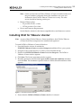

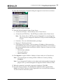
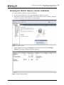
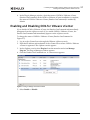
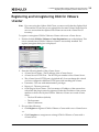

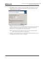
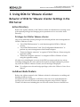

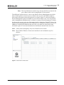
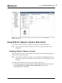
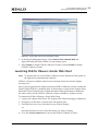

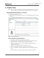
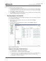
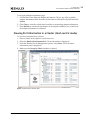
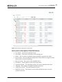
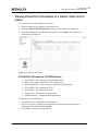
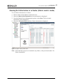
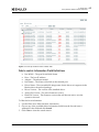
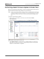
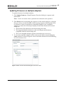
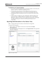
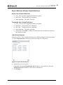


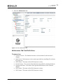


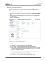
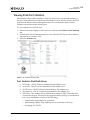
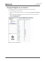
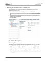
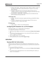
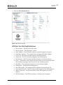
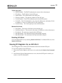
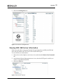
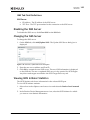
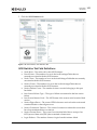

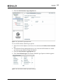


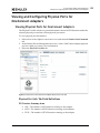
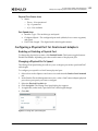
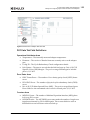
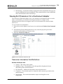


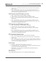


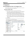


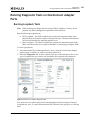


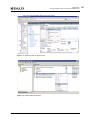
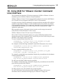


![OverView Control Manager user`s manual - operator [v04]](http://vs1.manualzilla.com/store/data/005659468_1-4c522981c7089838b286d7fbb1120c24-150x150.png)