1
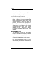
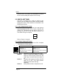
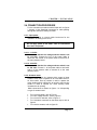
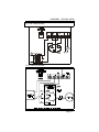
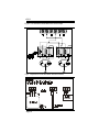
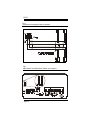
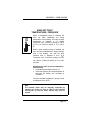
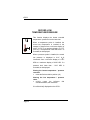
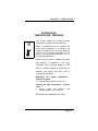
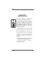
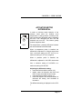
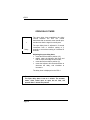
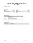
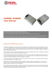
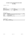
CPS-1
USER’S MANUAL
AIR INLET / CURTAIN CONTROL
temperature / static pressure
AL
Clo
DE
Y
LA
HI
F2
A LA
OPEN
LO
LAY
DE
RM
Opn
A
DIF F
RM
CLOSE
ADJUST
Varifan +
®
CPS-1
CPS-1
Although the manufacturer has made every effort to
ensure the accuracy of the information contained herein,
this document is subject to change without notice due to
ongoing product development.
WARNING AND PRECAUTIONS
Equipment , probe failure, blown fuses and/or tripped
breakers may prove harmful to the contents of the
building. Therefore it is strongly recommended to install
backup devices and alarm or warning devices. Spare
equipment should also be available at the owner’s site.
Equipment manufactured by the manufacturer is
protected against normal line surges. High surges caused
by thunder storms or power supply equipment may
damage this equipment. For added security against line
voltage surges it is recommended that surge and noise
suppression devices be installed at the electrical
distribution panel. Use of shielded cable for probes is
recommended for protection against lightning. These
devices are available from most electrical supply
distributors.
RECOMMENDATIONS
The manufacturer recommends that all installation
procedures described herein be performed by a qualified
electrician or installation technician. Further more the
manufacturer recommends to test all the functions and
equipment connected to the CPS, including the alarm
system and backup devices, after installation, after
change to the installation and once a month after that.
Fuse verification and replacement, as well as the proper
setting of control values shall be the responsibility of the
owner of this equipment.
Page 2
TABLE OF CONTENTS
CHAPTER 1 - INTRODUCTION
1.
1.1
General ...........................................................................5
Description .......................................................................5
Definition of terms .........................................................................7
CHAPTER 2 - INSTALLATION
2.1
2.2
2.3
2.3.1
2.3.2
2.4
2.4.1
2.4.1.1
2.4.1.2
2.4.2
2.5
2.5.1
2.5.2
2.5.3
2.6
2.7
Unpacking ........................................................................9
Mounting .........................................................................9
Switch Settings................................................................10
Line Voltage Selector Switch ..........................................10
Software Settings DIP Switch .........................................10
Connection Procedure ....................................................11
Input Power .....................................................................11
115 VAC ..........................................................................11
230 VAC ..........................................................................11
Actuator Motor.................................................................11
Temperature / Static pressure Sensor ............................12
Single Temperature Probe ..............................................12
Temperature Averaging ..................................................12
Static Pressure Sensor ...................................................12
Alarm ...............................................................................13
Powering Up....................................................................14
CHAPTER 3 - USER GUIDE
LED Status Window ........................................................19
Control Dials....................................................................19
PRIMARY FUNCTIONS
Main Set Point Temperature / Pressure ..........................21
Open Run Timer..............................................................22
Close Run Timer .............................................................23
Record Low Temperature / Pressure ..............................24
Record High Temperature / Pressure .............................25
Temperature / Pressure Display .....................................26
Page 3
CPS-1
SECONDARY FUNCTIONS
Actuator Motor Differential ..............................................27
Open Delay Timer ...........................................................28
Close Delay Timer...........................................................29
Low Temperature Alarm..................................................30
High Temperature Alarm .................................................31
APPENDIX
Troubleshooting ..............................................................32
Specifications ..................................................................33
Record Form ...................................................................34
Page 4
CHAPTER 1 - INTRODUCTION
1. GENERAL
This document provides a description of the CPS-1 control
panel. This document is organized as follows:
•
•
•
•
Introduction
Installation
User’s Guide
Appendix
1.1 DESCRIPTION
Congratulations on the purchase of your CPS-1
environmental control system. The CPS-1 provides you
with full control over static pressure and air flow resulting in
a comfortable environment for your livestock.
The CPS-1 provides microprocessor control over one
stage. The stage regulates the static pressure of a room
via the use of actuator motors which in turn control the
building’s air inlet baffle boards or air inlet curtains. The
CPS-1 can either use temperature (with temperature probe
2004-1k) or for greater accuracy static pressure (with static
pressure sensor model # SPS-1) as a means to control the
opening of the air inlet baffle/curtain.
The CPS-1 provides you with full control over its stage via
the use of an easy to follow display panel. All
programmable features can be customized to meet your
requirements.
The CPS-1 has programmable temperature and static
pressure set points which are the base point for the control
of an actuator motor. The delay time before the actuator
motors start to run, as well as the period of time it operates
for are fully programmable.
The CPS-1 keeps you constantly informed by displaying
the status of its output as well as the ambient temperature
or static pressure levels.
Safety of livestock is ensured by the continuous control of
climate and timely alarm notification should environmental
conditions exceed alarm set points. Further security may
be obtained by connecting all CPS series controls in a
Page 5
CPS-1
network
configuration to an optional RCM-40 remote monitoring
unit. This provides remote control monitoring of each room.
All programmable settings are maintained indefinitely
whether or not the CPS-1 is powered.
With CPS-1 in control of your climate, you are assured of
optimal living conditions for your livestock.
Page 6
CHAPTER 1 - INTRODUCTION
DEFINITION OF TERMS
MAIN SET POINT
The desired room temperature or pressure.
ROOM TEMPERATURE / PRESSURE
The actual temperature / pressure of the room.
(also called ambient temperature in the manual)
AIR INLET BAFFLE BOARD/AIR INLET
CURTAIN
A device which regulates air flow into a building by
controlling the opening or closing of an air passage.
Page 7
CPS-1
Page 8
CHAPTER 2 - INSTALLATION
The manufacturer recommends that the installation
instructions which follow be adhered to as closely as
possible, and all work be performed by a certified
electrician. Failure to do so may void the warranty!
2.1 UNPACKING
Unpack the CPS-1 from its box and inspect contents for
damage. Should the contents appear to be damaged,
contact your local distributor for return material procedures.
The package should contain the following standard items:
• 1 CPS-1 control.
• 1 installed temperature probe (model number 20041K).
• 2 cable fasteners.
The following optional items may be included:
• 3 additional temperature probes for temperature
averaging.
• 1 SPS-1 static pressure sensor.
2.2 MOUNTING
Mount the CPS-1 to the wall using the mounting holes
located on the flange of the control housing.
To limit the unit’s exposure to noxious gases install the
unit in a hallway.
Make certain that the unit is mounted right side up with
the cable entry holes facing down.
The CPS-1 will operate in a temperature range of 42°F 111 °F (5.5 °C - 44 °C).
The enclosure is watertight, it is not splash proof or
immersion proof. DO NOT WATER the control. Cover
carefully with plastic when you are clean the room.
* It is prohibited to use overhead cables outside the
building.
Mounting hardware is not shipped with the unit.
Page 9
CPS-1
Once the CPS-1 is in place, use a screwdriver to remove
the four screws holding the faceplate to the housing.
2.3 SWITCH SETTINGS
The CPS-1 is configured for a variety of options via two
switches: the line voltage selector switch, and the software
settings DIP switch. These switches are described in the
following two sections.
2.3.1 - Line Voltage Selector Switch
This switch is located on the surface of the main (bottom)
board and adapts the CPS-1 for 115 VAC or 230 VAC line
voltage. The manufacturer set the switch to 230 VAC. If
you wish to use it on 115 VAC you have to select to 115
VAC before turning on the power
230V
115V
Refer to Figures 1 through 4.
2.3.2 - Software Settings DIP Switch
This switch is located at the rear of the CPS-1 faceplate
and adjusts the following options.
OFF
ON
OFF
1
2
3
4
Fahrenheit
Settings locked
High static pressure sensitivity
Temperature mode
Switch 1
Switch 2
Switch 3
Switch 4
Page 10
ON
Celsius
Setting unlocked
Normal static pressure sensitivity
Pressure mode
Fahrenheit or Celsius display on the CPS-1.
Locks or unlocks your settings. All settings
except for main set point, record low, and
record high are locked while this switch is
off.
Increases static pressure sensitivity with DIP
switch set to OFF. (The static pressure
reading will react faster with High
sensitivity).
Static pressure mode or temperature mode.
CHAPTER 2 - INSTALLATION
2.4 CONNECTION PROCEDURE
For the connection procedures which follow refer to figures
1 through 4. Use watertight connectors for cable passing
through the enclosure, sealing or rubber.
2.4.1 - Input power
Use a screwdriver to remove cable knock-outs for the
installation of cabling to the CPS-1.
Do not apply power to the CPS-1 until all connections
have been completed!
2.4.1.1 - 115 VAC
Make certain that the line voltage selector switch is set
to 115 VAC. Connect the live of the power cable to
terminal 9 and neutral of the power cable to terminal 8 on
the main (bottom) board.
2.4.1.2 - 230 VAC
Make certain that the line voltage selector switch is set
to 230 VAC. Connect L1 of the power cable to terminal 9
and L2 of the powers cable to terminal 8 on the main
(bottom) board.
2.4.2 - Actuator motor
Stage 1 provides two dry contacts which control a linear
actuator motor used to operate an air inlet baffle board or
air inlet curtain. One dry contact is used to operate the
motor winding which reduces the air opening, and one dry
contact is used to operate the motor winding which
increases the air opening.
Make connections as shown on figures 1 to 4 depending
on type of actuator used:
•
•
•
•
•
For a 3 wire actuator, refer to Figure 1.
For a low voltage actuator, refer to Figure 2.
For a 2 wire DC actuator, refer to Figure 3.
For 2 actuators connected on the same output, refer to
figure 4.
For a 4-wire actuator, refer to figure 5a
Page 11
CPS-1
2.5 TEMPERATURE PROBES / STATIC
PRESSURE SENSORS
Temperature probe and static pressure sensor use a
“Class 2” low voltage circuit. Their cable can be extended
up to 500 feet (150 meters). For probe longer than 10
feet (3 meters), install shielded wire #18AWG min. With
the shield grounded to ground of power source.
Single probe temperature and static pressure connections
are illustrated in Figure 5 while temperature probe
averaging connections are illustrated in Figure 6.
2.5.1 Single Temperature Probe
Use shielded cabling for probes when their cable paths
run parallel to high voltage wires. Connect the shields to
the ground of power source. Failure to do so may result
in inaccurate readings!
Install a single temperature probe in an area that best
reflects the overall temperature of the room.
Connect the two leads of the temperature probe to the
CPS-1 terminals labelled IN1 and GND as indicated in
Figure 5.
2.5.2 Temperature Averaging
Four temperature probes are required if temperature
averaging is desired in larger rooms. Place the probes in
locations that best reflect the ambient temperature. Refer
to Figure 6.
2.5.3 Static Pressure Sensor
To properly position a SPS-1 static pressure sensor inside
the building refer to the installation manual supplied with
the unit. Important: disconnect temperature probe,
when the static pressure sensor is used.
Connect the static pressure probe to the CPS-1 terminals
labeled IN1, PWR, and GND as indicated in Figure 5.
Page 12
CHAPTER 2 - INSTALLATION
2.6 ALARM
The CPS-1 provides a normally open and normally closed
dry contact for alarming low or high temperature
conditions. In addition, this same contact can be used to
signal a power failure. This contact may be connected to
an alarm system, or directly to a siren and/or auto-dialer.
Momentary power interruptions may trigger false alarms!
To avoid false alarming when the CPS-1 is connected to
an alarm system, install a time delay relay between the
CPS-1 and the alarm system.
Make connections as indicated in Figure 3.
Alarm goes off when set to “manual” or “off”; Since the
CPS-1 works with relative set point, it is imminent that the
CPS-1 will recognize a HI or LO alarm when the main set
point is changing to either “Opn”, “Clo” or “OFF”. But when
the selection reaches one these positions, the CPS-1
acknowledges that it is in manual and it will close the alarm
relay as it does in normal situation. Therefore, during the
process of going in manual, the alarm will go off
momentarily.
The alarm relay is also used to interface with a computer
network (via RCM-40). The CPS-1 requires a minor
modification on its bottom card to differentiate the mode of
operation. At the factory the unit is set to work on the alarm
mode, to change it to the network mode the jumpers on
terminal H1 located at the upper left corner of the bottom
card shall be modified. The jumpers are included with the
RCM-40. Refer to figure 7.
Page 13
CPS-1
2.7 POWERING UP
Before powering up the CPS-1, attach the faceplate to the
casing of the CPS-1 using the four screws previously
removed.
Set Selector knob to position (12).
Upon power up, the unit will test its display by briefly
lighting all the segments of its LED. Make certain that all
segments light.
Following the LED display test, the unit displays the
ambient temperature or pressure of the room.
If the temperature or pressure is not displayed, refer to the
Trouble Shooting section in the appendix of this document.
Fig.1
3 Wire Actuator
Com.
Close
Open
Page 14
CHAPTER 2 - INSTALLATION
Fig 2 Low Voltage Actuator
Fig 3 2 Wire DC Actuator
Page 15
CPS-1
Fig 4a Two actuators connected on the same output
Fig 5 Temperature Probe and Static Pressure Sensor
Page 16
CHAPTER 2 - INSTALLATION
Fig 5a 4 wire actuator
1
Note for Figures 1 through 7.
Power cut and protection devices in case of overload.
2
3
4
Actuator motors require a limit switch.
If motor runs in reverse, switch terminal #5 with terminal #7.
Not furnished with the unit.
Connect to ground wire of power source.
Page 17
CPS-1
Fig 6
Temperature Averaging Probe Connection
Fig 7
Main Board: Terminal Blocks, Switch, and Jumpers
Page 18
CHAPTER 3 - USER’S GUIDE
AIR INLET / CURTAIN CONTROL
temperature / static pressure
AL
Clo
DE
Y
LA
HI
F2
OPEN
LO
AY
DEL
ALAR
M
Opn
A
DI FF
RM
CLOSE
ADJUST
Varifan +
®
CPS-1
The CPS-1 front panel shown above features a LED status
window and two control dials which are respectively used
to select a function and adjust a setting.
LED Status Window
The LED status window features a 3 digit LED readout for
the display of temperature in Fahrenheit or Celsius,
pressure level, and programmable settings.
In addition, the LED status window displays the operational
status of stage 1 via two additional LEDS (shown above in
LED window) that indicate the opening or closing of the air
inlet / baffle board. When illuminated, each LED indicates
that the actuator motor is operating. A third LED is an
alarm indicator.
Control Dials
The center dial is the Selector dial and is used to select
one of the CPS-1’s 6 primary or 5 secondary functions.
The dial located to the right of the Selector dial is the
Adjustor dial and is used to adjust the setting of each function or to enter secondary function mode.
The 6 primary functions are:
• 1 Main temperature / pressure set point
• 2 Open run timer
• 3 Close run timer
Page 19
CPS-1
•
•
•
10 Record low temperature / pressure
11 Record high temperature / pressure
12 Ambient temperature / pressure display
Any one of these primary functions is selected by rotating
the Selector dial to the corresponding number and
associated graphical image printed on the faceplate of the
panel. When primary functions 1 through 3 and 10 and 11
are selected, the LED status window displays a blinking
value. Function 12 displays ambient temperature or static
pressure levels.
The 5 secondary functions are:
• 1 Differential
• 2 Open delay timer
• 3 Close delay timer
• 10 Low temperature / pressure alarm
• 11 High temperature / pressure alarm
Select any one of these secondary functions by:
• rotating the Selector dial to (12)
• rapidly rotating the Adjustor dial back and forth to enter
secondary mode.
• rotating the Selector dial from function (12) to any other
secondary function.
When secondary functions 1 through 3, and 10 and 11 are
selected, the status window displays a blinking value along
with a scrolling LED display. Selection of function 12
removes the CPS-1 from the secondary function mode.
Page 20
CHAPTER 3 - USER’S GUIDE
MAIN SET POINT
TEMPERATURE / PRESSURE
1
When a temperature probe is installed, the
main set point establishes the target
temperature in the building. The main set point
temperature is adjusted in 0.5 degree
increments from a minimum setting of 42.0°F
(5.5°C) to a maximum setting of 111°F (44.0°
C).
When a static pressure probe is installed, the
main set point establishes the target pressure
level in the building. The main set point
pressure level is adjusted in 0.01" H2O
increments from a minimum setting of OPN,
0.0" H2O to a maximum setting of 0.14" H2O,
and CLO.
Adjusting the main set point temperature /
pressure level:
• rotate the Selector dial to position (1),
• rotate the Adjustor dial counterclockwise to
decrease the setting, and clockwise to
increase it.
The main set point temperature / pressure level
is displayed on the CPS-1.
Note:
The actuator motor may be manually controlled by
adjusting the main set point to OPN or CLO thereby
causing the air inlet to either remain fully open or
closed.
Page 21
CPS-1
OPEN RUN TIMER
The open run timer establishes the period of
time that the actuator motor operates when it
receives the command to open an air inlet
baffle board or air inlet curtain.
OPEN
The open run timer is adjusted in 1 second
increments from a minimum setting of 1 second
to a maximum setting of 1 minute 59 seconds.
Adjusting the open run timer:
• rotate the Selector dial to position (2),
• rotate the Adjustor dial counterclockwise to
decrease the setting, and clockwise to
increase it.
The open run timer setting is displayed on the
CPS-1.
Example:
The open run timer is set to 30 seconds. When the
control determines that the air inlet must open, the command to the motor is sent after the delay set by
secondary function (2) has expired. The actuator motor
will operate for 30 seconds before stopping.
Page 22
CHAPTER 3 - USER’S GUIDE
CLOSE RUN TIMER
The close run timer establishes the period of
time that the actuator motor operates when it
receives the command to close an air inlet
baffle board or air inlet curtain.
CLOSE
The close run timer is adjusted in 1 second
increments from a minimum setting of 1 second
to a maximum setting of 1 minute 59 seconds.
Adjusting the close run timer:
• rotate the Selector dial to position (3),
• rotate the Adjustor dial counterclockwise to
decrease the setting, and clockwise to
increase it.
The close run timer setting is displayed on the
CPS-1.
Example:
The close run timer is set to 30 seconds. When the
control determines that the air inlet must close, the command to the motor is sent after the delay set by
secondary function (3) has expired. The actuator motor
will operate for 30 seconds before stopping.
Page 23
CPS-1
RECORD LOW
TEMPERATURE/PRESSURE
This function displays the lowest recorded
temperature / pressure since the last clear.
When a temperature probe is installed, the
record low temperature is rounded to the
nearest 0.5 degree from a minimum display of
42.0°F (5.5°C) to a maximum display of 111°F
(44.0°C). If a temperature lower than 42.0°F is
recorded, Lo is displayed.
When a pressure probe is installed, the record
low pressure is displayed in 0.01" H2O
increments from a minimum display of -0.20"
H2O to a maximum display of 0.20" H2O. If a
pressure level lower than - 0.20" H2O is
recorded, Lo is displayed.
Viewing the lowest temperature / pressure
recorded:
• rotate the Selector dial to position (10)
Clearing the low temperature / pressure
value:
• quickly rotate the Adjustor dial
counterclockwise, then clockwise.
CLr will be briefly displayed on the CPS-1.
Page 24
CHAPTER 3 - USER’S GUIDE
RECORD HIGH
TEMPERATURE / PRESSURE
This function displays the highest recorded
temperature / pressure since the last clear.
HI
When a temperature probe is installed, the
record high temperature is rounded to the
nearest 0.5 degree from a minimum display of
42.0°F (5.5°C) to a maximum display of 111°F
(44.0°C). If a temperature higher than 111°F is
recorded, Hi is displayed.
When a pressure probe is installed, the record
high pressure is displayed in 0.01" H2O
increments from a minimum display of -0.20"
H2O to a maximum display of 0.20" H2O. If a
pressure level higher than 0.20" H2O is
recorded, Hi is displayed.
Displaying the highest temperature
pressure recorded:
• rotate the Selector dial to position (11)
/
Clearing the high temperature / pressure
value
• quickly rotate the Adjustor dial
counterclockwise, then clockwise.
CLr will be briefly displayed on the CPS-1.
Page 25
CPS-1
TEMPERATURE
PRESSURE DISPLAY
This function displays the ambient room
temperature or static pressure of the room.
If a temperature probe is installed, the ambient
temperature is displayed to the nearest 0.5
degree from a minimum display of 42.0°F (5.5°
C) to a maximum display of 111°F (44.0°C). If
the temperature is lower than 42.0°F, Lo is
displayed. If the temperature is higher than
111°F, Hi is displayed.
If a static pressure probe is installed, the static
pressure is displayed to the nearest 0.01" H2O
from a minimum display of -0.20" H2O to a
maximum display of 0.20" H2O. If the pressure
is lower than -0.20" H2O, Lo is displayed. If the
temperature is higher than 0.20" H2O, Hi is
displayed.
Viewing the ambient temperature / pressure:
• rotate the Selector dial to position (12)
The ambient temperature
displayed on the CPS-1.
Page 26
/
pressure
is
CHAPTER 3 - USER’S GUIDE
ACTUATOR MOTOR
DIFFERENTIAL
In order to minimize erratic behavior of the
actuator motor when the ambient room
temperature or static pressure is exactly at the
main set point, the differential setting separates
this ON / OFF threshold into two: one ON
threshold and one OFF. This feature greatly
reduces equipment wear.
DIFF
The temperature / pressure difference between
the two thresholds is the differential.
When a temperature probe is installed, the
differential is adjusted in 0.5 degree increments
from a minimum setting of 0.0°F (0.0°C) to a
maximum setting of 16°F (8°C) degrees.
When a pressure probe is installed, the
differential is adjusted in 0.01"H2O increments
from a minimum setting of 0.00"H2O to a
maximum setting of 0.05"H2O.
Adjusting the differential setting:
• rotate the Selector dial to position (12),
• rapidly rotate the Adjustor dial back and
forth to enter secondary function mode,
• rotate the Selector dial to position (1),
• rotate the Adjustor dial counterclockwise to
decrease the setting, and clockwise to
increase it.
The differential setting is displayed on the CPS1.
Page 27
CPS-1
OPEN DELAY TIMER
The open delay timer establishes the delay
interval between the time the control
determines that an actuator motor should open,
and the time that the signal is actually sent.
Delay
The open delay timer is adjusted in 5 second
increments from a minimum setting of 5
seconds, to a maximum setting of 9 minutes 55
seconds.
Adjusting the open delay timer:
• rotate the Selector dial to position (12),
• rapidly rotate the Adjustor dial back and
forth to enter secondary function mode,
• rotate the Selector dial to position (2),
• rotate the Adjustor dial counterclockwise to
decrease the delay, and clockwise to
increase it.
The delay timer is displayed on the CPS-1.
Example:
The open delay timer is set to 1 minute. The actuator
motor, when called upon to open the air inlet, will
operate after 1 minute has passed.
Page 28
CHAPTER 3 - USER’S GUIDE
CLOSE DELAY TIMER
The close delay timer establishes the delay
interval between the time the control
determines that an actuator motor should close,
and the time that the signal is actually sent.
Delay
The close delay timer is adjusted in 5 second
increments from a minimum setting of 5
seconds, to a maximum setting of 9 minutes 55
seconds.
Adjusting the close delay timer:
• rotate the Selector dial to position (12),
• rapidly rotate the Adjustor dial back and
forth to enter secondary function mode,
• rotate the Selector dial to position (3),
• rotate the Adjustor dial counterclockwise to
decrease the delay, and clockwise to
increase it.
The delay timer is displayed on the CPS-1.
Example:
The close delay timer is set to 1 minute. The actuator
motor, when called upon to close the air inlet, will
operate after 1 minute has passed.
Page 29
CPS-1
LOW TEMPERATURE / PRESSURE ALARM
This function establishes the temperature /
pressure difference below the main set point
that the room can reach before a low
temperature alarm is signalled. When a low
temperature / pressure alarm occurs the alarm
relay is activated and the alarm LED lights on
the CPS-1.
Alarm
When a temperature probe is installed the low
temperature alarm is adjusted in 0.5 degree
increments from a minimum setting of -30.0°F
(-18.0°C) to a maximum setting of 0.0°F (0.0°C)
When a pressure probe is installed the low
pressure alarm is adjusted in 0.01" H2O
increments from a minimum setting of -0.10"
H2O to a maximum setting of 0.00 " H2O.
Adjusting the low temperature / pressure
alarm setting:
• rotate the Selector dial to position (12),
• rapidly rotate the Adjustor dial back and
forth to enter secondary function mode,
• rotate the Selector dial to position (10),
• rotate the Adjustor dial counterclockwise to
decrease the setting, and clockwise to
increase it.
The low temperature alarm setting is displayed
on the CPS-1.
Page 30
CHAPTER 3 - USER’S GUIDE
HIGH TEMPERATURE / PRESSURE ALARM
This function establishes the temperature /
pressure difference above the main set point
that the room can reach before a high
temperature / pressure alarm is signalled.
When a high temperature / pressure alarm
occurs the alarm relay is activated and the
alarm LED lights on the CPS-1.
Alarm
When a temperature probe is installed the high
temperature / pressure alarm is adjusted in 0.5
degree increments from a minimum setting of
0.0°F (0.0°C) to a maximum setting of 30.0°F
(18.0°C).
When a pressure probe is installed the high
pressure alarm is adjusted in 0.01" H2O
increments from a minimum setting of 0.0
" H2O to a maximum setting of 0.10 " H2O.
Adjusting the high temperature / pressure
alarm setting:
• rotate the Selector dial to position (12),
• rapidly rotate the Adjustor dial back and
forth to enter secondary function mode,
• rotate the Selector dial to position (11),
• rotate the Adjustor dial counterclockwise to
decrease the setting, and clockwise to
increase it.
The high temperature alarm setting is displayed
on the CPS-1.
Page 31
CPS-1
TROUBLESHOOTING
SYMPTOM
CAUSE and REMEDY
Lo is
continually
displayed
−
Hi is
continually
displayed
−
Actuator
motor is not
operating
−
Verify whether the appropriate stage
LED is on yet the actuator motor is not
operating. Verify wiring and device
Display is
blank
−
Verify that the line voltage selector
switch is properly set.
Verify that the 10 pin flat cable
between the main board and the
faceplate board is properly connected.
−
−
−
Page 32
Temperature or pressure is below
minimum.
Probe is disconnected or defective.
Temperature or pressure is above
maximum.
Probe is short circuited.
APPENDIX
SPECIFICATIONS
DESCRIPTION
VALUE
INPUT POWER
−
−
−
6W
115/230 VAC
50 / 60 Hz
STAGE 1 (relay 1 and 2)
Not Fused
−
−
−
−
−
10 AMP ; 115V/230V
1/2 HP @ 115V
1 HP @ 230V
Min. Rating 10mA at 115V*
20mA at 230V*
ALARM (dry relay
contact)
−
6 AMP; 30V AC/DC
* Relay will not function properly if load is smaller than
the min. value.
Storage
temperature:
0 to 70°C (32 to 158°F)
Operation
temperature:
0 to 50°C (32 to 122°F)
Weight:
1 Kg (2.2 pounds)
Dimension:
97x163x145mm (3.80x6.40x5.70”)
Page 33
CPS-1
RECORD FORM
Dial Option
1
Default setting
Main Set Point
77°F
25°C
0.02” H2O
2
Open Run Timer
3
Close Run Timer
24%
3 seconds
24%
3 seconds
2nd Function
1
Actuator Motor Differential
2.0°F
1.0°C
0.02” H2O
2
Open Delay Timer
2
2
2 minutes
3
Close Delay Timer
10
Lo Temperature/Pressure Alarm
-9.0°F
11
Hi Temperature/Pressure Alarm
20.0°F
2 minutes
-5.0°C
-0.05” H2O
12.0°C
0.05” H2O
Page 34
User setting
Limited Warranty
The manufacturered equipment and supplied
components have gone through rigorous inspection to
assure optimal quality of product and reliability.
Individual controls are factory tested under load,
however the possibility of equipment failure and/or
malfunction may still exist.
For service, contact your local retailer or supplier. The
warranty period shall be for two years from
manufacturing date. Proof of purchase is required for
warranty validation.
In all cases, the warranty shall apply only to defects in
workmanship and specifically exclude any damage
caused by over-voltage, short circuit, misuse, acts of
vandalism, fortuitous events, acts of God, flood, fire,
hail, lightning or any other natural disaster. Any
unauthorized work, modification or repair on this
product automatically voids the warranty and
disclaims the manufacturer from all responsibility.
The manufacturer assumes only those obligations set
forth herein, excluding all other warranties or
obligations. This warranty stipulates that in all cases
the manufacturer shall be liable only for the supply of
replacement parts or goods and shall not be liable for
any personal injury, damages, loss of profits,
interrupted operations, fine contravention of the law or
damages to the production of the PURCHASER and
the PURCHASER shall take up the defense and hold
the manufacturer faultless regarding any legal or
extra legal proceedings, notice, or claim by the
customer or by a third party, and regarding any legal
and extra legal expenses and fees brought forward on
by such damages.
Page 35
MAV CPS-1 Ver: 3.1
Rev. 04 juin 2001
2-wire DC actuator