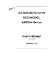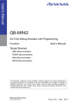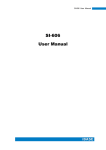
1
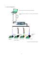
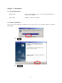
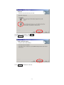
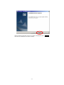
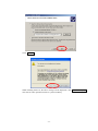
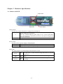
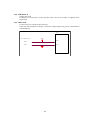
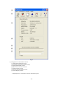
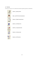
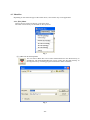
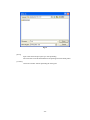
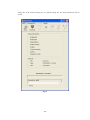
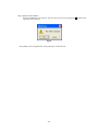
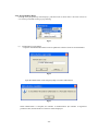
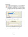
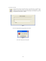
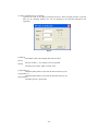
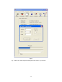
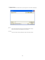
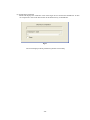
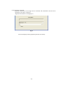
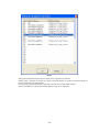
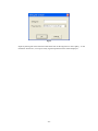
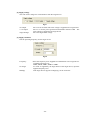
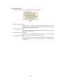
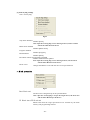
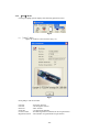
Programmer for flash micro computers
User’s Manual
TESSERA Technology INC.
6th edition 9/2008
Table of Contents
Chapter 1 Summary······································································································2
1.1 System Configuration ····························································································3
Chapter 2 Installation····································································································4
2.1 System Requirement······························································································4
2.2 Software Installation ·····························································································4
2.3 Driver Installation ································································································7
Chapter 3 Hardware Specifications ················································································· 11
3.1 Switches and LED······························································································· 11
3.2 Target Interface Connector Specifications································································· 12
3.3 Target Cables····································································································· 13
3.4 Extension Adaptor ······························································································ 14
3.5 FP4 Adaptor······································································································ 15
3.6 Target Board Cautions ························································································· 16
3.6.1 RESET ······································································································· 16
3.6.2 FLMD0······································································································· 17
3.6.3 SO/TxD, SI/RxD/DGCLK, SCK and H/S ···························································· 18
3.6.4 CLK/DGCLK ······························································································ 20
3.6.5 VDD, GND ·································································································· 20
3.7 Basic Specification ······························································································ 21
Chapter 4 StickWriter Operation using GUI Software ························································· 22
4.1 Launching GUI Software······················································································ 22
4.2 Tool Bar ··········································································································· 24
4.3 Menu Bar ········································································································· 25
4.3.1 [File] Menu·································································································· 25
4.3.2 [Programmer] Menu ······················································································ 38
4.3.3 [Device] Menu ······························································································ 42
4.3.4 [Help]Menu ···························································································· 63
Chapter 5 Additional License ························································································ 64
-1-
Chapter 1 Summary
StickWriter is a compact and lightweight type of flash writer used to write program data into a
micro-computer with built-in flash memory.
It allows for both “on-board writing” in which the micro-computer is implemented on a customer-built
board, or “off-board writing” in which the device is mounted on the IC socket of our SS board.
Since the 32-MByte flash memory is built into the body of the StickWriter, it allows the HEX files and
the parameter files for each device to be saved. Therefore, “stand-alone operation” is possible, without
requiring a PC when programming.
When operating as a “stand-alone” system, complete stand-alone operation is possible without requiring
external power for the StickWriter.
-2-
1.1 System Configuration
Windows Personal Computer (Windows2000/XP)
Connect to the PC directly or by using a USB extension
cable*1
DF11
Connector
Direct
connection
DF11
Connector
Pin Header
1
1
Extension cable*
Extension cable*
+
1
Extension adaptor*
Connector for
PG-FP4
1
FP4 Conversion adaptor*
*1:Attachment for Standard Package
-3-
Chapter 2 Installation
2.1 System Requirement
Host Machine
To use the StickWriter GUI, a PC running Windows2000 or
Windows XP is required.
Host Interface
USB(Rev1.1/2.0) port is required.
2.2 Software Installation
After inserting the StickWriter Installation CD into the CD drive, the following installer is launched
automatically.
Click
OK
.
Click
Next > .
-4-
To change the install folder, click Custom.
Click Next > . Installation will start.
Click
Install
. Installation will start.
-5-
When installation finishes, the above window is displayed. Click
The GUI for StickWriter has been installed.
-6-
Finish .
2.3 Driver Installation
When StickWriter is first connected, the “New Hardware Detection Wizard” will be launched.
Since the driver for the StickWriter is not registered in Windows Update, select “No” and
click Next> .
Select “Install from a list or specific location(Advanced)”, and click
-7-
Next> .
Check the “Include this location in the search:” and click
Browse .
Select the “DRIVER” folder located in the folder where StickWriter was installed.
-8-
Click
Next> .
While installing the driver, the above message will be displayed. Click
This will not cause operation failure or system instability.
-9-
Continue Anyway .
The driver installation is finished. Click
- 10 -
Finish .
Chapter 3 Hardware Specifications
3.1 Switches and LED
Output switch
Status LED
Power Switch
Output Switch
Specifies the voltage when power is supplied to the StickWriter.
Approximately 5V Output (max 400mA).
Outputs USB power from the PC.
5
Note: In a standard USB, the power range is 4.75 - 5.25V (on the Host
side). Also diodes are contained for protection, so the power voltage drops
to 0.36V at maximum.
3
Output 3.3V (max 250mA).
Power Switch
Specifies source of power supply to the StickWriter.
U
Supplied by the USB.
T
Supplied by the target. The target voltage should be within 3.3V to 5V.
Status LED
The status is shown on an LED display under the Power switch.
The light turns on when power is supplied to the StickWriter.
P
Blue The light turns on when communicating with the PC or with the
Power
target device.
F
The light turns on when communication with the target device
Red
Fail
fails.
S
The light turns on when a command to the target device is
Blue
successful.
Success
- 11 -
3.2 Target Interface Connector Specifications
(1)
(9)
(2)
Pin No
[1]
[2]
(10)
StickWriter Signal Name
GND
Connection Point with Target CPU
VSS
RESET
RESET
[3]
SI/RxD/DGDATA
[4]
[5]
[6]
[7]
[8]
[9]
[10]
VDD
SO/TxD
FLMD0
SCK
H/S
CLK/DGCLK
Reserved
SO or TxD or DGDATA(X2)
or TOOL0
VDD
SI or RxD
FLMD0
SCK
P??(HS)
X1 or DGCLK(X1)
StickWriter Side Connector Type No: DF11-10DP-2DS (Hirose Electronics)
Appropriate Target Side Connectors:
SMT Type
DIP Type
Insulation Displacement Socket
Clamping Socket
- 12 -
DF11CZ-10DS-2V
DF11-10DS-2DSA
DF11-10DS-2R26
DF11-10DS-2C
3.3 Target Cables
[1]
Cape Specifications
Black GND
Display Specifications
1, GND
[2]
Brown
2, RESET
RESET
[3]
Orange
SI/RxD/DGDATA
3, SI/RxD/DGDATA
[4]
[5]
[6]
[7]
[8]
[9]
[10]
Red
Yellow
Green
Blue
Purple
White
VDD
SO/TxD
FLMD0
SCK
H/S
CLK/DGCLK
4, VDD
5, SO/TxD
6, FLMD0
7, SCK
8, H/S
9, CLK/DGCLK
None
Connection Point with Target CPU
VSS
RESET
SO or TxD or DGDATA(X2)
or TOOL0
VDD
SI or RxD
FLMD0
SCK
P??(HS)
X1 or DGCLK(X1)
Appropriate Header Pin Specifications: 0.64mm Length: 6mm
Recommended Connector: PS Series (Japan Aviation Electronics Industry, Limited.)
- 13 -
3.4 Extension Adaptor
An adaptor used for connecting through a target cable if StickWriter cannot connect due to implications of
the framework, etc. Please connect all of the 9 cables, connecting pin1 of the pin header to pin1 of the target
cable.
- 14 -
3.5 FP4 Adaptor
An adaptor used for converting to a connector for NEC Electronics PG-FP4.
When using SW-1, turn both 1 and 2 ON.
When using 78K0S/Kx1+ series, such as DGDATA and DGCLK, turn both 1 and 2 OFF.
When using 78K0R series, such as TOOL0, turn 1 ON and 2 OFF.
SW-1
1
2
Others
ON
ON
78K0S/Kx1+
OFF
OFF
- 15 -
78K0R
ON
OFF
3.6 Target Board Cautions
3.6.1 RESET
When StickWriter wants to reset the target CPU, it outputs “Low”.
When StickWriter wants to cancel the reset, it changes to “Hi-Z”.
When there is no external reset circuit
CPU
VDD
R
StickWriter
RESET
RESET
When there is an external reset circuit
CPU
VDD
R
StickWriter
RESET
RESET
RESET CIRCUIT
Open-Collector or Open-Drain Output
Set the external reset circuit as Open-Collector or Open-Drain output. Set the Wired OR
Connection with the reset signal from StickWriter. Be sure that reset will not occur while
writing to the target CPU from StickWriter. Be cautious when using an external watch-dog
timer.
- 16 -
3.6.2 FLMD0
A pulse is output from StickWriter to determine the communication method.
Perform the “pull-down” process on the target board.
The “pull-down” processing is unnecessary in the device of 78K0R series because
there is “pull-down resistance” in the inside.
If the target CPU has an FLMD1 port, perform the “pull-down” process and maintain “Low”
level while StickWriter is being connected.
CPU
FLMD1
R
StickWriter
FLMD0
FLMD0
R
- 17 -
3.6.3 SO/TxD, SI/RxD/DGCLK, SCK and H/S
The StickWriter is in communication with the target CPU.
When external devices are connected to the ports, be cautious not to inhibit communication.
Keep in mind that external devices may malfunction due to communication data with the
StickWriter.
It is not necessary to perform processes for unused ports on StickWriter.
SO/TxD
SI/RxD/DGDATA
SCK
H/S
Output from StickWriter
Output from Target CPU for SI/RxD.
Input/Output for DGDATA/TOOL0.
Output from StickWriter
Output from Target CPU
For clock-synchronized communication (H/S is optional)
CPU
StickWriter
SI
SO/TxD
SO
SI/RxD/DGDATA
SCK
SCK
H/S
P??
For UART communication
CPU
StickWriter
RxD
SO/TxD
TxD
SI/RxD/DGDATA
- 18 -
For Single Wire UART
CPU
StickWriter
CLK/DGCLK
X1
SI/RxD/DGDATA
X2
CPU
StickWriter
TOOL0
SI/RxD/DGDATA
- 19 -
3.6.4 CLK/DGCLK
Outputs the clock.
Connection is not necessary if a CPU operation clock, such as an oscillator, is supplied on the
target board.
3.6.5 VDD, GND
Connect to the I/O voltage of the target CPU.
If the CPU has multiple I/O voltages, connect the voltage equal to the port in communication
with StickWriter.
CPU
StickWriter
VDD
VDD
VDD
GND
VSS
- 20 -
3.7 Basic Specification
Built-in data memory
Supported communication method
Target voltage
PC side
Target side
Voltage capable for output
Power Supply
Consumption current
Body size
Interface
32MByte(NAND Flash: with ECC process)
UART, clock synchronizer SIO (with/without H/S)
1.65V - 5.5V
(For under 3.3V, power supply is required from USB)
USB 2.0/1.1 (Bus/power operation)
Hirose Electronics DF11 series
5V / 3.3V
PC / Target board (3.3V - 5.5V)
Maximum 80mA
W87 × D23 × H12 (mm)
- 21 -
Chapter 4 StickWriter Operation using GUI Software
4.1 Launching GUI Software
(1) System Connection
Connect StickWriter to the PC that the StickWriter GUI program was installed in.
(2) Launching the GUI Software
Select [Program (P)]->[StickWriter]->[StickWriter] from the Windows Start menu.
Initialize the GUI software by initiating communication with the StickWriter firmware.If the
initialization process was successful, the window shown in Fig. 1 will be displayed.
Fig 1
- 22 -
[1]
[2]
[3]
[4]
[5]
[6]
[7]
Fig 2
(3) Configuration of the Windows Screen
[1] Menu Bar (Displayed on top)
[2] Tool Bar (Displayed under the menu)
[3] Setup Information section
[4] HEX File Information section
[5] Status Display section
[6] Progress Status Display section
[7] Trace Display section
* Setup displays the information from the default setting file.
- 23 -
4.2 Tool Bar
The Tool bar consists of a set of buttons that initiate important operations in StickWriter.
[Device] - [Setup] button
[File] – [HEX File Download] button
[Device] – [Blank Check] button
[Device] – [Erase] button
[Device] – [Program] button
[Device] – [Verify] button
[Device] – [EPV] button
- 24 -
4.3 Menu Bar
Depending on the status and type of the actual device, some menus may not be applicable.
4.3.1 [File] Menu
Clicking the [File] menu will display a pull-down menu.
The menu consists mainly of commands for file operations.
Fig 3
(1) [HEX File Download] Menu
You can select a HEX file to be written and download it to the flash memory in
StickWriter. The downloaded HEX file can be written into the flash memory of
the target device by executing program commands or EPV commands.
Fig 4
- 25 -
[Open]
The selected HEX file will be downloaded to the flash memory in StickWriter. The result of
the download will be displayed in the HEX File information section in the window shown in
Fig 2.
[Cancel]
Closes the window without downloading the selected HEX file.
By checking “Security” in the lower left corner, the downloaded HEX file cannot be uploaded to
the host machine.
(2) [HEX File Upload]Menu
Upload the HEX file that was downleaded on the StickWriter to the host machine.
Fig 5
[Save]
Input the file name and press the Save button to start uploading. It will be saved in Motorola S
format.
[Cancel]
Closes the window without uploading the HEX file.
- 26 -
(3) [Checksum]Menu
The checksum value of the HEX file downloaded to the flash memory of StickWriter is
displayed.
Device Checksum : It is a value calculated by the same algorithm as the target device.
FP4 Algorithm
: It is a value calculated by the same algorithm as programmer
"PG-FP4" made of NEC Electronics.
CRC sum(32bit:1M) : It is a value when Program Area of PG-FP4 is set to 1MByte.
CRC sum(32bit:2M) : It is a value when Program Area of PG-FP4 is set to 2MByte.
Fig 6
- 27 -
(4) [Parameter File Download] Menu
Select a parameter file to enable downloading to the StickWriter’s flash memory. The
number of licenses purchased will determine the number of files permitted for downloading.
Fig 7
[Open]
Downloads the selected parameter file.
Fig 8
Press [OK] to display the license confirmation window or update confirmation window.
- 28 -
For new registration
Fig 9
For registration update
Fig 10
The selected parameter file will be downloaded to the flash memory in StickWriter.
The latest parameter files can be downloaded from our website (http://www.tessera.co.jp).
[Cancel]
Closes the window without downloading the selected parameter file.
- 29 -
(5) [Setting File Download] Menu
Select a setting file for download to the StickWriter’s flash memory.
Fig 11
[Open]
Downloads the selected setting file to StickWriter.
[Cancel]
Closes without downloading the selected setting file.
- 30 -
Fig 12
Select a number to download and press [OK].
Fig 13
Confirm the destination of the download and press [OK] to start downloading.
If the specified location is the default setting (in the case of overwriting), the warning window
shown in Fig 14 will be displayed and the download will not start.
- 31 -
Fig 14
The downloaded setting file will become the default setting file. (This will be reflected in the
Setup information section in Fig 2.)
- 32 -
(6) [Setting File Upload] Menu
Upload the setting file from StickWriter to a specified location in the host machine.
Fig 15
Select a number to upload and press [OK].
- 33 -
Fig 16
[Save]
Input a file name and press [Save] to start uploading.
The saved file can be downloaded from the [Setting File Download] menu.
[Cancel]
Closes the window without uploading the setting file.
- 34 -
(7) [Setting File Delete] Menu
Delete a setting file from a specified location in StickWriter.
Fig 17
Select a number to delete and press [OK].
Fig 18
A confirmation window for the selected location will be displayed. Press [OK] to delete the
- 35 -
setting file. If the selected setting file is a default setting file, the setup information will be
erased.
Fig 19
- 36 -
(8) [Application Exit] Menu
Exit the StickWriter GUI software. The user may also exit by clicking the X button on the
right side of the task bar.
Fig 20
Press [OK] to exit the application. Press [Cancel] to cancel the exit.
- 37 -
4.3.2 [Programmer] Menu
Clicking on the [Programmer] menu displays a pull-down menu as shown below. The menu consists of
a set of setup commands relating to programming.
Fig 21
(1) [Authorization Code] Menu
Input the distributed authorization code to update the number of licenses for StickWriter.
Fig 22
Input the authorization code and press [OK] to execute authorization.
Fig 23
When authorization is complete, the number of authorizations (the number of registered
parameter files) and the number of licenses will be displayed.
- 38 -
(2) [Logging] Menu
Display and save the results of log records during stand-alone operation.
To enable the log history, the following three conditions must be met.
・ A default setting file is registered.
・ The “Log Record” is checked in the setup window.
・ Any setting other than “No operation” is selected in the setup window for
stand-alone operation.
Pressing [OK] in the Setup window will erase the log history information.
Fig 24
[Save]
After pressing [Save], the Input file name window will be displayed.
- 39 -
Fig 25
Input a name and press [Save] to create a file for saving the log history details.
Example of log history file contents
EPV OK/NG Count :
1/0
[Delete]
Deletes the displayed log history information.
Fig 26
Press [OK] to delete the log history from the screen. Press [Cancel] to go back to Fig. 24
without deleting.
[OK]
Exits the log history window.
- 40 -
(3) [pdate Firmware] Menu
Update the firmware program for StickWriter.
Fig 27
Input the file name and press [Open] to start downloading the firmware.
Fig 28
After the firmware program is successfully downloaded, the window shown in Fig. 28 will
be displayed. Press [OK] to initialize StickWriter which will complete the process.
- 41 -
4.3.3 [Device] Menu
Clicking the [Device] menu displays a pull-down menu. The menu consists mainly of commands
related to programming of the target device, such as deleting, programming and verifying.
Fig 29
- 42 -
(1)[Blank Check] Command
Performs a blank check for the target device connected to StickWriter. If the flash
memory in the target device has been erased, the blank check will finish
successfully. If the flash memory has not been erased, an error message will be
displayed.
Fig 30
The status displayed when [Blank Check] finishes successfully.
Fig 31
The window displayed if data has been written to the target device.
- 43 -
(2) [Erase] Command
Erases the flash memory of the target device connected to StickWriter. If “Blank
check before Erase” is checked in the “Command options” of the [Setup] window, a
blank check is performed before erasing. If the flash memory is blank, [Erase] will
not be performed.
Fig 32
The status displayed when [Erase] finishes successfully.
- 44 -
(3) [Program] Command
The HEX file downloaded to the StickWriter is sent to the connected target device
and is written to the flash memory. While writing, the progress status is displayed in
the progress status display section and the programmer’s operations are shown.
If “Read verify after Program” is checked in the “Command option” of the [Setup]
window, “Read verify” will be performed after writing to memory is completed. If
it is not checked, “Internal verify” will be performed.
If “Security flag set after Program” is checked, a security flag is written after the
writing is completed.
Fig 33
The writing progress status and Progress bar are displayed.
Fig 34
The status displayed when the program finishes successfully.
- 45 -
(4) [Verify] Command
Verifies the data written to the flash memory of the target device connected to the
StickWriter and the data written to the flash memory in the StickWriter. While
verifying, the progress status is displayed in the progress status display section and
the programmer’s operations are shown.
Fig 35
The status displayed when [Verify] finishes successfully.
Fig 36
The window displayed if [Verify] fails.
- 46 -
(5) [EPV] Command
Performs the [Erase] command, followed by the [Program] command for the target
device connected to StickWriter. The options set in the “Command options” of the
[Setup] window are also effective. During EPV, the progress status is displayed in
the progress status display section and programmer’s operations are shown.
Fig 37
The status displayed when EPV finishes successfully.
- 47 -
(6) [EPV with Serial No.] Command
Operates the same as the [EPV] command; however, when the [EPV] button is pressed,
data for the specified address size will be changed to the specified standard in the
algorithm.
Fig 38
[Address]
The address where the changed data will be written
[Size]
The size of data: 1, 2 or 4 Byte(s) can be specified
[Data]
The data to be written; Input an initial value.
[Algorithm/+1]
When the [EPV] button is pressed, the data increases by one.
[Algorithm/-1]
When the [EPV] button is pressed, the data decreases by one.
[EPV] button
The EPV process is performed.
- 48 -
Fig 39
Fig. 39 shows the window displayed while [EPV with Serial No.] is executed.
- 49 -
(7) [Read] Command
Reads the contents of the flash memory in the target device connected to StickWriter.
[Save]
Input a file name and press [Save] to start reading the flash memory.
The save file format is only a Motorola, Inc. hex form.
[Cancel]
Closes the window without reading the content of the flash memory.
- 50 -
(8) [Security] Command
Writes a security flag to the target device connected to StickWriter.
Fig 40
The status displayed when [Security] finishes successfully.
- 51 -
(9) [Checksum] Command
Reads and displays the checksum value of the target device connected to StickWriter. It does
not compare the value to the data written in the flash memory of StickWriter.
Fig 41
The status displayed when [Checksum] finishes successfully.
- 52 -
(10) [Signature] Command
Signature information on the target device connected with StickWriter and the device
specified by the setup is compared.
(Signature information is not displayed. )
Fig 42
The status displayed when [Signature] finishes successfully.
- 53 -
(11) [Setup] Command
Performs setup for the flash memory rewrite settings according to the user environment,
and for the command option settings. The updated content will be saved in the Settings
file.
Fig 43
- 54 -
[OK]
Saves the parameter information with the Settings file name input by the user. (registered as
the default settings file).
[Cancel]
Returns to [Launch] screen without saving.
[1] Device
Fig 44
[Setting File]
The file containing Settings information saved in StickWriter. The file name can be
changed.
Use the “Select” button to select other settings files or create a new file.
[Parameter File]
The file containing recorded device memory size and communication-timing information.
[Target Device]
A device can be selected for use from among the support devices recorded in the parameter
file.
[Select] button
Displays the Setting file Management information window. (Fig 45)
The Setting file name and Parameter file name that were input in this window will be
displayed in [Setting File] and [Parameter File].
- 55 -
Fig 45
Setting file information from 00 to 49 can be newly registered or selected.
Double click a position on the line to register new information, or click on a position and press
[OK] to select previous information.
If a previously registered number is selected, you will return to the Setup window.
If new information is created, the window shown in Fig. 46 is displayed.
- 56 -
Fig 46
Input any Setting file name and select a Parameter file for the target device. Press [OK].
Parameter file list box, a list of previously registered parameter files will be displayed.
- 57 -
In the
[2] Supply Voltage
This will set the voltage for communication with the target device.
Fig 47
5V Output
3.3 V Output
Target Voltage
Set to 5V for the USB. The same voltage is supplied to the target board.
Set to 3.3 V for the power generated in StickWriter from the USB. The
same voltage is supplied to the target board.
Set to the target board voltage.
[3] Supply Oscillator
Sets the operating frequency for the target device.
Fig 48
Frequency
On Target
Multiply
Select the frequency to be supplied from StickWriter to the target device.
Available frequencies are:
8MHz, 6MHz, 4MHz, 2MHz or 1MHz.
If a clock is supplied by the target board of the target device, input the
supplied frequency here.
If the target device supports multiplying, set the scale here.
- 58 -
[4] Communication interface to device
Specifies the communication method between the target device and StickWriter.
Fig 49
Port
Speed
Available communication methods are UART or CSI.
Communication speed can be selected.
[5] Operation Mode
Sets the type of commands to the target device.
Fig 50
Chip
Block
Access in chip mode.
Access in block mode. In this case, Start block and End block can be
specified. Or check Show Address to display the address.
- 59 -
[6] Command options
Options can be specified for each command to the target device.
Fig 51
Blank check before Erase
Before executing the [Erase] command, the [Blank check] command is
issued to confirm whether data has been erased. If it has been erased,
[Erase] command will not be issued.
Read verify after Program
After data is written with the [Program] command, the written data will
be re-sent for verification.
Security flag set after Program
After data is written with the [Program] command, a security flag will
be written as specified by the Security flag setting.
Checksum after Program
After data is written with the [Program] command, the checksum value
for the target device is received by the [Checksum] command for
comparison.
- 60 -
[7] Security flag settings
Sets a security flag.
Fig 52
Chip Erase disabled
Disables [Erase]
Note: After the security flag is set to the target device, Erase or Write
will not be allowed on the device.
Block Erase disabled
Disables [Block Erase].
Program disabled
Disables [Program].
Read disabled
Disables [Read].
Boot block cluster reprogramming disabled
Disables the Boot block updates.
Note: After the security flag is set to the target device, the boot area
will not allow Rewrite on the device.
Reset vector
Changes the address to one with the reset vector specifications.
[8] Block protection
Fig 53
Boot Block end
The boot area is designated up to the specified block.
Note: After the security flag is set for the target device, the boot area
will not allow Rewrite for the device.
FS Block start/FS Block end
Blocks other than the range specified here are rewritten by the flash
memory self programming and lost.
- 61 -
[9] Extension reset time
Fig 54
Time
WAIT Time
Extends the Reset time that was previously input. (Maximum 4 seconds)
Extends the time between the cancellation of Reset and the issue of a
new command. (Maximum 4 seconds)
[10] Stand-alone Operation
Specifies an execution command when operating as a stand-alone device (without connecting
to PC). Confirm that the “Target Voltage” is specified in the Supply voltage for stand-alone
operation.
Fig 55
EPV
Verify Only
Erase Only
Blank Check Only
No operation
Issues [EPV] command.
Issues [Verify] command.
Issues [Erase] command.
Issues [Blank Check] command
No command is performed.
Check the “Log Record” for the number of devices written during stand-alone operation, the
number of failed devices and error numbers for the failure (the last 32 histories), as recorded
in the EEPROM built into StickWriter. The record details can be confirmed in the “Logging”
of the “Device" menu.
- 62 -
4.3.4 [Help]Menu
Clicking the [Help] menu displays the following pull down menu.
Fig 56
(1) [About]Menu
Opens the window as shown below (Fig. 57).
Fig 57
Press [OK] to exit the window.
F/W Ver
GUI Ver
DLL Ver
Serial No
License Count
Registered Count
: Firmware Version
: GUI Program Version
: DLL Version
: 19-digit Serial Number
: Possible registration numbers for device parameters
: The number of registered device parameters
- 63 -
Chapter 5 Additional License
When first purchasing StickWriter, only one series of parameter files can be used; however, by purchasing
additional license, additional parameter files can be added.
License Purchase Flow
1. Customer
Order product type “SW-AD01” for additional licenses.
↓
2. Us
Deliver a “License Card” with an encrypted password.
↓
3. Customer
Send e-mail including the password and StickWriter serial number.
・ The e-mail address is written on the license card.
・ The StickWriter serial number can be confirmed in “About” in the “Help” menu. Copy
the information from “Serial No.”
↓
Confirm the password and reply with an authorization code enabling the addition of any 1
series of parameter files (within 2 business days).
4. Us
↓
5. Customer
Input the authorization code into “Authorization Code” in the “Programmer” menu.
Download the new parameter file to StickWriter from “Parameter File Download” in the "File"
menu.
・ The new parameter files can be downloaded from our website.
(http://www.tessera.co.jp).
- 64 -