1
Programmable RTD, T/C, Ohms, mV
and Potentiometer Limit Alarm Trips
TPRG
SPA
RTD, T/C, Ohms, mV
2 Programmable
and Potentiometer Limit Alarm Trips
February 2014
224-790-01F
2
SPA
All product names are registered trademarks of their respective companies.
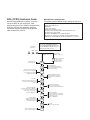
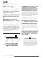
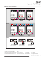
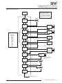
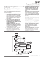
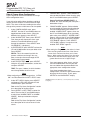
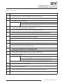
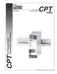
SPA2 (TPRG) Quickstart Guide
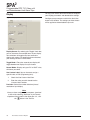
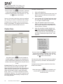
Default/Factory Configuration
The following are the default factory settings for your unit.
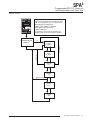
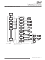
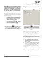
Use the front pushbuttons to quickly and easily
set-up the SPA2 for your application. After
programming your alarm using the diagram below,
install the unit into your application using the
connection diagrams and terminal designation
table located in this manual.
Front Panel
Pushbuttons
UP
DOWN
Input 4W RTD, 0-100°C
Display Normal Mode, PV
60Hz Filter
Broken wire enabled
Running Average Filter set to 4
All alarms set to Trip High at 50°C with Deadband set to 0
All alarms range set to 0-100
All alarms have OOR & Sensor Failure disabled
All alarms are configured as Fail Safe, latching disabled, 0 delay
AO(if fitted) : Current 4-20mA, fail high, hold duration of 1 second
Use the UP and DOWN pushbuttons
to scroll through menus and sub-menus.
Use the SELECT pushbutton to access
menus and/or make a choice.
SELECT
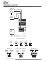
Security Jumper
installed in OFF position.
Security Jumper
installed in ON position.
ENTER
PASS
Configure Sensor:
Choose input type.
CONFG
SENSR
Enter the password
code to enable
settings changes.
(Default = 55)
D
U
CONFG
OPTNS
D
Scale Input "Smart Scaling":
Set the values to be displayed
at zero and full scale without
calibration equipment.
U
SCALE
INPUT
D
U
APPLY
INPUT
D
Trim Input:
Match the actual reading of your
SPA2 to a calibrated or known
value.
U
D
U
D
Configure Analog Output:
Select volt or current output.
Choose damping value and fail mode.
U
SCALE
AOUT
D
U
TRIM
AOUT
D
Configure Alarm:
Set trip point, dead band,
high/low trip, delay, and
latching/non-latching.
Apply Input (Bench Scaling):
Using calibration equipment,
capture the zero and full scale
values.
TRIM
INPUT
CONFG
AOUT
Scale Analog Output:
Connect the SPA2 into a calibration
set-up as shown in the manual
and scale the analog output.
(Requires -AO Option)
Configure Options:
Set engineering units, decimal
places, 50/60Hz filter, broken wire
detection and scaling.
U
Trim Analog Output:
Connect the SPA2 into a calibration
set-up as shown in the manual and
trim the analog output.
(Requires -AO Option)
CONFG
ALARM
D
U
CONFG
PASWD
D
U
Exit Configuration Menu:
Return to process display.
CONFG
EXIT
Password:
View or change password.
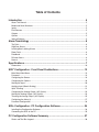
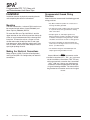
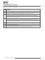
Table of Contents
Introduction.............................................................................................................................................. 5
About This Manual......................................................................................................................... 5
Model and Serial Numbers............................................................................................................ 5
Inputs............................................................................................................................................. 5
Dual Sensors................................................................................................................................. 5
Outputs.......................................................................................................................................... 5
Options.......................................................................................................................................... 5
Internal Settings............................................................................................................................. 5
Alarm Terminology.......................................................................................... 6
Trip Point........................................................................................................................................ 6
High/Low Alarms........................................................................................................................... 6
Latching/Non-Latching Alarms...................................................................................................... 6
Reset Point.................................................................................................................................... 6
Deadband...................................................................................................................................... 6
Failsafe Alarms.............................................................................................................................. 6
Normal .......................................................................................................................................... 6
Specifications.................................................................................................. 7
Dimensions.................................................................................................................................. 10
SPA2 Configuration: Front Panel Pushbuttons.......................................... 13
Main Menu/View Menu................................................................................................................ 13
Password..................................................................................................................................... 13
Configuring the Sensor................................................................................................................ 16
Configuring the Options............................................................................................................... 18
Scaling the Input.......................................................................................................................... 20
Applying Input (Bench Scaling)................................................................................................... 21
Input Trimming............................................................................................................................. 21
Configuring the Analog Output (-AO Option)............................................................................... 23
Scaling the Analog Output (-AO Option)...................................................................................... 24
Trimming the Analog Output (-AO Option)................................................................................... 25
Configuring the Alarm(s)............................................................................................................. 27
Password Configuration............................................................................................................... 34
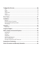
SPA2 Configuration: PC Configuration Software....................................... 34
Installing the Configuration Software........................................................................................... 34
Connecting the SPA2 to the PC................................................................................................... 35
PC Configuration Software Summary......................................................... 37
Status and Tool Bar Legend........................................................................................................ 38
Configuration Screens.................................................................................. 38
Input............................................................................................................................................. 38
Display......................................................................................................................................... 40
Alarms......................................................................................................................................... 41
Analog Output.............................................................................................................................. 44
Scaling......................................................................................................................................... 45
Custom Curve.............................................................................................................................. 46
Error Codes.................................................................................................... 47
Installation...................................................................................................... 48
Mounting...................................................................................................................................... 48
Making the Electrical Connections.............................................................................................. 48
Recommended Gound Wiring Practices...................................................................................... 48
CE Conformity............................................................................................................................. 49
Operation........................................................................................................ 48
Maintenance................................................................................................................................ 49
Customer Support......................................................................................... 49
SPA2 in Safety Instrumented Systems........................................................ 50
Fail Rate Data.............................................................................................................................. 50
Product Life.................................................................................................................................. 50
Installation................................................................................................................................... 50
Configuration............................................................................................................................... 50
Operation and Maintenance........................................................................................................ 51
Repair and Replacement............................................................................................................. 52
Recording and Reporting of SPA2 Performance.......................................................................... 52
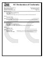
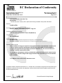
Declaration of Conformity............................................................................ 55
Return Procedures and Warranty Information............................................ 56
SPA2
Programmable RTD, T/C, Ohms, mV
and Potentiometer Limit Alarm Trips
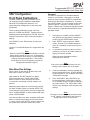
Introduction
Dual Sensors
This is the user’s manual for Moore Industries’ SPA2
(TPRG): Programmable RTD, T/C, Ohms, mV and
Potentiometer Limit Alarm Trips. The instrument
is configured using a combination of front panel
pushbuttons and a dedicated PC Configuration
Program. The SPA2 monitors a process variable and
provides up to four, fully user-configurable contact
closure outputs that can be individually programmed
to trip whenever the input falls outside a user-set, high
or low trip point. The SPA2 is typically used to activate
a warning light, bell or buzzer; or to initiate a system
shutdown. Thus, the instrument acts as a simple, but
highly reliable and effective means of monitioring and
safe-guarding a process.
The SPA2 (TPRG) has the capability of dual sensor
connections. This is beneficial when you choose to
use and view either a differential or averaging RTD
input and process variable. Refer to Table 4 for input
ranges and accuracies when using dual sensors.
About this Manual
2PRG
Wherever you see a “Note”, “Caution” or “WARNING”
pay particular attention.
WARNING - Hazardous procedure or condition that
could injure the operator.
Caution - Hazardous procedure or condition that
could damage or destroy the unit.
Note - Information that is helpful for a procedure,
condition, or operation of the unit.
Outputs
Alarms
The SPA2 can be ordered with two (-2PRG) or four
(-4PRG) contact closure alarms. Each alarm can be
individually programmed.
This is a two relay output with 5A@250Vac or 24Vdc,
50/60Hz non-inductive contact rating. The contact
arrangement is SPDT; however, the -2PRG output is
also available in a DPDT contact arrangement. All
relay contacts (NO, NC and COM) are available for
use. No jumpers are required.
4PRG
This is a four relay output with 5A@250Vac or 24Vdc,
50/60Hz non-inductive contact rating. The contact
arrangement is SPDT. All relay contacts (NO, NC and
COM) are available for use. No jumpers are required.
Model and Serial Numbers
Moore Industries uses a system of model and serial
numbers to keep track of all of the information on
every unit it sells and services. If a problem occurs
with your SPA2, check for a tag affixed to the unit
listing these numbers. Supply the Customer Support
representative with this information when calling.
Inputs
Refer to Table 4 of this manual for input ranges and
accuracies of the SPA2 (TPRG) (Temperature input
Programmable).
Options
Analog Output (-AO)
The SPA2 can be equipped with a scaleable analog
output option to provide a 0-20mA or 0-10V output.
-AO equipped units are set by the user to provide
either current (user-configurable between source or
sink) or voltage.
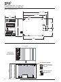
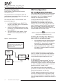
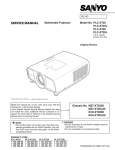
Internal Settings
The password security function of the SPA2 is
controlled by a single jumper inside the top of the
unit housing. You will need to remove the top cover
in order to access the jumper. Refer to Figure 2 for
location and jumper settings.
The Interface Solution Experts
5
SPA2
Programmable RTD, T/C, Ohms, mV
and Potentiometer Limit Alarm Trips
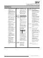
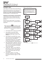
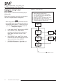
Alarm Terminology
Before setting up the SPA2, or incorporating the unit
in your application, Moore Industries suggests that
all users take a few moments to become familiar with
some of the terms associated with the use of process
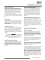
instrumentation alarms. The figure below illustrates
the way the SPA2 alarms operate.
The Trip Point is the process input level at which the
user wants an alarm relay to change state, typically
going into an alarm condition, or “tripping”. In the
SPA2, the user sets the trip point for each installed
relay.
High/Low Alarms; High Alarms trip when the
process input goes above the trip point. Low Alarms
trip when the process input drops below the trip point.
Each of the SPA2 outputs can be set by the user to
function independently as either high or low alarms.
Latching and Non-latching Alarms; once tripped, a
latching alarm remains in alarm until the input returns
to a non-alarm level AND is manually reset. Nonlatching alarms return to a non-alarm state whenever
the process input returns to the Reset Point. The
SPA2 relays can be set by the user to function as
either latching or non-latching.
How Alarms Work with the Process Input
The Reset Point is the process input level at which
the user wants an alarm relay to change state,
typically going from alarm to non-alarm. The reset
point is not necessarily the same as the trip point,
because most applications call for a buffer zone or
“Deadband” around the trip point to allow for minute
fluctuations in the process input. In the SPA2, the
reset point is determined by the deadband setting.
Latching SPA2 alarms will not “clear” unless the reset
point has been reached or passed AND the manual
reset contacts have been shorted.
The Deadband is the range in which an alarm
remains tripped even after the process input has
returned to or passed the trip point. Deadband is not
required. When it is not incorporated into an alarm
application, the trip point and reset point are the
same. The deadband of the SPA2 is set by the user.
Failsafe Alarms are de-energized when tripped,
energized when the process input is at a non-alarm
level. Non-failsafe Alarms are energized whenever
tripped, de-energized when the process input is at
a non-alarm level. The relays in the SPA2 can be
switched from failsafe to non-failsafe at any time by
the user.
Normal is the term used to describe the “shelf-state”
of relay contacts. The contacts of a Normally Open
relay are open (infinite resistance) when the relay is
not energized. The contacts of a Normally Closed
relay are open when the relay is energized (closed
when not energized).
IN ALARM
IN NON-ALARM
HIGH ALARM
TRIP POINT
DEADBAND
RESET
RESET
DEADBAND
LOW ALARM
TRIP POINT
TIME
6
The Interface Solution Experts
NOTE:
Sometimes a non-alarm input level is
referred to as being in a “normal” condition.
This practice is intentionally avoided in this
manual. Do not confuse the term “normal”,
as in Normally Open or Normally Closed, with
a non-alarm input condition. In this manual,
“normal” is an exclusive reference to the shelf
state or quiescent state of an alarm’s relay
contacts, whether open or closed.
SPA2
Programmable RTD, T/C, Ohms, mV
and Potentiometer Limit Alarm Trips
Specifications
Performance Input Accuracy and Alarm
Trip Repeatability: Refer
to Table 4
Reference Junction
Compensation Accuracy
(T/C inputs only): ±0.45°C
Stability: Refer to Table 1
Dead Band: User-set
within selected input range;
fully scaleable and set in
user-selected engineering
units
Input to Output Response
Time: 256msec typical
(Defined as the time from
step change on input to
alarm state change when
alarm is set to trip midpoint)
Alarm Trip Delay:
Programmable from 0-120
seconds
Power Supply Effect:
±0.002% of span for a 1%
change in line voltage
(AC or DC)
Isolation: 500Vrms
between case, input, output
(units with -AO option)
and power, continuous.
Dielectric Strength: Will
withstand a 1966Vdc
dielectric strength test
for two seconds(with no
breakdown)
Power Supply:
Universal 21.6-375Vdc or
90-260Vac; 24DC range,
18-30Vdc; UAC range,
90-260Vac; 110DC range,
75-150Vdc;
Performance Relay Outputs: Single(continued) pole/double-throw (SPDT), 1
form C, rated 5A@250Vac,
50/60Hz or 24Vdc, noninductive -DPDT option:
Double-pole/double-throw
(DPDT), 2 form C, rated
5A@250Vac, 50/60Hz or
24Vdc, noninductive
Performance
with Analog
Output (-AO
Option)
Power Consumption:
3W typical, 6W max.
Input Impedance:
T/C inputs, 40Mohms,
nominal
Input Over-Range
Protection: ±5Vdc
Excitation Current: (RTD
and Ohms) 250 microamps,
±10%
WITH ANALOG OUTPUT
Output Accuracy: Current,
±0.01% of max. span
(±2 microamps); Voltage,
±0.01% of max. span
(±1mV)
Response Time: 256msec
maximum
(128msec typical) for the
output to change from 10%
to 90% of its scale for an
input step change of 0 to
100%
Ripple (up to 120Hz):
Current output, 10mVp-p
when measured across a
250ohm resistor; Voltage
output, 50mVp-p max.
Output Limiting:
Current outputs,
Output
0-20mA
4-20mA
X-20mA
(0<X<4)
Failure Limits
0, 23.6mA
3.6, 23.6mA
(90% of X), 23.6mA
Voltage output, -0.5-11V
Load Capability: Source
mode (internal power
supply), 0-1000 ohms for
current output; greater then
or equal to to 2000 ohms
resistance on current output
Load Effect (current
outputs): ±0.01% of
span from 0 to 1000 ohms
resistance on current output
Ambient Operating Range:
Conditions -40°C to +85°C
(-40°F to +185°F)
Storage Range:
-40°C to +85°C
(-40°F to +185°F)
Ambient Ambient Temperature Effect:
Conditions Refer to Table 3
(continued) Effect of Ambient
Temperature on Reference
Junction Compensation
(T/C inputs only): ±0.005°C
per °C change of ambient
temperature
Relative Humidity:
0-95% non-condensing
RFI/EMI Protection:
With Universal Power Supply
or -RF Option: 80% AM at
1Khz 20V/m @ 20-1000Mhz
per IEC61000-4-3
All other units: 80% AM at
1Khz 10V/m @ 20-1000Mhz
per IEC61000-4-3.
Noise Rejection: Common
Mode, 100dB@50/60Hz
Normal Mode, refer to Table 2
Adjustments Front panel pushbuttons
parameter configurations;
Internal jumper and menu
password protect parameter
settings
Indicators LCD: 2x5 14-segment
characters, backlit,
alphanumeric readout
accurate to the nearest digit.
Range: -99999 to 99999;
Decimal point can be user-set
LED Type: INPUT LED: Dual
color LED indicates input
failure
READY LED: Green LED
indicates unit is operating
properly
ALARM 1, 2, 3 and 4 LED:
Dual color LED per relay
indicates alarm status
Display Accuracy:
±1 digit; when scaling the
display (or in custom mode),
high input-to-display span
ratios decrease display
accuracy
Weight 544 g to 601 g
(19.2 oz to 21.2 oz)
Specifications and information subject to change without notice.
The Interface Solution Experts
7
SPA2
Programmable RTD, T/C, Ohms, mV
and Potentiometer Limit Alarm Trips
Table 1. Long-Term Stability
Input-to-Relay
(Years)
Input-to-Output (Years)
Stability
(% of maximum
span)
1
3
5
1
RTD, Ohm, & Pot Inputs
0.09
0.16
0.21
0.047
0.081 0.104
T/C & mV Inputs
0.08
0.14
0.18
0.008
0.014 0.019
3
Table 2. Normal Mode Rejection Ratio
Max. p-p Voltage Injection for
100dB at 50/60Hz
T/C: J, K, N, C, E
150mV
T/C: T, R, S, B
80mV
Pt RTD: 100, 200, 300ohms
250mV
Pt RTD: 400, 500, 1000ohms
1V
Ni: 120ohms
500mV
Cu: 9.03ohms
100mV
Sensor Type
Resistance
1-4kohms
0.25-1kohms
0.125-0.25kohms
mV
250-1000
62.5-250
31.25-62.5
1V
250mV
100mV
Table 3. Ambient Temperature Effect
Accuracy per 1°C (1.8°F) change in Ambient
*RTD
0.0035°C
Millivolt
0.5microvolts + 0.005% of reading
Ohm
0.002ohms + 0.005% of reading
Thermocouple
Accuracy per 1°C (1.8°F) change in Ambient
0.00016°C + 0.005% of reading
J
K
0.0002°C + 0.005% of reading
E
0.00026°C + 0.005% of reading
T
0.0001°C + 0.005% of reading
R, S
0.00075°C + 0.005% of reading
B
0.0038°C + 0.005% of reading
N
0.0003°C + 0.005% of reading
C
0.00043°C + 0.005% of reading
mV
0.5microvolts + 0.005% of reading
*Accuracy of Ni672 is 0.002°C
8
The Interface Solution Experts
5
SPA2
Programmable RTD, T/C, Ohms, mV
and Potentiometer Limit Alarm Trips
Table 4. Accuracy with RTD, Thermocouple, Ohms, Potentiometer, Millivolt Inputs and Four Terminal Dual/Triple Ranges
Input
Type
α
Ohms
RTD
(2-, 3-,
4-Wire)
100
Dual
(2-Wire,
One 2-Wire
and
One 3-Wire)
400
Maximum
Range
500
-240 to 960°C
(-400 to 1760°F)
-200 to 850°C
(-328 to 1562°F)
1000
0.003850
Dual 500
Dual 1000
Triple 1000
Platinum
100
200
400
500
0.003902
-200 to 260°C
(-328 to 500°F)
-200 to 440°C
(-328 to 824°F)
Triple 500
Triple 1000
-200 to 80°C
(-328 to 176°F)
-150 to 720°C
(-238 to 1328°F)
-100 to 260°C
(-148 to 500°F)
-100 to 440°C
(-148 to 824°F)
-100 to 80°C
(-148 to 176°F)
-200 to 510°C
(-328 to 950°F)
-80 to 320°C
(-112 to 608°F)
-100 to 260°C
(-148 to 500°F)
-100 to 440°C
(-148 to 824°F)
-100 to 80°C
(-148 to 176°F)
-240 to 580°C
(-400 to 1076°F)
-100 to 360°C
(-148 to 680°F)
Nickel
0.00672
120
Copper
0.00427
9.035
-50 to 250°C
(-58 to 482°F)
Potentiometer
-200 to 440°C
(-328 to 824°F)
-200 to 80°C
(-328 to 176°F)
-100 to 650°C
(-148 to 1202°F)
100
n/a
-200 to 260°C
(-328 to 500°F)
10°C
(18°F)
0.003916
Direct Resistance
±0.1°C
(±0.18°F)
1000
Dual 500
Dual 1000
mV
Input Accuracy/
Repeatability
300
Triple 500
T/C
Minimum
Span
200
Triple
(2-Wire)
Ohms
Conformance
Range
±0.85°C
(±1.53°F)
-65 to 280°C
(-85 to 536°F)
0-4095ohms
0-2000ohms
0-4000
0-4000ohms
Dual 0-2000ohms
0-2000ohms
10ohms
±0.4ohms
Triple 0-1300ohms
4000 max.
0-1300ohms
0-100%
-180 to 760°C
(-292 to 1400°F)
-150 to 1370°C
(-238 to 2498°F)
-170 to 1000°C
(-274 to 1832°F)
-170 to 400°C
(-274 to 752°F)
0 to 1760°C
(32 to 3200°F)
0 to 1760°C
(32 to 3200°F)
400 to 1820°C
(752 to 3308°F)
-130 to 1300°C
(-202 to 2372°F)
0 to 2300°C
(32 to 4172°F)
10%
35°C
(63°F)
40°C
(72°F)
35°C
(63°F)
35°C
(63°F)
50°C
(90°F)
50°C
(90°F)
75°C
(135°F)
45°C
(81°F)
100°C
(180°F)
±0.1%
±0.25°C
(±0.45°F)
±0.3°C
(±0.54°F)
±0.2°C
(±0.36°F)
±0.25°C
(±0.45°F)
±0.55°C
(±0.99°F)
±0.55°C
(±0.99°F)
±0.75°C
(±1.35°F)
±0.4°C
(±0.72°F)
±0.8°C
(±1.44°F)
n/a
4mV
±30microvolts
J
n/a
n/a
K
n/a
n/a
E
n/a
n/a
T
n/a
n/a
R
n/a
n/a
S
n/a
n/a
B
n/a
n/a
N
n/a
n/a
C
n/a
n/a
DC
n/a
n/a
0-1300ohms
0-100%
-210 to 770°C
(-346 to 1418°F)
-270 to 1390°C
(-454 to 2534°F)
-270 to 1013°C
(-454 to 1855.4°F)
-270 to 407°C
(-454 to 764.6°F)
-50 to 1786°C
(-58 to 3246.8°F)
-50 to 1786°C
(-58 to 3246.8°F)
200 to 1836°C
(392 to 3336.8°F)
-270 to 1316°C
(-454 to 2400.8°F)
0 to 2338°C
(32 to 4240.4°F)
-50 to 1000mV
The Interface Solution Experts
9
SPA2
Programmable RTD, T/C, Ohms, mV
and Potentiometer Limit Alarm Trips
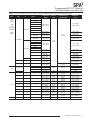
Figure 1. SPA2 (TPRG) Dimensions
REF.
136mm
(5.35 in)
REF. 131mm
(5.17 in)
118mm
(4.6 in)
55mm
(2.1 in)
READY INPUT
TRIP 1
TRIP 2 TRIP 3 TRIP 4
52mm
(2.06 in)
UP
COM
100mm
(3.9 in)
DOWN SELECT
CL
SPA2
REF. 47mm
(1.87 in)
SITE
PROGRAMMABLE
ALARM
123mm
(4.8 in)
Figure 2. Setting the Internal Jumper for Password Security ON or OFF
SPA2 TOPSIDE
1
2
3
3
4
4
INPUT
2
INPUT
MR
MR
REMOVE PANEL
BY UNSCREWING
TOP FOUR SCREWS
1
+lo Source
+Io Source
-Io Source
+Io Sink
+Vo
+Vo
A OUT
-lo Source
+lo Sink
-Vo
-Io Sink
-Vo
-lo Sink
SET PASSWORD SECURITY
10
The Interface Solution Experts
BACK
FRONT
PASSWORD SECURITY
IS OFF. NO PASSWORD
REQUIRED.
PASSWORD SECURITY
IS ON. PASSWORD
REQUIRED.
SPA2
Programmable RTD, T/C, Ohms, mV
and Potentiometer Limit Alarm Trips
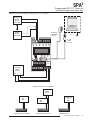
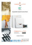
Figure 3. SPA2 (TPRG) Terminal Designations
1 2 3 4
+Vo
-Vo
-Io Sink
NC4
RELAY 4
GND
ACC/DCC
NOT
USED
AC/DC
NC2
CM2
NO2
CM1
NC1
NO1
GND
ACC/DCC
NOT
USED
AC/DC
NC2
CM2
NO2
CM1
NC1
NO1
GND
ACC/DCC
AC/DC
NC2
NOT
USED
CM2
NO2
NC1
CM1
NO1
RELAY 1
2PRG -DPDT -AO
CM4
NO4
NC3
CM3
NO3
NC2
CM2
NO2
NC1
CM1
NO1
N/A
N/A
N/A
N/A
N/A
N/A
RELAY 3
-Io Source
+Io Sink
MR
MR
+Vo
-Vo
-Io Sink
-Io Source
+Io Sink
+Io
Source
MR
MR
+Vo
-Vo
-Io Sink
-Io Source
+Io Sink
MR
MR
+Io
Source
GND
ACC/DCC
1 2 3 4
RELAY 1
2PRG -AO
OUTPUT
INPUT
RELAY 2
RELAY 2
NOT
USED
1 2 3 4
AC/DC
1 2 3 4
NC4
RELAY 2
4PRG
OUTPUT
INPUT
NC2
RELAY 1
CM2
NO2
NC1
CM1
NO1
GND
ACC/DCC
AC/DC
NOT
USED
NC2
CM2
OUTPUT
CM4
RELAY 4
2PRG -DPDT
INPUT
RELAY 1
NO4
NC3
RELAY 3
RELAY 1
2PRG
WITH -AO
OPTION
NO2
NC1
CM1
NO1
GND
ACC/DCC
AC/DC
NC2
NOT
USED
CM2
NO2
NC1
CM1
NO1
RELAY 2
CM3
NO3
NC2
CM2
NO2
NC1
CM1
NO1
N/A
N/A
N/A
N/A
N/A
N/A
RELAY 2
RELAY 1
MR
MR
1 2 3 4
+Io
Source
1 2 3 4
MR
MR
INPUT
MR
INPUT
MR
INPUT
RELAY 2
4PRG -AO
-AO OPTION
OUTPUTS
A OUT
A OUT
+Vo
DCS
or
PLC
Voltage Signal
Output from SPA2
4-20mA Output Loop
Voltage sourced by SPA2
KEY:
AC or DC = Power Input
ACC or DCC = Power Input
CM = Relay Common
DPDT = Double-Pole/Double-Throw
GND = Ground
-Vo
-Io Sink
4
3
2
1
+Vo
-
-Io Source
+Io Sink
MR
+Io Source
INPUT
-Vo
-Io Sink
+
-Io Source
+Io Sink
DCS
or
PLC
+Io Source
MR
4
NOTES:
1. Terminal blocks can accommodate 14-22 AWG solid
wiring.
2. ±Io/±Vo labeling is present only when the unit is equipped
with the Analog Output (-AO) option.
3. Your input power requirement (AC or DC / ACC or DCC)
will depend upon your unit’s power need.
3
4-20mA Output Loop
Voltage sourced by DCS
2
GROUND
INPUT
1
+Vo
DCS +V
or
PLC
A OUT
-Vo
-Io Sink
4
3
2
1
-Io Source
+Io Sink
MR
+Io Source
INPUT
Io = Current Output
MR = Manual Reset
NO = Normally Open
NC = Normally Closed
Sink = Current Sink
Source = Current Source
SPDT = Single-Pole/Double-Throw
Vo = Voltage Output
The Interface Solution Experts
11
SPA2
Programmable RTD, T/C, Ohms, mV
and Potentiometer Limit Alarm Trips
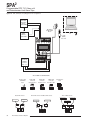
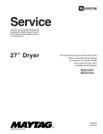
Figure 4. SPA2 (TPRG) Hook-Up Diagram For Front Panel Configuration and Sensor Hook-Up Guide
MILLIVOLT _
SOURCE
OR T/C +
SIMULATOR
OHMS
OR RTD
SIMULATOR
READY INPUT
TRIP 1
COM
TRIP 2 TRIP 3 TRIP 4
UP
DOWN SELECT
SPA2
SITE
PROGRAMMABLE
ALARM
AC OR DC
POWER
SUPPLY
-
GND
+
INPUT HOOK-UP CONNECTIONS
Thermocouple
and Millivolt
Input
+
2-Wire RTD
or Decade
Resistance Box
3-Wire RTD
or Decade
Resistance Box
4-Wire RTD
or Decade
Resistance Box
Potentiometer
Input
1 2 3 4
1 2 3 4
1 2 3 4
1 234
–
1 2 3 4
Dual 2-Wire Sensor
One 2-Wire Sensor and One 3-Wire Sensor
Three 2-Wire Sensors
Measurement 3
Measurement 2
Measurement 1
1 2 3 4
12
The Interface Solution Experts
Measurement 2
Measurement 1
1 2 3 4
Measurement 1
Measurement 2
1 2 3 4
SPA2
Programmable RTD, T/C, Ohms, mV
and Potentiometer Limit Alarm Trips
SPA2 Configuration:
Front Panel Pushbuttons
The SPA2 (TPRG) operating parameters may be
set using front panel pushbuttons and/or Moore
Industries’ PC Configuration Software. This
section describes configuration via the front panel
pushbuttons.
There are three pushbuttons on the unit’s front
panel; UP, DOWN and SELECT. Together with the
prompting messages displayed on the LCD, these are
used to access menus, and to view and change the
settings.
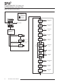
Password
This menu is bypassed if the Password Security
Jumper is not installed. If the jumper is installed,
the menu comes up when SELECT is pressed from
the display of the process variable input. To access
the security jumpers, you must remove the top cover
(refer to Figure 2). The menu is shown as part of
Figure 5. Refer to the Password Configuration section
of this manual for a more detailed description of the
password feature.
1.
Use SELECT as your “Enter” button, to make your
selections.
2.Press SELECT again to enter the “PASS”
screen. Use the UP and DOWN buttons to
enter “55”, the default screen for this point in
the menu.
Use the UP and DOWN buttons to navigate within the
menus.
Note:
Refer to the SPA2TPRG QuickStart Guide to see the
default factory settings for your unit. All parameters,
except the Custom Curve feature, can be configured
using the front panel pushbuttons. The Custom
Curve table can only be configured using the PC
Configuration Software Program.
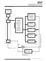
Figure 5 gives an overview of the Main menu; the
View menu is shown in Figure 6.
Upon power-up, the SPA2 defaults to a display
of the measured value. Pressing the DOWN
button accesses a series of displays that show,
in succession, the settings currently stored in unit
memory.
Once the Main Menu has been accessed, the DOWN
button is used to move through all of the sub-menus
in a loop. Pressing the SELECT button accesses the
first screen of the sub-menu shown on the LCD.
3.
If a password has been set (four characters,
maximum), use the UP or DOWN buttons to
display the correct password.
When the correct password number is
displayed, press SELECT.
Note:
If the correct password is not known, the unit
settings can be viewed, but not changed.
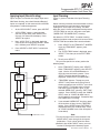
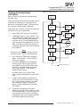
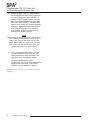
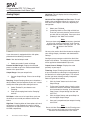
Main Menu/View Settings
Depending upon whether or not the Security Jumper
has been installed (Figure 2), pressing SELECT will
access either the first screen in the main configuration
menu, “CONFG SENSR”, or the password code query
screen, “ENTER PASS”.
If the jumper is installed, pressing SELECT
from the display of the process variable input
will bring up the “ENTER PASS” screen.
4.
If you have entered the correct password, the
sensor configuration menu, “CONFG SENSR”,
will be accessed. If not, the display will show a
“VIEW ONLY” message.
5.
From “VIEW ONLY”, press SELECT to go
back to the process variable input. Use the
UP and DOWN buttons to view the settings in
the various menus. The “VIEW ONLY” mode
locks out any attempt to make changes to the
settings.
Note:
The menu to set or change the password stored
in SPA2 memory is presented in the Password
Configuration section of the manual.
The Interface Solution Experts
13
SPA2
Programmable RTD, T/C, Ohms, mV
and Potentiometer Limit Alarm Trips
Figure 5. Main Menu and Password Menu
U = UP Key
D = DOWN Key
SEL = SELECT Key
U = No action
D = No action
PW = Password
READY INPUT
TRIP 1
UP
COM
U
CONFG
SENSR
TRIP 2 TRIP 3 TRIP 4
DOWN SELECT
U/D
SEL
CONFG SENSR
menu
D
VIEW MENU
U
SPA2
CONFG
OPTNS
SITE
PROGRAMMABLE
ALARM
SEL
D
CONFG OPTNS
menu
U
SCALE
INPUT
PROCESS VALUE
DISPLAY
SEL
SCALE INPUT
menu
SEL
APPLY INPUT
menu
SEL
TRIM INPUT
menu
SEL
CONFG AOUT
menu
D
U
If PW jumper fitted
If no PW jumper
ENTER
PASS
APPLY
INPUT
U/D
D
SEL
U
0
PASS
SEL (if correct PW)
SEL
TRIM
INPUT
U = Inc. count
D
D = Dec. count
SEL (if incorrect PW)
VIEW
ONLY
U/D
If no
-AO option
SEL
U
CONFG
AOUT
D
U
D
U
TRIM
AOUT
SEL
If no
-AO option
SCALE
AOUT
SCALE AOUT
menu
SEL
TRIM AOUT
menu
SEL
CONFG ALARM
menu
D
U
CONFG
ALARM
D
U
CONFG
PASWD
SEL
D
PASSWORD
menu
U
CONFG
EXIT
D
SEL
14
The Interface Solution Experts
SEL
CONFG EXIT
menu
SPA2
Programmable RTD, T/C, Ohms, mV
and Potentiometer Limit Alarm Trips
Figure 6. View Menu
COM
TRIP 1
TRIP 2 TRIP 3 TRIP 4
UP
DOWN SELECT
SPA2
SITE
PROGRAMMABLE
ALARM
PROCESS VALUE
DISPLAY
*If set as a:
• TRIP alarm, trip point value is displayed along
with an "H" (high alarm) or an "L" (low alarm),
depending upon configuration
• FAULT alarm, "FAULT" is displayed
• ROC (Rate of Change) alarm,
"ROC" is displayed
• If no button is pressed for 10 seconds, the
display returns to the Process Value reading
U/D
U
XXXXX
ZERO
(IF AOUT)
D
If no AOUT
READY INPUT
U
If no AOUT
XXXXX
FULL
(IF AOUT)
D
U
U
*XXXXX
AL1
D
U
*XXXXX
AL2
If 2 alarms
D
U
*XXXXX
AL3
D
U
*XXXXX
AL4
D
The Interface Solution Experts
15
SPA2
Programmable RTD, T/C, Ohms, mV
and Potentiometer Limit Alarm Trips
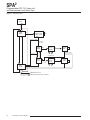
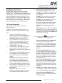
Configuring the Sensor
5.
If you selected an RTD or T/C input, use the
UP and DOWN buttons to select the unit you
wish displayed; press SELECT. The next
menu is “EXIT SENSR”.
If the Password Jumper is not installed, the password
sub-menu is bypassed, and the “CONFG SENSR”
menu is accessed by pressing SELECT from the
process variable display.
If selecting a mV, Resistance (single sensor)
or Potentiometer input, the next menu is “EXIT
SENSR”.
If a Resistance range was selected as your
input, and you are using dual sensors, you will
need to choose whether you want to view your
process variable in an average (PV AVG) or
differential (PV DIFF) display; press SELECT.
6.
“EXIT SENSR” appears. If all values in this
parameter have been set, press SELECT. If
not, return to the menu and set your values.
7.
The next display is the menu for the selection
of functional options, ”CONFG OPTNS”. To
skip the rest of the configuration menus and
return to the process variable display, press the
UP button twice (to “CONFG EXIT”), and press
SELECT.
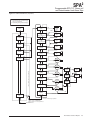
Figure 7 gives an overview of the Sensor
Configuration menu.
1.
From the “CONFG SENSR” display, press
SELECT.
2.
At “SENSR TYPE” press SELECT. Use the
UP or DOWN arrow buttons to scroll through
the options in the “Sensor Selection List” box
shown in Figure 7, for input type. The default
display for this menu is always the last setting.
3.
When the display shows the type of input that
you choose to use, press SELECT.
4.
Next, the available input values are displayed.
Use the UP or DOWN buttons to scroll through
the selections, choose a value that is greater
than or equal to the maximum value for the
input you will be monitoring and press SELECT
when the value has been displayed.
16
The Interface Solution Experts
SPA2
Programmable RTD, T/C, Ohms, mV
and Potentiometer Limit Alarm Trips
Figure 7. CONFG SENSR Menu
Use the UP and
Down buttons
to cycle through
the lists
RTD Type List:
"P3850 R100, R200, R300,
R400, R500, R1000"
"P3902 R100, R200,
R400, R500, R1000"
"P3916 R100"
"NI672 R120"
"CU427 R9035"
CONFG
SENSR
SEL
Sensor Selection List
U
SENSR
TYPE
SEL
D
U/D
"RTD 2WIRE"
"RTD 3WIRE"
"RTD 4WIRE"
"MV"
"OHMS 2WIRE"
"OHMS 3WIRE"
"OHMS 4WIRE"
"T/C"
"T/C+RJC"
"POT"
"RTD 2X2W"
"RTD 2X3W"
"OHMS 2X2W"
"OHMS 2X3W"
"RTD 3X2W"
"OHMS 3X2W"
MV Range List:
"1000, 500, 250,
125, 62.5, 31.25"
T/C Type List:
"J, K, E, T, R,
S, B, N, C"
SEL
SEL (if Dual Sensor)
Resistance Range List:
"4000, 2000, 1000,
500, 250, 125"
U
EXIT
SENSR
Potentiometer Range List:
"4000, 2000, 1000,
500, 250, 125"
D
SEL
SEL
SEL
CONFG OPTNS menu
SEL
TOGGLE
PV AVG/
PV DIFF
Temperature Selection List:
"DEG C", "DEG F",
"KELVN", "DEG R"
SEL
SEL (if Dual Sensor)
The Interface Solution Experts
17
SPA2
Programmable RTD, T/C, Ohms, mV
and Potentiometer Limit Alarm Trips
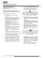
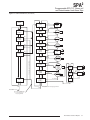
Configuring the Options
6.
Figure 8 gives an overview of the Options
Configuration menu.
You may configure the process variable display,
decimal places, 50/60Hz/FAST* filter selection, broken
wire detection and the scaling mode from this menu.
Note:
A faster respond time can be achieved when
selecting the Fast option, but this will also produce
a reduced accuracy and increase the possibility of
mains-induced noise. * FAST option available only
for units with software V2.11 or greater.
To configure the options of the the SPA2:
1.
At the “CONFG OPTNS” screen, press
SELECT.
2.
“DSPLY MODE” appears. Press SELECT to
enter the menu. Choose between “NORM
MODE” and “TOGLE MODE” by using the UP
and DOWN buttons. Press SELECT.
NORM MODE– Displays only your PV or
AOUT value, whichever you select.
TOGLE MODE– Every four seconds your
display will toggle between two displays that
you choose.
3.
Next, “DSPLY SRC 1” appears. Press SELECT
and choose between “AOUT” (if your unit is
equipped with the -AO option), “RJC” or “PV”
by using the UP and DOWN buttons. Press
SELECT.
If you selected “TOGLE MODE”, you will next
be asked to enter your “DSPLY SRC 2” value.
4.
The “DSPLY EGU 1” prompt is brought up.
Press SELECT and choose the desired
appearance of your display. Press SELECT.
If you selected “TOGLE MODE”, you will next
be asked to enter your “DSPLY EGU 2” value.
5.
Next, the “SET DPS” display appears. Press
SELECT. Scroll through the available choices
by using the UP and DOWN buttons and press
SELECT once you have made your selection.
18
The Interface Solution Experts
“SET FILTR” appears; press SELECT. Here,
you must select the proper line frequency of
your AC source–50Hz or 60Hz or you can
choose the FAST* option; press SELECT.
7.
When “SET BWIRE” appears, press SELECT
to enter the menu. You must choose whether
or not to enable Broken Wire Detection. Press
SELECT.
Broken Wire Detection– The SPA2 monitors
your process variable. If the monitored value
falls equal to or below a set value, then a state
of Broken Wire is declared.
8.
“SCALE MODE” appears; press SELECT.
Choose whether or not to enable scaling. This
will be configured in the next menu. Select
“SCALE OFF” or “SCALE ON” and press
SELECT.
Caution:
Turning on scaling will disable custom-curve and
turning off scaling will not restore custom-curve. The
custom-curve can only be restored using the PC
configuration Software. The custom data points will
remain unchanged.
Scale Mode– This allows you to customize
your display for your application. By example:
if your process is sending a 32°-212° reading
to the SPA2 and you wish to view the input as
0-100% then this can be accomplished with
the Scale Mode feature.
9.
“EXIT OPTNS” appears. Press SELECT.
Proceed to the “SCALE INPUT” menu.
SPA2
Programmable RTD, T/C, Ohms, mV
and Potentiometer Limit Alarm Trips
Figure 8. CONFG OPTNS Menu
**When FROM PC is selected,
the actual text is input from the
PC Configuration Program.
The display shows the PC default
("*****") until the proper EGU is
downloaded from the PC program.
CONFG
OPTNS
SEL
U
DSPLY
MODE
SEL
TOGGLE
*NORM/
TOGLE
D
U
DSPLY
SRC1
SEL
SEL
D
PV
AOUT
RJC
U
PV
AOUT
RJC
U
D
SEL
EGU SELECTION LIST
AUTO MODE
**FROM PC
DEG C
DEG F
KELVN
DEG R
MA
MV
OHMS
PCT
PSI
PSIG
VOLTS
*DSPLY SRC2 and DSPLY EGU2
are skipped if display is in Normal Mode.
U
*DSPLY
SRC2
SEL
D
D
SEL
U
DSPLY
EGU1
SEE EGU
SELECTION
LIST
SEL
D
SEL
U
*DSPLY
EGU2
SEL
SEE EGU
SELECTION
LIST
D
SEL
U
SET
DPS
SEL
D
SEL
U
SET
FILTR
60 HZ
50 HZ
FAST*
SEL
D
U
SEL
SET
BWIRE
AUTO
XXXXX
XXXX.X
XXX.XX
XX.XXX
U
D
U
D
* FAST option available
only for units with V2.11
or greater
TOGGLE
BWIRE
ON/OFF
D
U
SCALE
MODE
SEL if BWIRE OFF
SEL
TOGGLE
D
SCALE
ON/OFF
U
EXIT
OPTNS
SEL
D
SEL
SCALE INPUT menu
The Interface Solution Experts
19
SPA2
Programmable RTD, T/C, Ohms, mV
and Potentiometer Limit Alarm Trips
Scaling the Input
Figure 9. SCALE INPUT Menu
Scaling allows you to take your PV (Process Variable)
reading and manipulate it to a more customized
display range. PV is the unit read after selecting your
input type. For example, choosing a Resistance input
would then produce a PV displayed in ohms.
NOTES:
1. When scaling the input, the value
displayed represents the actual input.
2. When the SCALE INPUT menu is
accessed, the APPLY INPUT menu is
skipped and the TRIM INPUT menu
appears.
Figure 9 gives an overview of the Input Scaling menu.
Also known as “Smart Ranging”, scaling of the SPA2
(TPRG) allows the user to set the zero and full scale
values of the input from the intended application,
without having to connect the unit to any calibration
equipment.
SCALE
INPUT
SEL
U
Continue with the “SCALE INPUT” if you enabled
scaling in the previous menu. To proceed, follow the
steps below.
INPUT
ZERO
3.Press SELECT at the “INPUT FULL” screen.
Enter the value you wish displayed when your
input is at full scale. Press SELECT.
If you selected “SCALE OFF” in the “CONFG
OPTNS” menu, the menu skips to Step 6. If
you selected “SCALE ON”, proceed to Step 4.
4.
Next, “SCALE ZERO” is displayed. Use the UP
and DOWN buttons to adjust your scaled zero
value. This is the value that will be displayed
when you are at the zero end of your display
range. Press SELECT.
5.
“SCALE FULL” appears. Press SELECT to
enter the menu. Enter the value you wish as
your full scaled range– the value displayed
when you are at the full end of your range.
Press SELECT.
6. “EXIT SCALE” appears. If all scaling
parameters have been set, press SELECT.
The next menu selection to appear is “TRIM
INPUT”.
20
The Interface Solution Experts
INPUT
FULL
XXXXX
EGU
SEL
D
U
D
SEL
U
SCALE
ZERO
If Scale
Mode ON
SEL
XXXXX
EGU
D
U
SCALE
FULL
D
U
SEL
XXXXX
EGU
SEL
EXIT
SCALE
D
SEL
U
D
SEL
If Scale
Mode OFF
2. Press SELECT at the “INPUT ZERO”
parameter and enter the value you want
displayed when your input is at zero. Press
SELECT.
D
U
If Scale Mode OFF
At the “SCALE INPUT” display, press SELECT.
U
SEL
D
Note:
When using the front panel push buttons to enter
your scaling values, you may enter only whole
number increments. To adjust your value past the
decimal point, you must use the PC Configuration
Program.
1.
XXXXX
EGU
SEL
TRIM INPUT menu
U
D
SPA2
Programmable RTD, T/C, Ohms, mV
and Potentiometer Limit Alarm Trips
Applying Input (Bench Scaling)
Figure 10 gives an overview of the Apply Input menu.
With Bench Scaling, also called “Standard Ranging”,
inputs are “captured” at their zero and full scale levels
using external, calibrated equipment.
1.
At the “APPLY INPUT” screen, press SELECT.
2.
“APPLY ZERO” appears. Apply the input
you wish as your zero, press SELECT and
wait until it is flashed on the display. Press
SELECT to capture.
3.
Next, “APPLY FULL” is displayed. Apply the
value of your full range; press SELECT. When
this is flashed, press SELECT to capture.
4.Press SELECT at “EXIT APPLY” and exit the
menu.
Input Trimming
Figure 11 gives an overview of the Input Trimming
menu.
Sensor trimming increases the measurement accuracy
of the parameter you are trimming by matching the
reading of its actual input to its scaling. The SPA2
offers the use of a factory-configured trimming feature
(“FCTRY TRIM“) or user-set, one-point or two-point
(“USER 1PNT” OR “USER 2PNT”) trimming.
Unit default is “FCTRY TRIM”. If another trimming
selection had been made and you wish to return to the
“FCTRY TRIM” feature follow the instructions below.
1.Press SELECT at the “TRIM INPUT” SCREEN.
Once the “TRIM MODE” appears, press
SELECT.
2. The “FCTRY TRIM” feature is displayed, press
SELECT. This takes you to the “EXIT TRIM”
screen.
Figure 10. APPLY INPUT Menu
3.
To input user-specific trim values, perform the
following steps:
APPLY
INPUT
SEL
1.
At the “TRIM INPUT” display, press SELECT.
When “TRIM MODE” appears, press SELECT
again. Use the UP and DOWN buttons to
reach the user-set trimming menus. Press
SELECT once the desired parameter is
displayed– “USER 1PNT” or “USER 2PNT”.
2.
“TRIM ZERO” appears. To program, press
SELECT. Your present zero scaling value is
shown and prompts you to “APPLY” your value;
press SELECT. Once your value is present
and flashing, press SELECT again. If you
selected “USER 1PNT” trimming, “EXIT TRIM”
appears. Press SELECT to reach the “CONFG
AOUT” menu (or “CONFG ALARM” menu if
the -AO option is not enabled). Proceed to Step
3 for “USER 2PNT” trimming.
3.
If you selected “USER 2PNT” trimming, repeat
the instructions in Step 2 for the “TRIM FULL”
setting. Press SELECT when “EXIT TRIM” is
displayed to reach the “CONFG AOUT” menu
(or “CONFG ALARM” menu if the -AO option is
not enabled).
U
APPLY
ZERO
SEL
D
XXXXX
EGU
U
D
SEL
U
APPLY
FULL
D
SEL
XXXXX
EGU
U
D
SEL
U
EXIT
APPLY
D
SEL
To exit, press SELECT.
TRIM INPUT menu
Note:
Trim only the zero and full values entered in the
“SCALE INPUT” menu through the front panel
pushbuttons. To trim values other than those
specified in the “SCALE INPUT” menu, you must
use the PC Configuration Software program.
The Interface Solution Experts
21
SPA2
Programmable RTD, T/C, Ohms, mV
and Potentiometer Limit Alarm Trips
Figure 11. TRIM INPUT Menu
TRIM
INPUT
SEL
U
TRIM
MODE
SEL
FCTRY TRIM
USER 1 PNT
USER 2 PNT
D
U/D
SEL
If Factory Trim
If USER 1
or 2 PNT
TRIM
ZERO
XXXXX
APPLY
(ZERO)
SEL
XXXXX U/D
EGU
SEL
If USER 2PNT
U/D
If USER 1PNT
SEL
D
If USER 1PNT
U
If USER 2PNT
U
TRIM
FULL
U
SEL
D
D
CONFG AOUT menu
CONFG ALARM menu (If no AOUT)
22
The Interface Solution Experts
SEL
XXXXX
EGU
SEL
D
EXIT
TRIM
SEL
XXXXX
APPLY
FULL
U
U/D
SPA2
Programmable RTD, T/C, Ohms, mV
and Potentiometer Limit Alarm Trips
Configuring the Analog Output
(-AO Option)
4.Press SELECT at “FAIL MODE” to program
the setting. If choosing “FAIL HIGH”, “FAIL
LOW” or “HOLD LAST”, pressing SELECT
is your last step. This sends you to “EXIT
AOUT”.
If your unit is equipped with the -AO option, use this
menu for configuration.
HIGH/LOW– Choosing either of these options
will send the output to a High (23.6mA for
current; 11.0V for voltage) or Low (3.6mA for
current; -0.5V for voltage), respectively. This
can also be translated as 90% of the output’s
zero value.
Figure 12 gives an overview of the Analog Output
Configuration menu.
1.Press SELECT at the “CONFG AOUT” display.
This sends you to the “SEL AOUT” section.
Press SELECT and use the UP and DOWN
buttons to toggle between current and voltage.
When the selction you desire is displayed,
press SELECT.
2.
HOLD LAST– This will display the last value
present before the failure.
Once you reach the “SET DAMP” field, you
may skip the damping parameter, by using
the Down button to reach the next field. To set
damping, proceed to Step 3.
Choosing “HOLD GO-HI” or “HOLD GO-LO”
from the “FAIL MODE” screen and pressing
SELECT directs you to the “HOLD TIME”
portion of the menu. Press SELECT and use
the UP and DOWN buttons to enter a value
between 1 and 30 seconds; press SELECT.
This brings up “EXIT AOUT”. Pressing
SELECT displays the next menu option,
“SCALE AOUT”.
HOLD GO-HI/HOLD GO-LO– This will hold
the last value before failure, for a set time,
and then return to the High or Low value,
depending on configuration.
Damping– Output Damping allows you to
introduce a delay (0-30sec) into the response
of your unit in order to stop momentary input
variations from setting off alarms.
3.
To set damping, press SELECT at the “SET
DAMP” display. Use the UP and DOWN
buttons to enter a value between 0 and 30
seconds; press SELECT.
Figure 12. CONFG AOUT Menu
CONFG
AOUT
SEL
U
SEL
AOUT
TOGGLE
SEL
VOLT/
CURRENT
D
SEL
U
SET
DAMP
XX
SEC
(XX = 0-30)
SEL
D
U
D
SEL
U
FAIL
MODE
FAIL LOW
FAIL HIGH
HOLD GO-LO
HOLD GO-HI
HOLD LAST
SEL
D
U
If FAIL HIGH/FAIL LOW/
HOLD LAST
EXIT
AOUT
U/D
SEL
If HOLD GO-HI/GO-LO
D
U/D
HOLD
TIME
SEL
XX
SEC
(XX = 1-30)
U
D
SEL
SEL
SCALE AOUT menu
The Interface Solution Experts
23
SPA2
Programmable RTD, T/C, Ohms, mV
and Potentiometer Limit Alarm Trips
Scaling the Analog Output
(-AO Option)
Figure 13 gives an overview of the Analog Output
Scaling menu.
Follow these instructions to scale the analog output
after you have performed the configuration.
Note:
When using the front panel pushbuttons to enter
your scaling values, you may enter only values to
one decimal place (tenths). To adjust your value
past one decimal place, you must use the PC
Configuration Program.
1.
Figure 13. SCALE AOUT Menu
NOTES:
1. When setting zero and full values,
the values displayed are the analog output.
Zero and full in mA or Volts (depending upon
the output configuration).
2. Update your analog output during -AO scaling.
3. Rearranging values nulls your trim value.
4. Implement "auto increment" when incrementing
and decrementing zero and full counts.
SCALE
AOUT
SEL
At the “SCALE AOUT” display, press SELECT.
2. Press SELECT at the “AOUT ZERO”
parameter and enter the value you want to
output when your input is at zero. Press
SELECT.
U
AOUT
ZERO
D
XXXXX
MA/VOLT
SEL
AOUT
FULL
D
U
SEL
XXXXX
MA/VOLT
SEL
U
EXIT
SCALE
D
SEL
24
The Interface Solution Experts
D
U
3.Press SELECT at the “AOUT FULL” screen.
Enter the value you want to output when your
input is at full scale. Press SELECT.
4. “EXIT SCALE” appears. If all scaling
parameters have been set, press SELECT.
U
SEL
TRIM AOUT menu
D
SPA2
Programmable RTD, T/C, Ohms, mV
and Potentiometer Limit Alarm Trips
Trimming the Analog Output
(-AO Option)
Figure 14. TRIM AOUT Menu
TRIM
AOUT
Figure 14 gives an overview of the Analog Output
Trimming menu.
SEL
Output trimming increases the measurement accuracy
of the SPA2 by calibrating its analog output to the
device that is receiving the output. This ensures that
the instrument is being correctly interpreted.
U
TRIM
ZERO
Connect the unit as shown in Figure 15 and allow five
minutes for warm up and stabilization.
1.
At the “TRIM AOUT” display, press SELECT.
2.
“TRIM ZERO” appears. Press SELECT. The
value 0.000 (mA or V depending on the set up)
is shown. While monitoring your reading on
the meter, use the UP and DOWN buttons to
adjust the output to the desired level. Use the
meter in the set up to monitor the output as it
is adjusted. When the output is set as desired,
press SELECT.
SEL
D
XXXXX
MA/VOLT
U
D
SEL
U
TRIM
FULL
SEL
D
XXXXX
MA/VOLT
U
D
SEL
U
FCTRY
TRIM
SEL
D
TEST
AOUT
NO/
YES
SEL
U
Note:
The value on the LCD is the value that must be
trimmed in order to adjust to the desired level.
TOGGLE
SEL
XXXXX
MA/VOLT
D
U
D
SEL
U
3.Press SELECT at “TRIM FULL” and repeat
Step 2. Press SELECT. “FCTRY TRIM” is
shown on the display.
EXIT
TRIM
D
4. If you wish to disable the user-configured
trimming values and use factory trimming,
press SELECT at the “FCTRY TRIM” screen.
Use the UP and DOWN buttons to choose
“YES”; press SELECT. “TEST AOUT” is
brought up on the display.
By selecting “NO” at the “FCTRY TRIM”
screen, the user-configured trim values will be
used.
5.
In order to check output performance and
accuracy, you may want to perform an output
test. If you choose to enable this test, follow
the instructions in Step 6. To bypass this
feature, use the DOWN button and scroll to
“EXIT TRIM”.
6.
To enable the analog output test, press SELECT at the “TEST AOUT” display. Use the
UP and DOWN buttons to set your output test
value (this figure must fall within your sensor
configuration range value) and press SELECT.
“EXIT TRIM” appears; press SELECT.
SEL
CONFG ALARM menu
The Interface Solution Experts
25
SPA2
Programmable RTD, T/C, Ohms, mV
and Potentiometer Limit Alarm Trips
Figure 15. SPA2 (TPRG) Trimming Hook-Up Diagram For Front Panel Configuration
MILLIVOLT _
SOURCE
OR T/C +
SIMULATOR
OHMS
OR RTD
SIMULATOR
READY INPUT
TRIP 1
COM
TRIP 2 TRIP 3 TRIP 4
UP
DOWN SELECT
SPA2
SITE
PROGRAMMABLE
ALARM
AC OR DC
POWER
SUPPLY
GND –
+
HOOK-UPS FOR OUTPUT TRIMMING
EXTERNAL
POWER
SUPPLY
+ –
MULTIMETER
OR
DCS
+ –
CURRENT OUTPUT SOURCE
26
The Interface Solution Experts
MULTIMETER +
OR
DCS
–
CURRENT OUTPUT SINK
MULTIMETER
OR
DCS
+ –
VOLTAGE OUTPUT
SPA2
Programmable RTD, T/C, Ohms, mV
and Potentiometer Limit Alarm Trips
Configuring the Alarm(s)
SPA2 offers
The
you four alarms. Each of these
alarms may be configured as trip, fault or rate of
change alarms. The instructions below will explain the
steps to follow in order to set each type of alarm. This
section will be divided into three sub-sections: “Trip
Alarm Configuration”, “Fault Alarm Configuration” and
“Rate of Change Alarm Configuration”. Depending
upon the type of alarm you are setting, you may refer
to the section specific to your need at the time.
6.Pressing SELECT at the “SET HI/LO” menu
directs you to configure the alarm as an
“ALARM HI” or “ALARM LO”. Use the UP and
DOWN buttons to reach your selection and
press SELECT.
ALARM LO– You are notified if your process
input drops below your trip point setting.
ALARM HI– You are notified if your process
input exceeds your trip point setting.
7.
At the “SET LATCH” display, press SELECT
and choose “LATCH ON” or “LATCH OFF”
using the UP and DOWN buttons; press
SELECT.
Latching Alarm– When a SPA2 is configured
with latching alarms, an alarm condition will not
“clear” (the relay will not change state) until the
input returns to a non-alarm state AND manual
reset terminals are shorted.
Trip Alarm Configuration
Figure 16 gives an overview of the Trip Alarm
Configuration menu.
Trip alarms are used if the user desires an alarm
condition if a process value deviates from a set trip
point.
1.
At the “CONFG ALARM” menu, press
SELECT. Use the UP and DOWN buttons to
toggle between the four alarms. When the
desired alarm appears, press SELECT.
2.
At the “ALARM TYPE” menu press SELECT.
From here you will choose your alarm type.
Use the UP and DOWN buttons to scroll
through the selections. Press SELECT once
“ALARM TRIP” is displayed.
3.
At “ENTER TRIP”, press SELECT and enter
your alarm trip value. Use the UP and
DOWN buttons to select your trip value; press
SELECT.
Note:
If manual reset terminals remain shorted, this will
disable the alarm latching function.
8.Press SELECT at “SET FSAFE” to enter the
menu. Then use the UP and DOWN buttons
to switch from “ALARM FSAFE” to “ALARM
NONFS”. Make your selection and press
SELECT.
Fail Safe (ALARM FSAFE)– Will remain in
an alarm condition even if power to the unit is
removed. Its alarm trip relays are energized
whenever the process input is in a non-alarm
condition (including any dead band setting).
These relays de-energize when the process
input trips the alarm.
Non Fail Safe (ALARM NONFS)– With this
type of alarm relays are energized whenever
the process input is in an alarm condition.
These relays de-energize when the process
input returns to the reset point (including any
dead band).
4.Press SELECT at “ENTER DBAND” and enter
your dead band value if using dead band.
Press SELECT once your desired setting
appears.
Dead Band– The Dead Band is the range
within which an alarm relay remains in an
alarm condition even after the monitored
process variable input has returned to a safe
level, at or below/above the trip point setting.
5.Press SELECT at “ENTER DELAY” and input
your desired delay time by using the UP and
DOWN buttons.
Delay– When your unit is in an alarm
condition, the delay is the amount of time you
set (0-120sec) to elapse before a relay trip.
These manual reset terminals, labeled “MR”
are located on the top row of the SPA2.
9. “SENSR FAULT” appears. Select whether or
not to enable the sensor failure alarm by using
the UP and DOWN buttons; press SELECT.
Sensor Fault Alarm (SENSR FAULT)– If
enabled, this alarm will notify the user upon a
breakdown of input .
The Interface Solution Experts
27
SPA2
Programmable RTD, T/C, Ohms, mV
and Potentiometer Limit Alarm Trips
10. “RANGE ALARM” appears. Select whether
or not to enable the range alarm by using the
UP and DOWN buttons; press SELECT. If
enabled “LOWER POINT” appears, then use
the UP and DOWN buttons to set your lower
point value, press SELECT. “UPPER POINT”
appears, then use the UP and DOWN buttons
to set your upper point value, press SELECT.
“EXIT RANGE” appears. Press SELECT.
“EXIT ALRM*” appears. If range alarm not
enabled “EXIT ALRM*” appears.
Note:
When setting the Range Alarm, the values in Lower
Point must be greater than those of the Sensor
Lower Limit, and less than those set in Lower
Range. When setting the Upper Point, the value
must be less than the Sensor Upper Limit, and
greater than those set in Upper Range.
11. If you are to program other alarms, use the
UP and DOWN buttons to reach your next
alarm and follow the steps described in the
appropriate alarm configuration section.
If you have completed your alarm
configurations, use the UP and DOWN buttons
to bypass the alarm menu. To exit, press
SELECT at the “ALARM EXIT” display.
*ALARM X denotes the alarm (1, 2, 3 or 4) that you are currently
configuring.
28
The Interface Solution Experts
SPA2
Programmable RTD, T/C, Ohms, mV
and Potentiometer Limit Alarm Trips
Figure 16. CONFG ALARM Menu (Trip Alarm)
NOTES:
1. Smart Ranging skips standard ranging
and goes to dead band.
2. Input flashing during standard ranging.
ALARM
TYPE
CONFG
ALARM
D
SEL
ALARM
TRIP
FAULT
ROC
SEL
If TRIP
SEL
U
ENTER
TRIP
(Smart Ranging)
U
CONFG
ALARM1
SEL
U
SEL
CONFG
ALARM4
XXXXX
EGU
SEL
D
If
AL3
D
SEL
U
SEL
U
XXXXX
EGU
SEL
D
If
AL2
SEL
U
D
U
ENTER
DELAY
D
U
D
U
ENTER
DBAND
CONFG
ALARM3
U
SEL
INPUT
TRIP
(Standard Ranging)
D
U
XXXXX
EGU
SEL
D
D
CONFG
ALARM2
U/D
U
XXX
SEC
SEL
D
D
SEL
SEL
U
If
AL4
SET
HI/LO
D
TOGGLE
SEL
ALARM
HI/LO
D
SEL
U
SET
LATCH
TOGGLE
SEL
LATCH
ON/OFF
D
If more alarms are to be programmed
U
SET
FSAFE
FSAFE/
NONFS
XXXX
D
U
U/D
UPPER
POINT
U
SENSR
FAULT
U
SEL
SEL
TOGGLE
D
SEL
SEL
XXXX
U
D
D
SEL
U
D
TOGGLE
ON/OFF
EXIT
RANGE
U/D
U
RANGE ALARM
D
U
SEL
TOGGLE
EXIT
ALRM X*
D
SEL
SEL
ON/OFF
D
LOWER
POINT
D
SEL
U
ALARM
EXIT
U/D
SEL
D
U
U/D
U/D
IF ON SEL
SEL
IF OFF SEL
SEL
*The alarm channel being programmed
Proceed to ALARM EXIT if
no more alarms are to be programmed
SEL
PASSWORD menu
The Interface Solution Experts
29
SPA2
Programmable RTD, T/C, Ohms, mV
and Potentiometer Limit Alarm Trips
Fault Alarm Configuration
5.
Figure 17 gives an overview of the Fault Alarm
Configuration menu.
Fault alarms are set in order to notify you of any fault
conditions during your process. If you wish an alarm
condition when a malfunction occurs, use the Fault
Alarm.
Next, the “SPA FAULT” menu is displayed.
Press SELECT. Toggle between “ALARM
ON” and “ALARM OFF” by using the UP and
DOWN buttons and press SELECT when the
setting you desire is displayed.
6.Press SELECT at “ENTER DELAY” and enter
your desired delay time by using the UP and
DOWN buttons.
1.
At the “CONFG ALARM” menu, press
SELECT. Use the UP and DOWN buttons to
toggle between the four alarms. When the
desired alarm appears, press SELECT.
7.
At the “SET LATCH” display, press SELECT
and choose “LATCH ON” or “LATCH OFF”
using the UP and DOWN buttons; press
SELECT.
2.
At the “ALARM TYPE” menu press SELECT.
From here you will choose your alarm type.
Use the UP and DOWN buttons to scroll
through the selections. Press SELECT once
“ALARM FAULT” is displayed.
Refer to the “Trip Alarm Configuration” section
for a description of delay and latching alarms.
Below are the configuration options you are
given in setting up the fault alarm. You may
choose any combination of alarms including all
three.
SENSR FAULT– You are notified upon
breakdown of your input.
INPUT SAT– Should the input become
overloaded or saturated, your alarm would
activate.
SPA FAULT– Choosing this parameter
activates the alarm at any failure that occurs in
the SPA2 itself.
Note:
Enabling all fault alarm configurations will activate
the alarm at any failure that occurs
(refer to Table 7 in the Error Codes section
of this manual).
3.
“SENSR FAULT” appears. Press SELECT at
“SENSR FAULT”. Dependent upon whether
you wish the alarm activated due to a sensor
fault, use the UP and DOWN buttons to scroll
through the “ALARM ON” and “ALARM OFF”
options. Once you have made a selection,
press SELECT.
Sensor Fault Alarm (SENSR FAULT)– If
enabled, this alarm will notify the user upon a
breakdown of input .
4.Press SELECT at the “INPUT SAT” display.
You are given the choice of “ALARM ON” or
“ALARM OFF” by using the UP and DOWN
buttons. Choose your setting and press
SELECT.
30
The Interface Solution Experts
8.Press SELECT at “SET FSAFE” to enter the
menu. Then use the UP and DOWN buttons
to switch from “ALARM FSAFE” to “ALARM
NONFS”. Make your selection and press
SELECT.
Refer to the “Trip Alarm Configuration” section
for a description of fail safe and non fail safe
alarms.
9.
“RANGE ALARM” appears. Select whether
or not to enable the range alarm by using the
UP and DOWN buttons; press SELECT. If
enabled “LOWER POINT” appears, then use
the UP and DOWN buttons to set your lower
point value, press SELECT. “UPPER POINT”
appears, then use the UP and DOWN buttons
to set your upper point value, press SELECT.
“EXIT RANGE” appears. Press SELECT.
“EXIT ALRM*” appears. If range alarm not
enabled “EXIT ALRM*” appears.
Note:
When setting the Range Alarm, the values in Lower
Point must be greater than those of the Sensor
Lower Limit, and less than those set in Lower
Range. When setting the Upper Point, the value
must be less than the Sensor Upper Limit, and
greater than those set in Upper Range.
10. If you are to program other alarms, use the
UP and DOWN buttons to reach your next
alarm and follow the steps described in the
appropriate alarm configuration section.
If you have completed your alarm
configurations, use the UP and DOWN buttons
to bypass the alarm menu. To exit, press
SELECT at the “ALARM EXIT” display.
*ALARM X denotes the alarm (1, 2, 3 or 4) that you are currently
configuring.
SPA2
Programmable RTD, T/C, Ohms, mV
and Potentiometer Limit Alarm Trips
Figure 17. CONFG ALARM Menu (Fault Alarm)
CONFG
ALARM
U
ALARM
TYPE
SEL
ALARM
TRIP
FAULT
ROC
SEL
D
SEL
If FAULT
U
U
CONFG
ALARM1
SENSR
FAULT
SEL
TOGGLE
SEL
D
SEL
U
CONFG
ALARM2
INPUT
SAT
SEL
If
AL2
TOGGLE
SEL
SEL
U
U
CONFG
ALARM3
SPA
FAULT
SEL
If
AL3
TOGGLE
SEL
SEL
U
CONFG
ALARM4
U
ENTER
DELAY
SEL
XXX
SEC
SEL
D
If
AL4
U/D
ON/OFF
D
D
U
U/D
ON/OFF
D
D
U/D
ON/OFF
D
U
U/D
D
SEL
U
D
TOGGLE
SET
LATCH
SEL
LATCH OFF/
LATCH ON
If more alarms are to be programmed
D
SEL
U
SET
FSAFE
TOGGLE
SEL
U
U/D
LOWER
POINT
TOGGLE
ON/OFF
EXIT
ALRM X*
D
U
U/D
UPPER
POINT
D
IF ON SEL
IF OFF SEL
XXXX
SEL
SEL
D
U
SEL
D
SEL
RANGE
ALARM
U
D
U
ALARM
FSAFE/
ALARM
NONFS
D
U
ALARM
EXIT
U/D
XXXX
SEL
U
D
U
EXIT
RANGE
SEL
D
D
SEL
SEL
SEL
*The alarm channel being programmed
PASSWORD menu
Proceed to ALARM EXIT
if no more alarms are
to be programmed
The Interface Solution Experts
31
SPA2
Programmable RTD, T/C, Ohms, mV
and Potentiometer Limit Alarm Trips
Rate of Change Alarm Configuration
Figure 18 gives an overview of the Rate of Change
Alarm configuration menu.
If you wish to be notified when deviations outside of
ranges you have set occur, use the Rate of Change
Alarm. The alarm will be set according to the rate of
change of the process variable over a set time period.
1.
At the “CONFG ALARM” menu, press
SELECT. Use the UP and DOWN buttons to
toggle between the four alarms. When the
desired alarm appears, press SELECT.
2.
At the “ALARM TYPE” menu, press SELECT.
From here you will choose your alarm type.
Use the UP and DOWN buttons to scroll
through the selections. Press SELECT once
“ALARM ROC” is displayed.
3.
At “ENTER DELTA” press SELECT and use the
UP and DOWN buttons to set your delta value.
Press SELECT.
DELTA– This is the amount by which the
process variable must change. You may
enter a value less than one through the PC
Configuration Program only.
4. At the “ENTER TIME” menu, press SELECT.
Using the UP and DOWN buttons, set the time
and press SELECT.
TIME– The span (1-60sec) in which the delta
must change before the alarm is set.
Note:
When configuring a Rate of Change alarm, “LATCH
ON” must be selected in the “SET LATCH’” menu.
5.
At the “SET LATCH” display, press SELECT
and choose “LATCH ON” using the UP and
DOWN buttons; press SELECT.
Refer to the “Trip Alarm Configuration” section
for a description of latching alarms.
6.Press SELECT at “SET FSAFE” to enter the
menu. Then use the UP and DOWN buttons
to switch from “ALARM FSAFE” to “ALARM
NONFS”. Make your selection and press
SELECT.
32
Refer to the “Trip Alarm Configuration” section
for a description of fail safe and non fail safe
alarms.
The Interface Solution Experts
7. “SENSR FAULT” appears. Select whether or
not to enable the sensor failure alarm by using
the UP and DOWN buttons; press SELECT.
Sensor Fault Alarm (SENSR FAULT)– If
enabled, this alarm will notify the user upon a
breakdown of input .
8.
“RANGE ALARM” appears. Select whether
or not to enable the range alarm by using the
UP and DOWN buttons; press SELECT. If
enabled “LOWER POINT” appears, then use
the UP and DOWN buttons to set your lower
point value, press SELECT. “UPPER POINT”
appears, then use the UP and DOWN buttons
to set your upper point value, press SELECT.
“EXIT RANGE” appears. Press SELECT.
“EXIT ALRM*” appears. If range alarm not
enabled “EXIT ALRM*” appears.
Note:
When setting the Range Alarm, the values in Lower
Point must be greater than those of the Sensor
Lower Limit, and less than those set in Lower
Range. When setting the Upper Point, the value
must be less than the Sensor Upper Limit, and
greater than those set in Upper Range. .
9.
If you are to program other alarms, use the
UP and DOWN buttons to reach your next
alarm and follow the steps described in the
appropriate alarm configuration section.
If you have completed your alarm
configurations, use the UP and DOWN buttons
to bypass the alarm menu. To exit, press
SELECT at the “ALARM EXIT” display.
*ALARM X denotes the alarm (1, 2, 3 or 4) that you are currently
configuring.
SPA2
Programmable RTD, T/C, Ohms, mV
and Potentiometer Limit Alarm Trips
Figure 18. CONFG ALARM Menu (Rate of Change Alarm)
CONFG
ALARM
SEL
U
U
CONFG
ALARM1
ALARM
TYPE
SEL
D
D
U
CONFG
ALARM2
ALARM
TRIP
FAULT
ROC
SEL
If ROC
U/D
SEL
U
SEL
ENTER
DELTA
If
AL2
SEL
XXXXX
EGU
D
U
D
SEL
D
U
U
CONFG
ALARM3
ENTER
TIME
SEL
If
AL3
XXX
SEC
SEL
D
D
CONFG
ALARM4
SET
LATCH
SEL
If
AL4
TOGGLE
SEL
LATCH OFF/ U/D
LATCH ON
D
SEL
U
D
SET
FSAFE
ALARM
EXIT
If more alarms are to be programmed
U
TOGGLE
ALARM
FSAFE/
ALARM
NONFS
SEL
D
U
SENSR
FAULT
U/D
SEL
D
TOGGLE
SEL
ON/FF
U
D
TOGGLE
ON/FF
U
IF OFF SEL
U
SEL
XXXX
D
D
SEL
UPPER
POINT
U/D
D
IF ON SEL
XXXX
SEL
U
D
U
EXIT
RANGE
D
SEL
LOWER
POINT
U
SEL
EXIT
ALRM X*
U
U/D
SEL
RANGE
ALARM
SEL
D
SEL
PASSWORD menu
D
SEL
U
U
D
U
SEL
*The alarm channel being programmed
Proceed to ALARM EXIT if
no more alarms are to be programmed
The Interface Solution Experts
33
SPA2
Programmable RTD, T/C, Ohms, mV
and Potentiometer Limit Alarm Trips
SPA2 Configuration:
PC Configuration Software
Password Configuration
Figure 19 gives an overview of the Password
Configuration menu.
The password menu is accessible only when the
security jumper is not installed (Figure 2) or when the
password is entered correctly.
The last of your menus, “CONFG PASWD”, is for
password configuration.
1.
At “CONFG PASWD”, press SELECT. This
puts you in the “PASS” menu. The previously
saved password appears.
2.
Use the UP and DOWN buttons to set a new
password to any number between 0 and 9999.
Press SELECT.
3.
The “CONFG EXIT” option appears. Press
SELECT to return to the process variable
display.
One of the benefits of the SPA2 is that you may either
use the external push button controls to set up the
instrument, or use a PC and Moore Industries’
Intelligent PC Configuration software.
In using the software program, settings are
downloaded to the instrument in the form of a
Configuration File and stored in the instrument’s
memory. You can save a backup copy of the file on
your PC hard drive or disk. The SPA2 communicates
with the PC through an RS-232 connection to the
PC’s serial port, USB Communications Cable or Fuse
Protected USB Communications Cable.
Note:
Refer to the SPA2TPRG QuickStart Guide to see the
default factory settings for your unit.
Installing the Configuration Software
Refer to Table 5 for the equipment needed.
Figure 19. CONFG PASWD Menu
NOTES:
1. The Password menu is accessible
only when the security jumper is not
installed or when the password is
entered correctly.
1.
Insert the Moore Industries Interface Solution
PC Configuration Software CD into the CD
drive of the PC. Access the CD and open the
“SPA2 PC Configuration Software” folder.
2.
Double-click the installation program located
in the folder. Follow the prompts to correctly
install the program.
SEL
CONFG
PASWD
D
XXXX
PASS
(Password 0-9999)
U
CONFG
EXIT
SEL
U
D
Once the Configuration Program is installed onto
your PC, the SPA2 can be connected to equipment
to simulate input and monitor output. You can then
change the operating parameters of the alarm.
No Alarm Needed
It is not necessary to connect the SPA2 to a PC to
create configuration files using the software. The
Configuration Program can be run without connecting
an alarm, and most parameters can be set without
benefit of input from a sensor or SPA2.
This makes it easy to create a set of operating
parameters, save them to disk, and download them to
one or more instruments at a later time.
The SPA2 must be connected to the PC in order to:
trim input, trim output, assign a tag, perform a loop
test, receive (via download) a configuration file, and
save the configuration file (via upload) from the SPA2’s
memory.
34
The Interface Solution Experts
SPA2
Programmable RTD, T/C, Ohms, mV
and Potentiometer Limit Alarm Trips
Connecting the SPA2 to the PC
Connect the RS-232 end of the cable to the PC’s
COM port.
See Table 5 for information on the necessary
equipment.
Selecting Model Type
User must select model type when the software is
opened without a unit connected as shown below.
Unit type is determined by software version and input
type. When a unit is connected the software will
select the correct type automatically.
Table 5. Necessary Equipment to Configure the SPA2 (TPRG)
Device Variable Input Simulator for Thermocouple, RTD, Millivolt, Potentiometer, or
Decade Resistance Box
Power Supply
Specifications
Variable; Accurate to ±0.05% of unit span
24Vdc, ±10% or 117/230Vac, 110Vdc (depending on model)
Multimeter (optional)
Accurate to ±0.009% of span; e.g., HP Model 3478A
Personal Computer
Microsoft Windows based PC;
16Mb free RAM; 20MB free disk space on hard drive
Microsoft Windows XP, Vista or 7
1 (one) serial port or one available USB port
Moore Industries PC
Configuration Software
Communication Cable
Version 1.0 or greater, successfully installed to the hard drive
Part# Communications Cable 803-053-26A , USB cable 208-236-00
or Fuse Protected USB cable 804-030-26
The Interface Solution Experts
35
SPA2
Programmable RTD, T/C, Ohms, mV
and Potentiometer Limit Alarm Trips
Figure 20. SPA2 (TPRG) Hook-Up Diagram For PC Configuration
MILLIVOLT
SOURCE _
OR T/C +
SIMULATOR
TO SERIAL
(COM) PORT
OF PC
OHMS
OR RTD
SIMULATOR
PC
To USB
(COM)
Port of PC
READY INPUT
COM
TRIP 1
TRIP 2 TRIP 3 TRIP 4
UP
DOWN SELECT
SPA2
SITE
PROGRAMMABLE
ALARM
AC OR DC
POWER
SUPPLY
GND
-
+
INPUT HOOK-UP CONNECTIONS
Thermocouple
and Millivolt
Input
+
2-Wire RTD
or Decade
Resistance Box
3-Wire RTD
or Decade
Resistance Box
4-Wire RTD
or Decade
Resistance Box
Potentiometer
Input
1 2 3 4
1 2 34
1 2 3 4
1 2 3 4
–
1 2 3 4
Dual 2-Wire Sensor
One 2-Wire Sensor and One 3-Wire Sensor
Three 2-Wire Sensors
Measurement 3
Measurement 2
Measurement 1
1 2 3 4
36
The Interface Solution Experts
Measurement 2
Measurement 1
1 2 3 4
Measurement 1
Measurement 2
1 2 3 4
SPA2
Programmable RTD, T/C, Ohms, mV
and Potentiometer Limit Alarm Trips
PC Configuration Software Summary
Figure 21. SPA2 (TPRG) Main PC Screen
1
8
2
9
10
11
12
13
3
4
5
6
7
Once the default configuration has been saved to
disk, it is safe to program other parameters. The PC
Software is made up of these sections:
1. Tool Bar/Status Bar– Dropdown menus and
corresponding icons allow you to perform various
functions throughout the PC Configuration Program.
Refer to the Status and Tool Bar Legend for a
complete description.
2. Program Status– This portion of the program
displays the activity of the connected unit. It will
display such messages as: Reading SPA Info, Idle,
Monitoring Variables and Monitor Fail.
3. SPA2 Status– Indicates if there are problems or
faults with the instrument.
4. Process Variable (PV)– Displays the selected
Process Variable.
5. Identification Parameters– Use this parameter to
place an identifying “Tag” (12 alphanumeric characters
max.), “Descriptor” (16 alphanumeric characters max.)
or “Message” (32 alphanumeric characters max.).
You may also use the Quick Set feature to set these
features and download them.
6. SPA2 Device Info– This “read-only” display
indicates instrument configuration, device
identification, hardware revision and software revision.
7. Communications– Notifies user of current PC
connection/communications status.
8. Input Tab– Use this tab to set your input
parameters. Refer to the Input section for a complete
description.
9. Display Tab– Used to set up the appearance of the
SPA2’s LCD screen. Refer to the Display section for a
complete description.
10. Alarms Tab (1 & 2 and 3 & 4)– Alarm parameters
are configured using these windows. Alarms 1 & 2
are located in the same window. Alarms 3 & 4 are
grouped together in another window. Refer to the
Alarms section for a complete description.
The Interface Solution Experts
37
SPA2
Programmable RTD, T/C, Ohms, mV
and Potentiometer Limit Alarm Trips
11. Analog Output Tab– Configuration of the analog
output (if your instrument is equipped with the -AO
option) is performed here. Refer to the Analog Output
section for a complete description.
12. Scaling Tab– If you choose to enable the scaling
feature, the parameter would be configured at this
window. Refer to the Scaling section for a complete
description.
13. Custom Curve Tab– The SPA2 has two modes
of operation: linear mode and custom mode. In linear
mode, the scaled output is proportional to the scaled
input. In custom mode, reached by selecting the
Custom Curve tab, you define a special linearization
function. Refer to the Custom Curve section for a
complete description.
Configuration Screens
Note:
Unless otherwise noted, ensure that the PC
Program is idle before making any selections
or configuration changes to the parameters and
windows of the program. Also, when attempting to
download, upload or Quick Set, monitoring must be
stopped. To do this, click “Stop” in the Monitoring
dropdown menu, or click the “Stop Monitoring” icon.
Input
Figure 22. Input Tab
Note:
The Custom Curve parameter can ONLY be
configured using your PC and PC Configuration
Software Program. It cannot be configured using he
front panel push buttons.
Status and Tool Bar Legend
Allows such functions as New,
Open, Save and Print
Controls whether Tool and Status
Bars are viewed on the screen
Allows you to Upload and
Download configurations
Select the PC Port
(Com Port) that you will use
Allows you to Monitor and
Stop monitoring processes
Provides functions specific to
your Custom Curve table
Displays the version of the SPA2
Configuration Program
Input Type– Select your input type and the respective
range of your input.
Temperature– If a temperature mode has been
selected, use this section to select the unit you wish
to view.
Filter– This setting is used to configure the input
filter. This filter is designed to reduce the effects of
mains-induced noise. The input filter frequency value
should be set to the frequency of the local AC supply–
either 50Hz or 60Hz. For units with software V2.11
or greater there is a FAST option, which allows for a
faster response time to be achieved.
Note:
A faster response time can be achieved when
selecting the Fast option, but this also will produce
a reduced accuracy and increase the possibility of
mains-induced noise. Selecting FAST option will
also disable the Running Average Filter Setting
automatically.
38
The Interface Solution Experts
SPA2
Programmable RTD, T/C, Ohms, mV
and Potentiometer Limit Alarm Trips
Broken Wire Detection– The SPA2 monitors your
process variable. If the monitored value falls equal to
or below a user set value, then a state of Broken Wire
is declared.
1.
Check the “Enabled” box in order to activate
Broken Wire Detection.
2.
In the “Level” textbox, enter the set value you
choose as your limit. The value that you enter
must be greater than zero and less than your
“Lower Range” value (see Sensor Range).
Running Average Filter Settings– This function is
for filtering the input signal. The SPA2 provides this
filter with a user-selected range between 1 and 64 for
units with software V2.11 or greater and between 1
and 16 for units with software V2.8 or lower. Factory
default is 4. This setting is only available through the
PC Configuration Software, and cannot be set using
push-button menus on the SPA2 unit.
Note:
A higher Running Average Filter setting provides
smoother output transitions; however, reduces
response time. Conversely, a lower setting provides
a faster response time, but may seem more
unstable. Typical Alarm Response time for Running
Average Filter equal to 1 is 256ms.
Follow the steps below in order to perform sensor
trimming.
1. Select either “1 Point” (one-point trimming) or
“2 Points” (two-point trimming) by clicking the
appropriate button. Each pair consists of “Set
Value” and “Trim” fields.
2. Enter the values that require trimming into the
“Set Value” field and click “Set”.
3.
Apply the targeted signal to the input, wait
until it settles, and click “Trim” to capture the
measured value. If you chose “2 Points”,
repeat the step above for the second point.
Note:
Once you have configured all parameters, download
to the unit by selecting “Download” in the Transfer
dropdown menu located in the Status Bar. Or, click
the
button in the Tool Bar.
You may also use the Quick Set feature to configure
your Input parameters and download the settings.
Configure your parameters and click the Quick Set
button in the window. The settings you have chosen
will be applied and downloaded to your unit.
Sensor Range– Allows you to set your upper and
lower range values within the range chosen in the
Input Type section.
The desired Upper and Lower Range settings can be
entered via your PC keyboard or captured. To capture
an input, follow the steps below.
1.
Apply the desired Upper Range input and
press the corresponding “Capture” button.
2.
Repeat Step 1 to configure the Lower Range
value.
Sensor Trimming– Sensor Trimming increases
the measurement accuracy of your instrument
by matching the reading of its actual input, to
either a calibrated source or the device to which
it is connected. This verifies that the input to the
transmitter is being interpreted correctly.
You may trim any point between 0% and 100% along
the scale. Note that one-point trimming applies an
offset to the sensor reading, while two-point trimming
applies both an offset and a gain.
The Interface Solution Experts
39
SPA2
Programmable RTD, T/C, Ohms, mV
and Potentiometer Limit Alarm Trips
Display
Figure 23. Display Tab
Display Source– By selecting the “Toggle” check box,
you can choose to view multiple forms of your display.
Your selections will toggle every four seconds to
display each setting. By keeping the box unchecked,
your readings will be in normal mode.
Toggle Mode– Every four seconds your display will
toggle between two displays that you choose.
Normal Mode– Displays only your PV or AOUT value,
whichever you select.
Use Custom Label– You can choose to assign a
specific label, or EGU (Engineering Unit).
1.
Check the “Use Custom Label” box.
2.
Enter the value you wish viewed into the
“Custom Label” text box.
Precision– Select the number of decimal places/
resolution of your display.
Note:
Once you have configured all parameters, download
to the unit by selecting “Download” in the Transfer
dropdown menu located in the Status Bar. Or, click
the
button in the Tool Bar.
40
The Interface Solution Experts
You may also use the Quick Set feature to configure
your Display parameters and download the settings.
Configure your parameters and click the Quick Set
button in the window. The settings you have chosen
will be applied and downloaded to your unit.
SPA2
Programmable RTD, T/C, Ohms, mV
and Potentiometer Limit Alarm Trips
Alarms
Figure 24. Alarms Tab
Delay– When your unit is in an alarm condition, the delay is the amount of time you set (0-120sec) to elapse before a relay trip. Enter your delay time into the “Delay” text box.
Fail Safe/Non Fail Safe– A Fail Safe alarm, if in
the alarm condition, will remain in the alarm condition even if power to the unit is removed.
Its alarm trip relays are energized whenever the process input is in a non-alarm condition (including any dead band setting). These relays de-energize when the process input trips the alarm.
These instructions apply to Alarms 1 through 4.
Mode– Click the appropriate button to configure your
alarm as a Trip, Fault or Rate of Change alarm.
Trip– Notifies you if your process input drops below,
or exceeds your trip point setting.
Fault– Alerts the user of a fault whenever one has
been sensed.
Rate of Change– Used if you wish to be notified
when deviations occur outside of ranges you have set.
Common Alarm Features:
When selecting Trip, Fault, or Rate of Change Modes
you can additionally select one or both of the following
alarm features:
Sensor Failure – You are notified upon breakdown of your input.
Out of Range – When selected, you can specify the lower point and upper point in which you want to be notified when readings occur outside of upper or lower range points you have set.
Non Fail Safe alarm trip relays are energized whenever the process input is in an alarm condition. These relays de-energize when the process input returns to the reset point (including any dead band). Select a Fail Safe or Non Fail Safe alarm, and click the corresponding button.
Latching– The alarm will latch after being activated and requires a manual reset. Select
the “Latching” check box if you choose this alarm type.
Manual Reset
A latching alarm requires a manual reset. There are two connections labeled “MR” on the SPA2
top terminal block. These terminals work in conjunction with the latching alarm function.
When a SPA2 is configured with latching alarms, an alarm condition will not “clear”, that is, the
relay will not change state, until the input returns to a non-alarm state AND these manual reset terminals are shorted.
Note:
If manual reset terminals remain shorted, this will
disable the alarm latching function.
Note:
When setting Out of Range Lower Point the Lower
Point must be less than Lower Range Value (set in
the Senor Range section in Input Tab) and greater
than the Lower Sensor Limit. Additionally when
setting the Out of Range Upper Point the Upper
Point must be greater than the Upper Range Value
(set in the Senor Range section in Input Tab) and
less than the Upper Sensor Limit.
The Interface Solution Experts
41
SPA2
Programmable RTD, T/C, Ohms, mV
and Potentiometer Limit Alarm Trips
Trip Alarm
Choosing the Trip Alarm, you are prompted to
complete the following fields:
Trip Point– The reference value used for notification.
In choosing your limits, you are setting the
parameters for your unit to notify you if your process
input drops below (Low Alarm) or exceeds (High
Alarm) your trip point setting.
1.
Select the “High Alarm” or “Low Alarm” button.
2.
Enter the value you wish set as the trip point in
the “Trip Point” text box.
Dead Band– The Dead Band is the range in which an
alarm relay remains in an alarm condition even after
the monitored process variable input has returned to a
safe level, at or below/above the trip point setting.
3.
If choosing to use a dead band value, enter it
into the “Dead Band” text box
Fault Alarm
The Fault Alarm enables the fields outlined below.
1.
Select the type of Fault Alarm you require in
your application.
Input Saturation– Should the input become
overloaded, or saturated, your alarm would activate.
SPA2 Failure– Choosing this parameter activates the
alarm at any internal failure that occurs in the SPA2
itself.
Note:
Enabling all fault alarm configurations will activate
the alarm at any failure that occurs
(refer to Table 7 in the Error Codes section of this
manual).
42
The Interface Solution Experts
Rate of Change Alarm
The fields below must be configured in order to set up
your Rate of Change Alarm properly. The alarm will
be set according to the rate of change of the process
variable over a set time period.
Delta– This is the amount by which the process
variable must change. You may enter a value less
than one through the PC Configuration Program only.
1. Enter your delta value in the “Delta” text box.
Delta Time– The span (1-60sec) in which the delta
must change before the alarm is set. Enter your time
in the “Delta Time” text box.
Note:
Once you have configured all parameters, download
to the unit by selecting “Download” in the Transfer
dropdown menu located in the Status Bar. Or, click
the
button in the Tool Bar.
You may also use the Quick Set feature to configure
your Alarm parameters and download the settings.
The settings you have chosen will be applied and
downloaded to your unit.
Note:
If both alarms have been set with one configured to
trip in the case of a broken wire and the other to trip
due to another selected parameter and an actual
Broken Wire failure occurs, both the Out of Range
and Broken Wire alarms may trip.
SPA2
Programmable RTD, T/C, Ohms, mV
and Potentiometer Limit Alarm Trips
Figure 26. SPA2 (TPRG) Trimming Hook-Up Diagram For PC Configuration
MILLIVOLT _
SOURCE
OR T/C +
SIMULATOR
OHMS
OR RTD
SIMULATOR
TO SERIAL
(COM) PORT
OF PC
READY INPUT
COM
TRIP 1
To USB
(COM)
Port of PC
TRIP 2 TRIP 3 TRIP 4
UP
PC
DOWN SELECT
SPA2
SITE
PROGRAMMABLE
ALARM
AC OR DC
POWER
SUPPLY
GND
-
+
HOOK-UPS FOR OUTPUT TRIMMING
EXTERNAL
POWER
SUPPLY
+ –
MULTIMETER
OR
DCS
+ –
CURRENT OUTPUT SOURCE
MULTIMETER
OR
DCS
+–
MULTIMETER +
OR
DCS
–
CURRENT OUTPUT SINK
VOLTAGE OUTPUT
The Interface Solution Experts
43
SPA2
Programmable RTD, T/C, Ohms, mV
and Potentiometer Limit Alarm Trips
Analog Output
Figure 25. Analog Output (-AO) Tab
Hold Last– This will display the last value present
before the failure.
Hold Last Then High/Hold Last Then Low– This will
hold the last value before failure, for a set time, and
then return to the High or Low value, depending on
configuration.
5.
Select your Fail Mode.
6.
If selecting Hold Last Then High or Hold Last
Then Low, you must place the amount of time
you wish the last value held. Place your value
(0-30sec) in the “Hold Time” text box.
Note:
Once you have configured all parameters, download
to the unit by selecting “Download” in the Transfer
dropdown menu located in the Status Bar. Or, click
the
button in the Tool Bar.
If your instrument is equipped with the -AO option,
proceed with the following instructions:
Mode– Your desired output mode.
1.
Select your mode, Current or Voltage.
Process Variable Range– Displays the selected
process variable range in the “Measurement Mode”
section of the Input screen.
Output Range– Sets your output limits.
2.
Set your Output Range. Enter a low and high
value.
Damping– Output Damping allows you to introduce a
delay (0-30sec) into the response of your unit in order
to stop short-lived spikes from setting off alarms.
3.
Select “Enabled” if you choose to use
Damping.
4.
Enter your damping time into the “Damping”
text box.
Fail Mode– In the case of an input failure, you have
the ability to set a mode you choose to alert of the
failure.
High/Low– Choosing either of these options will send
the output to a High (23.6mA for current; 11.0V for
voltage) or Low (3.6mA for current; -0.5V for voltage)
fail mode, respectively.
44
The Interface Solution Experts
You may also use the Quick Set feature to configure
your Analog Output parameters and download the
settings.
Configure your parameters and click the Quick Set
button in the window. The settings you have chosen
will be applied and downloaded to your unit.
Output Current / Voltage– Displays the value
presently at your output.
Trimming– Output Trimming increases the accuracy
of your instrument by calibrating its analog output to
the device that is receiving the output. This ensures
that the instrument is being correctly interpreted.
Refer to Figure 26 for hook-up.
1.
Click the “Lower” button to trim the Lower
Output Range.
2.
To “fine tune” trimmed values, place the value
read on the external multimeter, connected to
your instrument for trimming, in the “Measured
Loop Current / Output Voltage” text box and
click “Trim”.
3.
Click the “Upper” button and repeat Step 2 to
trim the Upper Output Range.
4.
Once you have perfomed your output trimming,
click “Unfix”.
Note:
Do not click the “Reset” button in the Trimming menu
unless you want to disregard your trimmed values
and return to the manufacturer’s trim values.
SPA2
Programmable RTD, T/C, Ohms, mV
and Potentiometer Limit Alarm Trips
Output Test– This test may be performed in order to
check output performance and accuracy and to trim
other instruments in your setup. Your output will be a
current value, in mA, or a voltage equal to the value
you enter into the text box. You can check the other
devices on the system and calibrate them to this
signal.
Scaling
Figure 27. Scaling Tab
This feature is independent of the input. If you find
that the output requires adjustment, you may perform
the Trimming function.
1.
Ensure that SPA2 monitoring is stopped. In the
“Fix current / voltage” text box, enter a value
between 0-20mA (for current) or 0-10V (for
voltage) and click the “Fix” button.
2.
Return to monitoring the SPA2. You will see the
“fixed” value in the “Output Current / Voltage”
display and on the external multimeter.
3.
Once you have finished, click “Unfix”.
Note:
While performing Analog Output Trimming functions,
you may notice a message in the “SPA2 Status”
display reading “**OUTPUT FIXED**”. Clicking the
“Unfix” button will clear this message.
Note:
Using the Scaling feature will disable the Custom
Curve capability. Since both are scaling features
used to manipulate the appearance of your process
variable, only one of these functions may be used at
a time.
Scaling– This allows you to customize your display
for your application. By example: if your process
is sending a 4-20mA signal to the SPA2 and you
wish to view the input as 0-100% then this can be
accomplished with the Scaling feature.
To scale your instrument, perform the following steps:
1.
Click the “Enabled” check box.
2.
The “Sensor Range” boxes will display the
range selected in the “Input Type” section of
the Input screen.
3.
In the “Process Variable” text boxes, enter the
values you wish displayed when your input is
at its Lower Range and Upper Range.
Once downloaded, your unit will display the scaled
values on its LCD.
Note:
In our above example, you may also wish to go to
the Display screen and click on “Use Custom Label”
and enter “PCT” (percent) as your new label.
The Interface Solution Experts
45
SPA2
Programmable RTD, T/C, Ohms, mV
and Potentiometer Limit Alarm Trips
Note:
Once you have configured all parameters, download
to the unit by selecting “Download” in the Transfer
dropdown menu located in the Status Bar. Or, click
the
button in the Tool Bar.
You may also use the Quick Set feature to configure
your Scaling parameters and download the settings.
Configure your parameters and click the Quick Set
button in the window. The settings you have chosen
will be applied and downloaded to your unit.
Custom Curve
Figure 28. Custom Curve Tab
To create a custom curve:
1. Click the “Enabled” box .
2. Select the number of points for your curve (128
points maximum) and enter it into the “No Of
Points” text box.
3.
In the “Custom PV (Y) Range” text boxes, enter
the values you wish displayed when your input
is at its upper and lower ranges.
4. Type your individual values in the X and Y
columns. Source variables are inserted into
the X Column, while the corresponding data is
inserted into the Y Column.
5. After all of your data has been entered, you
must use the Custom Curve dropdown menu
to save your newly created custom table
(“Save Custom Curve”) and to download it to
your SPA2 (“Download Custom Curve”). See
Figure 29.
Figure 29. Custom Curve Dropdown Menu
Note:
Using the Custom Curve feature will disable the
Scaling capability. Since both are scaling features
used to manipulate the appearance of your process
variable, only one of these functions may be used at
a time.
Custom Curve–The Custom Curve feature allows
you to set up your own custom curve table. This
allows you to tell the transmitter what it should output
when it receives a certain input. This feature also
allows you the ability to write a table in Microsoft®
Excel, save it in a .csv format, and import it into the
Configuration Software. This makes it simple to save
the custom table for downloading to multiple units or
for backup purposes.
46
The Interface Solution Experts
Note:
Once you have configured all parameters, download
to the unit by selecting “Download” in the Transfer
dropdown menu located in the Status Bar. Or, click
the
button in the Tool Bar.
You may also use the Quick Set feature to configure
your Custom Curve parameters and download the
settings.
Configure your parameters and click the Quick Set
button in the window.
Note:
When the Custom Curve feature is enabled in your
unit, the SPA2 will display “CC” in the lower left
corner of its LCD.
SPA2
Programmable RTD, T/C, Ohms, mV
and Potentiometer Limit Alarm Trips
Error Codes
Every SPA2 is subjected to an exhaustive battery of
operational checks and tests prior to its shipment.
Occasionally, however, units can sustain damage
getting from the factory to the user.
As a safeguard, your unit is equipped with a full
set of internal diagnostics that check operation and
con-figuration upon power-up. If there are problems
with the microprocessor, or with conflicting operating
parameter settings, the LCD will display an error code
upon unit start-up.
Table 6 lists the error codes.
For most of these problems, it will be necessary to
return the instrument to the factory.
Table 76 SPA2 (TPRG) LCD Error Codes
Error Message
What it Means
What to Do
*ERROR ADC
ADC watchdog failure
*ERROR RAM
EEPROM Error - The internal processor failed
*ERROR CALIB
Calibration data bad - The factory-set
calibration of the unit has failed to initialize
*ERROR CKSUM
Configuration or calibration data
checksum mismatch
*ERROR BLANK
EEPROM blank
*ERROR SPA2
Other or combination of errors
*ERROR RJC
Reference Junction Compensation
Resistor Burnout
*ERROR WDOG
Watchdog failure
*ERROR SWDOG
Software Watchdog failure
ERROR OUT OF LIMIT
The input is out of the custom
table or RTD/TC table limits
ERROR UNDER RANGE
or
ERROR OVER RANGE
Process variable out of range
(<-99999 or >+99999)
ERROR INSAT
Input saturation condition
(reaches 110% of calibrated range)
ERROR INPUT
Input error condition
*ERROR DZERO
Maths division by zero error
Cycle power and download configuration data. If the
error occurs again, return the unit to the factory for
service.
*ERROR CONFG
Configuration information bad
Cycle power to the unit, then run through the
configuration menus to ensure that the technician
made the correct sensor selections, range settings,
etc.
WIRE 1 BROKE
Wire 1 broken
WIRE 2 BROKE
Wire 2 broken
WIRE 3 BROKE
Wire 3 broken
WIRES BROKE
Wire 4 broken or more than one wire broken
Cycle power to the unit, and if the error occurs again,
return the unit to the factory for service.
Check input signal to ensure that it is within table
limits.
Check input signal to ensure that it is within sensor
limits.
Check your system for a broken wire(s). Fasten
any loose wiring; replace broken wires.
*This will induce a “SPA2 Failure” condition in a configured Fault Alarm.
The Interface Solution Experts
47
SPA2
Programmable RTD, T/C, Ohms, mV
and Potentiometer Limit Alarm Trips
Installation
Installation consists of physically mounting the unit
and completing the electrical connections.
Mounting
The SPA2 is housed in a “universal” DIN case that can
be mounted on both 35mm G-type (EN50035) and
35mm Top-Hat (EN50022) DIN-rail.
To mount the SPA2 on a Top-Hat DIN-rail, seat the
upper extrusion on the unit back panel over the top lip
of the rail and pivot downward until the housing locks
into place. To mount the unit on a G-type rail, seat
the extrusion under the top lip of the rail and again,
pivot downward. When mounting multiple units, like a
rack or cabinet, make sure to allow adequate vertical
spacing for pivoting the units.
Making the Electrical Connections
Refer to Figure 4 (SPA2 Front Panel Configuration)
and Figure 20 (SPA2 PC Configuration) for electrical
connections.
Recommended Ground Wiring
Practices
Moore Industries recommends the following ground
wiring practices:
• Any Moore Industries product in a metal case or
housing should be grounded.
• The protective earth conductor must be connected
to a system safety earth ground before making
other connections.
• All input signals to, and output signals from,
Moore Industries’ products should be wired using
a shielded, twisted pair wiring technique. Shields
should be connected to an earth or safety ground.
• For the best shielding, the shield should be run
all the way from the signal source to the receiving
device. (see Note below)
• The maximum length of unshielded input and
output signal wiring should be 2 inches.
Note:
Some of Moore Industries’ instruments can be
classified as receivers (IPT 2, IPX 2, etc.) and some
can be classified as transmitters (TRX, TRY, etc.)
while some are both a receiver and a transmitter
(SPA 2, HIM, etc). Hence, your shield ground
connections should be appropriate for the type
of signal line being shielded. The shield should
be grounded at the receiver and not at the signal
source.
.
48
The Interface Solution Experts
SPA2
Programmable RTD, T/C, Ohms, mV
and Potentiometer Limit Alarm Trips
Contact/Load Suppression
When the instrument relays are used to switch external relay
coil, contactor, solenoid or some other inductive load, large
voltage spikes may be created in nearby cable harnesses.
When excessive, these voltage spikes can disrupt the
operation of all nearby electronics including this product.
Please follow the external relay manufacturer instructions
for their recommended relay coil suppression kits. Inductive
loads should have suppression devices installed on the relay
right across the relay coil itself. Usually this is a simple diode
for dc circuits. AC circuits routinely use an R-C snubber.
Customer Support
Moore Industries is recognized as the industry leader
in delivering top quality to its customers in products
and services. We perform a battery of stringent
quality assurance checks on every unit we ship. If
any Moore Industries product fails to perform up
to rated specifications, call us for help. Our highly
skilled staff of trained technicians and engineers pride
themselves on their ability to provide timely, accurate,
and practical answers to your process instrumentation
questions.
CE Conformity
Factory phone numbers are listed on the back cover
of this manual.
Operation
If problems involve a particular SPA2, there are
several pieces of information that can be gathered
before you call the factory that will help our staff get
the answers you need in the shortest time possible.
For fastest service, gather the complete model and
serial number(s) of the problem unit(s) and the job
number of the original sale.
Installation of any Moore Industries’ products that carry
the CE marking must adhere to the guidelines in the
Recommended Ground Wiring Practices section in order to
meet the EN 61326 requirements set forth in the applicable
EMC directive.
Once programmed, calibrated, installed, and supplied
with the correct power, the SPA2 alarm begins to operate
immediately. Depending upon environmental conditions, it
can be expected to operate unattended for extended periods
of time.
Maintenance
Moore Industries suggests a quick check for terminal
tightness and general unit condition every 6-8 months.
Always adhere to any site requirements for programmed
maintenance.
The Interface Solution Experts
49
SPA2
Programmable RTD, T/C, Ohms, mV
and Potentiometer Limit Alarm Trips
SPA2 in Safety Instrumented
Systems
This user manual contains all of the information
needed to configure, install, operate and maintain this
product. For safety applications the SPA2 must only
be used in accordance with this information and the
restrictions and limitations as detailed below.
The SPA2 is classified as a Type B device, in
accordance with IEC 61508 and has undergone a
hardware assessment only. For full certification of the
safety application, all requirements of IEC61508 must
be considered.
Configuration
The unit can be configured using the front panel
buttons or pc configuration software as described in
this manual.
Do not attempt to connect the SPA2 pc
communication cable to the SPA2 while the output
relays are connected to a load.
WARNING:
While the system is in configuration mode the
system should not be operational in the safety
function.
Using Relays as Safety Output
Failure Rate Data
Failure data (including PFD and SFF) required for
calculations to use the SPA2 as part of a Safety
Instrumented System is provided in the SPA2U
FMEDA Report (Moore Industries Document No: 700702-34) for Universal Power Supply models and in the
SPA2 FMEDA report (Moore Industries’ Document No:
700-702-19) for all other models.
An FMEDA option is available on the SPA2 which
provides a copy of the FMEDA report, Certificate
of Conformance and ISO9001 certificate for each
order. In addition test data is provided for each unit
which is subjected to a 72 hour burn-in at 65°C and a
commitment to perform root cause failure analysis in
case of unit failure.
Product life
The product life of the SPA2 is 10-20 years (based
on worst case component life data). However, IEC
61508-2, section 7.4 states that a useful lifetime
based on experience has more weight than the
calculated figures; Note 3 in the section comments
that the useful lifetime of a transmitter is most often
within 8 to 12 years.
Installation
No special installation is required in addition to the
standard installation practices in this user manual.
Refer to the specifications table of this user manual
for ambient conditions and required power input.
50
The Interface Solution Experts
The following considerations and restrictions will apply
when using the SPA2 in a safety application:
All relays which are used in the safety function must
be configured as failsafe (de-energized on trip). The
SPA2 must have one relay that is configured as a fault
alarm which detects input failure, input saturation and
SPA2 failure. In addition, at least one trip alarm must
be connected to the actuator/equipment under control
(EUC). The fault relay must either be connected in
series with the trip alarm OR connected to a separate
indicator or logic solver to provide notification that the
SPA2 is in a fault state. Separating the process and
fault loads increases availability but its use must be
authorized only after a careful hazard and operability
study involving suitably qualified persons.
WARNING:
With this configuration, an internal SPA2 fault would
not trip the EUC.
Using Analog Output as Safety Output
The SPA2 may optionally be provided with an analog
output. Data is provided to use the AO in the safety
path in the SPA2U FMEDA report with the following
configuration: Universal Power Supply models using
the AO set to 4-20mA . The logic solver connected to
the AO must be either configured to detect a ‘fail low’
condition (anything less than 4.0mA is detected as a
fault) or ‘fail windowed’ condition (anything outside the
4-20mA range is detected as a fault).
SPA2
Programmable RTD, T/C, Ohms, mV
and Potentiometer Limit Alarm Trips
Process Safety Time
Process safety time is the minimum time from the
initiation of a hazardous event to the point where the
hazardous event is unavoidable. Any safety function
designed to either prevent the event or at least
mitigate its effect must be capable of performing its
specified safety function in a time period very much
less than the process safety time.
Please ensure that any configured delay (0-120secs)
in the SPA2 trip alarm is well within the process safety
time.
Latching Mode Enable/Disable
The SPA2 is provided with the capability to latch on
a trip or fault, i.e. once the output process or fault
alarm relays have de-energized they will remain
de-energized until either the manual reset contact
is closed or the unit is power cycled. The use of
this facility will be determined by the application. It
is recommended that if the output state is latched
externally to the SPA2, the SPA2 latching option is
disabled.
Remote Manual Reset Procedural Issues
Sensor Types
The SPA2 is designed for use with a wide variety of
inputs (See Table 4 of this manual for valid inputs and
ranges). It is the end user’s responsibility to ensure
that the chosen sensor is capable of achieving the
required loop SIL.
The SPA2 has a facility for the connection of a remote
switch to release the latch on the outputs. This
function is meaningful only when automatic latching of
outputs is selected in the configuration. If the manual
reset is made part of the safety procedure, it must
only be used under strict supervisory and procedural
control. The use of a key operated momentary contact
is suggested.
Broken Wire Detection
The SPA2 is provided with the facility to detect both
open circuit and short circuit input. This broken wire
detection must always be enabled. This is essential
to ensure that dangerous failure of the sensor or
signal input is detected by the SPA2 and consequently
alarmed.
WARNING:
For HIGH LEVEL INPUT, the Lower Range Value
(LRV)must be set higher than zero. Broken Wire
Detection will be disabled if LRV is set to zero and
will invalidate the safety function.
Sensor Trimming Enable/Disable
Sensor trimming should be used with extreme care
as this facility is allowed to trim the sensor accuracy
by more than 2% of the trimming point value which
could impair measurement accuracy. It is the user’s
responsibility to ensure that the safety application can
tolerate this.
Operation and Maintenance
Proof Test Procedure
It is normal practice with SIS that the components
undergo periodic proof tests to expose dangerous
faults that are not detected by internal diagnostic
tests. Thus, this section specifies how the dangerous
undetected faults determined during the FMEDA can
be detected during proof testing.
Calculation of the required proof test interval can be
made using data in the appropriate FMEDA report
(Moore Industries’ Document No: 700-702-34 or
700-702-19).
A proof test interval of 18 months is recommended
for a single SPA2 used in a typical SIL 2 low demand
application (15% of the SIL band being allocated to
the SPA2 at 40°C ambient).
The proof test described in Tables 7 and 8 is designed
to cover all possible dangerous undectected faults
that can be detected without opening the unit (98%
coverage). Table 8 is applicable only when the Analog
Output is used in the safety path. Periodically testing
the SPA2, using the proof test steps outlined below,
the accumulated PFDAVG value can be reduced to a
smaller but non-zero value. To completely test for all
possible dangerous undetected faults, the unit must
be sent back to the factory for a comprehensive proof
test inspection.
The Interface Solution Experts
51
SPA2
Programmable RTD, T/C, Ohms, mV
and Potentiometer Limit Alarm Trips
Repair and Replacement
SPA2
The
is not intended to be repaired on site and
has no components needing maintenance or regular
replacement. On device failure, the SPA2 should be
returned to Moore Industries World Headquarters in
North Hills, CA U.S.A for repair and refurbishment
(refer to Returns Procedures at the end of this
manual).
Repair or replacement of any component without
authorization from Moore Industries will invalidate any
remaining warranty and FMEDA data.
52
The Interface Solution Experts
Recording and Reporting of SPA2
Performance
It is the end user’s responsibility to maintain records
of all safety component failures, especially those that
might be classified as potentially dangerous.
This feedback data not only helps the supplier identify
and rectify reliability issues but also to provide
quantitative data to increase confidence in the
FMEDA analysis of dangerous failure rates.
Please ensure that any components returned to
Moore Industries are returned with a clear report
identifying the fault experienced.
SPA2
Programmable RTD, T/C, Ohms, mV
and Potentiometer Limit Alarm Trips
Table 7. Proof Test Steps
Step
Action
1
Bypass the safety PLC or take other appropriate action to avoid a false trip
2
Connect the SPA2 to a PC running the SPA2 configuration program
3
Configure all alarm outputs such that:
i. Each alarm is set to the midpoint of the configured range
ii. Alarm 1 is set to trip when the input is below the midpoint, Alarm 2 is set to trip
when the input is above the midpoint, and so on
4
Run the SPA2 configuration program in monitoring mode
5
Apply a calibrated input near the high limit of the selected input configuration
6
Verify that the input as reported by the SPA2 configuration program matches what is expected
This tests for failures in the input connections to the A/D converter near the high limit operation
7
Verify that for the configured alarms, the output is as expected
This test verifies signaling for the tested relay and for issues in the relay to the output connections
8
Apply a calibrated input near the low limit of the selected input configuration
9
Verify that the input as reported by the SPA2 configuration program matches what is expected
This test completes the full test for failures in the input connections to the A/D converter near the low limit operation. This also covers the CPU and A/D clocks
10
Verify that for the configured alarms, the output is as expected
This test ensures that there is no crosstalk between the relays
11
Use the SPA2 configuration program to change the input to a different gain
12
Verify the gain change by:
i. If the original input range was smaller: Verify by applying an input that is out of range for the original configuration and is in range for the new range being tested
ii. If the original input range was larger: Verify by applying an input that is in range for the
original configuration and is out of range for the new range being tested
This tests all of the communication lines between the CPU and the A/D converter
13
Restore the SPA2 to its original configuration
14
Restore the loop to full operation
15
Remove the bypass from the safety logic solver or otherwise restore normal operation
16
Confirm the configured logic solver complies with the system specification
The Interface Solution Experts
53
SPA2
Programmable RTD, T/C, Ohms, mV
and Potentiometer Limit Alarm Trips
Table 8. Additional Proof Test Steps for Analog Output
54
Step
Action
1
Bypass the safety PLC or take other appropriate action to avoid a false trip
2
Configure the SPA2 for 4-wire RTD 3850-100 ohm input, with an input range of 0-100°C
Provide an input equivalent to 25°C (109.73 Ω). Verify that the analog output is within 2% of 8.0mA
3
This, in addition to the next step verifies that there are no failures that cause the AO to have more
than 2% error as well as lose linearity
Provide an input equivalent to 75°C (128.99 Ω). Verify that the analog output is within 2% of 16.0mA
4
This, in addition to the previous step verifies that there are no failures that cause the AO to have more
than 2% error as well as lose linearity
5
Restore the SPA2 to its original configuration
6
Restore the loop to full operation
7
Remove the bypass from the safety logic solver or otherwise restore normal operation
The Interface Solution Experts
EC Declaration of Conformity
Moore Industries-International, Inc.
16650 Schoenborn Street
North Hills, CA 91343-6196 U.S.A.
Date Issued: 21 Feb. 2013
No. 100-100-207 Rev. C
Page 1 of 2
Equipment Description:
Site-Programmable Limit Alarm Trip
Model SPA2 / * / * / * / * / *
* Indicates any input, output, power, options and housing as stated in the product data sheet.
Directive:
2004/108/EC (EMC)
Specifications Conformed To:
EN 61326-1:2006 Electrical equipment for measurement, control and laboratory use - EMC requirements
Equipment Description:
Site-Programmable Limit Alarm Trip
Model SPA2 / * / * / 110DC or UAC or U / * / *
* Indicates any input, output, options and housing as stated in the product data sheet.
Directive:
2006/95/EC (LVD)
Specifications Conformed To:
EN 61010-1:2001
(C22.2 No. 1010-1:2004)
Electrical Safety requirements for electrical equipment for measurement,
control and laboratory use - Part 1: General requirements
EC Declaration of Conformity
Moore Industries-International, Inc.
16650 Schoenborn Street
North Hills, CA 91343-6196 U.S.A.
Date Issued: 21 Feb. 2013
No. 100-100-207 Rev. C
Page 2 of 2
Equipment Description:
Site-Programmable Limit Alarm Trip
Model SPA2 / * / * / * / * / *
* Indicates any input, output, power, options and housing as stated in the product data sheet.
Directive:
94/9/EC (ATEX)
Provisions of the Directive Fulfilled by the Equipment:
Group II Category 3G Ex nA IIC T4 @ 85˚C; T5 @ 50˚C
Conformity Assessment Procedure:
Internal Control of Production - Annex VIII (Module A)
Technical File:
MII 13ATEX0220X
Standards Referenced:
EN 60079-0:2006 Explosive atmospheres Part 0: Equipment - General requirements
EN 60079-15:2005 Explosive atmospheres Part 15: Equipment protection by type of protection "n"
Special Conditions of Use:
When installed as Category 3 equipment, the apparatus shall be mounted within a tool-secured
enclosure which meets the requirements of EN 60079-0 and EN 60079-15 and is capable of
accepting the applicable wiring methods specified in EN 60079-14. The enclosure shall, at a
minimum, meet the requirements of IP54.
On installation, the apparatus shall be provided with supply transient protection external to the
apparatus such that the voltage at the supply terminals of the apparatus does not exceed 364V
peak or 364Vdc.
The COM port shall not be used in Hazardous areas. On Behalf of Moore Industries-International, Inc., I declare that, on the date the equipment accompanied by this
declaration is placed on the market, the equipment conforms with all technical and regulatory requirements of
the above listed directives.
Signature:
Deanna Esterwold, Quality Manager
RETURN PROCEDURES
To return equipment to Moore Industries for repair, follow these four steps:
1. Call Moore Industries and request a Returned Material Authorization (RMA) number.
Warranty Repair –
If you are unsure if your unit is still under warranty, we can use the unit’s serial number to verify the warranty status for you over the phone. Be sure to include the RMA number on all documentation.
Non-Warranty Repair –
If your unit is out of warranty, be prepared to give us a Purchase Order number when you call. In most cases, we will be able to quote you the repair costs at that time. The repair price you are quoted will be a “Not To Exceed” price, which means that the actual repair costs may be less than the quote. Be sure to include the RMA number on all documentation.
2.
Provide us with the following documentation:
a) A note listing the symptoms that indicate the unit needs repair
b) Complete shipping information for return of the equipment after repair
c) The name and phone number of the person to contact if questions arise at the factory
3. Use sufficient packing material and carefully pack the equipment in a sturdy shipping container.
4. Ship the equipment to the Moore Industries location nearest you.
The returned equipment will be inspected and tested at the factory. A Moore Industries representative will contact the person designated on your documentation if more information is
needed. The repaired equipment, or its replacement, will be returned to you in accordance
with the shipping instructions furnished in your documentation.
WARRANTY DISCLAIMER
THE COMPANY MAKES NO EXPRESS, IMPLIED OR STATUTORY WARRANTIES (INCLUDING ANY WARRANTY OF MERCHANTABILITY OR
OF FITNESS FOR A PARTICULAR PURPOSE) WITH RESPECT TO ANY
GOODS OR SERVICES SOLD BY THE COMPANY. THE COMPANY DISCLAIMS ALL WARRANTIES ARISING FROM ANY COURSE OF DEALING
OR TRADE USAGE, AND ANY BUYER OF GOODS OR SERVICES FROM
THE COMPANY ACKNOWLEDGES THAT THERE ARE NO WARRANTIES
IMPLIED BY CUSTOM OR USAGE IN THE TRADE OF THE BUYER AND
OF THE COMPANY, AND THAT ANY PRIOR DEALINGS OF THE BUYER
WITH THE COMPANY DO NOT IMPLY THAT THE COMPANY WARRANTS
THE GOODS OR SERVICES IN ANY WAY.
ANY BUYER OF GOODS OR SERVICES FROM THE COMPANY
AGREES WITH THE COMPANY THAT THE SOLE AND EXCLUSIVE REMEDIES FOR BREACH OF ANY WARRANTY CONCERNING THE GOODS OR
SERVICES SHALL BE FOR THE COMPANY, AT ITS OPTION, TO REPAIR
OR REPLACE THE GOODS OR SERVICES OR REFUND THE PURCHASE
PRICE. THE COMPANY SHALL IN NO EVENT BE LIABLE FOR ANY CONSEQUENTIAL OR INCIDENTAL DAMAGES EVEN IF THE COMPANY FAILS
IN ANY ATTEMPT TO REMEDY DEFECTS IN THE GOODS OR SERVICES
, BUT IN SUCH CASE THE BUYER SHALL BE ENTITLED TO NO MORE
THAN A REFUND OF ALL MONIES PAID TO THE COMPANY BY THE BUYER
FOR PURCHASE OF THE GOODS OR SERVICES.
United States • [email protected]
Tel: (818) 894-7111 • FAX: (818) 891-2816
Australia • [email protected]
Tel: (02) 8536-7200 • FAX: (02) 9525-7296
© 2014 Moore Industries-International, Inc.
ANY CAUSE OF ACTION FOR BREACH OF ANY WARRANTY BY
THE COMPANY SHALL BE BARRED UNLESS THE COMPANY RECEIVES FROM THE BUYER A WRITTEN NOTICE OF THE ALLEGED
DEFECT OR BREACH WITHIN TEN DAYS FROM THE EARLIEST DATE
ON WHICH THE BUYER COULD REASONABLY HAVE DISCOVERED
THE ALLEGED DEFECT OR BREACH, AND NO ACTION FOR THE
BREACH OF ANY WARRANTY SHALL BE COMMENCED BY THE
BUYER ANY LATER THAN TWELVE MONTHS FROM THE EARLIEST
DATE ON WHICH THE BUYER COULD REASONABLY HAVE DISCOVERED THE ALLEGED DEFECT OR BREACH.
RETURN POLICY
For a period of thirty-six (36) months from the date of shipment, and under
normal conditions of use and service, Moore Industries (“The Company”)
will at its option replace, repair or refund the purchase price for any of its
manufactured products found, upon return to the Company (transportation
charges prepaid and otherwise in accordance with the return procedures
established by The Company), to be defective in material or workmanship.
This policy extends to the original Buyer only and not to Buyer’s customers
or the users of Buyer’s products, unless Buyer is an engineering contractor
in which case the policy shall extend to Buyer’s immediate customer only.
This policy shall not apply if the product has been subject to alteration,
misuse, accident, neglect or improper application, installation, or operation.
THE COMPANY SHALL IN NO EVENT BE LIABLE FOR ANY INCIDENTAL
OR CONSEQUENTIAL DAMAGES.
Belgium • [email protected]
Tel: 03/448.10.18 • FAX: 03/440.17.97
The Netherlands • [email protected]
Tel: (0)344-617971 • FAX: (0)344-615920
China • [email protected]
Tel: 86-21-62491499 • FAX: 86-21-62490635
United Kingdom • [email protected]
Tel: 01293 514488 • FAX: 01293 536852
Specifications and Information subject to change without notice.