1
NI-488.2M™
Software Reference Manual
February 1996 Edition
Part Number 370963A-01
© Copyright 1991, 1996 National Instruments Corporation.
All Rights Reserved.
National Instruments Corporate Headquarters
6504 Bridge Point Parkway
Austin, TX 78730-5039
(512) 794-0100
Technical support fax: (512) 794-5678
Branch Offices:
Australia 03 9 879 9422, Austria 0662 45 79 90 0, Belgium 02 757 00 20,
Canada (Ontario) 519 622 9310, Canada (Québec) 514 694 8521,
Denmark 45 76 26 00, Finland 90 527 2321, France 1 48 14 24 24,
Germany 089 741 31 30, Hong Kong 2645 3186, Italy 02 413091,
Japan 03 5472 2970, Korea 02 596 7456, Mexico 95 800 010 0793,
Netherlands 0348 433466, Norway 32 84 84 00, Singapore 2265886,
Spain 91 640 0085, Sweden 08 730 49 70, Switzerland 056 200 51 51,
Taiwan 02 377 1200, U.K. 01635 523545
Limited Warranty
The media on which you receive National Instruments software are
warranted not to fail to execute programming instructions, due to defects in
materials and workmanship, for a period of 90 days from date of shipment,
as evidenced by receipts or other documentation. National Instruments will,
at its option, repair or replace software media that do not execute
programming instructions if National Instruments receives notice of such
defects during the warranty period. National Instruments does not warrant
that the operation of the software shall be uninterrupted or error free.
A Return Material Authorization (RMA) number must be obtained from the
factory and clearly marked on the outside of the package before any
equipment will be accepted for warranty work. National Instruments will
pay the shipping costs of returning to the owner parts which are covered by
warranty.
National Instruments believes that the information in this manual is
accurate. The document has been carefully reviewed for technical
accuracy. In the event that technical or typographical errors exist, National
Instruments reserves the right to make changes to subsequent editions of
this document without prior notice to holders of this edition. The reader
should consult National Instruments if errors are suspected. In no event
shall National Instruments be liable for any damages arising out of or
related to this document or the information contained in it.
EXCEPT AS SPECIFIED HEREIN, N ATIONAL INSTRUMENTS MAKES NO
WARRANTIES , EXPRESS OR IMPLIED , AND SPECIFICALLY DISCLAIMS
ANY WARRANTY OF MERCHANTABILITY OR FITNESS FOR A
PARTICULAR PURPOSE. CUSTOMER 'S RIGHT TO RECOVER DAMAGES
CAUSED BY FAULT OR NEGLIGENCE ON THE PART OF NATIONAL
INSTRUMENTS SHALL BE LIMITED TO THE AMOUNT THERETOFORE
PAID BY THE CUSTOMER . NATIONAL INSTRUMENTS WILL NOT BE
LIABLE FOR DAMAGES RESULTING FROM LOSS OF DATA , PROFITS,
USE OF PRODUCTS, OR INCIDENTAL OR CONSEQUENTIAL DAMAGES ,
EVEN IF ADVISED OF THE POSSIBILITY THEREOF. This limitation of the
liability of National Instruments will apply regardless of the form of action,
whether in contract or tort, including negligence. Any action against
National Instrument must be brought within one year after the cause of
action accrues. National Instruments shall not be liable for any delay in
performance due to causes beyond its reasonable control. The warranty
provided herein does not cover damages, defects, malfunctions, or service
failures caused by owner's failure to follow the National Instruments
installation, operation, or maintenance instructions; owner's modification of
the product; owner's abuse, misuse, or negligent acts; and power failure or
surges, fire, flood, accident, actions of third parties, or other events outside
reasonable control.
Copyright
Under the copyright laws, this book may not be copied, photocopied,
reproduced, or translated, in whole or in part, without the prior written
consent of National Instruments Corporation.
Trademarks
NI-488.2M™ is a trademark of National Instruments Corporation.
Product names listed are trademarks of their respective manufacturers.
Company names listed are trademarks or trade names of their respective
companies.
WARNING REGARDING MEDICAL AND
CLINICAL USE OF NATIONAL
INSTRUMENTS PRODUCTS
National Instruments products are not designed with components and testing
intended to ensure a level of reliability suitable for use in treatment and
diagnosis of humans. Applications of National Instruments products
involving medical or clinical treatment can create a potential for accidental
injury caused by product failure, or by errors on the part of the user or
application designer. Any use or application of National Instruments
products for or involving medical or clinical treatment must be performed
by properly trained and qualified medical personnel, and all traditional
medical safeguards, equipment, and procedures that are appropriate in the
particular situation to prevent serious injury or death should always continue
to be used when National Instruments products are being used. National
Instruments products are NOT intended to be a substitute for any form of
established process, procedure, or equipment used to monitor or safeguard
human health and safety in medical or clinical treatment.
Contents
About This Manual .......................................................................... xiii
Organization of This Manual ..................................................... xiii
Conventions Used in This Manual............................................. xiv
Customer Communication ......................................................... xv
Chapter 1
Introduction ........................................................................................ 1-1
Introduction to the GPIB ................................................................... 1-1
History of the GPIB .......................................................................... 1-1
Background ....................................................................................... 1-1
Chapter 2
Installation and Configuration of NI-488.2M
Software ................................................................................................ 2-1
Software Installation ......................................................................... 2-1
Software Configuration ..................................................................... 2-1
Board Reference Numbers ......................................................... 2-1
ibconf ......................................................................................... 2-2
Upper and Lower Levels of ibconf ............................................ 2-2
Upper Level Device Map for Board GPIBx .............................. 2-3
Device Maps of the Boards................................................. 2-4
Help..................................................................................... 2-4
Rename ............................................................................... 2-4
(Dis)connect ........................................................................ 2-4
Edit ...................................................................................... 2-5
Exit ...................................................................................... 2-5
Lower Level Device/Board Characteristics ............................... 2-5
Change Characteristics........................................................ 2-6
Help..................................................................................... 2-7
Explain Field....................................................................... 2-7
Reset Value ......................................................................... 2-7
Return to Map ..................................................................... 2-7
Default Configurations............................................................... 2-7
Default Values............................................................................ 2-8
Device and Board Characteristics .............................................. 2-8
Primary GPIB Address .............................................................. 2-9
Secondary GPIB Address .......................................................... 2-9
© National Instruments Corp.
v
NI-488.2M Reference Manual
Contents
Timeout Settings ........................................................................ 2-9
EOS byte .................................................................................... 2-10
Terminate READ on EOS .......................................................... 2-11
Set EOI with EOS on Write ....................................................... 2-11
Type of Compare on EOS .......................................................... 2-11
Set EOI with Last Byte of Write ................................................ 2-11
Board Is System Controller (Board Characteristic Only) .......... 2-12
Disable Auto Serial Polling (Board Characteristic Only) .......... 2-12
GPIB Bus Timing (Board Characteristic Only) ......................... 2-12
UNIX Signal (Board Characteristic Only)................................. 2-13
DMA Mode (Board Characteristic Only) .................................. 2-13
Exiting ibconf............................................................................. 2-13
Using Your NI-488.2M Software...................................................... 2-13
NI-488 Functions and NI-488.2 Routines .................................. 2-14
Interactive Control Program (ibic) ............................................. 2-14
The Application Program........................................................... 2-14
Chapter 3
Understanding the NI-488.2M Software ................................. 3-1
Introduction to the NI-488.2 Routines .............................................. 3-1
Introduction to the NI-488 Functions ................................................ 3-2
Device Functions........................................................................ 3-2
Board Functions ......................................................................... 3-3
More About Device and Board Functions ................................. 3-3
Opening Boards and Devices ..................................................... 3-4
IBFIND (board or devname, dev) .............................................. 3-4
Programming Features Common to NI-488.2 Routines and
NI-488 Functions .............................................................................. 3-4
Multiboard Handler .................................................................... 3-5
Learning NI-488.2 and Your Instruments .................................. 3-6
General Programming Information ................................................... 3-6
Status Word – ibsta .................................................................... 3-6
Error Variable – iberr ................................................................. 3-11
Count Variable – ibcnt ............................................................... 3-17
Read and Write Termination .............................................. 3-17
C Programming Information ............................................................. 3-18
C Language Files ....................................................................... 3-18
Programming Preparations for C ............................................... 3-18
Signal Interrupting ..................................................................... 3-18
NI-488.2M Reference Manual
vi
© National Instruments Corp.
Contents
Chapter 4
NI-488.2M Software Characteristics and Routines ............ 4-1
Overview ........................................................................................... 4-1
General Programming Information ................................................... 4-1
Relationship of NI-488.2 Routines to NI-488 Calls.......................... 4-4
Timeouts ............................................................................................ 4-5
C NI-488.2 Routines ......................................................................... 4-5
NI-488.2 Routine Descriptions ......................................................... 4-7
AllSpoll (3) ................................................................................ 4-8
DevClear (3)............................................................................... 4-9
DevClearList (3) ........................................................................ 4-10
EnableLocal (3) .......................................................................... 4-11
EnableRemote (3) ...................................................................... 4-12
FindLstn (3)................................................................................ 4-13
FindRQS (3) ............................................................................... 4-14
PassControl (3)........................................................................... 4-15
PPoll (3) ..................................................................................... 4-16
PPollConfig (3) .......................................................................... 4-17
PPollUnconfig (3) ...................................................................... 4-18
RcvRespMsg (3) ........................................................................ 4-19
ReadStatusByte (3) .................................................................... 4-20
Receive (3) ................................................................................. 4-21
ReceiveSetup (3) ........................................................................ 4-22
ResetSys (3) ............................................................................... 4-23
Send (3) ...................................................................................... 4-24
SendCmds (3)............................................................................. 4-25
SendDataBytes (3) ..................................................................... 4-26
SendIFC (3) ................................................................................ 4-27
SendList (3) ................................................................................ 4-28
SendLLO (3) .............................................................................. 4-29
SendSetup (3) ............................................................................. 4-30
SetRWLS (3) .............................................................................. 4-31
TestSRQ (3) ............................................................................... 4-32
TestSys (3) ................................................................................. 4-33
Trigger (3) .................................................................................. 4-34
TriggerList (3) ............................................................................ 4-35
WaitSRQ (3) .............................................................................. 4-36
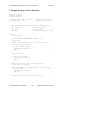
C GPIB Programming Example ........................................................ 4-37
C Example Program – NI-488.2 Routines ................................. 4-39
© National Instruments Corp.
vii
NI-488.2M Reference Manual
Contents
Chapter 5
NI-488M Software Characteristics and Functions ............. 5-1
General Programming Information ............................................ 5-1
Device Functions........................................................................ 5-1
Automatic Serial Polling ............................................................ 5-2
Compatibility ............................................................... 5-4
Internal Handler Operation .......................................... 5-4
C NI-488 I/O Calls and Functions............................... 5-5
Writing an NI-488 Program ....................................................... 5-7
Step 1 – Initializing the System ................................... 5-7
Step 2 – Clearing the Device ....................................... 5-7
Step 3 – Configuring the Device ................................. 5-8
Step 4 – Triggering the Device .................................... 5-8
Step 5 – Taking Measurements.................................... 5-8
Step 6 – Analyzing and Presenting the Acquired
Data .............................................................................. 5-9
The Complete Application Program ............................ 5-9
NI-488 Function Descriptions.................................................... 5-10
IBASK (3).................................................................... 5-11
IBBNA (3) ................................................................... 5-21
IBCAC (3) ................................................................... 5-22
IBCLR (3) .................................................................... 5-23
IBCMD (3) .................................................................. 5-24
IBCONFIG (3)............................................................. 5-26
IBDEV (3) ................................................................... 5-36
IBDMA (3) .................................................................. 5-38
IBEOS (3) .................................................................... 5-39
IBEOT (3) .................................................................... 5-42
IBFIND ........................................................................ 5-44
IBGTS (3) .................................................................... 5-46
IBIST (3)...................................................................... 5-47
IBLINES (3) ................................................................ 5-48
IBLLO (3) .................................................................... 5-50
IBLN (3) ...................................................................... 5-51
IBLOC (3).................................................................... 5-53
IBONL (3) ................................................................... 5-55
IBPAD (3).................................................................... 5-57
IBPCT (3) .................................................................... 5-59
IBPPC (3) .................................................................... 5-60
IBRD (3) ...................................................................... 5-62
IBRDF (3) .................................................................... 5-64
IBRPP (3) .................................................................... 5-66
IBRSC (3) .................................................................... 5-69
NI-488.2M Reference Manual
viii
© National Instruments Corp.
Contents
IBRSP (3) .................................................................... 5-70
IBRSV (3) .................................................................... 5-72
IBSAD (3).................................................................... 5-73
IBSGNL (3) ................................................................. 5-75
IBSIC (3) ..................................................................... 5-77
IBSRE (3) .................................................................... 5-78
IBTMO (3)................................................................... 5-79
IBTRG (3).................................................................... 5-82
IBWAIT (3) ................................................................. 5-83
IBWRT (3)................................................................... 5-86
IBWRTF (3) ................................................................ 5-88
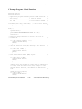
C GPIB Programming Examples ............................................... 5-90
C Example Program – Device Functions .................... 5-92
C Example Program – Board Functions ...................... 5-96
Chapter 6
ibic .......................................................................................................... 6-1
Running ibic ...................................................................................... 6-1
Using NI-488.2 Routines ........................................................... 6-2
Using Send .......................................................................... 6-3
Using Receive ..................................................................... 6-3
Using NI-488 Functions............................................................. 6-3
Using HELP ........................................................................ 6-4
Using ibfind ........................................................................ 6-4
Using ibdev ......................................................................... 6-5
Using ibwrt.......................................................................... 6-7
Using ibrd............................................................................ 6-7
How to Exit ibic ......................................................................... 6-8
Adding Common EOS Characters ............................................. 6-8
Using SET .................................................................................. 6-8
ibic Functions and Syntax ................................................................. 6-9
Status Word ....................................................................................... 6-14
Error Code ......................................................................................... 6-15
Byte Count ........................................................................................ 6-16
Auxiliary Functions........................................................................... 6-16
HELP (Display Help Information)............................................. 6-17
! (Repeat Previous Function) ..................................................... 6-17
- (Turn OFF Display) ................................................................. 6-18
+ (Turn ON Display) .................................................................. 6-18
n* (Repeat Function n Times) .................................................... 6-19
$ (Execute Indirect File) ............................................................ 6-19
PRINT (Display the ASCII String) ............................................ 6-20
© National Instruments Corp.
ix
NI-488.2M Reference Manual
Contents
E or Q (exit or quit) .................................................................... 6-20
ibic Sample Programs........................................................................ 6-20
NI-488.2 Routines ...................................................................... 6-20
Device Functions........................................................................ 6-22
Board Functions ......................................................................... 6-23
Appendix A
Multiline Interface Messages ....................................................... A-1
Appendix B
Common Errors and Their Solutions ...................................... B-1
Appendix C
Redirection to the GPIB ................................................................ C-1
Appendix D
Operation of the GPIB ................................................................... D-1
Appendix E
Customer Communication ............................................................ E-1
Glossary ................................................................................................ G-1
Index ................................................................................................ Index-1
NI-488.2M Reference Manual
x
© National Instruments Corp.
Contents
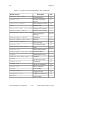
Figures
Figure 2-1.
Figure 2-2.
Upper Level of ibconf ..................................................... 2-3
Lower Level of ibconf..................................................... 2-5
Figure 3-1.
Multiboard GPIB System ................................................ 3-5
Figure D-1.
Figure D-2.
Figure D-3.
GPIB Connector and the Signal Assignment .................. D-6
Linear Configuration ....................................................... D-7
Star Configuration ........................................................... D-8
Tables
Table 2-1.
Timeout Settings ............................................................. 2-10
Table 3-1.
Table 3-2.
Table 3-3.
Status Word (ibsta) Layout ............................................. 3-7
GPIB Error Codes ........................................................... 3-11
Signal Mask Layout ........................................................ 3-19
Table 4-1.
C NI -488.2 Routines ....................................................... 4-5
Table
Table
Table
Table
Table
Table
Table
Table
Table
Table
5-1.
5-2.
5-3.
5-4.
5-5.
5-6.
5-7.
5-8.
5-9.
5-10.
C NI -488 Functions......................................................... 5-5
ibask Board Configuration Parameter Options ............... 5-13
ibask Device Configuration Parameter Options .............. 5-18
ibconfig Board Configuration Parameter Options .......... 5-28
ibconfig Device Configuration Parameter Options ......... 5-33
Data Transfer Termination Method ................................ 5-39
Parallel Poll Commands .................................................. 5-67
Signal Mask Layout ........................................................ 5-75
Timeout Code Values ...................................................... 5-79
Wait Mask Layout ........................................................... 5-83
Table
Table
Table
Table
Table
6-1.
6-2.
6-3.
6-4.
6-5.
Syntax of GPIB Functions in ibic ................................... 6-10
Syntax for NI-488.2 Routines in ibic .............................. 6-11
Status Word Layout ........................................................ 6-15
Auxiliary Functions That ibic Supports .......................... 6-16
Repeating a Previous Function........................................ 6-18
© National Instruments Corp.
xi
NI-488.2M Reference Manual
About This Manual
This manual describes the NI-488.2M software, including all NI-488.2
routines and NI-488 functions for C.
Organization of This Manual
This manual is organized as follows:
•
Chapter 1, Introduction, introduces you to the product and the manual.
•
Chapter 2, Installation and Configuration of NI-488.2M Software ,
contains the instructions for installing and configuring the NI-488.2M
software.
•
Chapter 3, Understanding the NI-488.2M Software, introduces you to
the NI-488.2 routines and NI-488 functions. It also contains
information for programming the NI-488.2 driver.
•
Chapter 4, NI-488.2M Software Characteristics and Routines, contains
a discussion of the important characteristics of the NI-488.2 routines.
This chapter also contains specific information for programming the
NI-488.2 routines in C. The descriptions are listed alphabetically for
easy reference.
•
Chapter 5, NI-488M Software Characteristics and Functions, contains
information for programming the NI-488 functions. This chapter also
contains specific information for programming the NI-488.2 functions
in C. The descriptions are listed alphabetically for easy reference.
•
Chapter 6, ibic introduces you to the Interface Bus Interactive Control
(ibic) program. This chapter also tells you how to run ibic,
summarizes the NI-488.2 and NI-488 ibic functions, and summarizes
the auxiliary functions that ibic supports.
•
Appendix A, Multiline Interface Messages, is a listing of Multiline
Interface Messages.
•
Appendix B, Common Errors and Their Solutions, singles out the most
common errors users have encountered and some possible solutions.
•
Appendix C, Redirection to the GPIB, explains how to redirect data to
a GPIB printer, plotter, or other device.
•
Appendix D, Operation of the GPIB , describes the operation of the
GPIB.
© National Instruments Corp.
xiii
NI-488.2M Reference Manual
About This Manual
•
Appendix E, Customer Communication, contains forms for you to
complete to facilitate communication with National Instruments
concerning our products.
•
The Glossary contains an alphabetical list of terms used in this manual
and a description of each.
•
The Index contains an alphabetical list of key terms and topics used in
this manual, including the pages where each one can be found.
Conventions Used in This Manual
The following conventions are used to distinguish elements of text
throughout this manual:
italic
Italic text denotes emphasis, a cross reference, or
an introduction to a key concept.
monospace
Text in this font denotes text or characters that
are to be literally input from the keyboard,
sections of code, programming examples, and
syntax examples. This font is also used for the
proper names of disk drives, paths, directories,
programs, subprograms, subroutines, device
names, functions, variables, filenames, and
extensions, and for statements and comments
taken from program code.
bold monospace
Bold text in this font denotes the messages and
responses that the computer automatically prints
to the screen.
italic monospace
Italic text in this font denotes that you must
supply the appropriate words or values in the
place of these items.
<>
Angle brackets enclose the name of a key on the
keyboard–for example, <Break>.
<->
A hyphen between two or more key names
enclosed in angle brackets denotes that you
should simultaneously press the named keys–for
example, <Ctrl-Alt-Del>.
NI-488.2M Reference Manual
xiv
© National Instruments Corp.
About This Manual
IEEE 488 and
IEEE 488.2
IEEE 488 and IEEE 488.2 refer to the
ANSI/IEEE Standard 488.1-1987 and
ANSI/IEEE Standard 488.2-1992, respectively,
which define the GPIB.
Abbreviations, acronyms, metric prefixes, mnemonics, symbols, and terms are
listed in the Glossary.
Customer Communication
National Instruments wants to receive your comments on our products and
manuals. We are interested in the applications you develop with our
products, and we want to help if you have problems with them. To make it
easy for you to contact us, this manual contains comment and configuration
forms for you to complete. These forms are in Appendix E, Customer
Communication, at the end of this manual.
© National Instruments Corp.
xv
NI-488.2M Reference Manual
Chapter 1
Introduction
Welcome to the world of the General Purpose Interface Bus (GPIB). We
believe the National Instruments family of GPIB products for your personal
computer will become a valued and integral part of your work environment.
Introduction to the GPIB
The GPIB is a link, or interface system, through which interconnected
electronic devices communicate. See Appendix D, Operation of the GPIB,
for more information about GPIB operation.
History of the GPIB
The original GPIB was designed by Hewlett-Packard (where it is called the
HP-IB) to connect and control programmable instruments manufactured by
Hewlett-Packard. Because of its high data transfer rates of up to 1 Mbyte/s,
the GPIB quickly gained popularity in other applications such as
intercomputer communication and peripheral control. It was later accepted
as the industry standard IEEE 488. The versatility of the system prompted
the name General Purpose Interface Bus.
National Instruments expanded the use of the GPIB among users of
computers manufactured by companies other than Hewlett-Packard.
National Instruments specializes both in high-performance, high-speed
hardware interfaces and in comprehensive, fullly-functioning software that
helps users bridge the gap between their knowledge of instruments and
computer peripherals and of the GPIB itself.
Background
This manual was developed as part of the documentation for the NI-488.2M
software. Software reference material can be found in this manual.
Hardware-specific information can be found in other documentation
provided with the hardware items.
© National Instruments Corp.
1-1
NI-488.2M Reference Manual
Chapter 2
Installation and Configuration of
NI-488.2M Software
This chapter contains instructions for installing and configuring the
NI-488.2M software.
Software Installation
For a list of files that will be copied from the distribution diskette and for
information on installing the software, refer to the getting started manual or
installation guide that you received with your interface board.
Software Configuration
Before you can run the software diagnostic tests, the NI-488.2M software
driver must be loaded. If you have just completed the installation procedure
and have not restarted your computer, the driver is not yet loaded.
You must run the software configuration utility ibconf (you must have
super-user privilege), because it creates all special files or device nodes
needed by the software. You can also use ibconf to inspect and modify
the default software parameters.
Refer to the ibconf section for information on ibconf and on the
configurable software options and their default values.
Board Reference Numbers
The NI-488.2M driver supports up to four interface boards. These boards
are referenced by number from your application program. The reference
number is zero (0) for the first board and one (1) for the second board. If
you installed two boards in your computer, and you do not know which
board is 0 and which board is 1, run ibconf.
© National Instruments Corp.
2-1
NI-488.2M Reference Manual
Installation and Configuration of NI-488.2M Software
Chapter 2
On some systems, ibconf will show you the relationship between the
board number and the base address of the board, thereby identifying the
board by its base address. On other systems, the relationship might be
described in terms of other settings, such as board slot number or SCSI
(small computer system interface) ID. It may be necessary for you to look
at system-specific configuration files to determine the relationship. Refer to
the Getting Started manual included with your NI-488.2M driver software
for configuration information specific to your system. Continue to the next
section, ibconf, for information on ibconf.
ibconf
ibconf is a screen-oriented, interactive program. It is largely
self-explanatory with help screens to explain all commands and options.
When used interactively, ibconf reads in the configuration parameters
from a GPIB driver file on your disk and displays them for your inspection.
You can alter any of the parameters to suit your special requirements. Once
you have finished modifying the configurable parameters, these changes
can be saved into the GPIB driver file on disk when you exit the ibconf
program.
The simplest way to use ibconf is to change to the directory that contains
the installed GPIB distribution files and enter the following command:
ibconf
Upper and Lower Levels of ibconf
ibconf operates at both an upper and a lower level. The upper level
consists of the board device maps and gives a graphical picture of the GPIB
system as defined in the driver. The lower level consists of screens
describing the individual board and devices that make up the system.
NI-488.2M Reference Manual
2-2
© National Instruments Corp.
Chapter 2
Installation and Configuration of NI-488.2M Software
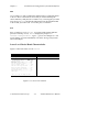
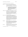
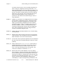
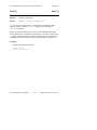
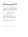
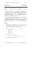
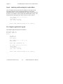
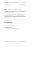
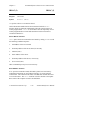
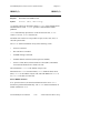
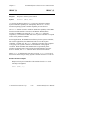
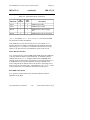
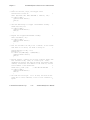
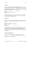
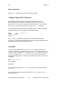
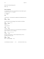
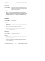
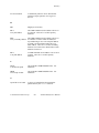
Upper Level Device Map for Board GPIBx
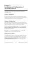
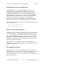
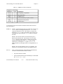
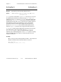
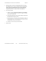
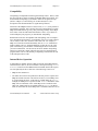
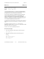
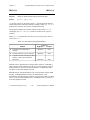
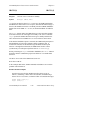
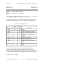
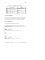
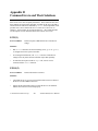
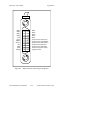
Figure 2-1 shows the upper level of ibconf.
National Instruments
Device Map for SCSI GPIB0
SPARCstation 1
* Use cursor keys h,j,k,&1 to select a device or board.
* Use control keys below to select desired action.
* Use ^B/^F to display maps for other boards.
gpib0
0 dev1
0 dev5
0 dev9
0 dev13
0 dev2
0 dev6
0 dev10
0 dev14
0 dev3
0 dev7
0 dev11
0 dev15
0 dev4
0 dev8
0 dev12
0 dev16
^Q: help
^R: rename
^T: (dis)connect
^I: edit
^O: exit
Figure 2-1. Upper Level of ibconf
As shown in Figure 2-1, the upper-level screen of ibconf displays the
names of all devices controlled by the driver. It also indicates which
devices, if any, are accessed through the interface or access board named
gpib x, where x is 0 or 1 for the two-board driver. You can move around
the map by using the cursor control keys.
The following options are available at the upper level.
•
Device Maps of the Boards
•
Help
•
Rename
•
(Dis)connect
•
Edit
•
Exit
© National Instruments Corp.
2-3
NI-488.2M Reference Manual
Installation and Configuration of NI-488.2M Software
Chapter 2
Device Maps of the Boards
Press <Control-B> or <Control-F> to toggle between the device maps for
the different GPIB interface boards. These boards are referred to as access
boards. The maps show which devices are assigned to each board. By
default, some devices are attached to the access board named gpib0, and
other devices are not attached to any board.
Help
Press <Control-Q> to access the comprehensive, online help feature of
ibconf . The help information describes the functions and common terms
associated with the upper-level of ibconf.
Rename
Press <Control-R> to rename a device.
Uppercase and lowercase letters are not treated the same. Device names
can be up to 14 characters long, but only the first seven characters will
show up in the device map.
Note:
You must not give GPIB device names the same names as files,
directories, and/or subdirectories. If you name a GPIB device
pltr and your file system contains the file pltr or a
subdirectory pltr, a conflict results. Please note that the access
board names, such as gpib0 , cannot be altered.
The string representing a device or access board name is the first variable
argument of the function ibfind called at the beginning of your
application program. Refer to Chapter 4, NI-488.2M Software
Characteristics and Routines, and Chapter 5, NI-488M Software
Characteristics and Functions of this manual for more explanations of
ibfind .
(Dis)connect
Press <Control-T> to logically connect or disconnect a device from a board.
Move the cursor to the device that is to be connected or disconnected by
using the cursor control keys and press <Control-T>.
NI-488.2M Reference Manual
2-4
© National Instruments Corp.
Chapter 2
Installation and Configuration of NI-488.2M Software
Edit
Use <Control-I> to edit or examine the characteristics of a particular board
or device. Move to the board or device that you wish to edit using the
cursor control keys and press the <Control-I> key. This step puts you in the
lower level of ibconf and lists the characteristics for the particular board
or device that you wish to edit. To exit edit, press <Control-O>.
Exit
Press <Control-Q> to exit ibconf. If you have made changes and have
pressed <Control-Q> to exit, ibconf displays the prompt Save
current configuration?. Type a y (yes) to save changes or n (no)
to lose changes. For more information, refer to the Exiting ibconf section
later in this chapter.
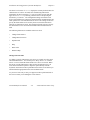
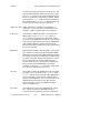
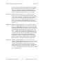
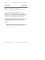
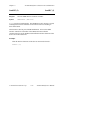
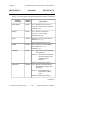
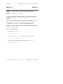
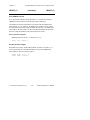
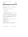
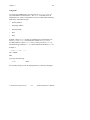
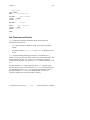
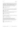
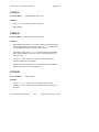
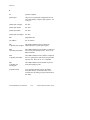
Lower Level Device/Board Characteristics
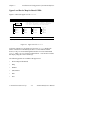
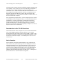
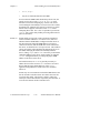
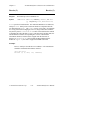
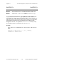
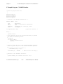
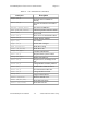
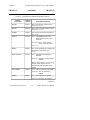
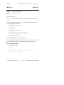
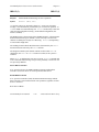
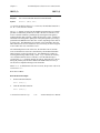
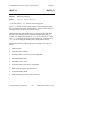
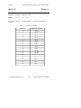
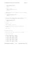
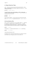
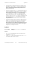
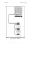
Figure 2-2 shows the lower level of ibconf.
National Instruments
Board Characteristics
Board: gpib0
SPARCstation 1
SELECT (use h or 1 key):
Primary gpib address
Secondary gpib address .........
Timeout setting ................
EOS byte .......................
Terminate read on EOS ..........
Set EOI with EOS on write ......
Type of compare on EOS .........
Set EOI w/last byte of write ...
00H
Board is system controller .....
Disable auto serial polling ....
High-speed timing ..............
UNIX signal ....................
yes
no
yes
2
00H to 1EH
NONE
T10s
00H
no
no
7-bit
yes
(Use j or k key to change fields)
^Q: help
^W: explain field
^Y: reset value
^O: return to map
Figure 2-2. Lower Level of ibconf
© National Instruments Corp.
2-5
NI-488.2M Reference Manual
Installation and Configuration of NI-488.2M Software
Chapter 2
The lower level screens of ibconf display the currently defined values for
characteristics of a device or board, such as addressing and timeout
information, as shown in Figure 2-2. You access these screens from the
upper level of ibconf by selecting a board or device and pressing the
function key <Control-I>. The configuration settings selected for each
device and each board are a means of customizing the communications and
other options to be used with that board or device. The settings for devices
specify the characteristics to be used by the access board for that device
when device functions are used. The settings for boards or devices specify
the characteristics to be used with each board when board functions are
used.
The following functions are available at the lower level:
•
Change Characteristics
•
Change Board or Device
•
Explain Field
•
Help
•
Reset Value
•
Return to Map
Change Characteristics
To change a specific characteristic of a device or a board, move the cursor
onto that characteristic. You can also press <K-Up Arrow> or <J-Down
Arrow> to move around the characteristics of a device or a board. When
the cursor is on the characteristic, either use the left/right arrow keys to
select between different options or input the option directly from the
keyboard. Instructions in the top left-hand corner of the screen inform you
which method is appropriate for the selected characteristic.
As you move from entry to entry, text appears on the top left-hand side of
the screen to assist you in making the correct choices.
NI-488.2M Reference Manual
2-6
© National Instruments Corp.
Chapter 2
Installation and Configuration of NI-488.2M Software
Help
Press <Control-Q> to access the comprehensive, online help feature of
ibconf . The help information describes the functions and common terms
associated with the lower level of ibconf.
Explain Field
Press <Control-W> to get an explanation of the field in which you are
working.
Reset Value
Press <Control-Y> to reset a characteristic option to its default value.
Return to Map
At the lower level, <Control-O> returns you to the upper level device map
of ibconf .
Default Configurations
The NI-488.2M driver has factory default configurations. For example, the
default device names of the 16 GPIB devices are dev1 through dev16.
You may want to change the names to more descriptive ones, such as
meter for a digital multimeter.
Note:
You can only connect 14 devices to each GPIB card in your
system.
You may use ibconf to look at the current default settings in the driver
file.
If you do not make changes to the NI-488.2M driver using ibconf, the
default configurations of the software remain in effect.
© National Instruments Corp.
2-7
NI-488.2M Reference Manual
Installation and Configuration of NI-488.2M Software
Chapter 2
Default Values
The following are the default values of the driver.
•
There are 16 devices with symbolic names dev1 through dev16.
•
There are two access boards with symbolic names gpib0 and gpib1 .
The access board names cannot be changed.
•
The GPIB addresses of the 16 devices are the same as the device
number. For example, dev1 is at address 1. These devices are
assigned to gpib0 as their access board.
•
Each GPIB interface board is System Controller of its independent bus
and has a GPIB address of 0.
•
The END message is sent with the last byte of each data message to a
device. No End-Of-String (EOS) character is recognized.
•
The time limit on I/O and wait function calls is set for approximately
10 s.
•
Each GPIB interface board has its own default setting for the base I/O
address and interrupt setting. Check the Getting Started manual that
came with your interface board for these settings.
Device and Board Characteristics
The following explanations are for board and device characteristics in
ibconf that are common to all revisions of the NI-488.2M driver. For
information on characteristics specific to a given driver, check the Getting
Started manual that came with your interface board. In addition, extensive
help for each characteristic is displayed on the ibconf screen while the
cursor is positioned in a field. Most of the following characteristics apply
to both devices and boards although some, as indicated, only apply to
boards.
NI-488.2M Reference Manual
2-8
© National Instruments Corp.
Chapter 2
Installation and Configuration of NI-488.2M Software
Primary GPIB Address
All devices and boards must be assigned unique primary addresses in the
range from hex 00 to hex 1E (0 to 30 decimal). The driver automatically
forms a listen address by adding hex 20 to the primary address. It forms the
talk address by adding hex 40 to the primary address. For example, a
primary address of hex 10 would have a listen address of hex 30 and a talk
address of hex 50. The GPIB primary address of any device is set within
that device, either with hardware switches or a software program. This
address and the address listed in ibconf must correspond. Refer to the
device documentation for instructions about the device address. The default
primary address of all GPIB boards is 0. There are no hardware switches
on the GPIB interface board to select the GPIB address.
Secondary GPIB Address
Any device or board using extended addressing must be assigned a
secondary address in the range from hex 60 to hex 7E (96 to 126 decimal),
or the option NONE can be selected to disable secondary addressing. As
with primary addressing, the secondary GPIB address of a device is set
within that device, either with hardware switches or a software program.
This address and the address listed in ibconf must correspond. Refer to
the device documentation for instructions about secondary addressing.
Secondary addressing is disabled for all boards and devices unless changed
in ibconf . The default option for this characteristic is NONE.
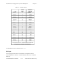
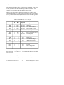
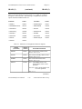
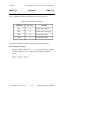
Timeout Settings
The timeout value is the approximate minimum length of time that I/O
functions such as ibrd, ibwrt, and ibcmd can take before a timeout
occurs. It is also the length of time that the ibwait function waits for an
event before returning if the TIMO bit is set in the event mask. If the SRQI
bit and TIMO bit in the event mask are passed to the ibwait function and
no SRQ is detected, the function will timeout. Refer to the IBWAIT
function description in Chapter 3, Understanding the NI-488.2M Software,
and Chapter 4, NI-488.2M Software Characteristics and Routines of this
manual for more information. This field in ibconf is set to a code
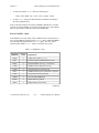
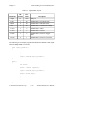
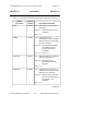
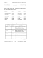
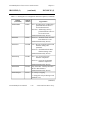
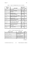
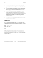
mnemonic which specifies the time limit, as shown in Table 2-1.
© National Instruments Corp.
2-9
NI-488.2M Reference Manual
Installation and Configuration of NI-488.2M Software
Chapter 2
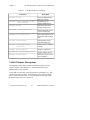
Table 2-1. Timeout Settings
Code
Actual
Value
Minimum
Timeout
TNONE
0
disabled*
T10us
1
10 µs
T30us
2
30 µs
T100us
3
100 µs
T300us
4
300 µs
T1ms
5
1 ms
T3ms
6
3 ms
T10ms
7
10 ms
T30ms
8
30 ms
T100ms
9
100 ms
T300ms
10
300 ms
T1s
11
1s
T3s
12
3s
T10s
13
10 s
T30s
14
30 s
T100s
15
100 s
T300s
16
300 s
T1000s
17
100 s
* If you select TNONE, no limit will be in effect and
I/O operations could proceed indefinitely.
The default option for this characteristic is T10s.
EOS byte
You can program some devices to terminate a read operation when a
selected character is detected. A linefeed character (hex 0A) is a common
EOS byte.
NI-488.2M Reference Manual
2-10
© National Instruments Corp.
Chapter 2
Note:
Installation and Configuration of NI-488.2M Software
The driver does not automatically append an EOS byte to the end
of data strings on write operations. You must explicitly include
this byte in your data string. The designation of the EOS byte is
only for the purpose of informing the driver of its value so that
I/O can terminate correctly.
The default option for this characteristic is 00H.
Terminate READ on EOS
Some devices send an EOS byte signaling the last byte of a data message.
A yes response to this field causes the GPIB board to terminate a read
operation when it receives the EOS byte. The default option for this
characteristic is no.
Set EOI with EOS on Write
A yes response to this field causes the GPIB board to assert the EOI line
when the EOS byte is detected on a write operation. The default option for
this characteristic is no.
Type of Compare on EOS
This field specifies the type of comparison to be made with the EOS byte.
You may indicate whether all eight bits are to be compared or just the seven
least significant bits (ASCII or ISO format). This field is only valid if a
yes response was given for either the Set EOI with EOS on Write field or
the Terminate Read on EOS field. The default option for this characteristic
is 7-bit.
Set EOI with Last Byte of Write
Some devices, as Listeners, require that the Talker terminate a data message
by asserting the EOI line with the last byte. A yes response causes the
GPIB interface board to assert the EOI line on the last data byte. The
default option for this characteristic is yes.
© National Instruments Corp.
2-11
NI-488.2M Reference Manual
Installation and Configuration of NI-488.2M Software
Chapter 2
Board Is System Controller (Board Characteristic Only)
This field appears on the board characteristics screen only. The System
Controller in a GPIB system is the device that maintains ultimate control
over the bus. There should be at most one device designated System
Controller in any GPIB system. In some situations, such as a network of
computers linked by the GPIB interface board, another device may be
System Controller and the GPIB board should be designated as not System
Controller. A no response would designate not System Controller and a
yes response would designate System Controller capability. In general,
the GPIB board should be designated as System Controller. The default
option for this characteristic is yes.
Disable Auto Serial Polling (Board Characteristic Only)
This option enables or disables automatic serial polls of devices when the
GPIB Service Request (SRQ) line is asserted. Positive poll responses are
stored following the polls and can be read with the ibrsp device function.
Refer to Chapter 5, NI-488M Software Characteristics and Functions , for
further information. Normally, this feature will not conflict with devices
that conform to the IEEE 488 specification. If there is a conflict with a
device, a y response for this field disables this feature. The default option
for this characteristic is no.
GPIB Bus Timing (Board Characteristic Only)
This field specifies the T1 delay of the board's source handshake capability.
This delay determines the minimum interval following RFD after which the
board may assert DAV during a write or command operation. If the total
length of the GPIB cable length in the system is less than 15 m, the value of
350 ns is appropriate.
There are other factors that may affect the choice of the T1 delay, although
they are unlikely to affect you. Refer to the IEEE Std. 488.1-1987,
Section 5.2, for more information about these other factors.
The default value is 500 ns.
NI-488.2M Reference Manual
2-12
© National Instruments Corp.
Chapter 2
Installation and Configuration of NI-488.2M Software
UNIX Signal (Board Characteristic Only)
This field selects the UNIX signal that would be sent as a result of the
ibsgnl function call. The default value for this characteristic is 2.
DMA Mode (Board Characteristic Only)
Data transfers can be performed either by DMA or by programmed I/O
(PIO). To disable DMA and force all read and write operations to be
performed using PIO, set this option to no. The default option for this
characteristic is yes.
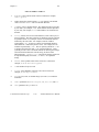
Exiting ibconf
After you have made all your changes, you can exit ibconf by pressing
<Control-O>. The program first displays the prompt Save changes?
before exiting. Typing a y response causes the changes to be written to the
file on disk and the message to be displayed:
Configuration saved.
To activate, reboot /unix.
Typing an n response causes the message Handler file unchanged
to be displayed.
Using Your NI-488.2M Software
The NI-488.2M software consists of a high-speed driver and several utilities
to help in developing and debugging an application program. The
NI-488.2M driver can be accessed in the following two ways: directly with
the NI-488 functions, or with the NI-488.2 routines.
© National Instruments Corp.
2-13
NI-488.2M Reference Manual
Installation and Configuration of NI-488.2M Software
Chapter 2
NI-488 Functions and NI-488.2 Routines
The NI-488.2M driver is a subroutine-structured device driver. The
NI-488.2M driver is faster than other available device drivers, easily
handles buffered DMA transfers and uses a structured, hierarchical
programming style familiar to users of modern programming languages.
The NI -488 functions and NI-488.2 routines are described in Chapter 3,
Understanding the NI-488.2M Software, Chapter 4, NI-488.2M Software
Characteristics and Routines, and Chapter 5, NI-488M Software
Characteristics and Functions, of this manual. An NI-488.2 or NI-488
language interface is required to link application programs to the driver.
The following is a C example of a high-level NI-488 function that writes an
array of bytes to a device:
data = "*RST; OHMS; VAL1? ";
ibwrt (scope, data, 18);
Interactive Control Program (ibic)
A good way to begin learning your GPIB system is to use the Interface Bus
Interactive Control, ibic, program described in Chapter 6, ibic. With
ibic, you can program your instruments interactively from the keyboard
rather than from an application program. Using ibic helps you quickly
understand how the instruments and the NI-488.2M driver work. It also
immediately returns the same status information that is returned as global
variables in an application program.
While running ibic, study the descriptions of each function given in
Chapter 6, ibic, to fully understand the purpose of each function or use the
online help available in ibic.
The Application Program
When you decide to write your application program, refer to Chapter 4,
NI-488.2M Software Characteristics and Routines, and Chapter 5, NI-488M
Software Characteristics and Functions , of this manual for the proper
syntax of the functions. Use ibic to test the sequence of commands your
application program uses.
NI-488.2M Reference Manual
2-14
© National Instruments Corp.
Chapter 3
Understanding the NI-488.2M Software
This chapter introduces you to two of the programming options of the
NI-488.2M software. Specifically, the NI-488.2 routines and NI-488
functions are presented to guide you as to which function set to use.
•
The NI -488.2 routines directly adhere to the Controller sequences and
protocols defined in the IEEE 488.2 1992 standard. They accept a
single device address or a list of device addresses as an input parameter
so that functions can address multiple instruments easily. These
routines give you all the advantages of IEEE 488.2.
•
The NI -488 functions have existed for many years and are the industry
standard functions for GPIB applications. They have both high-level,
device functions and low-level, board functions.
This chapter also discusses programming issues such as global variables,
error codes, read and write termination, and C programming preparations
that are common to both the NI-488.2 routines and NI-488 functions.
Introduction to the NI-488.2 Routines
A new set of NI-488.2 routines have been added to the NI-488.2M software
to take advantage of the IEEE 488.2 1992 standard. The NI-488.2 routines
are described in Chapter 4, NI-488.2M Software Characteristics and
Routines. These routines are completely compatible with the Controller
sequences and protocols defined in the IEEE 488.2 1992 standard.
IEEE 488.2 is the standard upon which the new generation of test systems
will be built because it enhances system compatibility and configurability
by defining data formats, status reporting, Controller capabilities and
commands, and a general command set to which all IEEE 488.2 instruments
must adhere. IEEE 488.2 is also the basis of the Standard Commands for
Programmable Instrumentation (SCPI), so all SCPI instruments must be
IEEE 488.2 compatible. The NI-488.2 routines address these system
programming benefits of IEEE 488.2.
© National Instruments Corp.
3-1
NI-488.2M Reference Manual
Understanding the NI-488.2M Software
Chapter 3
The syntax of the NI-488.2 routines resembles the naming conventions used
in the standard. These routines let you take full advantage of IEEE 488.2,
especially when a complete IEEE 488.2 system of Controllers and
instruments is used. There are routines that find all of the Listeners on the
bus, configure the attached instruments, find a device requesting service,
determine the state of the SRQ line, wait for SRQ to be asserted, and
address multiple devices. If your application plans call for IEEE 488.2, it is
best to use the NI-488.2 routines.
Some programming implementations, such as configuring timeout values or
monitoring all of the bus management lines, are not specifically described
in IEEE 488.2. For these requirements, the traditional NI-488 board
functions can be used along with the NI-488.2 routines. The necessary
NI-488 board functions are described in the Relationship of NI-488.2
Routines to NI-488 Calls section at the beginning of Chapter 4, NI-488.2M
Software Characteristics and Routines.
Introduction to the NI-488 Functions
The NI -488 functions consist of high-level (or device) functions that hide
much of the GPIB management operations and low-level (or board)
functions that offer you complete control over the GPIB. Typically, only a
few high-level functions are needed for most application programs. These
functions are described in Chapter 5, NI-488M Software Characteristics
and Functions.
Device Functions
Device functions are high-level functions that are easy to learn and use.
These functions free you from having to know the GPIB protocol or bus
management details involved. They automatically execute sequences of
commands that handle bus management operations required to perform
activities such as reading from and writing to devices or polling them for
status. Device functions access a specific device and take care of the
addressing and bus management protocol for that device. A descriptor of
the accessed device is one of the function's arguments.
NI-488.2M Reference Manual
3-2
© National Instruments Corp.
Chapter 3
Understanding the NI-488.2M Software
Board Functions
In contrast, board functions are low-level functions that perform
rudimentary GPIB operations. They are necessary because high-level
functions may not always meet the requirements of applications. In such
cases, low-level functions offer the flexibility to solve your application
needs.
Board functions access the GPIB interface board directly and require you to
do the addressing and bus management protocol for the bus. A descriptor
of the accessed board is one of the function's arguments.
More About Device and Board Functions
You may find it helpful to compare how a high-level device function can be
replaced by several low-level board functions. Conducting a serial poll is a
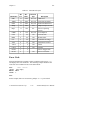
good example. In the discussion of the ibrsp function, the following C
example of the device function is used:
ibrsp (pltr,status)
This is equivalent to the following sequence using the board functions just
described:
cmd = "?!\x18G";
ibcmd (gpib0,cmd,4);
ibrd (gpib0,status,1);
cmd = "\x19_";
ibcmd (gpib0,cmd,2);
The first ibcmd function is used to send the string of ASCII commands
assigned in the first program line. These are Unlisten (?), listen address of
the board (!) with primary address 1, Serial Poll Enable ( \x18 (hex 18)),
and talk address of the plotter with primary address 7 (G). Now that the
plotter is addressed to send its status byte and the board is addressed to
receive it, the ibrd function is called to read the byte and store it in the
variable status. The final ibcmd function completes the poll by sending
the command string consisting of two messages: Serial Poll Disable (\x19
(hex 19)) and Untalk (_).
You can see that a high-level device function is easier to use. However, if
an application requires a more complex serial poll routine than the one just
described, such as one that polls several devices in succession and has other
© National Instruments Corp.
3-3
NI-488.2M Reference Manual
Understanding the NI-488.2M Software
Chapter 3
servicing operations at the same time, board functions can be used to create
such a routine.
Opening Boards and Devices
The first step when using an NI-488 function is to obtain the unit descriptor
for all boards and devices that will be used. The unit descriptor ud is the
general reference to the board or device descriptor returned by the ibfind
function or the ibdev function. A unit descriptor of a device as the first
argument in a function specifies a device function. A unit descriptor of a
board as the first argument in a function specifies a board function. Some
NI -488 functions may be both a board function and a device function.
IBFIND (board or devname, dev)
ibfind returns a unit descriptor associated with the name of boards or
devices and must be called before any other NI-488 functions. When the
software is installed, a description of each device is placed in an internal
reference table accessible by the driver. The ibfind function locates a
board or device using the symbolic names defined in the driver such as
gpib0, dev1, or scope. To find out the names of these symbols, you
can run ibconf .
Programming Features Common to NI-488.2
Routines and NI-488 Functions
This section describes programming characteristics that apply when using
either the NI-488.2 routines or the NI-488 functions.
NI-488.2M Reference Manual
3-4
© National Instruments Corp.
Chapter 3
Understanding the NI-488.2M Software
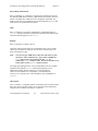
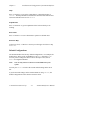
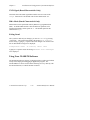
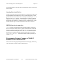
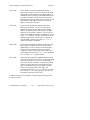
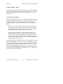
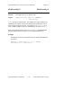
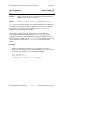
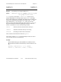
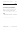
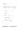
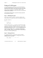
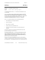
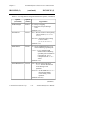
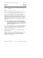
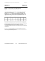
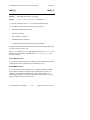
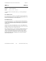
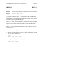
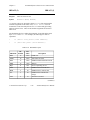
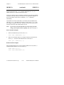
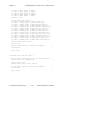
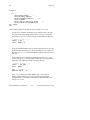
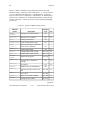
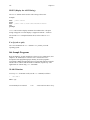
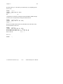
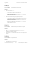
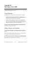
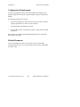
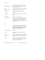
Multiboard Driver
The driver can control or manipulate more than one interface board.
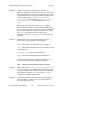
Figure 3-1 shows a multiboard GPIB system with board gpib0 connected
to two devices (an oscilloscope and a digital voltmeter) and with board
gpib1 connected to two other devices (a printer and a plotter). This type
of driver is commonly called a multiboard driver.
Boards
Devices
GPIB
Board
GPIB0
Oscilloscope
SCOPE
One
GPIB
Digital Voltmeter
DVM
GPIB
Board
GPIB1
Plotter
PLTR
Another
GPIB
Printer
PRTR
Figure 3-1. Multiboard GPIB System
© National Instruments Corp.
3-5
NI-488.2M Reference Manual
Understanding the NI-488.2M Software
Chapter 3
Learning NI-488.2 and Your Instruments
The best way to learn the NI-488.2 routines and NI-488 functions and the
commands of your instruments is interactively through your keyboard. The
Interface Bus Interactive Control (ibic) program lets you input both
NI-488 functions and NI-488.2 routines from the keyboard. You can easily
control instruments and receive status and error information without writing
an application program. ibic is described with step-by-step instructions in
Chapter 6, ibic.
General Programming Information
The following facilities or operations are common to all programming
options and languages:
•
Status Word (ibsta)
•
Error Codes (iberr)
•
Count Variables (ibcnt)
•
Read and Write Termination
You should understand these topics thoroughly to take full advantage of the
NI-488.2M driver's capabilities.
The next several paragraphs explain the status word (ibsta), the error
variable (iberr), and the count variable ( ibcnt). These variables are
updated after each function to reflect the status of the device or board just
accessed.
Status Word – ibsta
All functions return a status word containing information about the state of
the GPIB and the GPIB interface board. You can test for the conditions
reported in the status word to make decisions about continued processing.
The status word is returned in the variable ibsta. In addition, calls can be
made as functions (as opposed to subroutines) and the status word is
returned as the integer value of the function.
NI-488.2M Reference Manual
3-6
© National Instruments Corp.
Chapter 3
Understanding the NI-488.2M Software
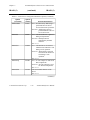
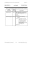
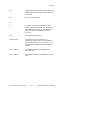
The status word contains 16 bits, of which 14 are meaningful. A bit value
of one (1) indicates that the corresponding condition is in effect. A bit
value of zero (0) indicates that the condition is not in effect.
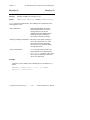
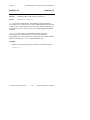
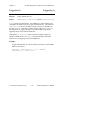
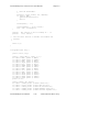
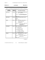
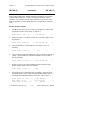
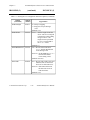
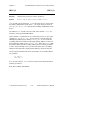
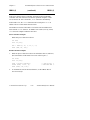
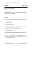
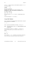
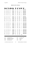
Table 3-1 lists the conditions and the bit position to be tested for each
condition. Some bits are set only on device functions (dev); some bits are
set only on board functions (brd); and some bits are set on either type (dev,
brd). The NI-488.2 routines are considered board functions.
Table 3-1. Status Word ( ibsta) Layout
Mnemonics
Bit
Pos.
Hex
Value
Function
Type
Description
ERR
15
8000
dev, brd
GPIB error
TIMO
14
4000
dev, brd
Time limit exceeded
END
13
2000
dev, brd
END or EOS detected
SRQI
12
1000
brd
SRQ interrupt received
RQS
11
800
dev
Device requesting service
CMPL
8
100
dev, brd
I/O completed
LOK
7
80
brd
Lockout state
REM
6
40
brd
Remote state
CIC
5
20
brd
Controller-In-Charge
ATN
4
10
brd
Attention is asserted
TACS
3
8
brd
Talker
LACS
2
4
brd
Listener
DTAS
1
2
brd
Device trigger state
DCAS
0
1
brd
Device clear state
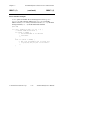
The declaration file ugpib.h for C defines the mnemonic for each bit in
the status bytes ibsta and iberr . For example, the following two calls
are equivalent:
•
if (ibsta & TACS) printf("TALK ADDRESS\n");
•
if (ibsta & 0x0008) printf("TALK ADDRESS\n");
© National Instruments Corp.
3-7
NI-488.2M Reference Manual
Understanding the NI-488.2M Software
Chapter 3
A description of each status word and its condition follows.
ERR (dev, brd)
ERR is set in the status word following any call that
results in an error; the particular error may be
determined by examining the iberr variable. ERR is
cleared following any call that does not result in an error.
Note : It is recommended that you check for an error
condition after each call. An unnoticed error
occurring early in your application program
may not become apparent until a later
instruction. At that time, the error can be more
difficult to locate.
TIMO (dev, brd) TIMO indicates whether a timeout has occurred. TIMO
is set in the status word following an ibwait if the
TIMO bit of the ibwait mask parameter is also set and
if the wait has exceeded the time limit value. TIMO is
also set following any synchronous I/O functions (for
example, ibrd, ibwrt, and ibcmd) if a timeout
occurs during a call. TIMO is cleared in the status word
in all other circumstances.
END (dev, brd)
END indicates either that the END message has been
received from the EOI line or that the driver is
configured to terminate a read function on an EOS byte
and that an EOS byte has been received following a read
function. While the GPIB board is performing a shadow
handshake as a result of the ibgts function, any other
function may return a status word with the END bit set if
the END or EOS message occurred before or during that
call. END is cleared in the status word when any I/O
operation is initiated.
SRQI (brd)
SRQI specifies that some device is requesting service.
SRQI is set in the status word whenever the GPIB board
is CIC, the GPIB SRQ line is asserted, and the automatic
serial poll capability is disabled. SRQI is cleared
whenever the GPIB board ceases to be the CIC, or the
GPIB SRQ line is unasserted.
RQS (dev)
RQS appears only in the status word of a device function
and indicates that the device is requesting service. RQS
is set in the status word whenever the hex 40 bit is
NI-488.2M Reference Manual
3-8
© National Instruments Corp.
Chapter 3
Understanding the NI-488.2M Software
asserted in the serial poll status byte of the device. The
serial poll that obtains the status byte may be the result
of an ibrsp, or the poll may be done automatically by
the driver if automatic serial polling is enabled. RQS is
cleared when an ibrsp reads the serial poll status byte
that caused the RQS. An ibwait on RQS should only
be done on devices that respond to serial polls.
CMPL (dev, brd) CMPL indicates the condition of outstanding I/O
operations. It is set in the status word whenever I/O is
complete. CMPL is cleared while I/O is in progress.
LOK (brd)
LOK indicates whether the board is in a lockout state.
While LOK is set, the EnableLocal routine or
ibloc function is inoperative for that board. LOK is
set whenever the GPIB board detects the Local Lockout
(LLO) message has been sent either by the GPIB board
or by another Controller. LOK is cleared when the
Remote Enable (REN) GPIB line becomes unasserted by
the System Controller.
REM (brd)
REM indicates whether or not the board is in the remote
state. REM is set whenever the Remote Enable (REN)
GPIB line is asserted and the GPIB board detects that its
listen address has been sent either by the GPIB board or
by another Controller. REM is cleared whenever REN
becomes unasserted, or when the GPIB board as a
Listener detects the Go to Local (GTL) command has
been sent either by the GPIB board or by another
Controller, or when the ibloc function is called while
the LOK bit is cleared in the status word.
CIC (brd)
CIC indicates whether the GPIB board is the ControllerIn-Charge. CIC is set whenever the SendIFC routine
or ibsic function is executed while the GPIB board is
System Controller or when another Controller passes
control to the GPIB board. CIC is cleared whenever the
GPIB board detects Interface Clear (IFC) from the
System Controller, or when the GPIB board passes
control to another device.
ATN (brd)
ATN indicates the state of the GPIB Attention (ATN)
line. ATN is set whenever the GPIB ATN line is
asserted and cleared when the ATN line is unasserted.
© National Instruments Corp.
3-9
NI-488.2M Reference Manual
Understanding the NI-488.2M Software
Chapter 3
TACS (brd)
TACS indicates whether the GPIB board has been
addressed as a Talker. TACS is set whenever the GPIB
board detects its talk address (and secondary address, if
enabled) has been sent either by the GPIB board itself or
by another Controller. TACS is cleared whenever the
GPIB board detects the Untalk (UNT) command, its own
listen address, a talk address other than its own talk
address, or Interface Clear (IFC).
LACS (brd)
LACS indicates whether the GPIB board has been
addressed as a Listener. LACS is set whenever the
GPIB board detects its listen address (and secondary
address, if enabled) has been sent either by the GPIB
board itself or by another Controller. LACS is also set
whenever the GPIB board shadow handshakes as a result
of the ibgts function. LACS is cleared whenever the
GPIB board detects the Unlisten (UNL) command, its
own talk address, Interface Clear (IFC), or ibgts is
called without shadow handshake.
DTAS (brd)
DTAS indicates whether the GPIB board has detected a
device trigger command. DTAS is set whenever the
GPIB board, as a Listener, detects the Group Execute
Trigger (GET) command has been sent by another
Controller. DTAS is cleared in the status word on any
call immediately following an ibwait call if the DTAS
bit is set in the ibwait mask parameter.
DCAS (brd)
DCAS indicates whether the GPIB board has detected a
device clear command. DCAS is set whenever the GPIB
board detects the Device Clear (DCL) command has
been sent by another Controller, or whenever the GPIB
board as a Listener detects the Selected Device Clear
(SDC) command has been sent by another Controller.
DCAS is cleared in the status word on any call
immediately following an ibwait call if the DCAS bit
was set in the ibwait mask parameter, or on any call
immediately following a read or write.
In addition to the previous conditions, the following situations also affect
the status word bits:
NI-488.2M Reference Manual
3-10
© National Instruments Corp.
Chapter 3
•
Understanding the NI-488.2M Software
A call to the function ibonl clears the following bits:
END LOK REM CIC TACS LACS DTAS DCAS
•
A call to ibonl affects bits other than those listed here according to
the rules explained above.
In the event that a function call returns an ENEB or EDVR error, all status
word bits except the ERR bit are cleared, because these error codes indicate
that it is not possible to obtain the status of the GPIB board.
Error Variable – iberr
If the ERR bit is set in the status word, a GPIB error has occurred; that is, if
the previous GPIB call returned with an ibsta value in which the ERR bit
is set, the following interpretations of iberr apply. The error code is
returned in the variable iberr. Table 3-2 lists these error codes.
Table 3-2. GPIB Error Codes
Suggested
Mnemonic
Decimal
Value
EDVR
0
UNIX error (code in ibcnt)
ECIC
1
Function requires GPIB board to be CIC
ENOL
2
Write handshake error (e.g., no Listener)
EADR
3
GPIB board not addressed correctly
EARG
4
Invalid argument to function call
ESAC
5
GPIB board not System Controller as required
EABO
6
I/O operation aborted (timeout)
ENEB
7
Non-existent GPIB board
EDMA
8
DMA hardware problem
EBTO
9
DMA hardware bus timeout
Explanation
(continues)
© National Instruments Corp.
3-11
NI-488.2M Reference Manual
Understanding the NI-488.2M Software
Chapter 3
Table 3-2. GPIB Error Codes (Continued)
Suggested
Mnemonic
Decimal
Value
ECAP
11
No capability for operation
EFSO
12
File system error
EBUS
14
GPIB bus error
ESTB
15
Serial Poll status byte queue overflow
ESRQ
16
SRQ stuck in ON position
ETAB
20
Table Problem
Explanation
A description of each error and some conditions under which each error
may occur follows:
EDVR (0)
EDVR is returned when the device or board name passed in an
ibfind call is not configured in the driver. ibcnt will
contain the UNIX error code. The remedy is to replace the
argument to ibfind with a valid board or device name or to
reconfigure the driver using the ibconf utility to recognize
the name.
EDVR is also returned when an invalid unit descriptor is
passed to any function call. The remedy is to be sure that
ibfind has been called and that it completed successfully.
Also note that following a call to ibonl with a second
argument of 0, which places brd offline, an ibfind is
required before any subsequent calls to or using that device or
board.
EDVR is also returned when the driver is not installed. The
remedy is to verify that the software was installed correctly.
ECIC (1)
ECIC is returned when one of the following board functions
or routines is made while the board is not CIC:
•
Any of the NI-488.2 routines
•
Any board functions that put command bytes on the GPIB
bus: ibcmd , ibln, ibrpp
NI-488.2M Reference Manual
3-12
© National Instruments Corp.
Chapter 3
Understanding the NI-488.2M Software
•
ibcac, ibgts
•
Any device functions that affect the GPIB
In cases when the GPIB board should always be the CIC, the
remedy is to be sure to call SendIFC or ibsic to send
Interface Clear before attempting any of these calls, and to
avoid sending the command byte TCT (hex 09, Take Control).
In multiple CIC situations, the remedy is to always be certain
that the CIC bit appears in the status word ibsta before
attempting these calls. If it is not, it is possible to perform an
ibwait (CIC) call to delay further processing until control is
passed to the board.
ENOL (2)
ENOL usually occurs when a write operation is attempted
with no Listeners addressed. For a device write, this error
indicates that the GPIB address configured for that device in
the driver does not match the GPIB address of any device
connected to the bus, that the GPIB cable is not connected to
the device, or that the device is not powered on. This situation
can be corrected by either attaching the appropriate device to
the GPIB, modifying the address of an already attached
device, calling ibpad (and ibsad if necessary) to match the
configured address to the device switch settings, or using the
ibconf configuration utility to reassign the proper GPIB
address to the device in the driver.
For board functions, an ibcmd is generally necessary to
address devices before a board ibwrt function is executed.
Be sure that the proper listen address is in the ibcmd
argument string and that no Unlisten (hex 3F) command
follows it.
ENOL may occur in situations in which the GPIB board is not
the CIC and the Controller asserts ATN before the write call
in progress has ended. The remedy is either to reduce the
write byte count to that which is expected by the Controller, or
to resolve the situation on the Controller's end.
© National Instruments Corp.
3-13
NI-488.2M Reference Manual
Understanding the NI-488.2M Software
EADR (3)
Chapter 3
EADR occurs when the GPIB board is CIC and is not
addressing itself before read and write functions. This error is
extremely unlikely to occur on a device function. For a board
function the remedy is to be sure to send the appropriate Talk
or Listen address using SendCmds, SendSetup, or
ReceiveSetup before attempting SendDataBytes or
RcvRespMsg; or ibcmd before attempting ibwrt or
ibrd.
EADR is also returned by the function ibgts when the
shadow-handshake feature is requested and the GPIB ATN
line is already unasserted. In this case, the shadow handshake
is not possible and the error is returned to notify you of that
fact. ibgts should almost never be called except
immediately after an ibcmd call. (ibcmd causes ATN to be
asserted.)
EARG (4)
EARG results when an invalid argument is passed to a
function call. The following are some examples:
ibtmo called with a value not in the range 0 through 17.
ibeos called with meaningless bits set in the high byte of the
second parameter.
ibpad or ibsad called with invalid addresses.
ibppc called with invalid parallel poll configurations.
A board function made with a valid device descriptor, or a
device function made with a valid board descriptor.
Note :
EDVR is returned if the descriptor is invalid.
ESAC (5)
ESAC results when SendIFC , ibsic, EnableRemote, or
ibsre is called when the GPIB board does not have System
Controller capability. The remedy is to give the GPIB board
that capability by calling ibrsc or by using ibconf to
configure that capability into the driver.
EABO (6)
EABO indicates that I/O has been canceled, usually due to a
timeout condition. Another cause is receiving the Device
Clear message from the CIC.
NI-488.2M Reference Manual
3-14
© National Instruments Corp.
Chapter 3
Understanding the NI-488.2M Software
To remedy a timeout error, if I/O is actually progressing but
times out anyway, lengthen the timeout period with ibtmo.
More frequently, however, the I/O is stuck (the Listener is not
continuing to handshake or the Talker has stopped talking), or
the byte count in the call which timed out was more than the
other device was expecting. Be sure that both parties to the
transfer understand what byte count is expected; or, if
possible, have the Talker use the END message to assist in
early termination.
ENEB (7)
ENEB occurs when there is no GPIB board at the I/O address
specified in the configuration program. This happens when
the board is not physically plugged into the system, the I/O
address specified during configuration does not match the
actual board setting, or there is a conflict in the system with
the base I/O address. If there is a mismatch between the
actual board setting and the value specified at configuration
time, either reconfigure the software or change the board
switches to match the configured value.
EDMA (8)
EDMA indicates that a DMA hardware error occurred during
an I/O operation.
EBTO (9)
EBTO indicates that a hardware bus timeout occurred during
an I/O operation. This is usually the result of an attempt by a
DMA Controller to access non-existent memory.
ECAP (11) ECAP results when a particular capability has been disabled in
the driver and a call is made that attempts to make use of that
capability.
EFSO (12)
EFSO results when an ibrdf or ibwrtf call encounters a
problem performing a file operation. Specifically, this error
indicates that the function is unable to open, create, seek,
write, or close the file being accessed. The specific error
code for this condition is contained in ibcnt.
EBUS (14) EBUS results when certain GPIB bus errors occur during
device functions. All device functions send command bytes to
perform addressing and other bus management. Devices are
expected to accept these command bytes within the time limit
specified by the configuration program or by ibtmo. EBUS
occurs if a timeout occurred during the sending of these
command bytes. Under normal operating circumstances, the
© National Instruments Corp.
3-15
NI-488.2M Reference Manual
Understanding the NI-488.2M Software
Chapter 3
remedy would be to find out which GPIB device is accepting
commands abnormally slow and fix the problem with that
device. In situations in which slow handshaking of the
commands is desirable, lengthen the board time limit either
with the configuration program or the ibtmo function.
ESTB (15)
ESTB occurs only during the ibrsp function. ESTB
indicates that one or more serial poll status bytes that were
received due to automatic serial polls have been discarded for
lack of room to store them. Several older status bytes are
available; however, the oldest is being returned by the ibrsp
call. If your application cannot tolerate missing even one
status byte, the remedy is to disable Automatic Serial Polling
using ibconf.
ESRQ (16) ESRQ occurs only during the WaitSRQ routine or ibwait
function. ESRQ indicates that a wait for RQS is not possible
because the GPIB SRQ line is stuck on. The usual reason for
this situation is that some device that the driver is unaware of
is asserting SRQ. Because the driver does not know of this
device, it will never be serial polled and SRQ will never go
away. Another reason for this error is that a GPIB bus tester
or similar equipment was forcing the SRQ line to be asserted
or that there is a cable problem involving the SRQ line.
Although the occurrence of ESRQ signals a definite GPIB
problem, it does not affect GPIB operations, except that the
RQS bit cannot be depended on while the condition lasts.
ETAB (20) ETAB occurs only during the FindLstn and FindRQS
routines. ETAB indicates that there was some problem with a
table used by these functions. In the case of FindLstn, this
is not an error condition but simply an advisory message
which means that the given table did not have enough room to
hold all the addresses of the Listeners found. In the case of
FindRQS, it means that none of the devices in the given table
were requesting service.
NI-488.2M Reference Manual
3-16
© National Instruments Corp.
Chapter 3
Understanding the NI-488.2M Software
Count Variable – ibcnt
The count variable is updated after each read, write, or command function
with the number of bytes actually transferred by the operation. The count
variable is also updated by many of the NI-488.2 routines. ibcnt is an
integer value.
Read and Write Termination
The IEEE 488 specification defines two methods of identifying the last byte
of device-dependent (data) messages. The two methods permit a Talker to
send data messages of any length without the Listener(s) knowing in
advance the number of bytes in the transmission. The two methods are as
follows:
•
END message. In this method, the Talker asserts the EOI (End Or
Identify) signal simultaneously with transmission of the last data byte.
By design, the Listener stops reading when it detects a data message
accompanied by EOI, regardless of the value of the byte.
•
End-Of-String (EOS) character. In this method, the Talker uses a
special character at the end of its data string. With IEEE 488.2, this
EOS character is explicitly designated as a new line (NL, ASCII 10,
hex 0A) character. By prior arrangement, the Listener stops receiving
data when it detects that character. Either a 7-bit ASCII character or a
full 8-bit binary byte can be used.
The NI-488.2M driver terminates reads and writes according to the value of
the termination parameter. For reads, STOPend will terminate the read
operation on the END message. If the termination parameter is a character,
the read operation terminates when that character is received. For writes,
the termination parameter may be either NLend, DABend, or NULLend.
NLend sends NL with END after the last data byte has been sent; DABend
sends END with the last data byte to be sent; and NULLend simply sends
the data bytes with no END message.
© National Instruments Corp.
3-17
NI-488.2M Reference Manual
Understanding the NI-488.2M Software
Chapter 3
C Programming Information
The following discussion contains information for programming the driver
functions in C.
C Language Files
The NI -488 software distribution medium contains the following files
which are relevant to programming in C:
•
ugpib.h is a file containing useful variable and constant declarations.
•
cib.c (or in some cases, cib.o) is the C language interface library
for the NI-488.2 functions.
Programming Preparations for C
Include the following C statement at the beginning of your application
program:
#include "ugpib.h"
The compiled C application program written is linked with cib.o to
produce an executable file. Refer to the Getting Started manual included
with your NI-488.2M driver for instructions on creating and using the
cib.o file.
Signal Interrupting
C programs may be signaled on the occurrence of a GPIB event. When the
signal occurs, the program goes to a user-specified signal handler. The
signal handler is attached using the UNIX signal function. The default
signal to be raised is SIGINT and may be changed using the ibconf utility.
A special function, ibsgnl, is used to make the NI-488.2M driver assert a
UNIX signal on the occurrence of a GPIB event. The ibsgnl function is
a board-level function that is passed a bit mask that specifies which events
are to raise the signal. A mask bit is set to request a signal when the
corresponding event occurs. A mask of zero disables signals. Table 3-3
displays the recognized bits.
NI-488.2M Reference Manual
3-18
© National Instruments Corp.
Chapter 3
Understanding the NI-488.2M Software
Table 3-3. Signal Mask Layout
Mnemonic
Bit
Position
Hex
Value
SRQI
12
1000
LOK
7
80
GPIB board is in Lockout State
REM
6
40
GPIB board is in Remote State
CIC
5
20
GPIB board is Controller-In-Charge
TACS
3
8
GPIB board is Talker
LACS
2
4
GPIB board is Listener
DTAS
1
2
GPIB board is in Device Trigger
State
DCAS
0
1
GPIB board is in Device Clear State
Description
SRQ on
The following is an example program that handles the SIGINT UNIX signal
when the SRQI GPIB event occurs:
void signal_handler()
{
.
.
.
signal (SIGINT,signal_handler);
}
main()
{
int board;
board = ibfind ("gpib0");
signal (SIGINT,signal_handler);
ibsgnl (board,SRQI);
.
.
.
}
© National Instruments Corp.
3-19
NI-488.2M Reference Manual
Understanding the NI-488.2M Software
Chapter 3
The next two chapters describe in detail the NI-488.2 routines and
NI-488 functions, respectively. Complete descriptions of each routine and
function are given and example code and programs are shown.
NI-488.2M Reference Manual
3-20
© National Instruments Corp.
Chapter 4
NI-488.2M Software Characteristics
and Routines
This chapter contains a discussion of the important characteristics of the
NI-488.2 routines available in the driver that are common to all
programming languages. It also describes the calling syntax for the
procedures in C.
Overview
The IEEE 488.2 1992 specification explains in greater detail than the earlier
IEEE 488.1 specification the exact ways in which the GPIB is to be
managed by the Controller, the standard messages that compliant devices
should understand, the mechanisms by which device errors and other status
information are to be reported, and various protocols aimed at discovering
what compliant devices are connected to the bus and configuring these
devices.
To be fully compliant with the IEEE 488.2 protocol, the latest revisions of
many National Instruments GPIB interface boards are now fully compatible
with the more stringent requirements of the IEEE 488.2 specification. In
addition, routines have been added to the driver. By using these routines,
you can have a programming interface that closely resembles the
descriptions found in the IEEE 488.2 specification document, and that
strictly adheres to the command and data sequences found there.
Using National Instruments NI-488.2 routines together with compliant
488.2-compatible devices can result in greater predictability of instrument
behavior and programming correctness, and increased similarity in the ways
that instruments of different manufacturers are programmed.
General Programming Information
The NI -488.2 routines use the Controller protocols and procedures
described in the IEEE 488.2 specification. The calling syntax of the
routines is intended to closely resemble the implementations suggested in
that specification document.
© National Instruments Corp.
4-1
NI-488.2M Reference Manual
NI-488.2M Software Characteristics and Routines
Chapter 4
The NI-488.2 set of routines consists of the following routines, whose
functionality can be broken down into the following groups:
•
Simple Device I/O
- Send
- Receive
•
Multiple Device I/O
- SendList
•
Simple Device Control
-
•
Multiple Device Control
-
•
TriggerList
DevClearList
EnableRemote
EnableLocal
FindRQS
AllSpoll
Bus Management
-
•
Trigger
DevClear
ReadStatusByte
PPoll
PPollConfig
PPollUnconfig
PassControl
ResetSys
SendIFC
FindLstn
TestSRQ
WaitSRQ
TestSys
SendLLO
SetRWLS
Low-level I/O
- SendCmds
- SendDataBytes
NI-488.2M Reference Manual
4-2
© National Instruments Corp.
Chapter 4
NI-488.2M Software Characteristics and Routines
- SendSetup
- RcvRespMsg
- ReceiveSetup
The Simple Device I/O routines can read and write to individual GPIB
devices.
The Multiple Device I/O routines can write the same message to multiple
Listeners with a single message transmission.
The Simple Device Control routines direct various bus management
instructions to individual devices.
The Multiple Device Control routines direct bus management instructions
to multiple devices in the same message.
The Bus Management routines cause system-wide functions to be
performed, or provide system-wide status.
The Low-Level I/O routines are used to break down a higher-level routine
into more detailed instructions due to unusual situations.
All routines take, as their first parameter, a board number selecting a GPIB
interface board installed in the computer. For the majority of cases, there
will be only one GPIB interface board installed, and its board number will
be 0. Therefore, in the typical case, a 0 is the first argument of all
NI-488.2 routines.
Routines that operate on single devices have, as their second parameter, an
integer that indicates the GPIB address of the device. In the typical case of
a device that uses only primary GPIB addressing, this involves passing a
simple integer in the range 0 to 30, corresponding to the primary GPIB
address of the device. In the more unusual case of a device with both a
primary and a secondary address, the two addresses are packed into an
integer with the primary address in the lower byte and the secondary
address in the higher byte. In C, such integers would resemble, for
example, 6103, which indicates a device whose primary address is 3 and
whose secondary address is hex 61.
Routines that operate on multiple devices have, as their second parameter,
an integer array containing the addresses in question. The individual
addresses are formed in the same way as described in the previous
paragraph for the single-device routines, except that they are placed in
© National Instruments Corp.
4-3
NI-488.2M Reference Manual
NI-488.2M Software Characteristics and Routines
Chapter 4
consecutive elements of an integer array, followed by a special value,
NOADDR , to mark the end of the addresses.
I/O routines contain a buffer argument and, in some languages, a count
argument. If present, the count argument may be specified as either an
integer or a long integer (if allowed by the language.)
Some routines require other parameters to fulfill particular specialized
needs of the routine.
Relationship of NI-488.2 Routines to NI-488 Calls
The NI-488.2 routines have a complete set of Controller procedures and
protocols as defined in IEEE 488.2. There are cases, however, where more
detailed control of the GPIB is required, in ways that are outside the scope
of the IEEE 488.2 standard. These situations include the following:
•
Communicating with non-compliant (non-IEEE 488.2) devices
•
Altering various low-level board configurations
•
Managing the bus in non-typical ways
The original National Instruments NI-488 board functions are compatible
with, and can be interspersed within, sequences of NI-488.2 routines. For
example, a call to ibtmo can be issued within sequences of NI-488.2
routines to alter the timeout value; a call to iblines can be issued to
monitor the state of any given GPIB line, and so on. To make these calls
from within a sequence of NI-488.2 routines, the usual call to ibfind is
not required; merely substitute the board number as the first parameter of
the NI-488 board function. Thus, all calls in the sequence, both
NI-488.2 and NI-488, will have the same board number (usually 0) as the
first parameter. Using these calls as needed within an NI-488.2 program
ensures that non-standard or unusual situations or devices can be dealt with
easily.
NI-488.2M Reference Manual
4-4
© National Instruments Corp.
Chapter 4
NI-488.2M Software Characteristics and Routines
Timeouts
Most of the NI-488.2 routines, particularly those involving the transfer of
command sequences or data messages, are regulated by the same timeout
mechanism that regulates the NI-488 calls. A default timeout period of 10
seconds is preconfigured in the driver; thus, all I/O must complete within
that period to avoid a timeout error. In addition, the WaitSRQ routine
waits for this period before returning with a “no SRQ” indication. The
default timeout value can be changed with the ibconf utility. In addition,
you can use the NI-488 board function call ibtmo to programmatically
alter the timeout period. Refer to the description of the ibtmo function in
Chapter 5, NI-488M Software Characteristics and Functions for more
information.
Regardless of the I/O and Wait timeout period, a much shorter timeout is
enforced for responses to serial polls. This shorter timeout period takes
effect whenever a serial poll is conducted. Because devices normally
respond quickly to polls, there is no need to wait for the relatively lengthy
I/O timeout period for a non-responsive device.
C NI-488.2 Routines
Table 4-1 lists the call syntax for each NI-488.2 routine and a brief
description of these routines for C.
Table 4-1. C NI-488.2 Routines
Call Syntax
Description
AllSpoll (board,addresslist,
resultlist)
Serial poll all devices
DevClear (board,address)
Clear a single device
DevClearList (board,addresslist)
Clear multiple devices
EnableLocal (board,addresslist)
Enable operations from
the front of a device
EnableRemote (board,addresslist)
Enable remote GPIB
programming of devices
(continues)
© National Instruments Corp.
4-5
NI-488.2M Reference Manual
NI-488.2M Software Characteristics and Routines
Chapter 4
Table 4-1. C NI-488.2 Routines (Continued)
Call Syntax
Description
FindLstn (board,addresslist,
resultlist,limit)
Find all Listeners
FindRQS (board,addresslist,result)
Determine which device is
requesting service
PassControl (board,address)
Pass control to another
device with Controller
capability
PPoll (board,result)
Perform a parallel poll
PPollConfig (board,address,
dataline,sense)
Configure a device for
parallel polls
PPollUnconfig (board,addresslist)
Unconfigure devices for
parallel polls
RcvRespMsg (board,data,termination)
Read data bytes from
already addressed device
ReadStatusByte (board,address,
result)
Serial poll a single device
to get its status byte
Receive (board,address,count,
termination)
Read data bytes from a
GPIB device
ReceiveSetup (board,address)
Prepare a particular device
to send data bytes and
prepare the GPIB board to
read them
ResetSys (board,addresslist)
Initialize a GPIB system
on three levels
Send (board,address,data,eotmode)
Send data bytes to a single
GPIB device
SendCmds (board,commands,count)
Send GPIB command
bytes
SendDataBytes (board,data,count
eotmode)
Send data bytes to already
addressed devices
(continues)
NI-488.2M Reference Manual
4-6
© National Instruments Corp.
Chapter 4
NI-488.2M Software Characteristics and Routines
Table 4-1. C NI-488.2 Routines (Continued)
Call Syntax
Description
SendIFC (board)
Clear the GPIB interface
functions with IFC
SendList (board,addresslist,data,
count,eotmode)
Send data bytes to
multiple GPIB devices
SendLLO (board)
Send the local lockout
message to all devices
SendSetup (board,addresslist)
Prepare particular devices
to receive data bytes
SetRWLS (board,addresslist)
Place particular devices in
the Remote with Lockout
state
TestSRQ (board,result)
Determine the current
state of the SRQ line
TestSys (board,addresslist,
resultlist)
Cause devices to conduct
self-tests
Trigger (board,address)
Trigger a single device
Triggerlist (board,addresslist)
Trigger multiple devices
WaitSRQ (board,result)
Wait until a device asserts
Service Request
NI-488.2 Routine Descriptions
The remainder of this chapter contains a detailed description of each
NI-488.2 routine with examples in C. The descriptions are listed
alphabetically for easy reference.
To the right of each routine, notice the number 3 in parentheses (3). This
number is a UNIX convention. It identifies the type of function (in this
case, a routine) and also refers you to a particular section in your UNIX
Reference Pages (in this case, Section 3).
© National Instruments Corp.
4-7
NI-488.2M Reference Manual
NI-488.2M Software Characteristics and Routines
AllSpoll (3)
Chapter 4
AllSpoll (3)
Purpose:
Serial Poll all devices.
Syntax:
void AllSpoll (int board, Addr4882_t addresslist [],
short resultlist [] )
board specifies a board number. The GPIB devices whose addresses are
contained in the address array are serial polled, and the responses are stored
in the corresponding elements of the resultlist array. The parameter
addresslist is an array of address integers of any size, terminated by
the value NOADDR.
If any of the specified devices times out instead of responding to the poll,
then the error code EABO is returned in iberr , and ibcnt contains the
index of the timed-out device.
Although the AllSpoll routine is general enough to serial poll any
number of GPIB devices, the ReadStatusByte routine should be used
in the case of polling exactly one GPIB device.
Example:
Serial poll two devices connected to board 0 whose GPIB addresses are
8 and 9.
Addr4882_t addresslist[3] = {8, 9, NOADDR};
short resultlist[2];
AllSpoll (0, addresslist, resultlist);
NI-488.2M Reference Manual
4-8
© National Instruments Corp.
Chapter 4
NI-488.2M Software Characteristics and Routines
DevClear (3)
DevClear (3)
Purpose:
Clear a single device.
Syntax:
void DevClear ( int board, Addr4882_t address)
board specifies a board number. The GPIB Selected Device Clear (SDC)
message is sent to the device at the given address. The parameter
address contains in its low byte the primary GPIB address of the device
to be cleared. The high byte should be 0 if the device has no secondary
address. Otherwise, it should contain the desired secondary address. If
address contains the constant value NOADDR, the Universal Device Clear
message is sent to all devices on the GPIB.
The DevClear routine is used to clear either exactly one GPIB device, or
all GPIB devices. To send a single message that clears several particular
GPIB devices, use the DevClearList routine.
Example:
Clear a digital voltmeter connected to board 0 whose primary GPIB
address is 9 and whose secondary GPIB address is 97.
DevClear (0, MakeAddr (9, 97));
/* In C, a macro has been defined in the header
* file ugpib.h, MakeAddr(p, s), which can be
* used to pack the primary and secondary
* addresses into the correct form.
*/
© National Instruments Corp.
4-9
NI-488.2M Reference Manual
NI-488.2M Software Characteristics and Routines
DevClearList (3)
Chapter 4
DevClearList (3)
Purpose:
Clear multiple devices.
Syntax:
void DevClearList (int board, Addr4882_t addresslist [])
board specifies a board number. The GPIB devices whose addresses are
contained in the address array are cleared. The parameter addresslist
is an array for any size of address integers, terminated by the value
NOADDR .
Although the DevClearList routine is general enough to clear any
number of GPIB devices, the DevClear routine should be used in the
common case of clearing exactly one GPIB device.
If the array contains only the value NOADDR or NULL, the universal Device
Clear message is sent.
Example:
Clear two devices connected to board 0 whose GPIB addresses are 8
and 9.
Addr4882_t addresslist[3] = {8, 9, NOADDR};
DevClearList (0, addresslist);
NI-488.2M Reference Manual
4-10
© National Instruments Corp.
Chapter 4
NI-488.2M Software Characteristics and Routines
EnableLocal (3)
EnableLocal (3)
Purpose:
Enable operations from the front panel of a device.
Syntax:
void EnableLocal (int board, Addr4882_t addresslist [])
board specifies a board number. The GPIB devices whose addresses are
contained in the addresslist array are placed in local mode by
addressing the devices as Listeners and sending the GPIB Go To Local
command. The parameter addresslist is an array for any size of
address integers, terminated by the value NOADDR.
If the array contains only the value NOADDR or NULL, Remote Enable
(REN) becomes unasserted, immediately placing all GPIB devices in local
mode.
Example:
Place the devices at GPIB addresses 8 and 9 in local mode.
Addr4882_t addresslist[3] = {8, 9, NOADDR};
EnableLocal (0, addresslist);
© National Instruments Corp.
4-11
NI-488.2M Reference Manual
NI-488.2M Software Characteristics and Routines
EnableRemote (3)
Chapter 4
EnableRemote (3)
Purpose:
Enable remote GPIB programming of devices.
Syntax:
void EnableRemote (int board, Addr4882_t addresslist [] )
board specifies a board number. The GPIB devices whose addresses are
contained in the addresslist array are placed in remote mode by
asserting Remote Enable (REN) and addressing the devices as Listeners.
The parameter addresslist is an array for any size of address integers,
terminated by the value NOADDR.
If the array contains only the value NOADDR or NULL for addresslist ,
no addressing is performed, and Remote Enable (REN) becomes asserted.
Example:
Place the devices at GPIB addresses 8 and 9 in remote mode.
Addr4882_2 addresslist[3] = {8, 9, NOADDR};
EnableRemote (0, addresslist);
NI-488.2M Reference Manual
4-12
© National Instruments Corp.
Chapter 4
NI-488.2M Software Characteristics and Routines
FindLstn (3)
FindLstn (3)
Purpose:
Find all Listeners.
Syntax:
void FindLstn (int board, Addr4882_t addresslist [ ] ,
Addr4882_t resultlist [ ] , int limit)
board specifies a board number. addresslist contains a list of
primary GPIB addresses, terminated by the value NOADDR. These
addresses are tested in turn for the presence of a listening device. If found,
the addresses are entered into the resultlist. If no listening device is
detected at a particular primary address, all the secondary addresses
associated with that primary address are tested, and detected Listeners are
entered into resultlist. The limit argument specifies how many
entries should be placed into the resultlist array. If more Listeners
are present on the bus, the list is truncated after limit entries have been
detected, and the error ETAB will be reported in iberr. The variable
ibcnt will contain the number of addresses placed into resultlist.
Because for any given primary address there may be multiple secondary
addresses that respond as Listeners, the resultlist array should, in
general, be larger than the addresslist array. In any event, the
resultlist (with limit being the maximum possible results) array
must be large enough to accommodate all expected listening devices
because no check is made for overflow of the array.
Because most GPIB devices have the ability to listen, this routine is
normally used to detect the presence of devices at particular addresses.
Once detected, they usually can be interrogated by identification messages
to determine what devices they are.
Example:
Determine which one of the devices at addresses 8, 9, and 10 are
present on the GPIB.
Addr4882_t addresslist[4] = {8, 9, 10, NOADDR};
Addr4882_t resultlist[5];
FindLstn (0, addresslist, resultlist, 5);
© National Instruments Corp.
4-13
NI-488.2M Reference Manual
NI-488.2M Software Characteristics and Routines
FindRQS (3)
Chapter 4
FindRQS (3)
Purpose:
Determine which device is requesting service.
Syntax:
void FindRQS ( int board, Addr4882_t addresslist [],
short* result)
board specifies a board number. addresslist contains a list of
primary GPIB addresses, terminated by the value NOADDR. Starting from
the beginning of the addresslist, the indicated devices are serial polled
until one is found which is asserting SRQ. The status byte for this device is
returned in the variable result. In addition, the index of the device’s
address in addresslist is returned in the global variable ibcnt.
If none of the specified devices is requesting service, the error code ETAB
is returned in iberr, and ibcnt contains the index of the NOADDR entry
of the list.
If a device times out while responding to its serial poll, the error code
EABO is returned in iberr, and the index of the timed-out device will
appear in ibcnt.
Example:
Determine which one of the devices at addresses 8, 9, and 10 are
requesting service.
Addr4882_t addresslist[3] = {8, 9, 10, NOADDR};
short result;
FindRQS (0, addresslist, &result);
NI-488.2M Reference Manual
4-14
© National Instruments Corp.
Chapter 4
NI-488.2M Software Characteristics and Routines
PassControl (3)
PassControl (3)
Purpose:
Pass control to another device with Controller capability.
Syntax:
void PassControl (int board, Addr4882_t address)
board specifies a board number. The GPIB Device Take Control message
is sent to the device at the given address. The parameter address
contains in its low byte the primary GPIB address of the device to be passed
control. The high byte should be 0 if the device has no secondary address.
Otherwise, it should contain the desired secondary address.
Example:
Pass control to a Controller connected to board 0 whose primary GPIB
address is 9.
PassControl (0, 9);
© National Instruments Corp.
4-15
NI-488.2M Reference Manual
NI-488.2M Software Characteristics and Routines
PPoll (3)
Chapter 4
PPoll (3)
Purpose:
Perform a parallel poll.
Syntax:
void PPoll ( int board, short*result)
board specifies a board number. A parallel poll is conducted, and the
eight-bit result is stored into result. Only the lower eight bits of
result are affected.
Each bit of the poll result returns one bit of status information from each
device that has been configured for parallel polls. The state of each bit (0 or
1), and the interpretation of these states are based on the latest parallel poll
configuration sent to the devices and the individual status of the devices.
Example:
Perform a parallel poll on board 0.
short result;
PPoll (0, &result);
NI-488.2M Reference Manual
4-16
© National Instruments Corp.
Chapter 4
NI-488.2M Software Characteristics and Routines
PPollConfig (3)
PPollConfig (3)
Purpose:
Configure a device for parallel polls.
Syntax:
void PPollConfig (int board, Addr4882_t address, int
dataline, int sense)
board specifies a board number. The GPIB device at address is
configured for parallel polls according to the dataline and sense
parameters. dataline is the data line (1-8) on which the device is to
respond , and sense indicates the condition under which the data line is to
be asserted or unasserted. The device is expected to compare this sense
value (0 or 1) to its individual status bit, and respond accordingly.
Devices have the option of configuring themselves for parallel polls, in
which case they are to ignore attempts by the Controller to configure them.
You should determine whether the device is locally or remotely
configurable before using PPollConfig or PPollUnconfig.
Example:
Configure a device connected to board 0 at address 8 so that it responds
to parallel polls on data line 5 with sense 0 (assert the line if the
individual status is 0, unassert the line if the individual status is 1).
PPollConfig (0, 8, 5, 0);
© National Instruments Corp.
4-17
NI-488.2M Reference Manual
NI-488.2M Software Characteristics and Routines
PPollUnconfig (3)
Chapter 4
PPollUnconfig (3)
Purpose:
Unconfigure devices for parallel polls.
Syntax:
void PPollUnconfig ( int board, Addr4882_t
addresslist [] )
board specifies a board number. The GPIB devices whose addresses are
contained in the address array are unconfigured for parallel polls; that is,
they no longer participate in polls. The parameter addresslist is an
array of address integers of any size, terminated by the value NOADDR.
If the array contains only the value NOADDR or NULL, the GPIB Parallel
Poll Unconfigure (PPU) message is sent, unconfiguring all devices.
Example:
Unconfigure two devices connected to board 0 whose GPIB addresses
are 8 and 9.
Addr4882_t addresslist[3] = {8, 9, NOADDR};
PPollUnconfig (0, addresslist);
NI-488.2M Reference Manual
4-18
© National Instruments Corp.
Chapter 4
NI-488.2M Software Characteristics and Routines
RcvRespMsg (3)
RcvRespMsg (3)
Purpose:
Read data bytes from already addressed device
Syntax:
void RcvRespMsg (int board, char data [], long count,
int termination)
board specifies a board number. Up to count data bytes are read from
the GPIB and placed into the pre-allocated string data. The count
argument is of type long; however, integer values and variables may
also be passed. termination is a flag used to describe the method of
signaling the end of the data. If it is a value between 0 and hex 00FF, the
ASCII character with the corresponding hex value is considered the
termination character, and the read is stopped when the character is
detected. If termination is the constant STOPend (defined in the
header file ugpib.h), then the read is stopped when EOI is detected.
RcvRespMsg assumes that the GPIB Talker and Listeners have already
been addressed by a prior call to routines such as ReceiveSetup,
Receive, or SendCmds. Thus, it is used specifically to skip the
addressing step of GPIB management. The Receive routine is normally
used to accomplish the entire sequence of addressing followed by the
reception of data bytes.
Example:
Receive 100 bytes from an already addressed Talker. The transmission
should be terminated when a linefeed character is detected.
char data[100];
RcvRespMsg (0, data, 100, ’\n’);
© National Instruments Corp.
4-19
NI-488.2M Reference Manual
NI-488.2M Software Characteristics and Routines
ReadStatusByte (3)
Chapter 4
ReadStatusByte (3)
Purpose:
Serial poll a single device to get its status byte.
Syntax:
void ReadStatusByte ( int board, Addr4882_t address,
short * result)
board specifies a board number. The indicated device is serial polled, and
its status byte is placed into the variable result.
Example:
Serial poll the device at address 8 and return its status byte.
short result;
ReadStatusByte (0, 8, &result);
NI-488.2M Reference Manual
4-20
© National Instruments Corp.
Chapter 4
NI-488.2M Software Characteristics and Routines
Receive (3)
Receive (3)
Purpose:
Read data bytes from a GPIB device.
Syntax:
void Receive (int board, Addr4882_t address, char data
[], unsigned long count, int termination)
board specifies a board number. The indicated GPIB device is addressed,
and up to count data bytes are read from that device and placed into the
pre-allocated string data. The count value is of type long. Even though
it is a long value in these languages, however, integer values and variables
may also be passed. termination is a value used to describe the method
of signaling the end of the data. If it is a value between 0 and hex 00FF, the
ASCII character with the corresponding hex value is considered the
termination character, and the read is stopped when the character is
detected. If termination is the constant STOPend (defined in the
header file ugpib.h), the read is stopped when END is detected.
Example:
Receive 100 bytes from the device at address 8. The transmission
should be terminated when END is detected.
char data[100];
Receive (0, 8, data, 100, STOPend);
© National Instruments Corp.
4-21
NI-488.2M Reference Manual
NI-488.2M Software Characteristics and Routines
ReceiveSetup (3)
Chapter 4
ReceiveSetup (3)
Purpose:
Prepare a particular device to send data bytes and prepare the
GPIB interface board to read them.
Syntax:
void ReceiveSetup ( int board, Addr4882_t address)
board specifies a board number. The indicated GPIB device is addressed
as a Talker, and the indicated board is addressed as a Listener. Following
this routine, it is common to call a routine such as RcvRespMsg to
actually transfer the data from the Talker.
This routine is useful to initially address devices in preparation for
receiving data, followed by multiple calls of RcvRespMsg to receive
multiple blocks of data, thus eliminating the need to re-address the devices
between blocks. Alternatively, the Receive routine could be used to send
the first data block, followed by RcvRespMsg for all the subsequent
blocks.
Example:
Prepare a GPIB device at address 8 to send data bytes to board 0.
Then, receive messages of up to 100 bytes from the device, and store it
in a string. The message is to be terminated with END.
char message[100];
ReceiveSetup (0, 8)
RcvRespMsg (0, message, 100, STOPEND);
NI-488.2M Reference Manual
4-22
© National Instruments Corp.
Chapter 4
NI-488.2M Software Characteristics and Routines
ResetSys (3)
ResetSys (3)
Purpose:
Initialize a GPIB system on three levels.
Syntax:
void ResetSys ( int board, Addr4882_t adddresslist [] )
board specifies a board number. The GPIB system is initialized on the
following three levels:
• Bus initialization:
Remote Enable (REN) is asserted,
followed by Interface Clear (IFC),
causing all devices to become
unaddressed and the GPIB interface
board (the System Controller) to
become the Controller-in-Charge.
• Message exchange initialization: The Device Clear (DCL) message is
sent to all connected devices. This
ensures that all 488.2 compatible
devices can receive the Reset (RST)
message that follows.
• Device initialization:
*RST message is sent to all devices
whose addresses are contained in the
addresslist argument. This causes
device-specific functions within each
device to be initialized.
Example:
Completely reset a GPIB system containing devices at addresses 8, 9,
and 10.
Addr4882_t addresslist[4] = {8, 9, 10, NOADDR};
ResetSys (0, addresslist);
© National Instruments Corp.
4-23
NI-488.2M Reference Manual
NI-488.2M Software Characteristics and Routines
Chapter 4
Send (3)
Send (3)
Purpose:
Send data bytes to a single GPIB device.
Syntax:
void Send ( int board, Addr4882_t address, char data [],
long count, int eotmode)
board specifies a board number. The indicated GPIB device is addressed
as a Listener, the indicated board is addressed as a Talker, and count data
bytes contained in data are sent. The count value is of type long. Even
though it is a long value in these languages, however, integer values and
variables may also be passed. eotmode is a flag used to describe the
method of signaling the end of the data to the Listener. It should be set to
one of the following constants:
• NLend
Send NL (linefeed) with EOI after the data bytes.
• DABend
Send EOI with the last data byte in the string.
• NULLend
Do nothing to mark the end of the transfer.
These constants are defined in the header file ugpib.h.
Example:
Send an identification query to the GPIB device at address 8.
Terminate the transmission using a linefeed character with END.
Send (0, 8, “*IDN?”, 5, NLend);
NI-488.2M Reference Manual
4-24
© National Instruments Corp.
Chapter 4
NI-488.2M Software Characteristics and Routines
SendCmds (3)
SendCmds (3)
Purpose:
Send GPIB command bytes.
Syntax:
void SendCmds ( int board, char commands [],
unsigned long count)
board specifies a board number. commands contains command bytes to
be sent onto the GPIB. The number of bytes to be sent from the string is
indicated by the argument count. The count value is of type long.
However, integer values and variables may also be passed.
SendCmds is not normally required for GPIB operation. It is to be used
when specialized command sequences, which are not provided for in other
routines, must be sent onto the GPIB.
Example:
Controller, at address 0, simultaneously triggers GPIB devices at
addresses 8 and 9, and immediately places them into local mode.
SendCmds (0, “\x3F\x40\x28\x29\x04\x01”, 6);
© National Instruments Corp.
4-25
NI-488.2M Reference Manual
NI-488.2M Software Characteristics and Routines
SendDataBytes (3)
Chapter 4
SendDataBytes (3)
Purpose:
Send data bytes to already addressed devices.
Syntax:
void SendDataBytes ( int board, char data [],
long count, int eotmode)
board specifies a board number. data contains data bytes to be sent on
to the GPIB. The number of bytes to be sent from the string is indicated by
the argument count. The count value is of type long. Even though it is
a long value in these languages, however, integer values and variables may
also be passed. eotmode is a flag used to describe the method of signaling
the end of the data to the Listeners. It should be set to one of the following
constants:
• NLend
Send NL (linefeed) with EOI after the data bytes.
• DABend
Send EOI with the last data byte in the string.
• NULLend
Do nothing to mark the end of the transfer.
These constants are defined in the header file ugpib.h.
SendDataBytes assumes that all GPIB Listeners have already been
addressed by a prior call to functions such as SendSetup, Send, or
SendCmds. Thus, it is used specifically to skip the addressing step of
GPIB management . The Send routine is normally used to accomplish the
entire sequence of addressing followed by the transmission of data bytes.
Example:
Send an identification query to all addressed Listeners. The
transmission should be terminated with a linefeed character with END.
SendDataBytes (0, “*IDN?”, 5, NLend);
NI-488.2M Reference Manual
4-26
© National Instruments Corp.
Chapter 4
NI-488.2M Software Characteristics and Routines
SendIFC (3)
SendIFC (3)
Purpose:
Clear the GPIB interface functions with IFC
Syntax:
void SendIFC ( int board)
board specifies a board number. The GPIB Device IFC message is issued,
resulting in the interface functions of all connected devices returning to
their cleared states.
This function is used as part of GPIB initialization. It forces the GPIB
interface board to be Controller of the GPIB, and ensures that the
connected devices are all unaddressed and that the interface functions of the
devices are in their idle states.
Example:
Clear the interface functions of the devices connected to board 0.
SendIFC (0);
© National Instruments Corp.
4-27
NI-488.2M Reference Manual
NI-488.2M Software Characteristics and Routines
SendList (3)
Chapter 4
SendList (3)
Purpose:
Send data bytes to multiple GPIB devices.
Syntax:
void SendList (int board, Addr4882_t addresslist [], char
data [] , long count, int eotmode)
board specifies a board number. addresslist contains a list of
primary GPIB addresses, terminated by the value NOADDR. The GPIB
devices whose addresses are contained in the address array are addressed as
Listeners, the indicated board is addressed as a Talker, and count data
bytes contained in data are sent. The count value is of type long.
However, integer values and variables may also be passed. eotmode is a
flag used to describe the method of signaling the end of the data to the
Listener. It should be set to one of the following constants:
• NLend
Send NL (linefeed) with EOI after the data bytes.
• DABend
Send EOI with the last data byte in the string.
• NULLend
Do nothing to mark the end of the transfer.
These constants are defined in the header file ugpib.h.
This routine is similar to Send, except that multiple Listeners are able to
receive the data with only one transmission.
Example:
Send an identification query to the GPIB devices at address 8 and 9.
The transmission should be terminated using a linefeed character with
EOI.
Addr4882_t addresslist[3] = {8, 9, NOADDR};
SendList (0, addresslist, "*IDN?", 5, NLend);
NI-488.2M Reference Manual
4-28
© National Instruments Corp.
Chapter 4
NI-488.2M Software Characteristics and Routines
SendLLO (3)
SendLLO (3)
Purpose:
Send the Local Lockout message to all devices.
Syntax:
void SendLLO ( int board)
board specifies a board number. The GPIB Local Lockout message is
sent to all devices, so that the devices cannot independently choose the local
or remote states. While Local Lockout is in effect, only the Controller can
alter the local or remote state of the devices by sending appropriate GPIB
messages.
SendLLO is reserved for use in unusual local/remote situations,
particularly those in which all devices are to be locked into local
programming state. In the typical case of placing devices in Remote Mode
With Lockout state, the SetRWLS routine should be used.
Example:
Send the Local Lockout message to all devices connected to board 0.
SendLLO (0);
© National Instruments Corp.
4-29
NI-488.2M Reference Manual
NI-488.2M Software Characteristics and Routines
SendSetup (3)
Chapter 4
SendSetup (3)
Purpose:
Prepare particular devices to receive data bytes.
Syntax:
void SendSetup ( int board, Addr4882_t addresslist [])
board specifies a board number. The GPIB devices whose addresses are
contained in the addresslist array are addressed as Listeners, and the
indicated board is addressed as a Talker. Following this call, it is common
to call a routine such as SendDataBytes to actually transfer the data to
the Listeners. The parameter addresslist is an array for any size of
address integers, terminated by the value NOADDR.
This command would be useful to initially address devices in preparation
for sending data, followed by multiple calls of SendDataBytes to send
multiple blocks of data, thus eliminating the need to re-address the devices
between blocks. Alternatively, the Send routine could be used to send the
first data block, followed by SendDataBytes for all the subsequent
blocks.
Example:
Prepare GPIB devices at addresses 8 and 9 to receive data bytes. Then,
send both devices the five messages stored in a string array. EOI is to
be sent along with the last byte of the last message.
int i;
Addr4882_t addresslist[3] = {8, 9, NOADDR};
char *messages[5] = {
"Message 0",
"Message 1",
"Message 2",
"Message 3",
"Message 4" };
SendSetup (0, addresslist)
for (i = 0; i < 4; i++)
SendDataBytes (0, messages[i],
strlen (messages[i]),NULLend);
SendDataBytes (0, messages[4], strlen
(messages[4])NLend);
NI-488.2M Reference Manual
4-30
© National Instruments Corp.
Chapter 4
NI-488.2M Software Characteristics and Routines
SetRWLS (3)
SetRWLS (3)
Purpose:
Place particular devices in the Remote With Lockout State.
Syntax:
void SetRWLS ( int board, Addr4882_t addresslist [])
board specifies a board number. The GPIB devices whose addresses are
contained in the addresslist array are placed in remote mode by
asserting Remote Enable (REN) and addressing the devices as Listeners. In
addition, all devices are placed in Lockout State, which prevents them from
independently returning to local programming mode without passing
through the Controller. The parameter addresslist is an array of any
size of address integers, terminated by the value NOADDR.
Example:
Place the devices at GPIB addresses 8 and 9 in Remote With Lockout
State.
Addr4882_t addresslist[3] = {8, 9, NOADDR};
SetRWLS (0, addresslist);
© National Instruments Corp.
4-31
NI-488.2M Reference Manual
NI-488.2M Software Characteristics and Routines
TestSRQ (3)
Chapter 4
TestSRQ (3)
Purpose:
Determine the current state of the SRQ line.
Syntax:
void TestSRQ ( int board, short* result)
board specifies a board number. This call places the value 1 in the
variable result if the GPIB SRQ line is asserted. Otherwise, it places the
value of 0 into result.
This routine is similar in format to the WaitSRQ routine, except that
WaitSRQ suspends itself waiting for an occurrence of SRQ, whereas
TestSRQ returns immediately with the current SRQ state.
Example:
Determine the current state of SRQ.
short result;
TestSRQ (0, &result);
if (result == 1)
{ /* SRQ is asserted */ }
else
{ /* No SRQ at this time */
NI-488.2M Reference Manual
4-32
}
© National Instruments Corp.
Chapter 4
NI-488.2M Software Characteristics and Routines
TestSys (3)
TestSys (3)
Purpose:
Cause devices to conduct self-tests.
Syntax:
void TestSys ( int board, Addr4882_t addresslist [] ,
short resultlist [])
board specifies a board number. The GPIB devices whose addresses are
contained in the address array are simultaneously sent a message that
instructs them to conduct their self-test procedures. Each device returns an
integer code signifying the results of its tests, and these codes are placed
into the corresponding elements of the resultlist array. The
IEEE 488.2 standard specifies that a result code of 0 indicates that the
device passed its tests, and any other value indicates that the tests resulted
in an error. The variable ibcnt contains the number of devices that failed
their tests. The parameter addresslist is an array of address integers of
any size, terminated by the value NOADDR.
Example:
Instruct two devices connected to board 0 whose GPIB addresses are 8
and 9 to perform their self-tests.
Addr4882_t addresslist[3] = {8, 9, NOADDR};
short resultlist[2];
TestSys (0, addresslist, resultlist);
© National Instruments Corp.
4-33
NI-488.2M Reference Manual
NI-488.2M Software Characteristics and Routines
Trigger (3)
Chapter 4
Trigger (3)
Purpose:
Trigger a single device.
Syntax:
void Trigger ( int board, Addr4882_t address)
board specifies a board number. The GPIB Group Execute Trigger
message is sent to the device at the given address. The parameter
address contains in its low byte the primary GPIB address of the device
to be cleared. The high byte should be 0 if the device has no secondary
address. Otherwise, it should contain the desired secondary address. If the
address is NOADDR, the Group Execute Trigger message is sent with no
addressing, thereby triggering all previously addressed Listeners.
The Trigger routine is used to trigger exactly one GPIB device. To send
a single message that triggers several particular GPIB devices, use the
TriggerList function.
Example:
Trigger a digital voltmeter connected to board 0 whose primary GPIB
address is 9 and whose secondary GPIB address is 97.
Trigger (0, MakeAddr (9, 97));
/* In C, a macro has been defined in the header
* file ugpib.h, MakeAddr(p,s), which can be
* used to pack the primary and secondary
* addresses into the correct form.
*/
NI-488.2M Reference Manual
4-34
© National Instruments Corp.
Chapter 4
NI-488.2M Software Characteristics and Routines
TriggerList (3)
TriggerList (3)
Purpose:
Trigger multiple devices.
Syntax:
void TriggerList (int board, Addr4882_t addresslist [])
board specifies a board number. The GPIB devices whose addresses are
contained in the address array are triggered simultaneously. The parameter
addresslist is an array of address integers of any size, terminated by
the value NOADDR. If the array contains only the value NOADDR or NULL,
the Group Execute Trigger message is sent without addressing, thereby
triggering all previously addressed Listeners.
Although the TriggerList routine is general enough to trigger any
number of GPIB devices, the Trigger function should be used in the
common case of triggering exactly one GPIB device.
Example:
Trigger simultaneously two devices connected to board 0 whose GPIB
addresses are 8 and 9.
Addr4882_t addresslist[3] = {8, 9, NOADDR};
TriggerList (0, addresslist);
© National Instruments Corp.
4-35
NI-488.2M Reference Manual
NI-488.2M Software Characteristics and Routines
WaitSRQ (3)
Chapter 4
WaitSRQ (3)
Purpose:
Wait until a device asserts Service Request.
Syntax:
void WaitSRQ ( int board, short* result)
board specifies a board number. This routine is used to suspend execution
of the program until a GPIB device connected to the indicated board asserts
the Service Request (SRQ) line. If the SRQ occurs within the timeout
period, the variable result will be set to the value 1. If no SRQ is
detected before the timeout period expires, result will be set to 0.
Notice that this call is similar in format to the TestSRQ routine, except
that TestSRQ returns immediately with SRQ status, whereas WaitSRQ
suspends the program for, at most, the duration of the timeout period
waiting for an SRQ to occur.
Example:
Wait for a GPIB device to request service, and then determine which of
three devices at addresses 8, 9, and 10 requested the service.
Addr4882_t addresslist[4] = {8, 9, 10, NOADDR};
short resultlist[3];
short result;
WaitSRQ (0, &result);
if (result == 1)
FindRQS (0, addresslist, resultlist);
NI-488.2M Reference Manual
4-36
© National Instruments Corp.
Chapter 4
NI-488.2M Software Characteristics and Routines
C GPIB Programming Example
You can take full advantage of the IEEE 488.2 1992 standard by using the
NI-488.2 routines. These routines are completely compatible with the
controller commands and protocols defined in IEEE 488.2.
The NI -488.2 routines are easy to learn and use. Only a few routines are
needed for most application programs.
This example illustrates the programming steps that could be used to
program a representative IEEE 488.2 instrument from your personal
computer using the NI-488.2 routines. The application is written in C. The
target instrument is a digital voltmeter (DVM). This instrument is
otherwise unspecified (that is, it is not a DVM manufactured by any
particular manufacturer). The purpose here is to explain how to use the
driver to execute NI-488.2 programming and control sequences and not how
to determine those sequences.
1.
Initialize the IEEE 488 bus and the interface board Controller circuitry
so that the IEEE 488 interface for each device is quiescent, and so that
the interface board is Controller-In-Charge and is in the Active
Controller State (CACS).
2.
Find all of the Listeners:
a.
Find all of the instruments attached to the IEEE 488 bus.
b.
Create an array that contains all of the IEEE 488 primary addresses
that could possibly be connected to the IEEE 488 bus.
c.
Find out which, if any, device or devices are connected.
3.
Send an identification query to each device for identification.
4.
Initialize the instrument as follows:
a.
Clear the multimeter.
b.
Send the IEEE 488.2 Reset command to the meter.
© National Instruments Corp.
4-37
NI-488.2M Reference Manual
NI-488.2M Software Characteristics and Routines
Chapter 4
5.
Instruct the meter to measure volts alternating current (VAC) using
auto-ranging (AUTO), to wait for a trigger from the Controller before
starting a measurement (TRIGGER 2), and to assert the IEEE 488
Service Request signal line, SRQ, when the measurement has been
completed and the meter is ready to send the result (*SRE 16).
6.
For each measurement:
7.
a.
Send the TRIGGER command to the multimeter. The command
"VAL1?" instructs the meter to send the next triggered reading to
its IEEE 488.2 output buffer.
b.
Wait until the DVM asserts Service Request (SRQ) to indicate that
the measurement is ready to be read.
c.
Read the status byte to determine if the measured data is valid or if
a fault condition exists. You can find out by checking the message
available (MAV) bit, bit 4 in the status byte.
d.
If the data is valid, read 10 bytes from the DVM.
End the session.
NI-488.2M Reference Manual
4-38
© National Instruments Corp.
Chapter 4
NI-488.2M Software Characteristics and Routines
C Example Program – NI-488.2 Routines
/*
* Link this program with cib.o
*
*/
#include
#include
#include
#include
<stdio.h>
<stdlib.h>
<string.h>
"ugpib.h"
/* Position of the Message Available bit. */
#define
MAVbit
char
int
double
Addr4882_t
short
0x10
buffer[101];
loop, m, num_listeners, SRQasserted;
sum;
instruments[32], result[31], fluke;
statusByte;
void gpiberr(char *msg);
/* gpib error function
*/
main() {
system("clear");
/* Your GPIB board must be the Controller-In-Charge to perform
* the Find All Listeners protocol.
*/
SendIFC(0);
if (ibsta & ERR) {
gpiberr ("SendIFC Error");
exit(1);
}
/* Create an array with all of the valid GPIB primary addresses.
* This array will be given to the Find All Listeners protocol.
*/
for (loop = 0; loop <= 30; loop++) {
instruments[loop] = loop;
}
instruments[31] = NOADDR;
/* Mark the end of the array. */
/* Find all of the listeners on the bus.
*/
printf("Finding all listeners on the bus...\n");
© National Instruments Corp.
4-39
NI-488.2M Reference Manual
NI-488.2M Software Characteristics and Routines
Chapter 4
FindLstn(0, instruments, result, 31);
if (ibsta & ERR) {
gpiberr("FindLstn Error");
exit(1);
}
num_listeners = ibcnt - 1;
printf("Number of instruments found = %d\n", num_listeners);
/* Now send the *IDN? command to each of the devices that you
* found.
*
* The GPIB board is at address 0 by default. Your GPIB board
* does not respond to *IDN?, so skip it.
*/
for (loop = 1; loop <= num_listeners; loop++) {
Send(0, result[loop], "*IDN?", 5L, NLend);
if (ibsta & ERR) {
gpiberr("Send Error");
exit(1);
}
Receive(0, result[loop], buffer, 10L, STOPend);
if (ibsta & ERR) {
gpiberr("Receive Error");
exit(1);
}
buffer[ibcnt] = '\0';
printf("The instrument at address %d is a %s\n",
GetPAD(result[loop]), buffer);
if (strncmp(buffer, "FLUKE, 45", 9) == 0) {
fluke = result[loop];
printf("**** We found the Fluke ****\n");
break;
}
}
if (loop > num_listeners) {
printf("Did not find the Fluke!\n");
exit(1);
}
/* Reset the Fluke.
*/
DevClear(0, fluke);
if (ibsta & ERR) {
gpiberr("DevClear Error");
exit(1);
}
Send(0, fluke, "*RST", 4L, NLend);
NI-488.2M Reference Manual
4-40
© National Instruments Corp.
Chapter 4
NI-488.2M Software Characteristics and Routines
if (ibsta & ERR) {
gpiberr("Send *RST Error");
exit(1);
}
/* Set up for a test. Allow the Fluke to assert SRQ when it
* has a message to send.
*/
Send(0, fluke, "VAC; AUTO; TRIGGER 2; *SRE 16", 29L, NLend);
if (ibsta & ERR) {
gpiberr("Send Setup Error");
exit(1);
}
sum = 0.0;
for (m=0; m < 10 ; m++) {
/* Trigger the Fluke.
*/
Send(0, fluke, "*TRG; VAL1?", 11L, NLend);
if (ibsta & ERR) {
gpiberr("Send Trigger Error");
exit(1);
}
/* Wait for the Fluke to assert SRQ, meaning it is
* ready with the measurement.
*/
WaitSRQ(0, &SRQasserted);
if (!SRQasserted) {
printf("SRQ is not asserted. The Fluke is not ");
printf("ready.\n");
exit(1);
}
/* Read its status byte. Be sure that the MAV
* (Message Available) bit is set.
*/
ReadStatusByte(0, fluke, &statusByte);
if (ibsta & ERR) {
gpiberr("ReadStatusByte Error");
exit(1);
}
if (!(statusByte & MAVbit)) {
gpiberr("Improper Status Byte");
printf(" Status Byte = 0x%x\n", statusByte);
exit(1);
}
© National Instruments Corp.
4-41
NI-488.2M Reference Manual
NI-488.2M Software Characteristics and Routines
Chapter 4
/* Read the measurement.
*/
Receive(0, fluke, buffer, 10L, STOPend);
if (ibsta & ERR) {
gpiberr("Receive Error");
exit(1);
}
buffer[ibcnt] = '\0';
printf("Reading : %s\n", buffer);
sum = sum + atof(buffer);
}
printf("
printf("
The average of the 10 readings is :
%f\n", sum/10);
");
/* Call the ibonl function to disable the hardware and
* software.
*/
ibonl (0,0);
}
void gpiberr(char *msg) {
printf ("%s\n", msg);
printf ( "ibsta=&H%x ", ibsta, "< ");
if (ibsta & ERR ) printf (" ERR");
if (ibsta & TIMO) printf (" TIMO");
if (ibsta & END ) printf (" END");
if (ibsta & SRQI) printf (" SRQI");
if (ibsta & RQS ) printf (" RQS");
if (ibsta & CMPL) printf (" CMPL");
if (ibsta & LOK ) printf (" LOK");
if (ibsta & REM ) printf (" REM");
if (ibsta & CIC ) printf (" CIC");
if (ibsta & ATN ) printf (" ATN");
if (ibsta & TACS) printf (" TACS");
if (ibsta & LACS) printf (" LACS");
if (ibsta & DTAS) printf (" DTAS");
if (ibsta & DCAS) printf (" DCAS");
printf (">\n");
printf ("iberr= %d", iberr);
if (iberr == EDVR) printf ("
if (iberr == ECIC) printf ("
if (iberr == ENOL) printf ("
if (iberr == EADR) printf ("
if (iberr == EARG) printf ("
NI-488.2M Reference Manual
EDVR
ECIC
ENOL
EADR
EARG
4-42
< Error>\n");
<Not CIC>\n");
<No Listener>\n");
<Address error>\n");
<Invalid argument>\n");
© National Instruments Corp.
Chapter 4
if
if
if
if
if
if
if
if
if
(iberr
(iberr
(iberr
(iberr
(iberr
(iberr
(iberr
(iberr
(iberr
NI-488.2M Software Characteristics and Routines
==
==
==
==
==
==
==
==
==
ESAC)
EABO)
ENEB)
ECAP)
EFSO)
EBUS)
ESTB)
ESRQ)
ETAB)
printf
printf
printf
printf
printf
printf
printf
printf
printf
("
("
("
("
("
("
("
("
("
ESAC
EABO
ENEB
ECAP
EFSO
EBUS
ESTB
ESRQ
ETAB
<Not Sys Ctrlr>\n");
<Op. aborted>\n");
<No GPIB board>\n");
<No capability>\n");
<File sys. error>\n");
<Command error>\n");
<Status byte lost>\n");
<SRQ stuck on>\n");
<Table Overflow>\n");
printf ("ibcnt= %d\n", ibcnt);
printf ("\n");
/* Call the ibonl function to disable the hardware and
* software.
*/
ibonl (0,0);
}
© National Instruments Corp.
4-43
NI-488.2M Reference Manual
Chapter 5
NI-488M Software Characteristics and
Functions
This chapter contains a discussion of the NI-488 functions. C language
programming examples are given.
General Programming Information
The following facilities or operations are common to all programming
languages:
•
Status Word (ibsta)
•
Error Codes (iberr)
•
Count Variable (ibcnt)
•
Read and Write Termination
•
Device Functions
•
Automatic Serial Polling
You should understand these topics thoroughly to take full advantage of the
NI-488.2M driver's capabilities. Refer to Chapter 3, Understanding the
NI -488.2M Software, for information on the status word (ibsta), the error
variable (iberr), and the count variable ( ibcnt). These variables are
updated with each function call to reflect the status of the device or board
just accessed.
Device Functions
Device functions are those functions in which the unit descriptor identifies a
device rather than an interface board (refer to Chapter 3, Understanding the
NI-488.2M Software, for a discussion of boards and devices). There are
some activities common to all device functions that you should understand
thoroughly.
© National Instruments Corp.
5-1
NI-488.2M Reference Manual
NI-488M Software Characteristics and Functions
Chapter 5
In a single-board configuration, there is only one GPIB interface board in
use. When the first device function of a program is executed, the driver
initializes the IEEE 488 bus by sending the Interface Clear (IFC) single-line
interface message. The Remote Enable (REN) line on the IEEE 488 bus is
also asserted, and the Local Lockout (LLO) multiline interface message is
sent to all devices on the IEEE 488 bus to place them in a lockout state.
Furthermore, the device may be addressed to listen and then unaddressed
before certain functions are executed. This step ensures that the device is in
remote program mode.
In a multiboard configuration, more than one GPIB board is in use. The
process is the same as in the preceding description, with the exception that
each IEEE 488 bus is initialized by its associated GPIB interface board
when the first device on that IEEE 488 bus is accessed by a device function.
The preceding descriptions assume that the GPIB board is the System
Controller of its IEEE 488 bus, which is the usual configuration. As long as
the GPIB interface board is the System Controller, it can become the
Controller-In-Charge (CIC). If the GPIB board is not CIC or is unable to
become CIC, it will not be able to execute device functions, and any call to
a device function that uses the IEEE 488 bus will return an ECIC error.
The driver waits (using the current timeout value of the board) for control to
be passed to the GPIB interface board. If the board fails to become CIC
before the timeout period elapses, an ECIC error is returned. This error
might occur, for example, if the GPIB interface board is assumed to be the
System Controller, but was not configured as such during software
installation.
Automatic Serial Polling
Automatic Serial Polling is a feature of the driver that is intended to relieve
you from the burden of sorting out occurrences of SRQ and status bytes of a
device. Automatic Serial Polling (or Autopolling) can be enabled by using
the configuration utility, ibconf. If Autopolling is enabled, the driver
automatically conducts serial polls when SRQ is asserted.
NI-488.2M Reference Manual
5-2
© National Instruments Corp.
Chapter 5
NI-488M Software Characteristics and Functions
As part of the Autopoll procedure, the driver stores each positive serial poll
response (that is, those responses that have the RQS or hex 40 bit set in the
device status byte) in a queue associated with each device. Queues are
necessary because some devices can send multiple positive status bytes
back-to-back. When a positive response from a device is received, the RQS
bit of its status word (ibsta) is set. The polling continues until SRQ is
unasserted or an error condition is detected.
If the driver cannot locate the device requesting service (no known device
responds positively to the poll) or if SRQ becomes stuck on (because of a
faulty instrument or cable), a GPIB system error exists that will interfere
with the proper evaluation of the RQS bit in the status words of devices.
The error ESRQ is reported to you if and when you issue an ibwait call
with the RQS bit included in the wait mask. Should the error condition
correct itself, you will notice it by calling ibwait with the RQS bit set in
the mask, where the ESRQ error will not be reported. Aside from the
difficulty caused by ESRQ in waiting for RQS, the error will have no
detrimental effects on other GPIB operations.
If the serial poll function ibrsp is called and one or more responses have
been received previously via the automatic serial poll feature, the first
queued response is returned by the ibrsp function. Other responses are
read in first-in-first-out (FIFO) fashion. If the RQS bit of the status word is
not set when ibrsp is called, the function conducts a serial poll and
returns whatever response is received.
If your application requires that requests for service be noticed, you should
examine the RQS bit in the status word and call the ibrsp function to
examine the status byte whenever it appears. It is possible for a serial poll
response queue of a device to get clogged with old status bytes when you
neglect to call ibrsp to empty the queue. Error condition ESTB is
returned only by ibrsp when it becomes necessary to report that status
bytes have been discarded due to a full queue. If your application has no
interest in SRQ or status bytes, you can ignore the occurrence of the
automatic polls.
Note:
If the RQS bit of the device status word is still set after ibrsp is
called, the response byte queue has at least one more response
byte remaining. ibrsp should be called until RQS is cleared to
gather all stored response bytes and to guard against queue
overflow.
© National Instruments Corp.
5-3
NI-488.2M Reference Manual
NI-488M Software Characteristics and Functions
Chapter 5
Compatibility
Autopolling is incompatible with the signal interrupt feature. That is, either
the user or the driver can be in charge of handling SRQ, but not both. You
should disable Autopolling if you intend to make use of signal interrupt.
(Refer to Chapter 3, Understanding the NI-488.2M Software , for a
description of the NI-488.2M driver's signal interrupt feature.)
Detection of the SRQI bit in device status words (ibsta) is not possible if
Autopolling is enabled. This is because the goal of Autopolling is to make
SRQ on the IEEE 488 bus go away, thus preventing visibility of the SRQI
bit in status words for both board calls and device calls. If you choose to
look for SRQI in your program, you must disable Autopolling.
Board functions are also incompatible with Autopolling (refer to Chapter 3
for a description of board calls). If Autopolling were to occur after a board
call, it could, in some cases, undo the effect of the call. For example, if
SRQ were to become asserted immediately after an ibcmd call had been
made to address a device, Autopoll addressing of other devices for serial
polls would destroy your intentions of addressing the device with which
you must communicate. For this reason, the driver disables Autopolling
whenever a board call is made, and turns it back on once the application
program makes a device call (actually, Autopolling is turned on at the end
of the subsequent device call).
Internal Driver Operation
If Autopolling is enabled, whenever SRQ is asserted on the IEEE 488 bus,
all online devices (that is, all devices that have been opened using ibfind
or ibdev) connected to the GPIB interface board that detected the request
are serial polled by the driver until one of the following events occur:
• SRQ becomes unasserted.
• All online devices have been polled since the last positive response and
SRQ still remains asserted. Once this has occurred, a "stuck SRQ" state
is in effect inside the driver. If this state is reached during an ibwait
for RQS, the ESRQ error is reported for that ibwait call and the "stuck
SRQ" state is terminated. If the "stuck SRQ" state is reached at some
other time, further polls are not attempted until an ibwait for RQS is
made, at which time the "stuck SRQ" state is terminated and a new set of
NI-488.2M Reference Manual
5-4
© National Instruments Corp.
Chapter 5
NI-488M Software Characteristics and Functions
serial polls is attempted. In addition, the "stuck SRQ" state is
immediately terminated whenever SRQ is found to be unasserted.
C NI-488 I/O Calls and Functions
The most commonly needed I/O calls are ibrd and ibwrt.
In practice, ud refers to the board or device to which the command is
directed. Refer to the IBFIND function description in this chapter and to
Chapter 3, Understanding the NI-488.2M Software, to determine the type of
unit descriptor to use.
The functions are listed alphabetically by function name in this chapter.
Tables 5-1 lists the functions and a description of C NI-488 functions,
respectively.
Table 5-1. C NI-488 Functions
Call Syntax
Description
ibask (ud,option,value)
Return information about software
configuration parameters
ibbna (ud,bname)
Change access board of device
ibcac (ud,v)
Become Active Controller
ibclr (ud)
Clear specified device
ibcmd (ud,cmd,cnt)
Send commands from string
ibconfig
(ud,option,value)
Change the software configuration
parameters
ud = ibdev (bd_index,
pad,sad,tmo,eot,eos)
Open and initialize an unused device
when the device name is unknown
ibdma (ud,v)
Enable/disable DMA
ibeos (ud,v)
Change/disable EOS mode (write)
ibeot (ud,v)
Enable/disable END message
ud = ibfind (udname)
Open device and return unit
descriptor
(continued)
© National Instruments Corp.
5-5
NI-488.2M Reference Manual
NI-488M Software Characteristics and Functions
Chapter 5
Table 5-1. C NI-488 Functions (Continued)
Description
Call Syntax
ibgts (ud,v)
Go from Active Controller to
Standby
ibist (ud,v)
Set/clear ind. status bit for Parallel
Polls
iblines (board,lines)
Get status of GPIB lines
ibln (pad,sad,listen)
Check for presence of device on bus.
ibloc (ud)
Go to Local
ibonl (ud,v)
Place device or board online/offline
ibpad (ud,v)
Change Primary Address
ibpct (ud)
Pass Control
ibppc (ud,v)
Parallel Poll Configure
ibrd (ud,rd,cnt)
Read data to string
ibrdf (ud,flname)
Read data to file
ibrpp (ud,&ppr)
Conduct a Parallel Poll
ibrsc (ud,v)
Request/release System Control
ibrsp (ud,&spr)
Return serial poll byte
ibrsv (ud,v)
Request service, set/change serial
poll
ibsad (ud,v)
Change/disable Secondary Address
ibsic (ud)
Send Interface Clear for 100 µs
ibsre (ud,v)
Set/clear Remote Enable line
ibtmo (ud,v)
Change/disable time limit
ibtrg (ud)
Trigger selected device
ibwait (ud,mask)
Wait for selected event
ibwrt (ud,wrt,cnt)
Write data from string
ibwrtf (ud,flname)
Write data from file
NI-488.2M Reference Manual
5-6
© National Instruments Corp.
Chapter 5
NI-488M Software Characteristics and Functions
Writing an NI-488 Program
The following paragraphs demonstrate how to use the NI-488 functions.
An example program written in C is developed step-by-step. The example
program uses device functions because they are the simplest functions and
can be used for most applications. This program configures a digital
multimeter (meter), reads back 10 voltage measurements, and computes the
average of these measurements.
At the end of this example program, an equivalent example program that
uses board functions is shown
Step 1 – Initializing the System
The first step in writing a C program is to load in the definitions of the
NI-488 functions from a file that is provided on your distribution medium.
#include <stdio.h>
#include "ugpib.h"
main() {
int dmm, x;
double sum;
char rd[13];
The input arguments to the ibdev subroutine are the board index number
(0, for GPIB0 ), the primary GPIB address of the device (1), the secondary
GPIB address of the device (0, for none), the timeout for the driver to use
when communicating with the device (12 , for 3 s), send END message with
last data byte when writing to device ( 1, for enable), and EOS detection
mode (0, for disable). When ibdev is called, the driver automatically
initializes the GPIB by sending an Interface Clear (IFC) message and places
the device in its remote programming state.
Step 2 – Clearing the Device
It is considered good practice to clear the device before you begin to
configure the device for your application. Clearing the device resets its
internal functions to a known state.
dmm = ibdev (0, 1, 0, 12, 1, 0);
ibclr (dmm);
© National Instruments Corp.
5-7
NI-488.2M Reference Manual
NI-488M Software Characteristics and Functions
Chapter 5
Step 3 – Configuring the Device
After the ibfind and ibclr functions, the instrument is ready to receive
commands. To configure the multimeter, device-specific commands are
sent using the ibwrt function. The first argument of the ibwrt function
is the unit descriptor for the meter returned in the variable dmm% by the
ibfind function.
ibwrt (dmm, "F1R0S2T4", 8);
The ibwrt function sends the bytes F1R0S2T4 to the meter. The bytes
sent to an instrument are different for most instruments. The command
bytes for your instrument can be found in its user manual. The bytes in this
example configure the voltage type (F1), voltage range (R0), update speed
(S2 ), and the trigger mode ( T4) of the meter.
Step 4 – Triggering the Device
Previously, the device was set to wait for a trigger before sending a
measurement reading. You must first send a trigger command to the device
before reading the measurement value.
ibtrg (dmm);
Step 5 – Taking Measurements
Once the meter is configured, it can take a measurement and display it on
its front panel. To read the measurement over the GPIB, the ibrd function
is used. Again the first argument is the unit descriptor for the meter. The
variable rd holds the measurement value upon completion of the function.
The meter sends 13 bytes of data across the GPIB.
ibrd (dmm, rd, 13);
The variable rd holds the ASCII string representing the voltage
measurement taken by the meter.
NI-488.2M Reference Manual
5-8
© National Instruments Corp.
Chapter 5
NI-488M Software Characteristics and Functions
Step 6 – Analyzing and Presenting the Acquired Data
Once the data has been acquired from the GPIB, all of the analysis and
presentation functions of the programming language can be used to
manipulate the data. Instead of reading just one voltage measurement from
the meter, you could have read 10 values and calculated their average. The
following code would replace the code in the last two lines of Step 5.
for (sum=0, x=0; x <= 10; x++) {
ibtrg (dmm);
ibrd (dmm, rd, 13);
sum = sum + atof(rd);
}
printf ("The average voltage is %f", sum/10);
The Complete Application Program
The complete application program is as follows:
#include <stdio.h>
#include "ugpib.h"
main() {
int dmm, x;
double sum;
char rd[13];
dmm = ibdev (0, 1, 0, 12, 1, 0);
ibclr (dmm);
ibwrt (dmm, "F1R0S2T4", 8);
for (sum=0, x=0; x <= 10; x++) {
ibtrg (dmm);
ibrd (dmm, rd, 13);
sum = sum + atof(rd);
}
printf ("The average voltage is %f", sum/10);
}
© National Instruments Corp.
5-9
NI-488.2M Reference Manual
NI-488M Software Characteristics and Functions
Chapter 5
NI-488 Function Descriptions
The remainder of this chapter contains a detailed description of each
NI-488 function with examples in C. The descriptions are listed
alphabetically for easy reference.
To the right of each function, notice a number in parentheses. This number
is a UNIX convention. It identifies the type of function and also refers you
to a particular section in your UNIX Reference Pages.
NI-488.2M Reference Manual
5-10
© National Instruments Corp.
Chapter 5
NI-488M Software Characteristics and Functions
IBASK (3)
IBASK (3)
Purpose:
Return information about software configuration parameters.
Syntax:
int ibask ( int ud, int option, int *value)
Note:
This function may not be available in all versions of NI-488.2M
device drivers.
ud designates a board or device unit descriptor. option selects the
configuration item for which you want to return the value. value is the
current value of the selected configuration item.
ibask returns the current value of various configuration parameters for the
board or device. The current value of the selected configuration item is
returned in the integer pointed to by value. Tables 5-2 and 5-3 list the
valid configuration parameter options for ibask.
An EARG error results if option is not a valid configuration parameter.
An ECAP error results if option does not work with the driver. If ud is
invalid or the NI-488.2M driver is not installed, an EDVR error results.
Device Function Example:
Find out the current access bus of device dev1.
int bus;
ibask (dev1, IbaBNA, &bus);
Board Function Example:
Find out the current primary address of board brd0.
int pad;
ibask (brd0, IbaPAD, &pad);
© National Instruments Corp.
5-11
NI-488.2M Reference Manual
NI-488M Software Characteristics and Functions
IBASK (3)
(continued)
Chapter 5
IBASK (3)
Table 5-2 lists the options you can use with ibask when ud is a board
descriptor or a board index. The following is an alphabetical list of the
option constants included in Table 5-2.
Constants
Values
• IbaAUTOPOLL
0x0007
• IbaPAD
0x0001
• IbaBaseAddr
0x0201
• IbaPP2
0x0010
• IbaCICPROT
0x0008
• IbaPPC
0x0005
• IbaDMA
0x0012
• IbaPPollTime
0x0019
• IbaDmaChannel
0x0202
• IbaReadAdjust
0x0013
• IbaEndBitIsNormal
0x001A
• IbaSAD
0x0002
• IbaEOSchar
0x000F
• IbaSC
0x000A
• IbaEOScmp
0x000E
• IbaSendLLO
0x0017
• IbaEOSrd
0x000C
• IbaSignalNumber
0x001C
• IbaEOSwrt
0x000D
• IbaSRE
0x000B
• IbaEOT
0x0004
• IbaTIMING
0x0011
• IbaHSCableLength
0x001F
• IbaTMO
0x0003
• IbaIRQ
0x0009
• IbaWriteAdjust
0x0014
• IbaIrqLevel
0x0203
NI-488.2M Reference Manual
Constants
5-12
Values
© National Instruments Corp.
Chapter 5
NI-488M Software Characteristics and Functions
IBASK (3)
(continued)
IBASK (3)
Table 5-2. ibask Board Configuration Parameter Options
Options
(Constants)
Options
(Values)
Returned Information
IbaPAD
0x0001
The current primary address of the
board. See ibpad .
IbaSAD
0x0002
The current secondary address of the
board. See ibsad .
IbaTMO
0x0003
The current I/O timeout of the board.
See ibtmo.
IbaEOT
0x0004
zero = The GPIB EOI line is not
asserted at the end of a write
operation.
non-zero = EOI is asserted at the
end of a write operation.
See ibeot.
IbaPPC
0x0005
The current parallel poll configuration
information of the board. See
ibppc.
IbaAUTOPOLL
0x0007
zero = Automatic serial polling is
disabled.
non-zero = Automatic serial polling is
enabled.
Refer to the Automatic Serial Polling
section of this chapter for more
information about automatic serial
polling.
IbaCICPROT
0x0008
zero = The CIC protocol is disabled.
non-zero = The CIC protocol is
enabled.
IbaIRQ
0x0009
zero = Interrupts are not enabled.
non-zero = Interrupts are enabled.
(continues)
© National Instruments Corp.
5-13
NI-488.2M Reference Manual
NI-488M Software Characteristics and Functions
IBASK (3)
(continued)
Chapter 5
IBASK (3)
Table 5-2. ibask Board Configuration Parameter Options (Continued)
Options
(Constants)
Options
(Values)
Returned Information
IbaSC
0x000A
zero = The board is not the System
Controller.
non-zero = The board is the System
Controller.
See ibrsc.
IbaSRE
0x000B
zero = The board does not
automatically assert the GPIB
REN line when it becomes the
System Controller.
non-zero = The board automatically
asserts REN when it
becomes the System
Controller.
See ibrsc and ibsre .
IbaEOSrd
0x000C
zero = The EOS character is ignored
during read operations.
non-zero = Read operation is
terminated by the EOS
character.
See ibeos.
IbaEOSwrt
0x000D
zero = The EOI line is not asserted
when the EOS character is sent
during a write operation.
non-zero = The EOI line is asserted
when the EOS character is
sent during a write
operation.
See ibeos.
(continues)
NI-488.2M Reference Manual
5-14
© National Instruments Corp.
Chapter 5
NI-488M Software Characteristics and Functions
IBASK (3)
(continued)
IBASK (3)
Table 5-2. ibask Board Configuration Parameter Options (Continued)
Options
(Constants)
Options
(Values)
Returned Information
IbaEOScmp
0x000E
zero = A 7-bit compare is used for all
EOS comparisons.
non-zero = An 8-bit compare is used
for all EOS comparisons.
See ibeos.
IbaEOSchar
0x000F
The current EOS character of the
board.
See ibeos.
IbaPP2
0x0010
zero = The board is in PP1 mode
(remote parallel poll
configuration.)
non-zero = The board is in PP2 mode
(local parallel poll
configuration.)
IbaTIMING
0x0011
The current bus timing of the board.
1 = Normal timing
(T1 delay of 2 µs.)
2 = High speed timing
(T1 delay of 500 ns.)
3 = Very high speed timing
(T1 delay of 350 ns.)
IbaDMA
0x0012
zero = The board does not use DMA
for GPIB transfers.
non-zero = The board uses DMA for
GPIB transfers.
See ibdma.
(continues)
© National Instruments Corp.
5-15
NI-488.2M Reference Manual
NI-488M Software Characteristics and Functions
IBASK (3)
(continued)
Chapter 5
IBASK (3)
Table 5-2. ibask Board Configuration Parameter Options (Continued)
Options
(Constants)
Options
(Values)
Returned Information
IbaReadAdjust
0x0013
0 = Read operations do not have
pairs of bytes swapped.
1 = Read operations have each pair
of bytes swapped.
IbaWriteAdjust
0x0014
0 = Write operations do not have
pairs of bytes swapped.
1 = Write operations have each pair
of bytes swapped.
IbaSendLLO
0x0017
zero = The GPIB LLO command is
not sent when a device is put
online ( ibfind or ibdev .)
non-zero = The LLO command is
sent.
IbaPPollTime
0x0019
0 = The board uses the standard
duration (2 µs) when conducting
a parallel poll.
1 to 17 = The board uses a variable
length duration when
conducting a parallel poll.
The duration values
correspond to the ibtmo
timing values.
IbaEndBitIsNormal
0x001A
zero = The END bit of ibsta is set
only when EOI or EOI plus the
EOS character is received. If
the EOS character is received
without EOI, the END bit is not
set.
non-zero = The END bit is set
whenever EOI, EOS, or
EOI plus EOS is received.
(continues)
NI-488.2M Reference Manual
5-16
© National Instruments Corp.
Chapter 5
NI-488M Software Characteristics and Functions
IBASK (3)
(continued)
IBASK (3)
Table 5-2. ibask Board Configuration Parameter Options (Continued)
Options
(Constants)
Options
(Values)
Returned Information
IbaSignalNumber
0x001C
The UNIX signal number that the
driver sends to the user process when
the condition specified in ibsgnl
occurs.
IbaHSCableLength
0x001F
0 = High-speed handshaking is
disabled.
1 to 15 = The number of meters of
GPIB cable in your system.
The NI-488.2M software
uses this information to
select the appropriate timing
in the high-speed
handshaking mode.
IbaBaseAddr
0x0201
The base I/O address of the board.
IbaDmaChannel
0x0202
The DMA channel that the board is
configured to use.
IbaIrqLevel
0x0203
The interrupt level that the board is
configured to use.
© National Instruments Corp.
5-17
NI-488.2M Reference Manual
NI-488M Software Characteristics and Functions
IBASK (3)
(continued)
Chapter 5
IBASK (3)
Table 5-3 lists the options you can use with ibask when ud is a device
descriptor or a device index. The following is an alphabetical list of the
option constants included in Table 5-3.
Constants
Values
Constants
Values
• IbaBNA
0x0200
• IbaReadAdjust
0x0013
• IbaEndBitIsNormal
0x001A
• IbaREADDR
0x0006
• IbaEOSchar
0x000F
• IbaSAD
0x0002
• IbaEOScmp
0x000E
• IbaSPollTime
0x0018
• IbaEOSrd
0x000C
• IbaTMO
0x0003
• IbaEOSwrt
0x000D
• IbaUnAddr
0x001B
• IbaEOT
0x0004
• IbaWriteAdjust
0x0014
• IbaPAD
0x0001
Table 5-3. ibask Device Configuration Parameter Options
Options
(Constants)
Options
(Values)
Returned Information
IbaPAD
0x0001
The current primary address of the
device. See ibpad.
IbaSAD
0x0002
The current secondary address of the
device. See ibsad.
IbaTMO
0x0003
The current I/O timeout of the
device. See ibtmo.
IbaEOT
0x0004
zero = The GPIB EOI line is not
asserted at the end of a write
operation.
non-zero = EOI is asserted at the end
of a write operation.
See ibeot.
(continues)
NI-488.2M Reference Manual
5-18
© National Instruments Corp.
Chapter 5
NI-488M Software Characteristics and Functions
IBASK (3)
(continued)
IBASK (3)
Table 5-3. ibask Device Configuration Parameter Options (Continued)
Options
(Constants)
Options
(Values)
IbaREADDR
0x0006
IbaEOSrd
0x000C
IbaEOSwrt
0x000D
IbaEOScmp
0x000E
IbaEOSchar
0x000F
Returned Information
zero = No unnecessary addressing is
performed between devicelevel read and write operations.
non-zero = Addressing is always
performed before a devicelevel read or write.
zero = The EOS character is ignored
during read operations.
non-zero = Read operation is
terminated by the EOS
character.
See ibeos.
zero = The EOI line is not asserted
when the EOS character is sent
during a write operation.
non-zero = The EOI line is asserted
when the EOS character is
sent during a write
operation.
See ibeos.
zero = A 7-bit compare is used for all
EOS comparisons.
non-zero = An 8-bit compare is used
for all EOS comparisons.
See ibeos.
The current EOS character of the
device.
See ibeos.
(continues)
© National Instruments Corp.
5-19
NI-488.2M Reference Manual
NI-488M Software Characteristics and Functions
IBASK (3)
(continued)
Chapter 5
IBASK (3)
Table 5-3. ibask Device Configuration Parameter Options (Continued)
Options
(Constants)
IbaReadAdjust
Options
(Values)
0x0013
IbaWriteAdjust
0x0014
IbaSPollTime
0x0018
The length of time the driver waits for
a serial poll response when polling the
device. The length of time is
represented by the ibtmo timing
values.
IbaEndBitIsNormal
0x001A
zero = The END bit of ibsta is set
only when EOI or EOI plus the
EOS character is received. If
the EOS character is received
without EOI, the END bit is not
set.
non-zero = The END bit is set
whenever EOI, EOS, or
EOI plus EOS is received.
IbaUnAddr
0x001B
zero = The GPIB commands UNT
(Untalk) and UNL (Unlisten)
are not sent after each devicelevel read and write operation.
non-zero = The UNT and UNL
commands are sent after
each device-level read
and write.
IbaBNA
0x0200
The index of the GPIB access board
used by the given device descriptor.
NI-488.2M Reference Manual
Returned Information
0 = Read operations do not have pairs
of bytes swapped.
1 = Read operations have each pair of
bytes swapped.
0 = Write operations do not have
pairs of bytes swapped.
1 = Write operations have each pair
of bytes swapped.
5-20
© National Instruments Corp.
Chapter 5
NI-488M Software Characteristics and Functions
IBBNA (3)
IBBNA (3)
Purpose:
Change access board of device.
Syntax:
int ibbna ( int ud, char bname [])
ud specifies a device. bname specifies the new access board to be used in
all device calls to that device. ibbna is needed only to alter the board
assignment from its configuration setting.
The assigned board is used in all subsequent device functions used with that
device until ibbna is called again, ibonl or ibfind is called, or the
system is restarted.
Device Function Example:
Associate the device dvm with the interface board "gpib0".
dvm = ibfind ("dev10");
ibbna (dvm, "gpib0");
© National Instruments Corp.
5-21
NI-488.2M Reference Manual
NI-488M Software Characteristics and Functions
IBCAC (3)
Chapter 5
IBCAC (3)
Purpose:
Become Active Controller.
Syntax:
int ibcac ( int ud, int v)
ud specifies an interface board. If v is non-zero, the GPIB board takes
control synchronously with respect to data transfer operations; otherwise,
the GPIB board takes control immediately (asynchronously).
To take control synchronously, the GPIB board asserts the ATN signal
without corrupting data being transferred. If a data handshake is in
progress, the take control action is postponed until the handshake is
complete; if a handshake is not in progress, the take control action is done
immediately. Synchronous take control is not guaranteed if an ibrd or
ibwrt operation completed with a timeout or error.
Asynchronous take control should be used in situations where it appears to
be impossible to gain control synchronously (for example, after a timeout
error).
It is generally not necessary to use the ibcac function in most
applications. Functions, such as ibcmd and ibrpp , that require the GPIB
board to take control, do so automatically.
The ECIC error results if the GPIB board is not CIC.
Board Function Example:
1.
Take control immediately without regard to transfers in progress.
ibcac (brd0, 0);
2.
Take control synchronously and assert ATN following a read
operation.
int brd0;
brd0 = ibfind ("gpib0");
ibrd (brd0,rd,512);
ibcac (brd0,1);
NI-488.2M Reference Manual
5-22
© National Instruments Corp.
Chapter 5
NI-488M Software Characteristics and Functions
IBCLR (3)
IBCLR (3)
Purpose:
Clear specified device.
Syntax:
int ibclr ( int ud)
ud specifies a device.
The ibclr function clears the internal or device functions of a specified
device.
ibclr calls the board function ibcmd to send the following commands
using the designated access board:
•
Talk address of access board
•
Unlisten (UNL)
•
Listen address of the device
•
Secondary address of the device, if applicable
•
Selected Device Clear (SDC)
Other command bytes may be sent as necessary.
Refer to IBCMD for additional information. Refer also to the discussion of
device functions in Chapter 3, Understanding the NI-488.2M Software.
Device Function Example:
Clear the device vmtr.
int vmtr;
vmtr = ibfind ("dev3"); /* open instrument */
ibclr (vmtr); /* clear it */
© National Instruments Corp.
5-23
NI-488.2M Reference Manual
NI-488M Software Characteristics and Functions
IBCMD (3)
Chapter 5
IBCMD (3)
Purpose:
Send GPIB command messages.
Syntax:
int ibcmd ( int ud, char cmd [], long cnt)
ud specifies an interface board. cmd contains the commands to be sent
over the GPIB.
The ibcmd function is used to transmit interface messages (commands)
over the GPIB. These commands are listed in Appendix A. The ibcmd
function is also used to pass GPIB control to another device. This function
is not used to transmit programming instructions to devices. These
instructions are transmitted with the ibrd and ibwrt functions.
The ibcmd operation terminates on any of the following events:
•
All commands are successfully transferred.
•
An error is detected.
•
The time limit is exceeded.
•
A Take Control (TCT) command is sent.
•
An Interface Clear (IFC) message is received from the System
Controller.
The transfer count may be less than the requested count on any of the
previous terminating events but the first.
The requested transfer count, cnt, can be any value that fits into a long
integer, although command transfers are typically very small. To more
easily accommodate a small count from an application program, the C
language interface allows an integer value to be passed to the function in
place of a long value without any problem.
An ECIC error results if the GPIB board is not CIC. If it is not Active
Controller, the GPIB board takes control and asserts ATN prior to sending
the command bytes. The GPIB board remains Active Controller afterward.
NI-488.2M Reference Manual
5-24
© National Instruments Corp.
Chapter 5
NI-488M Software Characteristics and Functions
IBCMD (3)
(continued)
IBCMD (3)
In the examples that follow, GPIB commands and addresses are coded as
printable ASCII characters. If values correspond to printable ASCII
characters, it is simplest to use the ASCII characters to specify the values.
Refer to Appendix A for the ASCII characters corresponding to a numeric
value.
Board Function Examples:
1.
Unaddress all Listeners (UNL or ASCII ?) and address a Talker at hex
46 (ASCII F) and a Listener at hex 31 (ASCII 1).
ibcmd (brd0, "?F1", 3);
2.
/* UNL TAD LAD
Same as Example 1, except the Listener has a secondary address of hex
6E (ASCII n).
ibcmd (brd0,"?F1n",4);
3.
/* UNL TAD LAD SAD
/*
DCL
*/
Clear two devices with listen addresses of hex 21 (ASCII !) and hex 28
(ASCII ( [left parenthesis]) with the Selected Device Clear (SDC or
hex 04) command.
ibcmd (brd0,"?!(\x04", 4); /* UNL LAD LAD SDC
5.
*/
Trigger any devices previously addressed to listen with the Group
Execute Trigger (GET or hex 08) command.
ibcmd (brd0, "\x08", 1);
6.
*/
Clear all GPIB devices with the Device Clear (DCL or hex 14)
command.
ibcmd (brd0, "\x14", 1);
4.
*/
/* GET
*/
Serial poll a device at talk address hex 52 (ASCII R) using the Serial
Poll Enable (SPE or hex 18) and Serial Poll Disable (SPD or hex 19)
commands (the GPIB listen address is hex 20 or ASCII <space>).
ibcmd (brd0, "R \x18", 4);
ibrd (brd0, rd, 1);
/*
ibcmd (brd0, "\x19_", 2);
© National Instruments Corp.
5-25
/* TAD MLA SPE
read one byte
/*
SPD UNT
*/
*/
*/
NI-488.2M Reference Manual
NI-488M Software Characteristics and Functions
IBCONFIG (3)
Chapter 5
IBCONFIG (3)
Purpose:
Change the software configuration parameters.
Syntax:
int ibconfig ( int ud, int option, int value)
ud designates a board or device unit descriptor. option selects the software
configuration item. value is the current value to which the selected
configuration item is to be changed.
ibconfig alters the current value of the configuration item to the value
for the selected board or device. option may be any of the defined
constants in Table 5-4 and value must be valid for the parameter that you
are configuring. The previous setting of the configured item is returned in
iberr.
An EARG error results if option or value is not valid. An ECAP error
results if the driver is not able to make the requested change. If ud is
invalid or the NI-488.2M driver is not installed, an EDVR error results.
Device Function Example:
Enable unaddressing of device dev1 at the end of I/O operation.
ibconfig (dev1, IbcUnAddr, 1);
Board Function Examples:
Enable automatic serial polling of board brd0.
ibconfig (brd0, IbcAUTOPOLL, 1);
NI-488.2M Reference Manual
5-26
© National Instruments Corp.
Chapter 5
NI-488M Software Characteristics and Functions
IBCONFIG (3)
(continued)
IBCONFIG (3)
Table 5-4 lists the options you can use with ibconfig when ud is a board
descriptor or a board index. The following is an alphabetical list of the
option constants included in Table 5-4.
Constants
Values
• IbcAUTOPOLL
0x0007
• IbcPP2
0x0010
• IbcCICPROT
0x0008
• IbcPPC
0x0005
• IbcDMA
0x0012
• IbcPPollTime
0x0019
• IbcEndBitIsNormal
0x001A
• IbcReadAdjust
0x0013
• IbcEOSchar
0x000F
• IbcSAD
0x0002
• IbcEOScmp
0x000E
• IbcSC
0x000A
• IbcEOSrd
0x000C
• IbcSendLLO
0x0017
• IbcEOSwrt
0x000D
• IbcSignalNumber
0x001C
• IbcEOT
0x0004
• IbcSRE
0x000B
• IbcHSCableLength
0x001F
• IbcTIMING
0x0011
• IbcIRQ
0x0009
• IbcTMO
0x0003
• IbcPAD
0x0001
• IbcWriteAdjust
0x0014
© National Instruments Corp.
Constants
5-27
Values
NI-488.2M Reference Manual
NI-488M Software Characteristics and Functions
IBCONFIG (3)
(continued)
Chapter 5
IBCONFIG (3)
Table 5-4. ibconfig Board Configuration Parameter Options
Options
(Constants)
Options
(Values)
Legal Values
IbcPAD
0x0001
Changes the primary address of the
board. Identical to ibpad.
(Default determined by ibconf)
IbcSAD
0x0002
Changes the secondary address of the
board. Identical to ibsad.
(Default determined by ibconf)
IbcTMO
0x0003
Changes the I/O timeout limit of the
board. Identical to ibtmo.
(Default determined by ibconf)
IbcEOT
0x0004
Changes the data termination mode
for write operations. Identical to
ibeot.
(Default determined by ibconf)
IbcPPC
0x0005
Configures the board for parallel
polls. Identical to board-level
ibppc.
(Default: zero)
IbcAUTOPOLL
0x0007
zero = Disable automatic serial
polling.
non-zero = Enable automatic serial
polling.
(Default determined by ibconf)
Refer to the Automatic Serial Polling
section of this chapter for more
information about automatic serial
polling.
(continues)
NI-488.2M Reference Manual
5-28
© National Instruments Corp.
Chapter 5
NI-488M Software Characteristics and Functions
IBCONFIG (3)
(continued)
IBCONFIG (3)
Table 5-4. ibconfig Board Configuration Parameter Options (Continued)
Options
(Constants)
Options
(Values)
Legal Values
IbcCICPROT
0x0008
zero = Disable the CIC protocol.
non-zero = Enable the CIC protocol.
(Default: zero)
IbcIRQ
0x0009
zero = Do not use interrupts.
non-zero = Use interrupts.
(Default: non-zero)
IbcSC
0x000A
Request or release system control.
Identical to ibrsc.
(Default determined by ibconf)
IbcSRE
0x000B
Assert the Remote Enable (REN)
line. Identical to ibsre.
(Default: zero)
IbcEOSrd
0x000C
zero = Ignore EOS character during
read operations.
non-zero = Terminate read operation
when the character read
matches the EOS
character.
(Default determined by ibconf)
IbcEOSwrt
0x000D
zero = Do not assert EOI with the
EOS character during writes
operations.
non-zero = Assert EOI with the
EOS character during
writes.
(Default determined by ibconf)
(continues)
© National Instruments Corp.
5-29
NI-488.2M Reference Manual
NI-488M Software Characteristics and Functions
IBCONFIG (3)
(continued)
Chapter 5
IBCONFIG (3)
Table 5-4. ibconfig Board Configuration Parameter Options (Continued)
Options
(Constants)
Options
(Values)
Legal Values
IbcEOScmp
0x000E
zero = Use 7 bits for the EOS
character comparison.
non-zero = Use 8 bits for the EOS
character comparison.
(Default determined by ibconf)
IbcEOSchar
0x000F
Any 8-bit value. This byte becomes
the new EOS character.
(Default determined by ibconf)
IbcPP2
0x0010
zero = PP1 mode (remote parallel
poll configuration.)
non-zero = PP2 mode (local parallel
poll configuration.)
(Default: zero)
IbcTIMING
0x0011
1 = Normal timing
(T1 delay of 2 µs.)
2 = High-speed timing
(T1 delay of 500 ns.)
3 = Very high-speed timing
(T1 delay of 350 ns.)
(Default determined by ibconf)
The T1 delay is the GPIB Source
Handshake timing.
IbcDMA
0x0012
Identical to ibdma.
(Default determined by ibconf)
IbcReadAdjust
0x0013
0 = No byte swapping.
1 = Swap pairs of bytes during a read.
(Default: zero)
(continues)
NI-488.2M Reference Manual
5-30
© National Instruments Corp.
Chapter 5
NI-488M Software Characteristics and Functions
IBCONFIG (3)
(continued)
IBCONFIG (3)
Table 5-4. ibconfig Board Configuration Parameter Options (Continued)
Options
(Constants)
Options
(Values)
Legal Values
IbcWriteAdjust
0x0014
0 = No byte swapping.
1 = Swap pairs of bytes during a
write.
(Default: zero)
IbcSendLLO
0x0017
zero = Do not send LLO when putting
a device online (ibfind or
ibdev.)
non-zero = Send LLO when putting
a device online
(ibfind or ibdev.)
(Default: zero)
IbcPPollTime
0x0019
0 = Use the standard duration (2 µs)
when conducting a parallel poll.
1 to 17 = Use a variable length
duration when conducting
a parallel poll. The duration
represented by 1 to 17
corresponds to the ibtmo
values.
(Default: zero)
IbcEndBitIsNormal
0x001A
zero = Do not set the END bit of
ibsta when an EOS match
occurs during a read
operation.
non-zero = Set the END bit of ibsta
when an EOS match
occurs during a read
operation.
(Default: non-zero)
(continues)
© National Instruments Corp.
5-31
NI-488.2M Reference Manual
NI-488M Software Characteristics and Functions
IBCONFIG (3)
(continued)
Chapter 5
IBCONFIG (3)
Table 5-4. ibconfig Board Configuration Parameter Options (Continued)
Options
(Constants)
Options
(Values)
Legal Values
IbcSignalNumber
0x001C
The UNIX signal number that the
driver sends to the user process when
the condition designated in ibsgnl
occurs.
(Default: 2)
IbcHSCableLength
0x001F
0 = High-speed handshaking is
disabled.
1 to 15 = The number of meters of
GPIB cable in your system.
The NI-488.2M software
uses this information to
select the appropriate timing
in the high-speed
handshaking mode.
(Default: 15)
NI-488.2M Reference Manual
5-32
© National Instruments Corp.
Chapter 5
NI-488M Software Characteristics and Functions
IBCONFIG (3)
(continued)
IBCONFIG (3)
Table 5-5 lists the options you can use with ibconfig when ud is a
device descriptor or a device index. The following is an alphabetical list of
the option constants included in Table 5-5.
Constants
Values
Constants
Values
• IbcEndBitIsNormal
0x001A
• IbcREADDR
0x0006
• IbcEOSchar
0x000F
• IbcReadAdjust
0x0013
• IbcEOScmp
0x000E
• IbcSAD
0x0002
• IbcEOSrd
0x000C
• IbcSPollTime
0x0018
• IbcEOSwrt
0x000D
• IbcTMO
0x0003
• IbcEOT
0x0004
• IbcWriteAdjust
0x0014
• IbcPAD
0x0001
• IbcUnAddr
0x001B
Table 5-5. ibconfig Device Configuration Parameter Options
Options
(Constants)
Options
(Values)
Legal Values
IbcPAD
0x0001
Changes the primary address of the
device. Identical to ibpad.
(Default determined by ibconf)
IbcSAD
0x0002
Changes the secondary address of the
device. Identical to ibsad.
(Default determined by ibconf)
IbcTMO
0x0003
Changes the device I/O timeout limit.
Identical to ibtmo.
(Default determined by ibconf)
IbcEOT
0x0004
Changes the data termination method
for writes. Identical to ibeot.
(Default determined by ibconf)
(continues)
© National Instruments Corp.
5-33
NI-488.2M Reference Manual
NI-488M Software Characteristics and Functions
IBCONFIG (3)
(continued)
Chapter 5
IBCONFIG (3)
Table 5-5. ibconfig Device Configuration Parameter Options (Continued)
Options
(Constants)
Options
(Values)
Legal Values
IbcREADDR
0x0006
zero = No unnecessary readdressing is
performed between devicelevel reads and writes.
non-zero = Addressing is always
performed before a devicelevel read or write.
(Default determined by ibconf)
IbcEOSrd
0x000C
non-zero = Terminate reads when the
EOS character is read.
(Default determined by ibconf)
IbcEOSwrt
0x000D
zero = Do not send EOI with the EOS
character during write
operations.
non-zero = Send EOI with the EOS
character during writes.
(Default determined by ibconf)
IbcEOScmp
0x000E
zero = Use 7 bits for the EOS
character comparison.
non-zero = Use 8 bits for the EOS
character comparison.
(Default determined by ibconf)
IbcEOSchar
0x000F
Any 8-bit value. This byte becomes
the new EOS character.
(Default determined by ibconf)
IbcReadAdjust
0x0013
0 = No byte swapping.
1 = Swap pairs of bytes during a read.
(Default: zero)
(continues)
NI-488.2M Reference Manual
5-34
© National Instruments Corp.
Chapter 5
NI-488M Software Characteristics and Functions
IBCONFIG (3)
(continued)
IBCONFIG (3)
Table 5-5. ibconfig Device Configuration Parameter Options (Continued)
Options
(Constants)
Options
(Values)
Legal Values
IbcWriteAdjust
0x0014
0 = No byte swapping.
1 = Swap pairs of bytes during a
write.
(Default: zero)
IbcSPollTime
0x0018
0 to 17 = Sets the length of time the
driver waits for a serial poll
response byte when polling
the given device. The
length of time represented
by 0 to 17 corresponds to
the ibtmo values.
(Default: 11)
IbcEndBitIsNormal
0x001A
zero = Do not set the END bit of
ibsta when an EOS match
occurs during a read.
non-zero = Set the END bit of ibsta
when an EOS match
occurs during a read.
(Default: non-zero)
IbcUnAddr
0x001B
zero = Do not send Untalk (UNT) and
Unlisten (UNL) at the end of
device-level reads and writes.
non-zero = Send UNT and UNL at
the end of device-level
reads and writes.
(Default: zero)
© National Instruments Corp.
5-35
NI-488.2M Reference Manual
NI-488M Software Characteristics and Functions
IBDEV (3)
Chapter 5
IBDEV (3)
Purpose:
Open and initialize an unused device when the device name is
unknown.
Syntax:
ud = int ibdev (int boardindex, int pad, int sad,
int tmo, int eot, int eos)
boardindex is an index from 0 to [(number of boards) - 1] of the access
board that the device descriptor must be associated with. The arguments
pad, sad, tmo, eot, and eos dynamically set the software configuration
for the NI-488 I/O functions. These arguments configure the primary
address, secondary address, I/O timeout, asserting EOI on last byte of data
sourced, and the End-Of-String mode and byte, respectively. (Refer to
IBPAD , IBSAD , IBTMO , IBEOT , and IBEOS , for more information on
each argument.) The device descriptor is returned in the variable ud.
The ibdev command selects an unopened device, opens it, and initializes
it. You can use this function in place of ibfind.
ibdev returns a device descriptor of the first unopened user-configurable
device that it finds. For this reason, it is very important to use ibdev only
after all of your ibfind calls have been made. This is the only way to
ensure that ibdev does not use a device that you plan to use via an
ibfind call. The ibdev function performs the equivalent of the ibonl
function to open the device.
Note:
The device descriptor of the NI-488.2M driver can remain open
across invocations of an application, so be sure to return the
device descriptor to the pool of available devices by calling
ibonl with v=0 when you are finished using the device. If you
do not, that device will not be available for the next ibdev call.
If the ibdev call fails, a negative number is returned in place of the device
descriptor. There are two distinct errors that can occur with the ibdev
call:
•
If no device is available or the specified board index refers to a nonexistent board, it returns the EDVR or ENEB error.
•
If one of the last five parameters is an illegal value, it returns with a
good board descriptor and the EARG error.
NI-488.2M Reference Manual
5-36
© National Instruments Corp.
Chapter 5
NI-488M Software Characteristics and Functions
IBDEV (3)
(continued)
IBDEV (3)
Device Function Example:
ibdev opens an available device and assigns it to access gpib0
(board = 0) with a primary address of 6 ( pad = 6), a secondary
address of 0x67 (sad = 0x67), a timeout of 10 ms ( tmo = 7), the END
message enabled (eot = 1) and the EOS mode disabled
(eos = 0).
if ((ud = ibdev(0,6,0x67,7,1,0)) < 0) {
/* Handle GPIB error here */
if (iberr == EDVR) {
/* bad boardindex or no devices
* available.
*/
}
else if (iberr == EARG) {
/* The call succeeded, but at least one
* of pad,sad,tmo,eos,eot is incorrect.
*/
}
© National Instruments Corp.
5-37
NI-488.2M Reference Manual
NI-488M Software Characteristics and Functions
IBDMA (3)
Chapter 5
IBDMA (3)
Purpose:
Enable or disable DMA.
Syntax:
int ibdma ( int ud, int v)
ud specifies an interface board. If v is non-zero, DMA transfers between
the GPIB board and memory are used for read and write operations. If v is
zero, programmed I/O is used.
Some GPIB boards support more than one type of DMA transfer. For these
boards, v selects the DMA type. Consult the Getting Started manual that
you received for more information.
The assignment made by this function remains in effect until ibdma is
called again, the ibonl or ibfind function is called, or the system is
restarted.
When ibdma is called and an error does not occur, the previous value of v
is stored in iberr.
Board Function Examples:
1.
Enable DMA transfers using the previously configured channel.
ibdma(brd0, 1); /* Any non-zero value will do. */
2.
Disable DMA and use programmed I/O exclusively.
ibdma (brd0, 0);
NI-488.2M Reference Manual
5-38
© National Instruments Corp.
Chapter 5
NI-488M Software Characteristics and Functions
IBEOS (3)
IBEOS (3)
Purpose:
Change or disable End-Of-String termination mode.
Syntax:
int ibeos ( int ud, int v)
ud specifies a device or an interface board. v specifies the EOS character
and the data transfer termination method according to Table 5-6. ibeos is
needed only to alter the value from its configuration setting.
The assignment made by this function remains in effect until ibeos is
called again, the ibonl or ibfind function is called, or the system is
restarted.
When ibeos is called and an error does not occur, the previous value of v
is stored in iberr.
Table 5-6. Data Transfer Termination Method
Value of v
High Byte
Low Byte
Method
A. Terminate read when EOS is
detected.
00000100
EOS
B. Set EOI with EOS on write function.
00001000
EOS
C. Compare all 8 bits of EOS byte rather
than low 7 bits (all read and write
functions).
00010000
EOS
Methods A and C determine how read operations terminate. If Method A
alone is chosen, reads terminate when the low seven bits of the byte that is
read match the low seven bits of the EOS character. If Methods A and C
are chosen, a full 8-bit comparison is used.
Methods B and C together determine when write operations send the END
message. If Method B alone is chosen, the END message is sent
automatically with the EOS byte when the low seven bits of that byte match
the low seven bits of the EOS character. If Methods B and C are chosen, a
full 8-bit comparison is used.
© National Instruments Corp.
5-39
NI-488.2M Reference Manual
NI-488M Software Characteristics and Functions
IBEOS (3)
Note:
(continued)
Chapter 5
IBEOS (3)
Defining an EOS byte for a device or board does not cause the
driver to automatically send that byte when performing writes.
Your application program must include the EOS byte in the data
string it defines.
Device IBEOS Function
If ud specifies a device, the options coded in v are used for all device reads
and writes in which that device is specified.
Board IBEOS Function
If ud specifies a board, the options coded in v become associated with all
board reads and writes.
Refer also to IBEOT.
Device Function Example:
Send END when the linefeed character is written to the device dvm.
v = XEOS | '\n'; /* EOS information for ibeos.
ibeos (dvm, v);
ibwrt (dvm, "123\n", 4);
*/
Board Function Examples:
1.
Program the interface board brd0 to terminate a read on detection of
the linefeed character (hex 0A) that is received within 200 bytes.
char rd[200];
v = REOS | '\n';
ibeos (brd0, v);
ibrd (brd0, rd, 200);
NI-488.2M Reference Manual
5-40
© National Instruments Corp.
Chapter 5
NI-488M Software Characteristics and Functions
IBEOS (3)
2.
(continued)
IBEOS (3)
To program the interface board brd0 to terminate read operations on
the 8-bit value hex 82 rather than the 7-bit character hex 0A, change
lines 10 and 100 in Example 1.
v = BIN | REOS | 0x82;
ibeos (brd0, v);
3.
To disable read termination on receiving the EOS character, change
line 100 in Example 1.
v= '\n';
.
.
.
ibeos (brd0, v);
4.
Send END when the linefeed character is written.
v = XEOS | '\n';
ibeos (brd0, v);
ibwrt (brd0, "123\n", 4);
5.
To send END with linefeeds and to terminate reads on linefeeds,
change line 100 in Example 4.
v = REOS | XEOS | 0x0A;
ibeos (brd0, v);
© National Instruments Corp.
5-41
NI-488.2M Reference Manual
NI-488M Software Characteristics and Functions
IBEOT (3)
Chapter 5
IBEOT (3)
Purpose:
Enable/disable END message on write operations.
Syntax:
int ibeot ( int ud, int v)
ud specifies a device or an interface board. If v is non-zero, the END
message is sent automatically with the last byte of each write operation. If
v is zero, END is not automatically sent. ibeot is needed only to alter the
value from the configuration setting. (In the default configuration, this
feature is enabled).
The END message is the assertion of the GPIB EOI signal. If the automatic
END termination message is enabled, it is not necessary to use the EOS
character to identify the last byte of a data string. ibeot is used primarily
to send variable length data.
The sending of END with the EOS character is determined by the ibeos
function and is not affected by the ibeot function.
The assignment made by this function remains in effect until ibeot is
called again, the ibonl or ibfind function is called, or the system is
restarted.
When ibeot is called and an error does not occur, iberr is returned with
a one if automatic END message was previously enabled, or with a zero if it
was previously disabled.
Device IBEOT Function
If ud specifies a device, the END termination message method that is
selected is used on all device I/O write operations to that device.
Board IBEOT Function
If ud specifies an interface board, the END termination message method
that is selected is used on all board I/O write operations, regardless of what
device is written to.
Refer also to IBEOS.
NI-488.2M Reference Manual
5-42
© National Instruments Corp.
Chapter 5
NI-488M Software Characteristics and Functions
IBEOT
(continued)
IBEOT
Device Function Example:
Send the END message with the last byte of all subsequent writes to the
device plotter.
plotter = ibfind ("dev5");
ibeot (plotter, 1);
ibwrt (plotter, wrt, cnt);
Board Function Examples:
1.
Stop sending END with the last byte.
ibeot (brd0, 0);
2.
Send the END message with the last byte of all write operations.
ibeot (brd0, 1);
ibwrt (brd0, wrt, cnt);
© National Instruments Corp.
5-43
NI-488.2M Reference Manual
NI-488M Software Characteristics and Functions
Chapter 5
IBFIND
IBFIND
Purpose:
Open device and return the unit descriptor associated with the
given name.
Syntax:
int ibfind (char udname [])
udname is a string containing a default or configured device or board
name. ud is a variable containing the unit descriptor returned by ibfind.
ibfind returns a number that is used in each function to identify the
particular device or board that is used for that function. Calling ibfind is
required to associate a variable name in the application program with a
particular device or board name. The name used in the udname argument
must match the default or configured device or board name. The number
referred to throughout this manual as a unit descriptor is returned here in the
variable ud.
Note:
For board calls, the unit descriptor may be substituted with an
integer board index of zero (0) or one (1). This feature allows
any of the NI-488 board functions to be used compatibly with the
NI-488.2 procedures described in Chapter 4, NI-488.2M Software
Characteristics and Routines.
ibfind performs the equivalent of ibonl to open the specified device or
board and to initialize software parameters to their default configuration
settings. Use a variable name close to the actual name of the device or
board to simplify programming effort.
The unit descriptor is valid until ibonl is used to place that device or
interface board offline.
If the ibfind call fails, a negative number is returned in place of the unit
descriptor. The most probable reason for a failure is that the string
argument passed into ibfind does not exactly match the default or
configured device or board name.
NI-488.2M Reference Manual
5-44
© National Instruments Corp.
Chapter 5
NI-488M Software Characteristics and Functions
IBFIND
(continued)
IBFIND
Device Function Example:
Assign the unit descriptor of the device named dev4 (Device number
4) to dvm.
if ((dvm = ibfind ("dev4")) & ERR) error ();
Board Function Examples:
Assign the unit descriptor of the board "gpib0" to brd0.
int brd0;
brd0 = ibfind ("gpib0");
if (brd0 & ERR) error ();
© National Instruments Corp.
5-45
NI-488.2M Reference Manual
NI-488M Software Characteristics and Functions
IBGTS (3)
Chapter 5
IBGTS (3)
Purpose:
Go from Active Controller to Standby.
Syntax:
int ibgts ( int ud, int v)
ud specifies an interface board. If v is non-zero, the GPIB board shadow
handshakes the data transfer as an Acceptor, and when the END message is
detected, the GPIB board enters a Not Ready For Data (NRFD) handshake
holdoff state on the GPIB. If v is zero, no shadow handshake or holdoff is
done.
The ibgts function makes the GPIB board go to the Controller Standby
state and to unassert the ATN signal if it initially is the Active Controller.
ibgts permits the GPIB controller board to go to standby and therefore
allow transfers between GPIB devices to occur without its intervention.
If the shadow handshake option is activated, the GPIB board participates in
data handshake as an Acceptor without actually reading the data. It
monitors the transfers for the END message and holds off subsequent
transfers. Through this mechanism, the GPIB board can take control
synchronously on a subsequent operation such as ibcmd or ibrpp.
Before performing an ibgts with shadow handshake, the ibeos function
should be called to establish the proper EOS character or to disable EOS
detection.
The ECIC error results if the GPIB board is not CIC.
Refer also to IBCAC.
In the examples that follow, GPIB commands and addresses are coded as
printable ASCII characters.
Board Function Examples:
Turn the ATN line off after unaddressing all Listeners (UNL or
ASCII ?), addressing a Talker at hex 46 (ASCII F) and addressing a
Listener at hex 31 (ASCII 1) so that the Talker can send data messages.
ibcmd (brd0,"?F1",3);
ibgts (brd0,1);
NI-488.2M Reference Manual
5-46
© National Instruments Corp.
Chapter 5
NI-488M Software Characteristics and Functions
IBIST (3)
IBIST (3)
Purpose:
Set or clear individual status bit for Parallel Polls.
Syntax:
int ibist ( int ud, int v)
ud specifies an interface board. If v is non-zero, the individual status bit is
set. If v is zero, the bit is cleared.
The ibist function is used when the GPIB board participates in a parallel
poll that is conducted by another device that is the Active Controller. The
Active Controller conducts a parallel poll by asserting the EOI signal to
send the Identify (IDY) message. While this message is active, each device
which has been configured to participate in the poll responds by asserting a
predetermined GPIB data line either true or false, depending on the value of
its local ist bit. The GPIB board, for example, can be assigned to drive the
DIO3 data line true if ist=1 and false if ist=0; conversely, it can be assigned
to drive DIO3 true if ist=0 and false if ist=1.
The relationship between the value of ist, the line that is driven, and the
sense at which the line is driven is determined by the Parallel Poll Enable
(PPE) message in effect for each device. The GPIB board is capable of
receiving this message either locally, via the ibppc function, or remotely,
via a command from the Active Controller. Once the PPE message is
executed, the ibist function changes the sense at which the line is driven
during the parallel poll, and in this fashion the GPIB board can convey a
one-bit, device-dependent message to the Controller.
When ibist is called and an error does not occur, the previous value of ist
is stored in iberr.
Refer also to IBPPC.
Board Function Example:
1.
Set the individual status bit.
ibist (brd0,1);
2.
Clear the individual status bit.
ibist (brd0,0);
© National Instruments Corp.
5-47
NI-488.2M Reference Manual
NI-488M Software Characteristics and Functions
Chapter 5
IBLINES (3)
IBLINES (3)
Purpose:
Return the status of the GPIB control lines.
Syntax:
int iblines (int ud, int * clines)
ud is a board descriptor. A valid mask is returned along with the GPIB
control line state information in clines. The low-order byte (bits 0
through 7) of clines contains a mask indicating the capability of the
GPIB interface board to sense the status of each GPIB control line. The
upper byte (bits 8 through 15) contains the GPIB control line state
information. The pattern of each byte is as follows:
7
6
5
4
3
2
1
0
EOI
ATN
SRQ
REN
IFC
NRFD
NDAC
DAV
To determine if a GPIB control line is asserted, first check the appropriate
bit in the lower byte to determine if the line can be monitored. If the bit can
be monitored (indicated by a 1 in the appropriate bit position), then check
the corresponding bit in the upper byte. If the bit is set (1), the
corresponding control line is asserted. If the bit is clear (0), the control line
is unasserted.
For iblines to return valid data, a well-behaved IEEE 488 bus must
exist. A well-behaved IEEE 488 bus is a bus in which all attached devices
are following the IEEE 488 specification.
NI-488.2M Reference Manual
5-48
© National Instruments Corp.
Chapter 5
NI-488M Software Characteristics and Functions
IBLINES (3)
(continued)
IBLINES (3)
Device/Board Function Example:
Test for Remote Enable (REN):
main () {
int clines;
if ((gpib0 = ibfind ("gpib0")) < 0) error();
if ((ibsta = iblines (gpib0, &clines)) < 0) error();
if ( !(clines & 0x10)) {
printf("GPIB board can't monitor REN!");
exit();
}
if (clines & 0x1000 {
printf("REN is asserted.");
exit();
}
printf("REN is not asserted.");
}
© National Instruments Corp.
5-49
NI-488.2M Reference Manual
NI-488M Software Characteristics and Functions
IBLLO (3)
Chapter 5
IBLLO (3)
Purpose:
Place device in Local Lockout state
Syntax:
int ibllo ( int ud)
ud is a file descriptor returned from an ibfind call.
The ibllo function sends the message LLO, which places a device in the
Local Lockout state. This usually inhibits recognition of front panel input.
All devices are unaddressed. ibllo sends the following commands and
information.
•
Listen address of the device
•
Secondary address of the device, if applicable
•
Local Lockout (LLO)
•
Unlisten
Refer also to IBCMD.
Device Function Example:
Place device vmtr in Local Lockout state.
ibllo(vmtr);
NI-488.2M Reference Manual
5-50
© National Instruments Corp.
Chapter 5
NI-488M Software Characteristics and Functions
IBLN (3)
IBLN (3)
Purpose:
Check for the presence of a device on the bus.
Syntax:
int ibln (int ud, int pad, int sad, short * listen)
ud is a board or device descriptor. pad (legal values are 0 to 30) specifies
the primary GPIB address of the device. sad (legal values are hex 60 to
7e, or NO_SAD , or ALL_SAD) specifies the secondary GPIB address of the
device.
The function ibln returns a non-zero value in the variable listen if a
Listener is at the specified GPIB address.
Notice that the sad parameter can be a value in hex 60 to 7e or one of the
constants NO_SAD or ALL_SAD . You can test for a Listener using only
GPIB primary addressing by making sad=NO_SAD, or you can test all
secondary addresses associated with a single primary address (a total of 31
device addresses) when you set sad=ALL_SAD. In this case, ibln sends
the primary address and all secondary addresses before waiting for NDAC
to settle. If the listen flag is true, you must search only the 31 secondary
addresses associated with a single primary address to locate the Listener.
The two special constants that can be used in place of a secondary address
are as follows:
NO_SAD = 0
ALL_SAD = -1
If ud specifies a device, ibln tests for a Listener on the board associated
with the given device.
Refer also to IBDEV and IBFIND.
© National Instruments Corp.
5-51
NI-488.2M Reference Manual
NI-488M Software Characteristics and Functions
IBLN (3)
(continued)
Chapter 5
IBLN (3)
Device/Board Function Example:
Test for a GPIB Listener at pad 2 and sad 0x60:
ibsta = ibln (ud, 2, 0x60, &listen);
if (!listen) {
/* No Listener found at this address */
}
NI-488.2M Reference Manual
5-52
© National Instruments Corp.
Chapter 5
NI-488M Software Characteristics and Functions
IBLOC (3)
Purpose:
Go to local.
Syntax:
int ibloc ( int ud)
IBLOC (3)
ud specifies a device or an interface board.
Unless the Remote Enable line has been unasserted with the ibsre
function, all device functions automatically place the specified device in
remote program mode. ibloc is used to move devices temporarily from a
remote program mode to a local mode until the next device function is
executed on that device.
Device IBLOC Function
ibloc places the device indicated in local mode by calling ibcmd to send
the following command sequence:
1.
Talk address of the access board
2.
Secondary address of the access board, if necessary
3.
Unlisten (UNL)
4.
Listen address of the device
5.
Secondary address of the device, if necessary
6.
Go To Local (GTL)
Other command bytes may be sent as necessary.
Board IBLOC Function
If ud specifies an interface board, the board is placed in a local state by
sending the local Return To Local (RTL) message, if it is not locked in
remote mode. The LOK bit of the status word indicates whether the board
is in a lockout state. The ibloc function is used to simulate a front panel
RTL switch if the computer is used as an instrument.
© National Instruments Corp.
5-53
NI-488.2M Reference Manual
NI-488M Software Characteristics and Functions
IBLOC (3)
(continued)
Chapter 5
IBLOC (3)
Device Function Example:
Return the device dvm to local state.
ibloc (dvm);
Board Function Examples:
Return the interface board brd0 to local state.
ibloc (brd0);
NI-488.2M Reference Manual
5-54
© National Instruments Corp.
Chapter 5
NI-488M Software Characteristics and Functions
IBONL (3)
IBONL (3)
Purpose:
Place the device or interface board online or offline.
Syntax:
int ibonl ( int ud, int v)
ud specifies a device or an interface board. If v is non-zero, the device or
interface board is enabled for operation (online). If v is zero, it is reset
(offline).
After a device or an interface board is taken offline, the handle (ud) is no
longer valid. Before accessing the board or device again, you must
re-execute an ibfind or ibdev call to open the board or device.
Calling ibonl with v non-zero restores the default configuration settings
of a device or interface board.
Device Function Example:
1.
Disable the device plotter.
ibonl (plotter,0);
2.
Enable the device plotter after taking it offline temporarily.
plotter = ibfind ("plotter");
3.
Restore default configuration settings of the device plotter .
ibonl (plotter,1);
© National Instruments Corp.
5-55
NI-488.2M Reference Manual
NI-488M Software Characteristics and Functions
IBONL (3)
(continued)
Chapter 5
IBONL (3)
Board Function Examples:
1.
Disable the interface board brd0.
ibonl (brd0,0);
2.
Enable the interface board brd0.
brd0 = ibfind ("gpib0");
3.
Restore default configuration settings of the interface board brd0.
ibonl (brd0,1);
NI-488.2M Reference Manual
5-56
© National Instruments Corp.
Chapter 5
NI-488M Software Characteristics and Functions
IBPAD (3)
IBPAD (3)
Purpose:
Change Primary Address.
Syntax:
int ibpad ( int ud, int v)
ud specifies a device or an interface board. v specifies the primary GPIB
address. ibpad is needed only to alter the configuration setting.
There are 31 valid GPIB addresses, ranging from 0 to hex 1E; that is, the
lower five bits of v are significant and they must not all be ones. An EARG
error results if the value of v is not in this range.
The assignment made by this function remains in effect until ibpad is
called again, the ibonl or ibfind function is called, or the system is
restarted.
When ibpad is called and an error does not occur, the previous primary
address is stored in iberr.
Device IBPAD Function
If ud specifies a device, ibpad determines the talk and listen addresses
based on the value of v. A device listen address is formed by adding
hex 20 to the primary address; the talk address is formed by adding hex 40
to the primary address. A primary address of hex 10 corresponds to a listen
address of hex 30 and a talk address of hex 50. The actual GPIB address of
any device is set within that device, either with hardware switches or a
software program. Refer to the device documentation for instructions.
Board IBPAD Function
If ud specifies a board, ibpad programs the board to respond to the
address indicated by v.
Refer also to IBSAD and IBONL.
© National Instruments Corp.
5-57
NI-488.2M Reference Manual
NI-488M Software Characteristics and Functions
IBPAD (3)
(continued)
Chapter 5
IBPAD (3)
Device Function Example:
Change the primary GPIB address of plotter to hex A.
ibpad (plotter,0xA);
Board Function Examples:
Change the primary GPIB address of the board brd0 to hex 7.
ibpad (brd0,0x7);
NI-488.2M Reference Manual
5-58
© National Instruments Corp.
Chapter 5
NI-488M Software Characteristics and Functions
IBPCT (3)
IBPCT (3)
Purpose:
Pass Control.
Syntax:
int ibpct ( int ud)
ud specifies a device.
The ibpct function passes CIC authority to the specified device from the
access board assigned to that device. The board automatically goes to
Controller Idle State (CIDS). The function assumes that the device has
Controller capability.
ibpct calls the board ibcmd function to send the following commands:
•
Unlisten
•
Listen address of the access board
•
Talk address of the device
•
Secondary address of the device, if applicable
•
Take Control (TCT)
Other command bytes may be sent as necessary.
Refer to IBCMD for additional information.
Device Function Example:
Pass control to the device ibmxt.
ibpct (ibmxt);
© National Instruments Corp.
5-59
NI-488.2M Reference Manual
NI-488M Software Characteristics and Functions
IBPPC (3)
Chapter 5
IBPPC (3)
Purpose:
Parallel Poll Configure.
Syntax:
int ibppc ( int ud, int v)
ud specifies a device or an interface board. v must be either a valid parallel
poll enable/disable command or zero.
ibppc returns the previous value of v in iberr if an error does not occur.
Device IBPPC Function
If ud specifies a device, the ibppc function enables or disables the device
from responding to parallel polls.
ibppc calls the board ibcmd function to send the following commands:
•
Talk address of the access board
•
Unlisten
•
Listen address of the device
•
Secondary address of the device, if applicable
•
Parallel Poll Configure (PPC)
•
Parallel Poll Enable (PPE) or Disable (PPD)
Other command bytes are sent if necessary.
Each of the 16 PPE messages specifies the GPIB data line (DIO1 through
DIO8) and sense (one or zero) that the device must use when responding to
a parallel poll. The assigned message is interpreted by the device along
with the current value of the individual status (ist) bit to determine if the
selected line is driven true or false. For example, if the PPE=hex 64, DIO5
is driven true if ist=0 and false if ist=1, and if PPE=hex 68, DIO1 is driven
true if ist=1 and false if ist=0. Any PPD message or zero value cancels the
PPE message in effect. You must know which PPE and PPD messages are
sent and determine what the responses indicate.
NI-488.2M Reference Manual
5-60
© National Instruments Corp.
Chapter 5
NI-488M Software Characteristics and Functions
IBPPC (3)
(continued)
IBPPC (3)
Board IBPPC Function
If ud specifies an interface board, the board responds to a parallel poll by
setting its Local Poll Enable (LPE) message to v.
Refer also to IBCMD and IBIS.
Device Function Example:
1.
Configure dvm to respond with data line DIO5 true (ist=0).
ibppc (dvm,0x64);
2.
Configure dvm to respond with data line DIO1 true (ist=1).
ibppc (dvm,0x68);
3.
Cancel the parallel poll configuration of dvm.
ibppc (dvm,0x70);
Board Function Examples:
Configure board brd0 to respond with data line DIO5 true (ist=0).
ibppc (brd0,0x64);
© National Instruments Corp.
5-61
NI-488.2M Reference Manual
NI-488M Software Characteristics and Functions
IBRD (3)
Chapter 5
IBRD (3)
Purpose:
Read data from a device to a string.
Syntax:
int ibrd (int ud, char rd [], unsigned long cnt)
ud specifies a board or a device. rd is the storage buffer for data.
ibrd terminates when one of the following events occurs:
•
The allocated buffer becomes full.
•
An error is detected.
•
The time limit is exceeded.
•
An END message is detected.
•
An EOS character is detected (if this option is enabled).
Transfer count may be less than expected if any of these terminating events,
except for the first event, occurs.
When ibrd completes, ibsta holds the latest device status, ibcnt is the
number of bytes read, and, if the ERR bit in ibsta is set, iberr is the
first error detected.
Device IBRD Function
If ud specifies a device, the device is addressed to talk and the access board
is addressed to listen. Then the data is read from the device.
Board IBRD Function
If ud specifies an interface board, the ibrd function reads from a GPIB
device that is assumed to already be properly addressed by the CIC. In
addition to the termination conditions previously listed, a board ibrd
function also terminates if a Device Clear (DCL) or Selected Device Clear
(SDC) command is received from the CIC.
NI-488.2M Reference Manual
5-62
© National Instruments Corp.
Chapter 5
NI-488M Software Characteristics and Functions
IBRD (3)
(continued)
IBRD (3)
If the access board is Active Controller, the board is placed in Standby
Controller state with ATN off even after the operation completes. If the
access board is not Active Controller, ibrd commences immediately.
If the board is CIC, the ibcmd function must be used prior to ibrd to
address a device to talk and the board to listen.
An EADR error results if the board is CIC but has not been addressed to
listen with the ibcmd function. An EABO error results if, for any reason,
ibrd does not complete within the time limit.
Device Function Example:
Read 100 bytes of data from a device.
int dvm;
char rd [100];
dvm = ibdev(0, 10, 0, 15, 1, 0);
ibrd (dvm, rd, 100);
Board Function Examples:
1.
Read 100 bytes of data from a device at talk address hex 4C (ASCII L)
(the listen address of the board is hex 20 or ASCII <space>).
int brd0;
char rd [100];
brd0 = ibfind ("gpib0");
ibcmd (brd0, "?L ", 3);
ibrd (brd0, rd, 100);
2.
/* open board */
/* UNL TAD MLA */
To terminate the read on an EOS character, see the IBEOS Board
Function Example.
© National Instruments Corp.
5-63
NI-488.2M Reference Manual
NI-488M Software Characteristics and Functions
IBRDF (3)
Chapter 5
IBRDF (3)
Purpose:
Read data from GPIB into file.
Syntax:
int ibrdf ( int ud, char flname [])
ud specifies a device or an interface board. flname is the filename under
which the data is stored. flname specifies a null-terminated UNIX
pathname.
ibrdf automatically opens the file. If the file does not exist, ibrdf
creates it. On exit, ibrdf closes the file.
An EFSO error results if it is not possible to open, create, seek, write, or
close the specified file.
The ibrdf function terminates on any of the following events:
•
An error is detected.
•
The time limit is exceeded.
•
An END message is detected.
•
An EOS character is detected (if this option is enabled).
•
A Device Clear (DCL) or Selected Device Clear (SDC) command is
received from another device which is the CIC.
After termination, ibcnt is the number of bytes read.
When the device ibrdf function returns, ibsta holds the latest device
status, ibcnt is the number of bytes read, and if the ERR bit in ibsta is
set, iberr is the first error detected.
Device IBRDF Function
If ud specifies a device, the same board functions as the device ibrd
function are performed automatically. The ibrdf function terminates on
similar conditions as ibrd.
NI-488.2M Reference Manual
5-64
© National Instruments Corp.
Chapter 5
NI-488M Software Characteristics and Functions
IBRDF (3)
(continued)
IBRDF (3)
Board IBRDF Function
If ud specifies an interface board, the board ibrd function reads from a
GPIB device that is assumed to be already properly addressed.
An EADR error results if the board is CIC but has not been addressed to
listen with the ibcmd function. An EABO error results if, for any reason,
the read operation does not complete within the time limit. An EABO error
also results if the device that is to talk is not addressed and/or the operation
does not complete within the time limit for whatever reason.
Device Function Example:
Read data from the device rdr into the file rdgs.
ibrdf (rdr, "rdgs");
Board Function Examples:
Read data from a device at talk address &H4C (ASCII L) to the file rdgs
on the current disk drive and then unaddress everyone (the GPIB board
listen address is hex 20 or ASCII <space>).
ibcmd (brd0, "?L ", 3);
ibrdf (brd0, "rdgs");
© National Instruments Corp.
5-65
NI-488.2M Reference Manual
NI-488M Software Characteristics and Functions
IBRPP (3)
Chapter 5
IBRPP (3)
Purpose:
Conduct a Parallel Poll.
Syntax:
int ibrpp ( int ud, char *ppr)
ud specifies a device or an interface board. ppr stores the parallel poll
response.
Device IBRPP Function
If ud specifies a device, all devices on its GPIB are polled in parallel using
the access board of that device. This is done by executing the board ibrpp
function with the appropriate access board specified.
Board IBRPP Function
If ud specifies a board, the ibrpp function causes the identified board to
conduct a parallel poll of previously configured devices by sending the IDY
message (ATN and EOI both asserted) and reading the response from the
GPIB data lines.
An ECIC error results if the GPIB board is not CIC. If the GPIB board is
Standby Controller, it takes control and asserts ATN (becomes Active) prior
to polling. It remains Active Controller afterward.
In the examples that follow, some of the GPIB commands and addresses are
coded as printable ASCII characters. The simplest means of specifying
values is to use printable ASCII characters to represent values. When
possible, ASCII characters should be used. This is the simplest means of
specifying the values. Refer to Appendix A for conversions of numeric
values to ASCII characters.
NI-488.2M Reference Manual
5-66
© National Instruments Corp.
Chapter 5
NI-488M Software Characteristics and Functions
IBRPP (3)
(continued)
IBRPP (3)
Some commands relevant to parallel polls are shown in Table 5-7.
Table 5-7. Parallel Poll Commands
Command
Hex Value
Meaning
PPC
05
Parallel Poll Configure
PPU
15
Parallel Poll Unconfigure
PPE
60
Parallel Poll Enable
PPD
70
Parallel Poll Disable
Parallel poll constants are defined in the appropriate declaration file.
Device Function Example:
Remotely configure the device lcrmtr to respond positively on DIO3
if its individual status bit is 1, and then parallel poll all configured
devices.
ibppc (lcrmtr, 0x6A);
ibrpp (lcrmtr, &ppr);
© National Instruments Corp.
5-67
NI-488.2M Reference Manual
NI-488M Software Characteristics and Functions
IBRPP (3)
(continued)
Chapter 5
IBRPP (3)
Board Function Examples:
1.
Remotely configure the board brd0 at listen address hex 23 (ASCII #)
to respond positively on DIO3 if its individual status bit is 1, and then
parallel poll all configured devices.
cmd[0] = UNL;
cmd[1] = 0x40
cmd[2] = 0x23;
cmd[3] = PPC;
cmd[4] = PPE | S | 2;
cmd[5] = UNL;
ibcmd (brd0, cmd, 6);
ibrpp (brd0, &ppr);
2.
Disable and unconfigure all GPIB devices from parallel polling using
the PPU (hex 15) command.
ibcmd (gpib0, "\x15", 1);
NI-488.2M Reference Manual
5-68
© National Instruments Corp.
Chapter 5
NI-488M Software Characteristics and Functions
IBRSC (3)
IBRSC (3)
Purpose:
Request or release system control.
Syntax:
int ibrsc ( int ud, int v)
ud specifies an interface board. If v is non-zero, functions requiring
System Controller capability are subsequently allowed. If v is zero,
functions requiring System Controller capability are not allowed.
The ibrsc function is used to enable or disable the capability of the GPIB
board to send the Interface Clear (IFC) and Remote Enable (REN)
messages to GPIB devices using the ibsic and ibsre functions,
respectively. The interface board must not be System Controller to respond
to IFC sent by another Controller.
In most applications, the GPIB board will always be the System Controller,
but in some applications, the GPIB board will never be the System
Controller. In either case, the ibrsc function is used only if the computer
is not going to be System Controller for the duration of the program
execution. While the IEEE 488 standard does not specifically allow
schemes in which System Control can be passed dynamically from one
device to another, the ibrsc function can be used in such a scheme.
When ibrsc is called and an error does not occur, iberr is set to one if
the interface board was previously System Controller and zero if it was not.
Board Function Examples:
Request to be System Controller if the interface board brd0 is not
currently so designated.
ibrsc (brd0, 1);
© National Instruments Corp.
5-69
NI-488.2M Reference Manual
NI-488M Software Characteristics and Functions
IBRSP (3)
Chapter 5
IBRSP (3)
Purpose:
Return serial poll byte.
Syntax:
int ibrsp ( int ud, char *spr)
ud specifies a device. spr stores the serial poll response.
The ibrsp function is used to serial poll one device and obtain its status
byte or to obtain a previously stored status byte. If bit 6 (the hex 40 bit) of
the response is set, the device is requesting service.
When the automatic serial polling feature is enabled, the specified device
may have been polled previously. If it has been polled and a positive
response was obtained, the RQS bit of ibsta is set on that device. In this
case, ibrsp returns the previously acquired status byte. If the RQS bit of
ibsta is not set during an automatic poll, it serial polls the device.
When a poll is actually conducted, the specific sequence of events is as
follows:
1.
Unlisten (UNL)
2.
Controllers Listen Address
3.
Secondary address of the access board, if applicable
4.
Serial Poll Enable (SPE)
5.
Talk address of the device
6.
Secondary address of the device, if applicable
7.
Read serial poll response byte from device
8.
Serial Poll Disable (SPD)
9.
Other command bytes may be sent as necessary
NI-488.2M Reference Manual
5-70
© National Instruments Corp.
Chapter 5
NI-488M Software Characteristics and Functions
IBRSP (3)
(continued)
IBRSP (3)
The response byte spr, except the RQS bit, is device specific. For
example, the polled device might set a particular bit in the response byte to
indicate that it has data to transfer and another bit to indicate a need for
reprogramming. Consult the device documentation for interpretation of the
response byte.
Refer to IBCMD and IBRD for additional information.
Device Function Example:
Obtain the serial poll response (spr) byte from the device tape.
ibrsp (tape,&spr);
© National Instruments Corp.
5-71
NI-488.2M Reference Manual
NI-488M Software Characteristics and Functions
IBRSV (3)
Chapter 5
IBRSV (3)
Purpose:
Request service and/or set or change the serial poll status byte.
Syntax:
int ibrsv ( int ud, int v)
ud specifies an interface board. v is the status byte that the GPIB board
provides when serial polled by another device that is the GPIB CIC. If bit 6
(the hex 40 bit) is set, the GPIB board additionally requests service from the
Controller by asserting the GPIB SRQ line.
The ibrsv function is used to request service from the Controller using the
Service Request (SRQ) signal and to provide a system-dependent status
byte when the Controller serial polls the GPIB board.
When ibrsv is called and an error does not occur, the previous value of v
is stored in iberr.
Board Function Examples:
1.
Set the serial poll status byte to hex 41, which simultaneously requests
service from an external CIC.
stb = 1;
ibrsv (brd0, stb | 0x41);
2.
Change the status byte without requesting service.
ibrsv (brd0, 0x23);
NI-488.2M Reference Manual
5-72
© National Instruments Corp.
Chapter 5
NI-488M Software Characteristics and Functions
IBSAD (3)
IBSAD (3)
Purpose:
Change or disable Secondary Address.
Syntax:
int ibsad ( int ud, int v)
ud specifies a device or an interface board. If v is a number between
hex 60 and hex 7E, that number becomes the secondary GPIB address
device or interface board. If v is hex 7F or zero, secondary addressing is
disabled. ibsad is needed only to alter the secondary address value from
its configuration setting.
The assignment made by this function remains in effect until ibsad is
called again, the ibonl or ibfind function is called, or the system is
restarted.
When ibsad is called and an error does not occur, the previous secondary
address is stored in iberr.
Device IBSAD Function
If ud specifies a device, the function enables or disables extended GPIB
addressing for the device. When secondary addressing is enabled, the
specified secondary GPIB address of that device is sent automatically in
subsequent device I/O functions.
Board IBSAD Function
If ud specifies an interface board, the ibsad function enables or disables
extended GPIB addressing and, when enabled, assigns the secondary
address of the GPIB board.
Refer also to IBPAD and IBONL.
Device Function Example:
1.
Change the secondary GPIB address of plotter from its current
value to hex 6A.
ibsad (dvm, 0x6A);
© National Instruments Corp.
5-73
NI-488.2M Reference Manual
NI-488M Software Characteristics and Functions
IBSAD (3)
2.
(continued)
Chapter 5
IBSAD (3)
Disable secondary addressing for the device dvm.
ibsad (dvm,0);
/*
0 or 0x7F can be used.
*/
Board Function Examples:
1.
Change the secondary GPIB address of the interface board brd0 from
its current value to hex 6A.
ibsad (brd0,0x6A);
2.
Disable secondary addressing for the interface board brd0.
ibsad (brd0,0);
/*0 or 0x7F can be used.
NI-488.2M Reference Manual
5-74
*/
© National Instruments Corp.
Chapter 5
NI-488M Software Characteristics and Functions
IBSGNL (3)
IBSGNL (3)
Purpose:
Register signal interrupting.
Syntax:
void ibsgnl (int ud , int mask )
ud is a board descriptor returned from an ibfind call. mask is a bit mask
with the same bit assignments as the status word, ibsta.
A mask bit is set to request a signal when the corresponding event occurs.
A mask of zero disables signals. Table 5-8 displays the recognized bits.
Table 5-8. Signal Mask Layout
Bit
Position
Hex
Value
SRQI
12
1000
LOK
7
80
GPIB board is in Lockout State
REM
6
40
GPIB board is in Remote State
CIC
5
20
GPIB board is Controller-InCharge
TACS
3
8
GPIB board is Talker
LACS
2
4
GPIB board is Listener
DTAS
1
2
GPIB board is in Device Trigger
State
DCAS
0
1
GPIB board is in Device Clear
State
Mnemonic
Description
SRQ on
ibsgnl is similar to the ibwait function except that it returns
immediately, freeing the application program to perform other tasks.
Except for SRQI, DTAS, and DCAS, a signal will be sent on any transition
into or out of the specified state (for example, from TACS to non-TACS).
The default signal is SIGINT.
© National Instruments Corp.
5-75
NI-488.2M Reference Manual
NI-488M Software Characteristics and Functions
IBSGNL (3)
(continued)
Chapter 5
IBSGNL (3)
You must arrange for the signal to be caught or your program will terminate
when the signal is sent.
An ibsgnl call remains in effect until an ibonl call, an ibsgnl of 0, or
the program terminates.
Example:
Establish srqservice() as the function to call for SRQ servicing.
int dvm;
void far srqservice() {
int spr;
ibrsp (dvm, &spr);
signal (SIGINT, srqservice);
/* analyze the response here */
}
main () {
int gpib0 = ibfind ("gpib0");
/* disable autopolling */
ibconfig (gpib0, IbcAUTOPOLL, 0);
ibsgnl (gpib0, SRQI);
signal (SIGINT, srqservice);
}
See also SIGNAL and IBWAIT.
NI-488.2M Reference Manual
5-76
© National Instruments Corp.
Chapter 5
NI-488M Software Characteristics and Functions
IBSIC (3)
IBSIC (3)
Purpose:
Send interface clear for 100 µs.
Syntax:
int ibsic ( int ud, int v)
ud specifies an interface board. v specifies how IFC is sent. ibsic must
be used at the beginning of a program if board functions are used.
If v equals 1, the ibsic function asserts the IFC signal for at least 100 µs
if the GPIB board is System Controller. This action initializes the GPIB,
makes the interface board CIC and Active Controller with ATN asserted,
and is generally used when a bus fault condition is suspected.
Some non-standard devices may require a pulse of IFC longer than 100 µs.
If you have one of these devices, use a value of v equal to 2 to leave IFC
asserted and a value of v equal to 0 to unassert IFC. Any value for v other
than 0 or 2 will pulse IFC.
Note:
The v parameter is not supported in newer versions of the
NI-488.2M driver. To determine if your version supports the v
parameter, refer to the C language interface cib.c or to the
function prototypes contained in the include file ugpib.h.
The IFC signal resets only the GPIB interface functions of bus devices and
not the internal device functions. Device functions are reset with the
Device Clear (DCL) and Selected Device Clear (SDC) commands. To
determine the effect of these messages, consult the device documentation.
The ESAC error occurs if the GPIB board does not have System Controller
capability.
Refer also to IBRSC.
Board Function Example:
At the beginning of a program, initialize the GPIB and become CIC
and Active Controller.
ibsic (brd0, 1);
© National Instruments Corp.
5-77
NI-488.2M Reference Manual
NI-488M Software Characteristics and Functions
IBSRE (3)
Chapter 5
IBSRE (3)
Purpose:
Set or clear the Remote Enable line.
Syntax:
int ibsre ( int ud, int v)
ud specifies an interface board. If v is non-zero, the Remote Enable (REN)
signal is asserted. If v is zero, the signal is unasserted.
The ibsre function turns the REN signal on and off. REN is used by
devices to select between local and remote modes of operation. A device
does not actually enter remote mode until it receives its listen address.
The ESAC error occurs if the GPIB board is not System Controller.
When ibsre is called and an error does not occur, the previous REN state
is stored in iberr.
Refer also to IBRSC.
Board Function Examples:
1.
Place the device at listen address hex 23 (ASCII #) in remote mode.
ibsre (brd0,1);
ibcmd (brd0,"#",1);
2.
To exclude the ability of the device to return to local mode, send the
Local Lockout (LLO or hex 11) command or include it in the command
string at 120 in Example 1.
ibcmd (brd0,"\x11",1);
or
ibcmd (brd0,"#\x11",2);
3.
Return all devices to local mode.
ibsre (brd0, 0);
NI-488.2M Reference Manual
5-78
© National Instruments Corp.
Chapter 5
NI-488M Software Characteristics and Functions
IBTMO (3)
IBTMO (3)
Purpose:
Change or disable time limit.
Syntax:
int ibtmo ( int ud, int v)
ud specifies a device or an interface board. v specifies the time limit as
follows:
Table 5-9. Timeout Code Values
Value of v
Minimum Timeout
0
disabled
1
10 µs
2
30 µs
3
100 µs
4
300 µs
5
1 ms
6
3 ms
7
10 ms
8
30 ms
9
100 ms
10
300 ms
11
1s
12
3s
13
10 s
14
30 s
15
100 s
© National Instruments Corp.
5-79
NI-488.2M Reference Manual
NI-488M Software Characteristics and Functions
IBTMO (3)
Note:
(continued)
Chapter 5
IBTMO (3)
If v is zero, no limit is in effect.
ibtmo is needed only to alter the value from its configuration setting.
The assignment made by this function remains in effect until ibtmo is
called again, the ibonl or ibfind function is called, or the system is
restarted.
The ibtmo function changes the length of time that many functions wait
for an I/O operation to finish. These functions include most functions that
access the GPIB bus. Some of these functions are as follows:
• ibcmd
• ibrd
• ibwrt
The ibtmo function also changes the length of time that device functions
wait for commands to be accepted. If a device does not accept commands
within the time limit, the EBUS error will be returned.
When ibtmo is called and an error does not occur, the previous timeout
code value is stored in iberr.
Device IBTMO Function
If ud specifies a device, the new time limit is used in subsequent device
functions directed to that device.
Board IBTMO Function
If ud specifies a board, the new time limit is used in subsequent board
functions directed to that board.
Refer also to IBWAIT and Table 2-1.
NI-488.2M Reference Manual
5-80
© National Instruments Corp.
Chapter 5
NI-488M Software Characteristics and Functions
IBTMO (3)
(continued)
IBTMO (3)
Device Function Example:
Change the time limit for calls involving the device tape to
approximately 300 ms.
tape = ibfind ("dev9");
ibtmo (tape, 10);
Board Function Examples:
Change the time limit to 10 ms for board functions using brd0.
ibtmo (brd0,7);
© National Instruments Corp.
5-81
NI-488.2M Reference Manual
NI-488M Software Characteristics and Functions
IBTRG (3)
Chapter 5
IBTRG (3)
Purpose:
Trigger selected device.
Syntax:
int ibtrg ( int ud)
ud specifies a device.
ibtrg addresses and triggers the specified device.
ibtrg sends the following commands:
•
Talk address of access board
•
Secondary address of access board, if applicable
•
Unlisten
•
Listen address of the device
•
Secondary address of the device, if applicable
•
Group Execute Trigger (GET)
Other command bytes may be sent as necessary.
Refer to IBCMD for additional information.
Device Function Example:
Trigger the device analyz.
ibtrg (analyz);
NI-488.2M Reference Manual
5-82
© National Instruments Corp.
Chapter 5
NI-488M Software Characteristics and Functions
IBWAIT (3)
IBWAIT (3)
Purpose:
Wait for selected event.
Syntax:
int ibwait (int ud, int mask)
ud specifies a device or an interface board. mask is a bit mask with the
same bit assignments as the status word, ibsta. ibwait is used to
monitor the events selected by the bits in mask and to delay processing
until any of them occur. These events and bit assignments are shown in
Table 5-10.
The declaration file for C defines the mnemonic for each bit in the status
bytes ibsta and iberr . For example, the following two calls are
equivalent:
•
if (ibsta & tacs) printf ("talk address");
•
if (ibsta 0x8) printf ("talk address");
Table 5-10. Wait Mask Layout
Bit
Position
Hex
Value
ERR
15
8000
GPIB error
TIMO
14
4000
Time limit exceeded
END
13
2000
GPIB board detected END or EOS
SRQI
12
1000
SRQ on
RQS
11
800
Device requesting service
LOK
7
80
GPIB board is in lockout state
REM
6
40
GPIB board is in remote state
CIC
5
20
GPIB board is Controller-InCharge
ATN
4
10
Attention is asserted
Mnemonic
Description
(continues)
© National Instruments Corp.
5-83
NI-488.2M Reference Manual
NI-488M Software Characteristics and Functions
IBWAIT (3)
Chapter 5
(continued)
IBWAIT (3)
Table 5-10. Wait Mask Layout (Continued)
Bit
Position
Hex
Value
TACS
3
8
GPIB board is Talker
LACS
2
4
GPIB board is Listener
DTAS
1
2
GPIB board is in device trigger
state
DCAS
0
1
GPIB board is in device clear state
Mnemonic
Description
ibwait also updates ibsta. If mask=0 or mask=hex 8000 (the ERR
bit), the function returns immediately.
If the TIMO bit is zero or the time limit is set to zero with the ibtmo
function, timeouts are disabled. Disabling timeouts should be done only
when setting mask=0 or when it is certain the selected event will occur;
otherwise, the processor may wait indefinitely for the event to occur.
Device IBWAIT Function
If ud specifies a device, only the ERR, TIMO, END, RQS, and CMPL bits
of the wait mask and status word are applicable. If automatic polling is
enabled, then on an ibwait for RQS, each time the GPIB SRQ line is
asserted, the access board of the specified device serial polls all devices on
its GPIB and saves the responses, until the status byte returned by the
device being waited for indicates that it was the device requesting service
(bit hex 40 is set in the status byte). If the TIMO bit is set, ibwait returns
if the event does not occur within the timeout period of the device.
Board IBWAIT Function
If ud specifies a board, all bits of the wait mask and status word are
applicable except RQS.
NI-488.2M Reference Manual
5-84
© National Instruments Corp.
Chapter 5
NI-488M Software Characteristics and Functions
IBWAIT (3)
(continued)
IBWAIT (3)
Device Function Example:
Wait indefinitely for the device logger to request service.
mask = RQS;
/*
mask = 0x800;
ibwait (logger,mask);
*/
Board Function Examples:
1.
Wait for a service request or a timeout.
mask = SRQI | TIMO;
ibwait (brd0,mask);
2.
/*
mask = 0x5000;
*/
Update the current status for ibsta.
ibwait (ud,0);
3.
Wait indefinitely until control is passed from another CIC.
mask = CIC;
/*
ibwait (ud,mask);
4.
CIC = 0x20;
*/
Wait indefinitely until addressed to talk or listen by another CIC.
mask = TACS | LACS;
ibwait (ud,mask);
© National Instruments Corp.
/*
TACS | LACS = 0x0C;
5-85
*/
NI-488.2M Reference Manual
NI-488M Software Characteristics and Functions
IBWRT (3)
Chapter 5
IBWRT (3)
Purpose:
Write data from string.
Syntax:
int ibwrt ( int ud, char wrt [], unsigned long cnt)
ud specifies a device or an interface board. wrt the buffer of data to be
sent over the GPIB.
The ibwrt terminates on any of the following events:
•
All bytes are transferred.
•
An error is detected.
•
The time limit is exceeded.
•
A Device Clear (DCL) or Selected Device Clear (SDC) command is
received from another device which is the CIC.
After termination, ibcnt is the representation of the number of bytes read.
A short count can occur on any of the above terminating events but the first.
When the device ibwrt function returns, ibsta holds the latest device
status, ibcnt is the number of data bytes written, and, if the ERR bit in
ibsta is set, iberr is the first error detected.
Device IBWRT Function
If ud specifies a device, the device is addressed to listen and the access
board is addressed to talk.
Then the data is written to the device.
Board IBWRT Function
If ud specifies an interface board, the ibwrt function attempts to write to
a GPIB device that is assumed to be already addressed by the CIC.
NI-488.2M Reference Manual
5-86
© National Instruments Corp.
Chapter 5
NI-488M Software Characteristics and Functions
IBWRT (3)
(continued)
IBWRT (3)
If the access board is CIC, ibcmd must be called prior to ibwrt to
address the device to listen and the board to talk.
If the access board is Active Controller, the board is first placed in Standby
Controller state with ATN off even after the write operation completes. If
the access board is not the Active Controller, ibwrt commences
immediately.
An EADR error results if the board is CIC but has not been addressed to
talk with ibcmd. An EABO error results if, for any reason, ibwrt does
not complete within the time limit. An ENOL error occurs if there are no
Listeners on the bus when the data bytes are sent.
Note:
If you want to send an EOS character at the end of your data
string, you must place it there explicitly. See Device Example 2.
Device Function Example:
1.
Write ten instruction bytes to the device dvm.
ibwrt (dvm, "F3R1X5P2G0", 10);
2.
Write five instruction bytes by a carriage return and a linefeed to the
device ptr. Linefeed is the EOS character of the device.
ibwrt (ptr, "IP2X5\r\n", 7);
Board Function Examples:
Write ten instruction bytes to a device at listen address hex 2F (ASCII /)
(GPIB board talk address is hex 40 (ASCII @)).
ibcmd (brd0,"?@/",3);
ibwrt (brd0,"F3R1X5P2G0",10);
© National Instruments Corp.
5-87
NI-488.2M Reference Manual
NI-488M Software Characteristics and Functions
IBWRTF (3)
Chapter 5
IBWRTF (3)
Purpose:
Write data from file.
Syntax:
int ibwrtf (int ud, char flname [] )
ud specifies a device or an interface board. flname is the filename from
which the data is written. flname is the null-terminated UNIX pathname
of the file to be sent over the GPIB.
ibwrtf automatically opens the file. On exit, ibwrtf closes the file.
An EFSO error results if it is not possible to open, seek, read, or close the
specified file.
The ibwrtf function operation terminates on any of the following events:
•
All bytes sent.
•
An error is detected.
•
The time limit is exceeded.
•
A Device Clear (DCL) or Selected Device Clear (SDC) command is
received from another device that is the CIC.
After termination, ibcnt is the number of bytes written.
Device IBWRTF Function
If ud specifies a device, the same board functions as the device ibwrt
function are performed automatically. It terminates on similar conditions as
ibwrt.
When the ibwrtf function returns, ibsta holds the latest device status,
ibcnt is the number of bytes written, and, if the ERR bit in ibsta is set,
iberr is the first error detected.
NI-488.2M Reference Manual
5-88
© National Instruments Corp.
Chapter 5
NI-488M Software Characteristics and Functions
IBWRTF (3)
(continued)
IBWRTF (3)
Board IBWRTF Function
If ud specifies an interface board, the board ibwrt function writes to a
GPIB device that is assumed to be already properly addressed.
An EADR error results if the board is CIC but has not been addressed to
talk with the ibcmd function. An EABO error results if, for any reason,
the read operation does not complete within the time limit. An ENOL error
occurs if there are no Listeners on the bus when the data bytes are sent.
Device Function Example:
Write data to the device rdr from the file rdrdata .
ibwrtf (rdr,"rdrdata");
Board Function Examples:
Write data to the device at listen address hex 2C (ASCII ,) from the
file rdrdata, and then unaddress brd0.
ibcmd (brd0,"?@,",3);
ibwrtf (brd0,"rdrdata");
© National Instruments Corp.
5-89
NI-488.2M Reference Manual
NI-488M Software Characteristics and Functions
Chapter 5
C GPIB Programming Examples
These examples illustrate the programming steps that could be used to
program a representative IEEE 488 instrument from your personal
computer using the NI-488 functions. The applications are written in C.
The target instrument is a digital voltmeter (DVM). This instrument is
otherwise unspecified (that is, it is not a DVM manufactured by any
particular manufacturer). The purpose here is to explain how to use the
driver to execute certain programming and control sequences and not how
to determine those sequences.
Because the instructions that are sent to program a device as well as the data
that might be returned from the device are called device-dependent
messages, the format and syntax of the messages used in this example are
unique to this device. Furthermore, the interface messages or bus
commands that must be sent to each device will also vary, but to a lesser
degree. The exact sequence of messages to program and to control a
particular device are contained in its documentation.
For example, the following sequence of actions is assumed to be necessary
to program this DVM to make and return measurements of a high frequency
AC voltage signal in the autoranging mode:
1.
Initialize the GPIB interface circuits of the DVM so that it can respond
to messages.
2.
Place the DVM in remote programming mode and turn off front panel
control.
3.
Initialize the internal measurement circuits.
4.
Instruct the meter to measure volts alternating current (VAC) using
auto-ranging (AUTO), to wait for a trigger from the Controller before
starting a measurement (TRIGGER 2), and to assert the IEEE 488
Service Request signal line, SRQ, when the measurement has been
completed and the meter is ready to send the result (*SRE 16).
5.
For each measurement:
a.
Send the TRIGGER command to the multimeter. The ibwrt
command "VAL1?" instructs the meter to send the next triggered
reading to its IEEE 488 output buffer.
NI-488.2M Reference Manual
5-90
© National Instruments Corp.
Chapter 5
6.
NI-488M Software Characteristics and Functions
b.
Wait until the DVM asserts Service Request (SRQ) to indicate that
the measurement is ready to be read.
c.
Serial poll the DVM to determine if the measured data is valid or if
a fault condition exists. You can find out by checking the message
available (MAV) bit, bit 4 in the status byte.
d.
If the data is valid, read 10 bytes from the DVM.
End the session.
The example programs that follow are based on these assumptions:
•
The GPIB board is the designated System Active Controller of the
GPIB.
•
There is no change to the GPIB board default hardware settings.
•
The only changes made to the software parameters are those necessary
to define the device DVM at primary address 1.
•
There is only one GPIB board in use, and it is designated gpib0.
•
The primary listen and talk addresses of GPIB0 are hex 20 (ASCII
space character) and hex 40 (ASCII @ character), respectively.
© National Instruments Corp.
5-91
NI-488.2M Reference Manual
NI-488M Software Characteristics and Functions
Chapter 5
C Example Program – Device Functions
#include <stdio.h>
#include <stdlib.h>
#include "ugpib.h"
void dvmerr(char *msg, char code);
void gpiberr(char *msg);
/* device error function */
/* gpib error function
*/
/* Application program variables passed to GPIB functions
char rd[512];
int dvm;
char spr;
*/
/* read data buffer
*/
/* device number
*/
/* serial poll response byte */
main() {
system("clear");
printf("READ MEASUREMENT FROM FLUKE 45...\n");
printf("\n");
/* Assign a unique identifier to the Fluke 45 that you
configured using ibconf.exe.
*/
if ((dvm = ibfind ("dvm")) < 0) {
gpiberr("ibfind Error");
exit(1);
}
/* Clear the device.
*/
if (ibclr (dvm) & ERR) {
gpiberr("ibclr Error");
exit(1);
}
/* Write the function, range, and trigger source
instructions to the DVM.
*/
ibwrt (dvm,"*RST; VAC; AUTO; TRIGGER 2; *SRE 16", 35L);
if (ibsta & ERR) {
gpiberr("ibwrt Error");
exit(1);
}
/* Trigger the device and request measurement.
NI-488.2M Reference Manual
5-92
*/
© National Instruments Corp.
Chapter 5
NI-488M Software Characteristics and Functions
if (ibtrg (dvm) & ERR) {
gpiberr("ibtrg Error");
exit(1);
}
ibwrt (dvm,"VAL1?", 5L);
if (ibsta & ERR) {
gpiberr("ibwrt Error");
exit(1);
}
/* Wait for the DVM to set RQS or for a timeout; if the
current time limit is too short, use ibtmo to change it. */
printf("Waiting for RQS...\n");
printf("\n");
if (ibwait (dvm,TIMO|RQS) & (ERR|TIMO)) {
gpiberr("ibwait Error");
exit(1);
}
/* Because neither a timeout nor an error occurred, ibwait
must have returned on RQS. Next, serial poll the device.
*/
if (ibrsp (dvm, &spr) & ERR) {
gpiberr("ibrsp Error");
exit(1);
}
/* Now test the status byte. If spr is 0x50, the Fluke 45
has valid data to send; otherwise, it has a fault
condition to report.
*/
if (spr != 0x50) {
dvmerr("Fluke 45 Error", spr);
exit(1);
}
/* If the data is valid, read the measurement.
*/
if (ibrd (dvm,rd,10L) & ERR) {
gpiberr("ibrd Error");
exit(1);
}
rd[ibcnt] = '\0';
printf("Reading :
%s\n", rd);
/* Call the ibonl function to disable device DVM.
*/
ibonl (dvm,0);
}
© National Instruments Corp.
5-93
NI-488.2M Reference Manual
NI-488M Software Characteristics and Functions
Chapter 5
void gpiberr(char *msg) {
/* This routine would notify you that an ib call failed.
*/
printf ("%s\n", msg);
printf ( "ibsta=&H%x <", ibsta);
if (ibsta & ERR ) printf (" ERR");
if (ibsta & TIMO) printf (" TIMO");
if (ibsta & END ) printf (" END");
if (ibsta & SRQI) printf (" SRQI");
if (ibsta & RQS ) printf (" RQS");
if (ibsta & CMPL) printf (" CMPL");
if (ibsta & LOK ) printf (" LOK");
if (ibsta & REM ) printf (" REM");
if (ibsta & CIC ) printf (" CIC");
if (ibsta & ATN ) printf (" ATN");
if (ibsta & TACS) printf (" TACS");
if (ibsta & LACS) printf (" LACS");
if (ibsta & DTAS) printf (" DTAS");
if (ibsta & DCAS) printf (" DCAS");
printf (" >\n");
printf ("iberr= %d", iberr);
if (iberr == EDVR) printf ("
if (iberr == ECIC) printf ("
if (iberr == ENOL) printf ("
if (iberr == EADR) printf ("
if (iberr == EARG) printf ("
if (iberr == ESAC) printf ("
if (iberr == EABO) printf ("
EDVR
ECIC
ENOL
EADR
EARG
ESAC
EABO
< Error>\n");
<Not CIC>\n");
<No Listener>\n");
<Address error>\n");
<Invalid argument>\n");
<Not Sys Ctrlr>\n");
<Op. aborted>\n");
if
if
if
if
if
if
if
ENEB
ECAP
EFSO
EBUS
ESTB
ESRQ
ETAB
<No GPIB board>\n");
<No capability>\n");
<File sys. error>\n");
<Command error>\n");
<Status byte lost>\n");
<SRQ stuck on>\n");
<Table Overflow>\n");
(iberr
(iberr
(iberr
(iberr
(iberr
(iberr
(iberr
==
==
==
==
==
==
==
ENEB)
ECAP)
EFSO)
EBUS)
ESTB)
ESRQ)
ETAB)
printf
printf
printf
printf
printf
printf
printf
("
("
("
("
("
("
("
printf ("ibcnt= %d\n", ibcnt);
printf ("\n");
/* Call the ibonl function to disable device DVM.
*/
ibonl (dvm,0);
}
void dvmerr(char *msg,
char spr) {
NI-488.2M Reference Manual
5-94
© National Instruments Corp.
Chapter 5
NI-488M Software Characteristics and Functions
/* This routine would notify you that the DVM returned an
invalid serial poll response byte.
*/
printf ("%s\n", msg);
printf("Status Byte = %x\n", spr);
/* Call the ibonl function to disable device DVM.
*/
ibonl (dvm,0);
}
© National Instruments Corp.
5-95
NI-488.2M Reference Manual
NI-488M Software Characteristics and Functions
Chapter 5
C Example Program – Board Functions
#include <stdio.h>
#include "ugpib.h"
/* Application program variables passed to GPIB functions
char rd[512];
int bd;
/* read data buffer
/* board or device number
void dvmerr(char *msg, char *code);
void gpiberr(char *msg);
*/
*/
*/
/* device error function
*/
/* GPIB error function */
main() {
system("clear");
printf("READ MEASUREMENT FROM FLUKE 45...\n");
printf("\n");
/* Assign an unique identifier to board 0 and store in
/* variable bd.
*/
if ((bd = ibfind ("gpib0")) < 0) {
gpiberr("ibfind Error");
exit(1);
}
/* Send the Interface Clear (IFC) message to all devices.
*/
if (ibsic (bd) & ERR) {
gpiberr("ibsic Error");
exit(1);
}
/* Turn on the Remote Enable (REN) signal.
*/
if (ibsre (bd,1) & ERR) {
gpiberr("ibsre Error");
exit(1);
}
/* Inhibit front panel control with the Local Lockout (LLO)
command, place the Fluke 45 in remote mode by addressing it
to listen, send the Device Clear (DCL) message to clear
internal device functions, and address the GPIB board to
talk.
*/
ibcmd (bd,"\021!\024@",4L);
if (ibsta & ERR) {
gpiberr("ibcmd Error");
exit(1);
NI-488.2M Reference Manual
5-96
© National Instruments Corp.
Chapter 5
NI-488M Software Characteristics and Functions
}
/* Write the function, range, and trigger source
instructions to Fluke 45.
*/
ibwrt (bd,"*RST; VAC; AUTO; TRIGGER 2; *SRE 16", 35L);
if (ibsta & ERR) {
gpiberr("ibwrt Error");
exit(1);
}
/* Send the GET message to trigger a measurement reading.
*/
ibcmd (bd,"\010",1L);
if (ibsta & ERR) {
gpiberr("ibcmd Error");
exit(1);
}
/* Request the triggered measurement reading.
*/
ibwrt (bd,"VAL1?", 5L);
if (ibsta & ERR) {
gpiberr("ibwrt Error");
exit(1);
}
/* Wait for the DVM to set SRQ or for a timeout; if the current
time limit is too short, use ibtmo to change it.
*/
printf("Waiting for SRQ...\n");
printf("\n");
if (ibwait (bd,TIMO|SRQI) & (ERR|TIMO)) {
gpiberr("ibwait Error");
exit(1);
}
/* Because neither a timeout nor an error occurred, ibwait must
have returned on SRQ. Next, do a serial poll. First,
unaddress bus devices and send the Serial Poll Enable (SPE)
command, followed the talk address of the Fluke 45, and the
listen address of the GPIB board.
*/
ibcmd (bd,"?_\030A ",5L);
if (ibsta & ERR) {
gpiberr("ibcmd Error");
exit(1);
}
/* UNL UNT SPE TAD MLA
*/
/* Now read the status byte. If it is 0x50, the Fluke 45 has
valid data to send; otherwise, it has a fault condition to
report.
*/
© National Instruments Corp.
5-97
NI-488.2M Reference Manual
NI-488M Software Characteristics and Functions
Chapter 5
if (ibrd (bd,rd,1L) & ERR) {
gpiberr("ibrd Error");
exit(1);
}
if (rd[0] != 0x50) {
dvmerr("Fluke 45 Error", rd);
exit(1);
}
/* Complete the serial poll by sending the Serial Poll Disable
(SPD) message.
*/
if (ibcmd (bd,"\031",1L) & ERR) {
gpiberr("ibcmd Error");
exit(1);
}
/* Because the DVM and GPIB board are still addressed to talk
and listen, the measurement can be read as follows:
*/
if (ibrd (bd,rd,10L) & ERR) {
gpiberr("ibrd Error");
exit(1);
}
rd[ibcnt] = '\0';
printf("Reading :
%s\n", rd);
/* Call the ibonl function to disable the hardware and
software.
*/
ibonl (bd,0);
}
void gpiberr(char *msg) {
/* This routine would notify you that an ib call failed.
*/
printf ("%s\n", msg);
printf ( "ibsta=&H%x <", ibsta);
if (ibsta & ERR ) printf (" ERR");
if (ibsta & TIMO) printf (" TIMO");
if (ibsta & END ) printf (" END");
if (ibsta & SRQI) printf (" SRQI");
if (ibsta & RQS ) printf (" RQS");
if (ibsta & CMPL) printf (" CMPL");
if (ibsta & LOK ) printf (" LOK");
if (ibsta & REM ) printf (" REM");
if (ibsta & CIC ) printf (" CIC");
NI-488.2M Reference Manual
5-98
© National Instruments Corp.
Chapter 5
if (ibsta
if (ibsta
if (ibsta
if (ibsta
if (ibsta
printf ("
NI-488M Software Characteristics and Functions
& ATN )
& TACS)
& LACS)
& DTAS)
& DCAS)
>\n");
printf
printf
printf
printf
printf
("
("
("
("
("
ATN");
TACS");
LACS");
DTAS");
DCAS");
printf ("iberr= %d", iberr);
if (iberr == EDVR) printf ("
if (iberr == ECIC) printf ("
if (iberr == ENOL) printf ("
if (iberr == EADR) printf ("
if (iberr == EARG) printf ("
if (iberr == ESAC) printf ("
if (iberr == EABO) printf ("
if (iberr == ENEB) printf ("
if (iberr == ECAP) printf ("
if (iberr == EFSO) printf ("
if (iberr == EBUS) printf ("
if (iberr == ESTB) printf ("
if (iberr == ESRQ) printf ("
if (iberr == ETAB) printf ("
EDVR
ECIC
ENOL
EADR
EARG
ESAC
EABO
ENEB
ECAP
EFSO
EBUS
ESTB
ESRQ
ETAB
< Error>\n");
<Not CIC>\n");
<No Listener>\n");
<Address error>\n");
<Invalid argument>\n");
<Not Sys Ctrlr>\n");
<Op. aborted>\n");
<No GPIB board>\n");
<No capability>\n");
<File sys. error>\n");
<Command error>\n");
<Status byte lost>\n");
<SRQ stuck on>\n");
<Table Overflow>\n");
printf ("ibcnt= %d\n", ibcnt);
printf ("\n");
/* Call the ibonl function to disable the hardware
and software.
*/
ibonl (bd,0);
}
void dvmerr(char *msg,char *code) {
/* This routine would notify you that the DVM returned an
invalid serial poll response byte.
*/
printf ("%s\n", msg);
printf("Status byte = %x\n", code[0]);
/* Call the ibonl function to disable the hardware
and software.
*/
ibonl (bd,0);
}
© National Instruments Corp.
5-99
NI-488.2M Reference Manual
Chapter 6
ibic
With the Interface Bus Interactive Control (ibic) program, you can
communicate with the GPIB devices through functions you enter at the
keyboard. This feature helps you learn how to communicate with the
device, troubleshoot problems, and develop your application.
ibic functions include most of the NI-488 functions and NI-488.2 routines
described in Chapter 4, NI-488.2M Software Characteristics and Routines,
and Chapter 5, NI-488M Software Characteristics and Functions ,
respectively, plus auxiliary functions used only by ibic.
In ibic, the user can send data and GPIB commands to a device from the
keyboard and display data received from a device on the screen. After each
command executes, the numeric value and mnemonic representation of the
status word ibsta is displayed. The byte count ibcnt and error code
iberr are also shown when appropriate.
This interactive method of data input and data/status output is designed to
help you learn how to use the NI-488 functions and NI-488.2 routines to
program your device. Once you develop a sequence of steps that works
successfully for your system, you can easily incorporate the sequence into
an application program using the appropriate language and syntax described
in Chapter 3, Understanding the NI-488.2M Software, Chapter 4,
NI-488.2M Software Characteristics and Routines, and Chapter 5, NI-488M
Software Characteristics and Routines.
Running ibic
The ibic program, ibic, is an executable file that was copied from the
distribution disk to the appropriate subdirectory (depending on which
interface board you have) during installation.
Note:
User inputs must be followed by pressing <Enter>. User inputs
are italicized in all the examples in this section.
© National Instruments Corp.
6-1
NI-488.2M Reference Manual
ibic
Chapter 6
To run ibic, change the directory to this subdirectory and enter ibic at
the prompt, as follows:
SYSTEM%
ibic
National Instruments
Interface Bus Interactive Control Program (ibic)
Copyright (c) 1985, 1996 National Instruments, Inc.
All Rights Reserved
Type “help” for help.
Messages about the HELP, ibfind, and SET commands appear on the
screen.
The first input prompt to ibic is a colon (:).
Using NI-488.2 Routines
The SET function is used to select the NI-488.2 function mode. The syntax
for this form of the SET command is:
set 488.2
n
where n represents a board number (for example, n=1 for gpib1 ).
Note:
The default value of n is 0 (gpib0). Other board indexes can be
used here also.
After issuing this form of the SET command, ibic uses the 488.2
prompt to remind you that you are in NI-488.2 mode on board n, as
follows:
set 488.2
1
488.2 (1):
After issuing the set 488.2 command, any of the NI-488.2 routines can
be used. The syntax of the NI-488.2 routines is shown in Table 6-2.
NI-488.2M Reference Manual
6-2
© National Instruments Corp.
Chapter 6
ibic
Using Send
The Send routine sends data to a single GPIB device. The SendList
command can be used to send data to multiple GPIB devices. For example,
to send the five character string *IDN? followed by the NL character with
EOI from the computer to the devices at primary address 2 and 17, enter the
following command at the 488.2 (0): prompt:
488.2 (0): SendList 2, 17 “*IDN?” NLend
[0128] (cmpl cic atn tacs)
count: 5
The returned status word [0128] indicates a successful I/O completion,
while the byte count indicates that all five characters were sent from the
computer and received by both devices.
Using Receive
The Receive routine causes the GPIB board to receive data from another
GPIB device. The following example illustrates the use of the Receive
routine.
488.2 (0): Receive 5 10 STOPend
[2124] (end cmpl cic tacs)
count: 5
48 65 6c 6f
H e l l o
The command acquires data from the device at primary address 5. It stops
receiving data when ten (10) characters have been received or when the
END message is received. The acquired data is then displayed in hex
format along with its ASCII equivalent. The status word and byte count are
also displayed.
Using NI-488 Functions
In using ibic, the most important NI-488 functions are the HELP,
ibfind or ibdev, ibwrt, and ibrd commands. These functions are
described in the following paragraphs.
© National Instruments Corp.
6-3
NI-488.2M Reference Manual
ibic
Chapter 6
Using HELP
The HELP function gives online information about ibic and the functions
available within the environment. This facility provides a quick reference
for checking the syntax and function of the GPIB call.
Using ibfind
To execute any NI-488 GPIB function, you must first use ibfind to open
the device or board you wish to use. When the device or board is opened,
the symbolic name of that device or board is added to the prompt. If you
are using NI-488.2 routines, you do not need to call ibfind: you may go
directly to NI-488.2 mode with the SET command (see below).
The following examples show ibfind opening dev1 (Example 1) and
gpib0 (Example 2).
Example 1:
: ibfind dev1
id = 32005
dev1:
Example 2:
: ibfind gpib0
id = 32005
gpib0:
The name used with the ibfind function must be a valid symbolic name
known by the driver, as described in ibconf (refer to the ibconf section in
Chapter 2, Installation and Configuration of NI-488.2M Software). Both
dev1 and gpib0 are default names found in the driver. ibic makes no
distinction between uppercase and lowercase.
NI-488.2M Reference Manual
6-4
© National Instruments Corp.
Chapter 6
ibic
Using ibdev
To execute any GPIB function, you must first use ibfind or ibdev to
open and initialize an unused device. The ibdev command selects an
unopened device, opens it, and initializes its access board and the following
fields to the values that are input:
•
Primary Address
•
Secondary Address
•
Timeout Setting
•
EOT
•
EOS
Example 1 shows ibdev opening an available device and assigning it to
access gpib0 (board = 0) with a primary address of 6 ( pad = 6), a
secondary address of hex 67 (sad = 0x67), a timeout of 10 ms. (tmo=7),
the END message enabled (eot =1), and the EOS mode disabled (eos= 0).
Example 1:
: ibdev 0 6 0x67 7 1 0
id = 32006
ud0:
If you type the following:
ibdev
<Enter>
the software prompts you for the input parameters, as shown in Example 2.
© National Instruments Corp.
6-5
NI-488.2M Reference Manual
ibic
Chapter 6
Example 2:
: ibdev
enter
enter
enter
enter
enter
enter
id = 32006
ud0:
board index:
0
primary address:
6
secondary address:
0x67
timeout:
7
‘EPO on last byte’ flag:
end-of-string mode/byte:
1
0
There are three distinct errors that can occur with the ibdev call:
•
If no device is available, an EDVR error is returned. This is also the
error that occurs if the specified board index refers to a non-existent
board (that is, not 0 or 1). The following example illustrates this case.
: ibdev 4 6 0x67 7 1 0
[8000] ( err )
error: EDVR (-1)
:
•
If the specified board index refers to a known board (such as 0 or 1) but
the board cannot be found by the driver, an ENEB error is returned. In
this case, run ibconf to insure that the base address of the board is set
correctly.
•
If one of the last five parameters is an illegal value, the ibdev call
returns with a new udx prompt and the EARG error (invalid function
argument). The following example illustrates this case.
: ibdev 0 66 0x67 7 1 0
[8100] ( err cmpl )
error: EARG
ud0:
ibpad 6
previous value: 16
If the ibdev call returns with an EARG error, it is necessary to
identify which parameters are incorrect and use the appropriate
command to fix it. In Example 4, the pad is wrong and can be fixed
with an ibpad call.
NI-488.2M Reference Manual
6-6
© National Instruments Corp.
Chapter 6
Note:
ibic
The ibdev call should not be used until after all ibfind calls
have been made for devices. This is to ensure that ibdev does
not choose a device that may later be used with an ibfind call.
In addition, all device descriptors are valid until they are
explicitly taken offline by an ibonl 0 call. Therefore, it is
important to place all devices offline at the end of an application
in order to ensure that ibdev functions correctly in subsequent
applications.
Using ibwrt
The ibwrt command sends data to a GPIB device. For example, to send
the six character data string F3R5T1 from the computer to a device called
dev1, you enter the following string at the dev1: prompt:
dev1: ibwrt “F3R5T1”
[0100] (cmpl)
count: 6
The returned Status Word [0100] indicates a successful I/O completion,
while the Byte Count indicates that all six characters were sent from the
computer and received by the device.
Using ibrd
The ibrd command causes a GPIB device to receive data from another
GPIB device. The following example illustrates the use of the ibrd
function.
dev1:
ibrd 20
[2100] (end cmpl)
count: 18
4E 44 43 56 28 30 30 30
2E 30 30 34 37 45 2B 30
0D 0A
N D C V ( 0 0 0
. 0 0 4 7 E + 0
• •
This command acquires data from the device and displays it on the screen
in hex format and in its ASCII equivalent, along with information about the
data transfer such as the Status Word and the Byte Count.
© National Instruments Corp.
6-7
NI-488.2M Reference Manual
ibic
Chapter 6
How to Exit ibic
Typing e or q will return you to the operating system.
Adding Common EOS Characters
Some GPIB instruments require special termination characters or
End-Of -String (EOS) characters to indicate to the device the end of
transmission. If your device requires any EOS characters, you must add
these to the end of the data string sent out by the ibwrt statement.
The following example illustrates the addition of the two most commonly
used EOS characters, the carriage return and the linefeed.
dev1:
[0100]
count:
ibwrt “F3R5T1\r\n”
(cmpl)
6
The \r and \n represent the carriage return and linefeed characters
respectively. See the Notes of Table 6-4 for a more detailed description on
the representation of non-printable characters.
Using SET
If you are using NI-488 calls, you use ibfind to open each device or
board. Once the device or board is opened, use the auxiliary function SET
to select which opened device or board to access. SET changes the prompt
to the new symbolic name. SET is also used to switch between NI-488
mode and NI-488.2 mode. Following is an example of how to use the SET
command.
dev1: set plotter
id = 32006
plotter:
This example assumes that ibconf was used to give a device the name
plotter.
The following example summarizes the use of ibfind and SET in a
typical program.
NI-488.2M Reference Manual
6-8
© National Instruments Corp.
Chapter 6
ibic
: ibfind dev1
id = 32006
dev1:
ibfind plotter
plotter:
ibwrt “F3T7G0”
[0100]
(cmpl)
count: 6
Plotter:
dev1:
[0100]
count:
set dev1
ibwrt “X7Y39G0”
(cmpl)
7
dev1:
ibic Functions and Syntax
ibic displays the following information about each function call
immediately after that call:
•
ibrd data messages are displayed on the screen in hex and ASCII
formats.
•
The global variables ibsta, ibcnt, and iberr are displayed on the
screen.
ibic and programming languages of Chapter 5, NI-488M Software
Characteristics and Functions, differ in the syntax of the function call. The
main differences are that ibwrt and ibcmd messages are entered as
strings from the keyboard. The syntax for ibic is shown in Tables 6-1 and
6-2.
The unit descriptor (ud) is not explicitly a part of ibic function syntax.
Before using any device or board, first call ibfind to open that unit and to
pass the unit descriptor to ibic. The screen prompt identifies which of
these opened units ibic will use in subsequent calls. Use the SET
function to change from one of these units to another.
© National Instruments Corp.
6-9
NI-488.2M Reference Manual
ibic
Chapter 6
Tables 6-1 and 6-2 summarize the NI-488 functions and syntax and
NI-488.2 routines, respectively, when called from ibic. Syntax rules for
ibic are explained in the table notes. Consult Chapter 4, NI-488.2M
Software Characteristics and Routines, and Chapter 5, NI-488M Software
Characteristics and Functions, for detailed descriptions of functions and
routines, respectively, and for syntax rules of the programming language
you will use.
Table 6-1. Syntax of GPIB Functions in ibic
Function
Syntax
Function
Type
Note
Description
ibbna
brdname
Change access board of device
dev
1
ibcac [v]
Become active controller
brd
2,3
ibclr
Clear specified device
dev
ibcmd string
Send commands from string
brd
4
ibdev
v vv v vv
Open an unused device when the
device name is unknown
dev
9
ibdma [v]
Enable/disable DMA
brd
2,3
ibeos v
Change/disable EOS message
dev, brd
2,3
ibeot [v]
Enable/disable END message
dev, brd
2,3
ibfind
udname
Return unit descriptor
dev, brd
5
ibgts [v]
Go from active controller to
standby
brd
2,3
ibist [v]
Set/clear ist
brd
2,3
iblines
Read the state of all GPIB lines
brd
ibln v v
Check for presence of device on
bus
dev, brd
ibloc
Go to local
dev, brd
ibonl [v]
Place device online or offline
dev, brd
2,3
ibpad v
Change primary address
dev, brd
3
10
(continues)
NI-488.2M Reference Manual
6-10
© National Instruments Corp.
Chapter 6
ibic
Table 6-1. Syntax of GPIB Functions in ibic (Continued)
Function
Syntax
Function
Type
Note
Description
ibpct
Pass control
ibppc v
Parallel poll configure
dev, brd
3
ibrd v
Read data
dev, brd
6
ibrdf flname
Read data to file
dev, brd
7
ibrpp
Conduct a parallel poll
dev, brd
ibrsc [v]
Request/release system control
brd
ibrsp
Return serial poll byte
dev
ibrsv v
Request service
dev
3
ibsad v
Change secondary address
dev, brd
3
ibsic
Send interface clear
brd
3
ibsre [v]
Set/clear remote enable line
brd
2,3
ibtmo v
Change/disable time limit
dev, brd
3
ibtrg
Trigger selected device
dev
ibwrt string
Write data
brd
4
ibwrtf
flname
Write data to file
dev, brd
7
dev
2,3
Table 6-2. Syntax for NI-488.2 Routines in ibic
Routine Syntax
Description
Note
AllSpoll list
Serial Poll all devices
11
DevClear address
Clear a device
13
DevClearList list
Clear several devices
11
EnableLocal list
Enable local control
11
EnableRemote list
Enable remote control
11
(continues)
© National Instruments Corp.
6-11
NI-488.2M Reference Manual
ibic
Chapter 6
Table 6-2. Syntax for NI-488.2 Routines in ibic (Continued)
Routine Syntax
Description
Note
FindLstn list limit
Find all listeners
11
FindRQS list
Find dev requesting
service
11
PassControl address
Pass control to a device
13
PPoll
Parallel Poll
13
PPollConfig addr. line sense
Parallel Poll Configure
13,14
PPollUnconfig address
Parallel Poll Unconfig
13
RcvRespMsg address data mode
Receive Response
Message
ReadStatusByte address
Serial Poll
Receive address data mode
Receive
ReceiveSetup address
Receive Setup
13
ResetSys list
3-level Device reset
11
Send address data mode
Send
SendCmds data
Send command bytes
SendDataBytes list data mode
Send Data Bytes
SendIFC
Send Interface Clear
SendList list data mode
SendList
SendLLO
Put devices in LLO
11
SendSetup list
Send Setup
11
SetRWLS list
Put device in RWLS
11
TestSys list
Device self-tests
11
TestSRQ
Test for SRQ
Trigger address
Trigger a device
13
TriggerList list
Trigger several devices
11
WaitSRQ
Wait for SRQ
NI-488.2M Reference Manual
6-12
4,12,13
13
4,12,13
4,12,13
4
4,11,12
4,11,12
© National Instruments Corp.
Chapter 6
ibic
Notes for Tables 6-1 and 6-2
1.
brdname is the symbolic name of the new board (for example,
ibbna gpib1).
2.
Values enclosed in square brackets ([]) are optional. The default
value is zero for ibwait and 1 for all other functions.
3.
v is a hex, octal, or decimal integer. Hex numbers must be preceded
by zero and x (for example, 0xD). Octal numbers must be preceded
by zero only (for example, 015). Other numbers are assumed to be
decimal.
4.
string consists of a list of ASCII characters, octal or hex bytes, or
special symbols. The entire sequence of characters must be enclosed
in quotation marks. An octal byte consists of a backslash character
followed by the octal value. For example, octal 40 would be
represented by \40. A hex byte consists of a backslash character
and a character x followed by the hex value. For example, hex 40
would be represented by \x40. The two special symbols are \r for
a carriage return character and \n for a linefeed character. These
symbols provide a more convenient method for inserting the carriage
return and linefeed characters into the string, as shown in the
following string: "F3R5T1\r\n". Because the carriage return can
be represented equally well in hex, \xD and \r are equivalent
strings.
5.
udname is the symbolic name of the new device or board (for
example, ibfind dev1 or set gpib0).
6.
v is the number of bytes to read.
7.
flname is the pathname of the file to be read or written (for
example, meter or printrbuf).
8.
mask is a hex, octal, or decimal integer (see note 3) or a mask bit
mnemonic.
9.
ibdev parameters are board id , pad, sad, tmo, eos, and eot.
10.
ibln parameters are pad and sad.
© National Instruments Corp.
6-13
NI-488.2M Reference Manual
ibic
Chapter 6
11.
list is a comma separated list of address integers, optionally
enclosed in parentheses. An empty list can be expressed by empty
parentheses.
12.
mode is a termination mode mnemonic or integer. Mnemonics are
NLend, NULLend for Send-type operations, and STOPend for
Receive-type operations.
13.
address is an integer representing a GPIB address. If only a
primary GPIB address is required, simply enter that integer. If a
secondary address is also required, create an integer with the primary
address in the low-order byte, and the secondary address in the
high -order byte; for example, pad 3 and sad 61 16 could be
expressed as 0x6103.
14.
line and sense are integers representing the data line to respond
on and the sense of the response.
Status Word
All ibic functions return the status word ibsta in two forms: a hex
value in square brackets and a list of mnemonics in parentheses. A sample
call follows.
dev1: ibwrt “f2t3x”
[900] (rqs cmpl)
COUNT: 5
dev1:
In this example, the status word shows that the device function write
operation completed successfully and that dev1 is requesting service.
Table 6-3 lists the mnemonics of the status word. This is the same list that
is given in Table 3-1.
NI-488.2M Reference Manual
6-14
© National Instruments Corp.
Chapter 6
ibic
Table 6-3. Status Word Layout
Bit
Pos
Hex
Value
Function
Type
ERR
15
8000
dev, brd
GPIB error
TIMO
14
4000
dev, brd
Time limit exceeded
END
13
2000
dev, brd
END or EOS detected
SRQI
12
1000
brd
SRQ interrupt received
RQS
11
800
dev
Device requesting
service
CMPL
8
100
dev, brd
I/O completed
LOK
7
80
brd
Lockout State
REM
6
40
brd
Remote State
CIC
5
20
brd
Controller-In-Charge
ATN
4
10
brd
Attention is asserted
TACS
3
8
brd
Talker
LACS
2
4
brd
Listener
DTAS
1
2
DCAS
0
1
Mnemonics
Description
Device Trigger State
brd
Device Clear State
Error Code
If an NI-488 function or NI-488.2 routine completes with an error, ibic
also displays the error mnemonic. The following example illustrates the
result if an error condition occurs in the data transfer.
dev1:
[8100]
ERROR:
COUNT:
ibwrt “f2t3x”
(err cmpl)
ENOL
1
dev1:
In this example, there are no Listeners; perhaps dev1 is powered off.
© National Instruments Corp.
6-15
NI-488.2M Reference Manual
ibic
Chapter 6
Byte Count
When an I/O function completes, ibic displays the actual number of bytes
sent or received, regardless of the existence of an error condition.
Auxiliary Functions
Table 6-4 summarizes the auxiliary functions that ibic supports.
Table 6-4. Auxiliary Functions That ibic Supports
Description
Function Syntax
Select active device or board
set udname
or
set 488.2 n
Note
1,2
7
Display help information
help [option]
3
Repeat previous function
!
Turn OFF display
-
Turn ON display
+
Execute function n times
n* function
Execute previous function n times
n* !
Execute indirect file
$ filename
5
Display string on screen
print string
6
Exit or quit
e
Exit or quit
q
4
Notes for Table 6-4
1.
udname is the symbolic name of the new device or board (for
example, ibfind dev1 or set gpib0).
2.
Call ibfind initially to open each device or board.
3.
If option is omitted, a menu of options appears.
NI-488.2M Reference Manual
6-16
© National Instruments Corp.
Chapter 6
ibic
4.
Replace function with correct ibic function syntax.
5.
filename is the pathname of a file that contains ibic functions to
be executed.
6.
string consists of a list of ASCII characters, octal or hex bytes, or
special symbols. The entire sequence of characters must be enclosed in
quotation marks. An octal byte consists of a backslash character
followed by the octal value. For example, octal 40 would be
represented by \040. A hex byte consists of a backslash character and
a character x followed by the hex value. For example, hex 40 would
be represented by \x40. The two special symbols are \r for a
carriage return character and \n for a linefeed character.
These symbols provide a more convenient method for inserting the
carriage return and linefeed characters into the string as shown in this
string:
"F3R5T1\r\n". Since the carriage return can be represented equally
well in hex, \xD and \r are equivalent strings.
7.
n indicates a board number (for example, n=1 for gpib1 ).
HELP (Display Help Information)
The HELP function gives causal information about ibic and its functions
to be displayed on the screen.
! (Repeat Previous Function)
The ! function causes the most recent function executed to be repeated.
A table showing a progression of screen commands and their meanings
follows:
© National Instruments Corp.
6-17
NI-488.2M Reference Manual
ibic
Chapter 6
Table 6-5. Repeating a Previous Function
Screen Image
Comments
gpib0: ibsic
[130] ( cmpl cic atn )
Send Interface Clear
gpib0: !
[130] ( cmpl cic atn )
Repeat ibsic
gpib0: !
[130] ( cmpl cic atn )
Repeat ibsic again
- (Turn OFF Display)
The - function causes the NI-488 function output not to display on the
screen. This function is useful when you want to repeat a NI-488 I/O
function quickly without waiting for screen output to be displayed.
+ (Turn ON Display)
The + function causes the display to be restored.
The following example shows how the - and + functions are used.
Twenty-four consecutive letters of the alphabet are read from a device
using three ibrd calls.
dev1:
ibrd 8
[4100]
(end cmpl)
COUNT:
8
61 62 63 64 65 66 67 68
dev1:
-
dev1:
dev1:
a b c d e f g h
ibrd 8
+
dev1:
ibrd 8
[4100]
(end cmpl)
COUNT:
8
71 72 73 74 75 76 77 78
NI-488.2M Reference Manual
q r s t u v w x
6-18
© National Instruments Corp.
Chapter 6
ibic
n* (Repeat Function n Times)
The n* function repeats the execution of the specified function n times,
where n is an integer. In the following example, the message Hello goes
to the printer five times.
printer:
5*ibwrt “Hello”
The function name can be replaced with the ! function. Thus, if this
example is done the following way, the word Hello goes to the printer 20
more times, then 10 more times.
printer:
printer:
20* !
10* !
Notice that the multiplier (*) does not become part of the function name;
that is, ibwrt "Hello" is repeated 20 times, not 5* ibwrt "Hello".
$ (Execute Indirect File)
In the $ function, an indirect file is a text file that contains ibic functions.
It is similar to an batch file and is created the same way. $ reads the
specified indirect file and executes the ibic functions in sequence as if
they were entered in that order from the keyboard. For example, entering:
gpib0:
$ usrfile
executes the ibic functions listed in the file usrfile, and entering:
gpib0:
3*$ usrfile
repeats that operation three times.
The display mode, in effect before this function was executed, is restored
afterward but may be changed by functions in the indirect file.
© National Instruments Corp.
6-19
NI-488.2M Reference Manual
ibic
Chapter 6
PRINT (Display the ASCII String)
The PRINT function can be used to echo a string to the screen.
Example:
dev1: print “hello”
hello
dev1: print “and \r\n\x67\x6f\x64\x62\x79\x65”
and
goodbye
PRINT can be used to display comments from indirect files. The print
strings will appear even if the display is suppressed with the - function.
The second PRINT example illustrates the use of hex values in ibic
strings.
E or Q (exit or quit)
The exit command or the ibic function E or Q returns you to the
operating system.
ibic Sample Programs
Refer to Chapter 4, NI-488.2M Software Characteristics and Routines, and
Chapter 5, NI-488M Software Characteristics and Functions for a
description of the programming steps that may be used to program a
representative IEEE 488 instrument from your personal computer using the
NI-488.2 driver routines and NI-488 driver functions, respectively. The
applications are written using ibic commands.
NI-488.2 Routines
To set up ibic for NI-488.2 calls, use the set command, as follows.
:
set 488.2
488.2 (0):
NI-488.2M Reference Manual
6-20
© National Instruments Corp.
Chapter 6
ibic
Send the interface clear message (IFC) to all devices. This clears the bus.
You should check for ERR after each GPIB function call.
488.2 (0):
SendIFC
[0120]
(cmpl cic)
Clear the device. The device is assumed to be on the GPIB bus at primary
address 2.
488.2 (0):
DevClear 2
[0138]
(cmpl cic atn tacs)
count:
1
Write the routine, range, and trigger source information to the device (a
digital voltmeter).
488.2 (0):
Send 2 “F3R7T3” DABend
[0128]
(cmpl cic tacs)
count:
6
Trigger the device.
488.2 (0):
Trigger 2
[0138]
(cmpl cic atn tacs)
count:
1
Wait for the meter to request service (by asserting the SRQ bus line) and
then read the meter's status byte.
488.2 (0):
WaitSRQ
[1138]
(srqi cmpl cic atn tacs)
SRQ line is asserted
488.2 (0):
ReadStatusByte 2
[0174]
(cmpl rem cic atn lacs)
Poll:
2 => 0x0040 (decimal : 32)
Read the meter's data.
488.2 (0): Receive 2 20 STOPend
[2164]
(end cmpl rem cic lacs)
count:
20
0d 0a 4e 44 43 56 2d 30 . . N D C V - 0
30 30 2e 30 30 34 37 45 0 0 . 0 0 4 7 E
2b 30 0d 0a
+ 0 . .
© National Instruments Corp.
6-21
NI-488.2M Reference Manual
ibic
Chapter 6
Return to the UNIX operating system.
488.2 (0):
e
Device Functions
To communicate with a device, first find the device name which was given
to the device in the ibconf program.
: ibfind dvm
id = 32005
DVM:
Clear the device. You should check for ERR after each GPIB function call.
DVM:
ibclr
[0100] (cmpl)
Write the function, range, and trigger source instructions to the DVM.
DVM:
ibwrt “F3R7T3”
[0100] (cmpl)
count: 6
Trigger the device.
DVM:
ibtrg
[0100] (cmpl)
Wait for the DVM to request service or for a timeout; if the current timeout
limit is too short, use ibtmo to change it.
DVM:
ibwait (TIMO RQS)
[0800]
(rqs)
Read the serial poll status byte. This serial poll status byte will vary
depending on the device used.
DVM:
ibrsp
[0100] (cmpl)
Poll: 0x40 (decimal : 32)
NI-488.2M Reference Manual
6-22
© National Instruments Corp.
Chapter 6
ibic
The read command displays the data on the screen both in hex values and
their ASCII equivalents.
DVM:
ibrd 18
[0100] (cmpl)
count: 18
4E 44 43 56 20 30 30 30
2E 30 30 34 37 45 28 30
0A 0A
N D C V
0 0 0
. 0 0 4 7 E + 0
Return to UNIX.
DVM:
e
Board Functions
The following pages show how to execute board functions only, not device
functions. For most applications, board functions are not needed.
Begin by making the interface board the current board.
: ibfind gpib0
id = 32006
GPIB0:
Send the interface clear message (IFC) to all devices. This clears the bus
and asserts attention (ATN) on the bus. The user should check for ERR
after each GPIB function call to be safe.
GPIB0:
[0130]
ibsic
(cmpl cic atn)
Turn on the remote enable signal (REN).
GPIB0:
ibsre 1
[0130] (cmpl cic atn)
previous value: 0
Set up the addressing for the device to listen and the computer to talk. The
question mark (?) character represents the unlisten (UNL) command. The
“@” character represents the talk address of the GPIB board, which was
calculated using the Multiline Interface Message chart in Appendix A.
© National Instruments Corp.
6-23
NI-488.2M Reference Manual
ibic
Chapter 6
The GPIB board is at GPIB primary address 0. Moving across to the Talk
address column, the appropriate ASCII character is an “@” character. In a
similar manner the “ !” character represents the listen address of the device
which in this case is assumed to be at GPIB primary address 1. The
Multiline Interface Message chart in Appendix A indicates that the listen
address for a device at a primary address of 1 is an “!” character.
GPIB0:
[0138]
count:
ibcmd “@?!”
(cmpl cic atn tacs)
3
Write the function, range, and trigger source instructions to the DVM. Be
sure an error has not occurred before proceeding with the sample program.
GPIB0:
[0128]
count:
ibwrt “F3R7T3”
(cmpl cic tacs)
6
Send the Group Execute Trigger message (GET) to trigger a measurement
reading. The GET message is represented by the hex value 8.
GPIB0:
[0138]
count:
ibcmd “\x08”
(cmpl cic atn tacs)
1
Wait for the DVM to set SRQ or for a timeout; if the current timeout limit is
too short, use ibtmo to change it.
GPIB0:
[1138]
ibwait (TIMO SRQI)
(srqi cmpl cic atn tacs)
Set up the device for a serial poll. The question mark (?) character
represents the Unlisten (UNL) command. The space character ( )
represents the controller's listen address. The hex value 18 represents the
Serial Poll Enable function, while A represents the talk address of the
device.
GPIB0:
[1174]
count:
ibcmd “? \x18A”
(srqi cmpl rem cic atn lacs)
4
NI-488.2M Reference Manual
6-24
© National Instruments Corp.
Chapter 6
ibic
Read the status byte. The status byte returned may vary depending on the
device used.
GPIB0:
[0164]
count:
50
ibrd 1
(cmpl rem cic lacs)
1
P
Complete the serial poll by sending the Serial Poll Disable (SPD) message.
The hex value 19 represents the serial poll disable function.
GPIB0:
[0174]
count:
ibcmd “\x19”
(cmpl rem cic atn lacs)
1
Because the DVM and the NI-488 are still addressed to talk and to listen,
the measurement can be read.
GPIB0:
ibrd 20
[2164] (end cmpl rem cic lacs)
0D 0A 4E 44 43 56 2D 30 • • N D C V - 0
30 30 2E 30 30 34 37 45 0 0 . 0 0 4 7 E
2B 30 0D 0A
+ 0 • •
Exit ibic.
GPIB0:
q
© National Instruments Corp.
6-25
NI-488.2M Reference Manual
Appendix A
Multiline Interface Messages
This appendix contains an interface message reference list, which describes
the mnemonics and messages that correspond to the interface functions.
These multiline interface messages are sent and received with ATN TRUE.
For more information on these messages, refer to the ANSI/IEEE Std.
488-1978, IEEE Standard Digital Interface for Programmable
Instrumentation.
© National Instruments Corp.
A-1
NI-488.2M Reference Manual
Multiline Interface Messages
Appendix A
Multiline Interface Messages
Hex
Oct Dec ASCII
00
01
02
03
04
05
06
07
000
001
002
003
004
005
006
007
0
1
2
3
4
5
6
7
08
09
0A
0B
0C
0D
0E
0F
010
011
012
013
014
015
016
017
8
9
10
11
12
13
14
15
BS
HT
LF
VT
FF
CR
SO
SI
10
11
12
13
14
15
16
17
020
021
022
023
024
025
026
027
16
17
18
19
20
21
22
23
DLE
DC1
DC2
DC3
DC4
NAK
SYN
ETB
18
19
1A
1B
1C
1D
1E
1F
030
031
032
033
034
035
036
037
24
25
26
27
28
29
30
31
CAN
EM
SUB
ESC
FS
GS
RS
US
NUL
SOH
STX
ETX
EOT
ENQ
ACK
BEL
Msg
GTL
SDC
PPC
GET
TCT
LLO
DCL
PPU
SPE
SPD
Hex
Oct
Dec ASCII
Msg
20
21
22
23
24
25
26
27
040
041
042
043
044
045
046
047
32
33
34
35
36
37
38
39
SP
!
"
#
$
%
&
'
MLA0
MLA1
MLA2
MLA3
MLA4
MLA5
MLA6
MLA7
28
29
2A
2B
2C
2D
2E
2F
050
051
052
053
054
055
056
057
40
41
42
43
44
45
46
47
(
)
*
+
,
.
/
MLA8
MLA9
MLA10
MLA11
MLA12
MLA13
MLA14
MLA15
30
31
32
33
34
35
36
37
060
061
062
063
064
065
066
067
48
49
50
51
52
53
54
55
0
1
2
3
4
5
6
7
MLA16
MLA17
MLA18
MLA19
MLA20
MLA21
MLA22
MLA23
38
39
3A
3B
3C
3D
3E
3F
070
071
072
073
074
075
076
077
56
57
58
59
60
61
62
63
8
9
:
;
<
=
>
?
MLA24
MLA25
MLA26
MLA27
MLA28
MLA29
MLA30
UNL
Message Definitions
DCL
GET
GTL
LLO
MLA
MSA
MTA
PPC
PPD
Device Clear
Group Execute Trigger
Go To Local
Local Lockout
My Listen Address
NI-488.2M Reference Manual
A-2
My Secondary Address
My Talk Address
Parallel Poll Configure
Parallel Poll Disable
© National Instruments Corp.
Appendix A
Multiline Interface Messages
Multiline Interface Messages
Hex
Oct Dec ASCII
Msg
Hex
Oct
40
41
42
43
44
45
46
47
100
101
102
103
104
105
106
107
64
65
66
67
68
69
70
71
@
A
B
C
D
E
F
G
MTA0
MTA1
MTA2
MTA3
MTA4
MTA5
MTA6
MTA7
60
61
62
63
64
65
66
67
140
141
142
143
144
145
146
147
96
97
98
99
100
101
102
103
`
a
b
c
d
e
f
g
MSA0,PPE
MSA1,PPE
MSA2,PPE
MSA3,PPE
MSA4,PPE
MSA5,PPE
MSA6,PPE
MSA7,PPE
48
49
4A
4B
4C
4D
4E
4F
110
111
112
113
114
115
116
117
72
73
74
75
76
77
78
79
H
I
J
K
L
M
N
O
MTA8
MTA9
MTA10
MTA11
MTA12
MTA13
MTA14
MTA15
68
69
6A
6B
6C
6D
6E
6F
150
151
152
153
154
155
156
157
104
105
106
107
108
109
110
111
h
i
j
k
l
m
n
o
MSA8,PPE
MSA9,PPE
MSA10,PPE
MSA11,PPE
MSA12,PPE
MSA13,PPE
MSA14,PPE
MSA15,PPE
50
51
52
53
54
55
56
57
120
121
122
123
124
125
126
127
80
81
82
83
84
85
86
87
P
Q
R
S
T
U
V
W
MTA16
MTA17
MTA18
MTA19
MTA20
MTA21
MTA22
MTA23
70
71
72
73
74
75
76
77
160
161
162
163
164
165
166
167
112
113
114
115
116
117
118
119
p
q
r
s
t
u
v
w
MSA16,PPD
MSA17,PPD
MSA18,PPD
MSA19,PPD
MSA20,PPD
MSA21,PPD
MSA22,PPD
MSA23,PPD
58
59
5A
5B
5C
5D
5E
5F
130
131
132
133
134
135
136
137
88
89
90
91
92
93
94
95
X
Y
Z
[
\
]
^
_
MTA24
MTA25
MTA26
MTA27
MTA28
MTA29
MTA30
UNT
78
79
7A
7B
7C
7D
7E
7F
170
171
172
173
174
175
176
177
120
121
122
123
124
125
126
127
x
y
z
{
|
}
~
DEL
MSA24,PPD
MSA25,PPD
MSA26,PPD
MSA27,PPD
MSA28,PPD
MSA29,PPD
MSA30,PPD
PPE
PPU
SDC
SPD
Parallel Poll Enable
Parallel Poll Unconfigure
Selected Device Clear
Serial Poll Disable
© National Instruments Corp.
SPE
TCT
UNL
UNT
A-3
Dec ASCII
Msg
Serial Poll Enable
Take Control
Unlisten
Untalk
NI-488.2M Reference Manual
Appendix B
Common Errors and Their Solutions
Some errors occur more frequently than others. These common errors and
their solutions are listed in this appendix, according to the error code that is
returned from the function as indicated by iberr. A full explanation of all
possible errors can be found in the Error Variable-iberr discussion in
Chapter 3, Understanding the NI-488.2M Software. Also in this appendix
are descriptions of error situations that do not return an error code.
ECIC(1)
Error Condition:
Function requires GPIB board to be Controller-InCharge.
Solutions:
•
Run ibconf and make sure the board being used ( gpib0 or gpib1 )
is configured to be the System Controller.
•
If executing board functions, call ibsic to become Controller-InCharge before any other function calls that require that capability.
•
If control has been passed with an ibpct call, wait for it to be
returned with the ibwait function.
ENOL(2)
Error Condition:
Function detected no Listeners.
Solutions:
•
Check that the device is powered on and also that at least two-thirds of
the devices on the GPIB are turned on.
•
Inspect the interconnecting cable to see that the devices are attached
and that the connectors are seated properly.
© National Instruments Corp.
B-1
NI-488.2M Reference Manual
Common Errors and Their Solutions
Appendix B
•
Check the switches or control panel of the device and make sure its
GPIB address is what you think it is. Check also whether the device
uses extended addressing and requires a primary and secondary
address. (Some devices use multiple secondary addresses to enable
different internal functions).
•
For device write functions, run ibconf and check that the address of
the device (including the secondary address) is correct. If a change is
made, restart the system. Then run ibic to verify that the address is
correct, as follows. Open the device you want to write to using
ibfind and execute ibpad and ibsad calls, passing each the
address value you believe is correct. If secondary addressing is not
used, pass a value of zero to the ibsad function. Assuming these calls
do not return with an error, ibic will return the previous address
value, which will be the same as the new one if you have correctly
configured the device.
•
For board write functions, make sure the device is addressed properly
using the ibcmd function before the write call. Verify that the low
five bits of the listen address (and, if appropriate, the secondary
address) used in the ibcmd call match the GPIB address(es) of the
device and also that the listen address is in the range 20 through 3E hex
(32 through 62 decimal) and the secondary address is in the range 60
through 7E hex (92 through 126 decimal).
EADR(3)
Error Condition:
GPIB board ( gpib0 or gpib1 ) is not addressed
correctly.
Solutions:
•
Use ibcmd to send the appropriate Talk or Listen address before
attempting an ibwrt or ibrd.
•
If calling ibgts with the shadow handshake feature, call ibcac to
ensure that the GPIB ATN line is asserted.
NI-488.2M Reference Manual
B-2
© National Instruments Corp.
Appendix B
Common Errors and Their Solutions
EARG(4)
Error Condition:
Invalid argument to function call.
Solutions:
•
•
Errors received from ibic:
-
Verify syntax in Chapter 6 of this manual, ibic.
-
Make sure the GPIB address of the board in ibconf does not
conflict with that of a device.
Errors received when running your application program:
-
Verify syntax in Chapter 4, NI-488.2M Software Characteristics
and Routines and Chapter 5, NI-488M Software Characteristics
and Functions in this manual.
-
Make sure the GPIB address of the board in ibconf does not
conflict with that of a device.
ESAC(5)
Error Condition:
GPIB board not System Controller as required.
Solutions:
•
Run ibconf and make sure the board (gpib0 or gpib1) is
configured to be System Controller.
•
Issue a board ibrsc function call with a value of 1 to request System
Control.
EABO(6)
Error Condition: I/O operation aborted.
Solutions:
•
Check that the device is powered on.
© National Instruments Corp.
B-3
NI-488.2M Reference Manual
Common Errors and Their Solutions
•
Verify proper cable connections.
•
Errors received from ibrd:
-
Appendix B
Some devices will not send data unless they have received data
telling them what to send. This is caused by devices having the
capability of sending several types of data. Issue an ibwrt to set
up the device and then an ibrd to receive the information.
-
If you have not changed any of the default EOS or EOI settings in
ibconf, the reads will terminate when the buffer is full or when
EOI is set. If your device sends an EOS termination character
such as a carriage return rather than EOI, then use ibconf to
change the device characteristics.
ENEB(7)
Error Condition:
Non-existent GPIB board.
Solution:
•
Run ibconf and make sure the base I/O address of the board matches
the hardware address switch settings. ibconf will display the proper
switch settings for the selected base address.
EDMA(8)
Error Condition:
EDMA indicates that a DMA hardware error
occurred during an I/O operation.
EBTO(9)
Error Condition:
EBTO indicates that a hardware bus timeout occurred
during an I/O operation. This is usually the result of
an attempt by a DMA Controller to access nonexistent memory.
NI-488.2M Reference Manual
B-4
© National Instruments Corp.
Appendix B
Common Errors and Their Solutions
ECAP(11)
Error Condition:
ECAP results when a particular capability has been
disabled in the driver and a call is made that attempts
to make use of that capability.
Solution:
•
Run ibconf and verify that the capability to do a particular call is
enabled (for example, the interface board must be configured as System
Controller to execute the ibsre function). Check both device and
board capabilities. Restart after leaving ibconf if you made any
changes.
EFSO(12)
Error Condition:
File system error.
Solutions:
•
Check the disk files to make sure names are properly specified and that
the file exists.
•
If more room is needed on the disk, delete some files.
•
Rename any files which have the same name as a device named in
ibconf , or rename the device.
EBUS(14)
Error Condition:
Command byte transfer error.
Solutions:
•
Find out which device is abnormally slow to accept commands and fix
the problem with the device.
•
If more time is needed to send commands, lengthen the time limit in
ibconf or with ibtmo.
© National Instruments Corp.
B-5
NI-488.2M Reference Manual
Common Errors and Their Solutions
Appendix B
ESTB(15)
Error Condition:
Serial poll status byte(s) lost.
Solutions:
•
Call ibrsp more often to read the status bytes.
•
Ignore ESTB.
ESRQ(16)
Error Condition:
SRQ stuck in the ON position.
Solutions:
•
Ignore ESRQ until all devices are found. ESRQ occurred because the
device asserting SRQ was not opened with ibfind. The automatic
serial polling function polls only the opened devices.
•
Check that you have used ibfind to open all devices on the GPIB
that could assert SRQ. Remove any device from the bus that is not
being accessed.
•
Using ibic, attach one device at a time and determine that it is
unasserting SRQ after being polled.
•
Inspect the interconnecting cable to see that the devices are attached
and that the connectors are seated properly.
ETAB(20)
Error condition:
Table problem.
Solutions:
•
For the FindLstn routine, this is a warning and not an error
condition. You can either ignore this message or increase the size of
the buffer.
NI-488.2M Reference Manual
B-6
© National Instruments Corp.
Appendix B
•
Common Errors and Their Solutions
For the FindRQS routine, this error indicates that none of the specified
devices are requesting services. Check to be sure that the device list
contains the addresses of all on line devices. Also, FindRQS should
normally be called only when the SRQ line is asserted. Use the
TestSRQ or WaitSRQ routines to determine the state of SRQ.
© National Instruments Corp.
B-7
NI-488.2M Reference Manual
Appendix C
Redirection to the GPIB
Access to GPIB devices is controlled by the driver, which uses internal tables of
device-specific information. Standard drivers support up to two boards and 16
devices. A device can be assigned any board to use as its access board. The
utility ibconf is used to edit the internal board and device tables.
The device tables contain information such as GPIB primary and secondary
addresses, end-of-string modes, and timeout limits. Once this information is
properly set up, it is possible to communicate with GPIB devices without any
knowledge of GPIB protocol. Shell commands such as the following will work as
expected:
cat file > /dev/gpibplotter
© National Instruments Corp.
C-1
NI-488.2M Reference Manual
Appendix D
Operation of the GPIB
Communication among interconnected GPIB devices is achieved by passing
messages through the interface system.
Types of Messages
The GPIB carries device-dependent messages and interface messages.
•
Device-dependent messages, often called data or data messages,
contain device-specific information such as programming instructions,
measurement results, machine status, and data files.
•
Interface messages manage the bus itself. They are usually called
commands or command messages. Interface messages perform such
tasks as initializing the bus, addressing and unaddressing devices, and
setting device modes for remote or local programming.
The term command as used here should not be confused with some device
instructions which can also be called commands. Such device-specific
instructions are actually data messages.
Talkers, Listeners, and Controllers
A Talker sends data messages to one or more Listeners. The Controller
manages the flow of information on the GPIB by sending commands to all
devices.
Devices can be Listeners, Talkers, and/or Controllers. A digital voltmeter,
for example, is a Talker and may be a Listener as well.
The GPIB is a bus like an ordinary computer bus, except that the computer
has its circuit cards interconnected via a backplane bus, whereas the GPIB
has standalone devices interconnected via a cable bus.
© National Instruments Corp.
D-1
NI-488.2M Reference Manual
Operation of the GPIB
Appendix D
The role of the GPIB Controller can also be compared to the role of the
CPU of a computer, but a better analogy is to the switching center of a city
telephone system.
The switching center (Controller) monitors the communications network
(GPIB). When the center (Controller) notices that a party (device) wants to
make a call (send a data message), it connects the caller (Talker) to the
receiver (Listener).
The Controller addresses a Talker and a Listener before the Talker can send
its message to the Listener. After the message is transmitted, the Controller
may unaddress both devices.
Some bus configurations do not require a Controller. For example, one
device may always be a Talker (called a Talk-only device) and there may be
one or more Listen-only devices.
A Controller is necessary when the active or addressed Talker or Listener
must be changed. The Controller function is usually handled by a
computer.
With the GPIB interface board and its software your personal computer
plays all three roles.
•
Controller - to manage the GPIB
•
Talker - to send data
•
Listener - to receive data
The Controller-In-Charge and System Controller
Although there can be multiple Controllers on the GPIB, only one
Controller at a time is active or Controller-In-Charge (CIC). Active control
can be passed from the current CIC to an idle Controller. Only one device
on the bus, the System Controller, can make itself the CIC. The GPIB
interface board is usually the System Controller.
NI-488.2M Reference Manual
D-2
© National Instruments Corp.
Appendix D
Operation of the GPIB
GPIB Signals and Lines
The interface system consists of 16 signal lines and 8 ground return or
shield drain lines.
The 16 signal lines are divided into the following three groups.
•
Eight data lines
•
Three handshake lines
•
Five interface management lines
Data Lines
The eight data lines, DI01 through DI08, carry both data and command
messages. All commands and most data use the 7-bit ASCII or ISO code
set, in which case the eighth bit, DI08, is unused or used for parity.
Handshake Lines
Three lines asynchronously control the transfer of message bytes among
devices. The process is called a three-wire interlocked handshake, and it
guarantees that message bytes on the data lines are sent and received
without transmission error.
NRFD (not ready for data)
NRFD indicates when a device is ready or not ready to receive a message
byte. The line is driven by all devices when receiving commands and by
Listeners when receiving data messages.
NDAC (not data accepted)
NDAC indicates when a device has or has not accepted a message byte.
The line is driven by all devices when receiving commands and by
Listeners when receiving data messages.
© National Instruments Corp.
D-3
NI-488.2M Reference Manual
Operation of the GPIB
Appendix D
DAV (data valid)
DAV tells when the signals on the data lines are stable (valid) and can be
accepted safely by devices. The Controller drives DAV when sending
commands and the Talker drives it when sending data messages.
Interface Management Lines
Five lines are used to manage the flow of information across the interface.
ATN (attention)
The Controller drives ATN true when it uses the data lines to send
commands and false when it allows a Talker to send data messages.
IFC (interface clear)
The System Controller drives the IFC line to initialize the bus and become
CIC.
REN (remote enable)
The System Controller drives the REN line, which is used to place devices
in remote or local program mode.
SRQ (service request)
Any device can drive the SRQ line to asynchronously request service from
the Controller with the SRQ line.
EOI (end or identify)
The EOI line has two purposes. The Talker uses the EOI line to mark the
end of a message string. The Controller uses the EOI line to tell devices to
identify their response in a parallel poll.
NI-488.2M Reference Manual
D-4
© National Instruments Corp.
Appendix D
Operation of the GPIB
Physical and Electrical Characteristics
Devices are usually connected with a cable assembly consisting of a
shielded 24 conductor cable with both a plug and receptacle connector at
each end. This design allows devices to be linked in either a linear or a star
configuration, or a combination of the two. See Figures D-1, D-2, and D-3.
The standard connector is the Amphenol or Cinch Series 57 Microribbon or
Amp Champ type. An adapter cable using a non-standard cable and/or
connector is used for special interconnection applications.
The GPIB uses negative logic with standard TTL logic level. When DAV is
true, for example, it is a TTL low level ( ≤ 0.8V), and when DAV is false, it
is a TTL high level ( ≥ 2.0V).
© National Instruments Corp.
D-5
NI-488.2M Reference Manual
Operation of the GPIB
DIO1
DIO2
DIO3
DIO4
EOI
DAV
NRFD
NDAC
IFC
SRQ
ATN
Shield
Appendix D
1
2
3
4
5
6
7
8
9
10
11
12
13
14
15
16
17
18
19
20
21
22
23
24
DIO5
DIO6
DIO7
DIO8
REN
GND (twisted with DAV)
GND (twisted with NRFD)
GND (twisted with NDAC)
GND (twisted with IFC)
GND (twisted with SRQ)
GND (twisted with ATN)
Signal Ground
Figure D-1. GPIB Connector and the Signal Assignment
NI-488.2M Reference Manual
D-6
© National Instruments Corp.
Appendix D
Operation of the GPIB
Figure D-2. Linear Configuration
© National Instruments Corp.
D-7
NI-488.2M Reference Manual
Operation of the GPIB
Appendix D
Figure D-3. Star Configuration
NI-488.2M Reference Manual
D-8
© National Instruments Corp.
Appendix D
Operation of the GPIB
Configuration Requirements
To achieve the high data transfer rate that the GPIB was designed for, the
physical distance between devices and the number of devices on the bus are
limited.
The following restrictions are typical.
•
A maximum separation of four meters between any two devices and an
average separation of two meters over the entire bus.
•
A maximum total cable length of 20 meters.
•
No more than 15 devices connected to each bus, with at least two-thirds
powered on.
Bus extenders are available from National Instruments for use when these
limits must be exceeded.
Related Document
For more information on topics covered in this section, consult IEEE
Standard Digital Interface for Programmable Instrumentation, ANSI/IEEE
Std. 488.1-1992.
© National Instruments Corp.
D-9
NI-488.2M Reference Manual
Appendix E
Customer Communication
For your convenience, this appendix contains forms to help you gather the
information necessary to help us solve technical problems you might have
as well as a form you can use to comment on the product documentation.
Filling out a copy of the Technical Support Form before contacting National
Instruments helps us help you better and faster.
National Instruments provides comprehensive technical assistance around
the world. In the U.S. and Canada, applications engineers are available
Monday through Friday from 8:00 a.m. to 6:00 p.m. (central time). In other
countries, contact the nearest branch office. You may fax questions to us at
any time.
Corporate Headquarters: (512) 795-8248
Technical Support Fax:
(512) 794-5678
Branch Offices
Australia
Austria
Belgium
Canada (Ontario)
Canada (Quebec)
Denmark
Finland
France
Germany
Hong Kong
Italy
Japan
Korea
Mexico
Netherlands
Norway
Singapore
Spain
Sweden
Switzerland
Taiwan
U.K.
Phone Number
03 9 879 9422
0662 45 79 90 0
02 757 00 20
519 622 9310
514 694 8521
45 76 26 00
90 527 2321
1 48 14 24 24
089 741 31 30
2645 3186
02 413091
03 5472 2970
02 596 7456
95 800 010 0793
0348 433466
32 84 84 00
2265886
91 640 0085
08 730 49 70
056 200 51 51
02 377 1200
01635 523545
© National Instruments Corp.
E-1
Fax Number
03 9 879 9179
0662 45 79 90 19
02 757 03 11
514 694 4399
45 76 26 02
90 502 2930
1 48 14 24 14
089 714 60 35
2686 8505
02 41309215
03 5472 2977
02 596 7455
5 520 3282
0348 430673
32 84 86 00
2265887
91 640 0533
08 730 43 70
056 200 51 55
02 737 4644
01635 523154
NI-488.2M Reference Manual
Technical Support Form
Photocopy this form and update it each time you make changes to your
software or hardware, and use the completed copy of this form as a
reference for your current configuration. Completing this form accurately
before contacting National Instruments for technical support helps our
applications engineers answer your questions more efficiently.
If you are using any National Instruments hardware or software products
related to this problem, include the configuration forms from their user
manuals. Include additional pages if necessary.
Name
Company
Address
Fax (
)
Phone (
)
Computer brand
Model
Processor
Operating system
Speed
MHz
RAM
MB
Display adapter
Mouse
yes
no
Other adapters installed
Hard disk capacity
MB
Brand
Instruments used
National Instruments hardware product model
Revision
Configuration
(continues)
National Instruments software product
Version
Configuration
The problem is
List any error messages
The following steps will reproduce the problem
NI-488.2M Hardware and Software
Configuration Form
This appendix contains the form you use if you have completed all the
necessary steps for installing and configuring the hardware and/or software
and the hardware and/or software installation and configuration still fail.
Complete the following form and then call National Instruments for
technical support.
By completing this form before calling National Instruments, you will save
yourself time. The form contains the items of information that the
applications engineers require from you in order to solve your problem.
To complete the form, briefly jot down the information requested on the
line to the right of the item. By completing this form accurately, you make
it possible for our applications engineers to answer your questions
accurately and efficiently.
National Instruments Products
•
NI-488.2M Software Revision Number on Disk:
•
Application Programming Language (BASICA, QuickBASIC, C,
Pascal, and so on):
•
Programming Language Interface Revision:
•
Type of National Instruments GPIB boards installed and their
respective hardware settings:
Board Type
Interrupt
Level
DMA
Channel
Base I/O
Address
(continues)
Other Products
•
Computer Make and Model:
•
Microprocessor:
•
Clock Frequency:
•
Type of Monitor Card Installed:
•
Operating System Version:
•
Other Boards in System:
•
Base I/O Address of Other Boards:
•
DMA Channels of Other Boards:
•
Interrupt Level of Other Boards:
Documentation Comment Form
National Instruments encourages you to comment on the documentation
supplied with our products. This information helps us provide quality
products to meet your needs.
Title:
NI-488.2M Software Reference Manual
Edition Date:
February 1996
Part Number:
370963A-01
Please comment on the completeness, clarity, and organization of the
manual.
(continues)
If you find errors in the manual, please record the page numbers and
describe the errors.
Thank you for your help.
Name
Title
Company
Address
Phone
(
)
Mail to:
Technical Publications
National Instruments Corporation
6504 Bridge Point Parkway
Austin, TX 78730-5039
Fax to:
Technical Publications
National Instruments Corporation
(512) 794-5678
Glossary
Prefix
Meaning
Value
nµm-
nanomicromilli-
10-9
10-6
10-3
A
AC
alternating current
acceptor handshake
A GPIB interface function that receives data or
commands. Listeners use this function to
receive data, and all devices use it to receive
commands. See source handshake and
handshake .
access board
The GPIB board that controls and communicates
with the devices on the bus that are attached to it.
ANSI
American National Standards Institute
ASCII
American Standard Code for Information
Interchange
ATN or attention
A GPIB line that distinguishes between
commands and data messages. When ATN is
asserted, bytes on the GPIB DIO lines are
commands.
automatic serial polling
A feature of the NI-488M software in which
serial polls are executed automatically by the
driver whenever a device asserts the GPIB SRQ
line.
© National Instruments Corp.
G-1
NI-488.2M Reference Manual
Glossary
B
board
One of the GPIB interface boards in the
computer. See device.
board function
A function that operates on or otherwise pertains
to one of the GPIB interface boards in the
computer. These boards are referred to as
gpib0, gpib1, and so on. See device function .
C
CIC
See controller.
command
or command message
Common term for interface message.
configuration
The process of altering the software parameters
in the driver that describe the key characteristics
of the devices and boards that are manipulated
by the driver. By keeping this information, such
as GPIB address, in the driver, it does not have
to be defined in each application program.
ibconf is the NI-488M configuration program.
controller
or controller-in-charge
The device that manages the GPIB by sending
interface messages to other devices.
CPU
central processing unit
D
data or data message
Common term for device-dependent message.
DAV or data valid
One of the three GPIB handshake lines. See
handshake .
DCL or device clear
The GPIB command used to reset the device or
internal functions of all devices. See IFC and
SDC .
NI-488.2M Reference Manual
G-2
© National Instruments Corp.
Glossary
declaration file
An NI-488M file that contains code that must be
placed at the beginning of an application
program to allow it to properly access the driver.
ugpib.h is the declaration file for programs
written in C. See language interface.
device
An instrument, peripheral, computer, or other
electronics equipment that can be programmed
over the GPIB. See board.
device clear
See DCL.
device-dependent
message
A message sent from one device to another
device, such as programming instructions, data,
or device status. See command or interface
message .
device function
A function that operates on or otherwise pertains
to a GPIB device rather than to the GPIB
interface board in the computer. See board
function.
DIO1 through DIO8
The GPIB lines that are used to transmit
command or data bytes from one device to
another.
DMA
or direct memory access
High-speed data transfer between the GPIB
and memory that is not handled directly by the
CPU. Not available on some systems. See
programmed I/O.
driver
Common term for software used to manipulate a
device or interface board.
DVM
digital voltmeter
E
END
or end message
A message that signals the end of a data string.
END is sent by asserting the GPIB End Or
Identify (EOI) line with the last data byte.
© National Instruments Corp.
G-3
NI-488.2M Reference Manual
Glossary
EOI
A GPIB line that is used to signal either the last
byte of a data message (END) or the parallel poll
identify (IDY) message.
EOS or EOS byte
A 7- or 8-bit End-Of-String character that is sent
as the last byte of a data message.
F
FIFO
first-in-first-out
G
General Purpose
Interface Bus
See GPIB.
GET
or group execute trigger
The GPIB command used to trigger a device or
internal function of an addressed listener.
go to local
See GTL.
GPIB
General Purpose Interface Bus is the common
name for the communications interface system
defined in IEEE Std 488. Hewlett-Packard, the
inventor of the bus, calls it the HP-IB.
GPIB address
The address of a device on the GPIB, composed
of a primary address (MLA and MTA) and
perhaps a secondary address (MSA). The GPIB
board has both a GPIB address and an I/O
address.
GPIB board
Reference to the National Instruments family of
GPIB interface boards.
group execute trigger
See GET.
GTL or
go to local
The GPIB command used to place an addressed
Listener in local (front panel) control mode.
NI-488.2M Reference Manual
G-4
© National Instruments Corp.
Glossary
H
handshake
The mechanism used to transfer bytes from the
source handshake function of one device to the
acceptor handshake function of another device.
The three GPIB lines DAV, NRFD, and NDAC
are used in an interlocked fashion to signal the
phases of the transfer, so that bytes can be sent
asynchronously (for example, without a clock) at
the speed of the slowest device.
high-level function
A device function that combines several
rudimentary board operations into one function
so that the user does not have to be concerned
with bus management or other GPIB protocol
matters. See low-level function.
I
ibcnt
The global variable that is updated after each I/O
function call to show the actual number of bytes
sent or received. ibcnt is a full 32 bit
representation.
ibconf
The NI-488.2M driver configuration program.
See configuration.
iberr
A global variable that contains the specific error
code associated with a function call that failed.
ibic
The Interface Bus Interactive Control program is
used to communicate with GPIB devices,
troubleshoot problems, and develop your
application.
ibsta
A global variable that is updated at the end of
each function call with important status
information such as the occurrence of an error.
IEEE 488
Institute of Electrical and Electronic Engineers
Standard 488-1978
© National Instruments Corp.
G-5
NI-488.2M Reference Manual
Glossary
IFC or interface clear
A GPIB line used by the system controller to
initialize the bus. See DCL and SDC.
interface message
A broadcast message sent from the controller to
all devices and used to manage the GPIB.
Common interface messages include Interface
Clear, listen addresses, talk addresses, and Serial
Poll Enable/Disable. See data or devicedependent message.
I/O or input/output
In the context of this manual, the transmission of
commands or messages between the computer
via the GPIB board and other devices on the
GPIB.
I/O address
The address of the GPIB board from the point of
view of the CPU, as opposed to the GPIB
address of the GPIB board. Also called port
address or board address.
ISO
International Standards Organization
ist
An individual status bit of the status byte used in
the parallel poll configure function.
L
LAD or listen address
See MLA.
language interface
Code that enables an application program
cib.c to call driver functions. cib.c is the
language interface for C.
listen address
See MLA.
listener
A GPIB device that receives data messages from
a talker.
LLO
or local lockout
The GPIB command used to tell all devices that
they may or should ignore remote (GPIB) data
messages or local (front panel) controls,
depending on whether the device is in local or
remote program mode.
NI-488.2M Reference Manual
G-6
© National Instruments Corp.
Glossary
low-level function
A rudimentary board or device function that
performs a single operation. See high-level
function.
M
MB
Megabytes of memory.
MLA
or my last address
The GPIB command used to address a device to
be a listener. There are 31 of these primary
addresses.
MSA
The GPIB command used to address a device to
or my secondary address be a listener or a talker when extended (two
byte) addressing is used. The complete address
is an MLA or MTA address followed by an
MSA address. There are 31 of these secondary
addresses for a total of 961 distinct listen or talk
addresses for devices.
MTA
or my talk address
A GPIB command used to address a device to be
a Talker. There are 31 of these primary
addresses.
N
NDAC
or not data accepted
One of the three GPIB handshake lines. See
handshake .
NRFD
or not ready for data
One of the three GPIB handshake lines. See
handshake .
O
opened device or board
A device or board that has been enabled or
placed online by the ibfind function.
© National Instruments Corp.
G-7
NI-488.2M Reference Manual
Glossary
P
PC
personal computer
parallel poll
The process of polling all configured devices at
once and reading a composite poll response. See
serial poll.
parallel poll configure
See PPC.
parallel poll disable
See PPD.
parallel poll enable
See PPE.
parallel poll unconfigure
See PPU.
PIO
programmed I/O
port address
See I/O address.
PPC
The GPIB command used to configure an
or parallel poll configure addressed listener to participate in polls.
PPD
or parallel poll disable
The GPIB command used to disable a configured
device from participating in polls. There are 16
PPD commands.
PPE
or parallel poll enable
The GPIB command used to enable a configured
device to participate in polls and to assign a DIO
response line. There are 16 PPE commands.
PPU
or parallel poll
unconfigure
The GPIB command used to disable any device
from participating in polls.
programmed I/O
Low-speed data transfer between the GPIB
board and memory in which the CPU moves
each data byte according to program instructions.
See DMA .
NI-488.2M Reference Manual
G-8
© National Instruments Corp.
Glossary
R
REN
or remote enable
A GPIB line controlled by the System Controller
but used by the CIC to place devices in remote
program mode.
root directory
The top-level directory on a hard disk.
S
SCPI
Standard Commands for Programmable
Instruments
SCSI
Small Computer System Interface (bus)
SDC
or selected device clear
The GPIB command used to reset internal or
device functions of an addressed Listener. See
DCL and IFC.
s
seconds
serial poll
The process of polling and reading the status
byte of one device at a time. See parallel poll.
serial poll disable
See SPD.
serial poll enable
See SPE.
service request
See SRQ.
source handshake
The GPIB interface function that transmits data
and commands. Talkers use this function to send
data, and the controller uses it to send
commands. See acceptor handshake and
handshake .
SPD
or serial poll disable
The GPIB command used to cancel an SPE
command.
© National Instruments Corp.
G-9
NI-488.2M Reference Manual
Glossary
SPE
or serial poll enable
The GPIB command used to enable a specific
device to be polled. That device must also be
addressed to talk. See SPD.
SRQ
or service request
The GPIB line that a device asserts to notify the
CIC that the device needs servicing.
startup drive
The hard disk that is used to start up the
computer.
status byte
The data byte sent by a device when it is serially
polled.
status word
Same as ibsta . See ibsta
system controller
The single designated controller that can assert
control (become CIC of the GPIB) by sending
the Interface Clear (IFC) message. Other
devices can become CIC only by having control
passed to them.
T
T1
A GPIB timing parameter primarily associated
with the data settling time–that is, the time in
which new bytes on the DIO lines are allowed to
settle before the DAV signal is asserted. T1
ranges from 350 ns to above 2 µs.
TAD or talk address
See MTA.
talker
A GPIB device that sends data messages to
listeners.
TCT
or take control
The GPIB command used to pass control of the
bus from the current Controller to an addressed
Talker.
timeout
A feature of the NI-488.2M driver that prevents
I/O functions from hanging indefinitely when
there is a problem on the GPIB.
NI-488.2M Reference Manual
G-10
© National Instruments Corp.
Glossary
TLC
An integrated circuit that implements most of the
GPIB Talker, Listener, and Controller functions
in hardware.
TTL
transistor-transistor logic
U
ud
A variable name and first argument of each
function call that contains the unit descriptor of
the GPIB interface board or other GPIB device
that is the object of the function. See unit
descriptor.
ULI
universal language interface
unit descriptor
A number that is used by the driver to
temporarily identify a device or board that has
been opened with the ibfind function. The
descriptor is not related to the GPIB address of
the unit.
UNL or unlisten
The GPIB command used to unaddress any
active listeners.
UNT or untalk
The GPIB command used to unaddress an active
talker.
© National Instruments Corp.
G-11
NI-488.2M Reference Manual
Index
Symbols
! (Repeat Previous Function), 6-17 to 6-18
$ (Execute Indirect File) function, 6-19
+ (Turn ON Display), 6-18
- (Turn OFF Display) function, 6-18
A
access board, 2-3, 5-5
names, 2-8
addressing, 2-6, 2-8, 3-13. See also listen address; primary GPIB address;
secondary GPIB address; talk address.
AllSpoll, 4-8, 6-11
application programs, 2-14
example, 5-9
ATN, 3-7, 3-9, 3-14, D-4
auto serial polling, 2-12
automatic serial poll, 5-2 to 5-5
compatibility, 5-4
autopolling. See automatic serial polling.
auxiliary functions supported by ibic, 6-16 to 6-20
B
base I/O address, 2-8, 3-15
board functions, 3-3 to 3-4, 3-7, 5-4
example program, 5-96 to 5-99
in ibic, 6-23 to 6-25
buffered DMA transfers, 2-14
bus initialization, 4-23
bus management, 3-2, 4-2, 4-3
byte count in ibic, 6-16
© National Instruments Corp.
Index-1
NI-488.2M Reference Manual
Index
C
C, 2-14
application programming. See programming with NI-488 functions.
GPIB programming example, 4-37
NI-488.2 routines. See NI-488.2 routines.
NI -488 functions, 5-5 to 5-99
program examples. See programming with NI-488 functions: examples.
programming, 3-18 to 3-20
cable length, 2-12
cib.c, 3-18
CIC, 3-7, 3-9, 3-11, 3-13, 3-14, 3-19
clear device, 4-5, 5-5
clear GPIB interface functions, 4-7
cmd, 3-3
CMPL, 3-7, 3-9
command messages, D-1
command operations, 2-12
configuration, physical, D-5 to D-9
linear, D-7
star, D-8
connecting a device, 2-4
control
multiple device, 4-2, 4-3
passing, 4-6, 5-6
simple device, 4-2, 4-3
controller, 5-2, D-1 to D-2
sequences and protocols, 3-1
controller-in-charge, 5-2, D-2. See CIC.
count variables. See ibcnt.
D
DABend, 3-17
data lines, D-3
data messages, D-1
data strings, 2-11
DAV, 2-12, D-4
DCAS, 3-7, 3-10, 3-11, 3-19
default configurations, 2-7
default values of the driver, 2-8
DevClear, 4-5, 4-9, 6-11
NI-488.2M Reference Manual
Index-2
© National Instruments Corp.
Index
DevClearList, 4-5, 4-10, 6-11
device address. See primary GPIB address.
device clear, 3-10, 3-14, 3-19
device descriptor, 3-4, 3-14
device driver, 2-14
device functions, 3-2, 3-3 to 3-4, 3-4, 3-7, 3-15, 5-1 to 5-2
example program, 5-92 to 5-95
in ibic, 6-22 to 6-23
device initialization, 4-23
device maps, 2-4. See also upper level device map for board GPIBx.
device names, 2-7
device switch settings, 3-13
device trigger, 3-10, 3-19
device write, 3-13
device-dependent (data) messages, 3-17
device-dependent messages, D-1
disable auto serial polling, 2-12
disconnecting a device, 2-4
DMA, 3-15
controller, 3-15
enable/disable, 5-5
mode, 2-13
transfers, 2-13
driver. See device driver.
DTAS, 3-7, 3-10, 3-11, 3-19
E
EABO, 3-11, 3-14 to 3-15, B-3 to B-4
EADR, 3-11, 3-14, B-2
EARG, 3-11, 3-14, B-3
EBTO, 3-11, 3-15, B-4
EBUS, 3-12, 3-15 to 3-16, B-5
ECAP, 3-12, 3-15, B-5
ECIC, 3-11, 3-12 to 3-13, B-1
ECIC error, 5-2
editing board or device characteristics, 2-5
EDMA, 3-11, 3-15, B-4
EDVR, 3-11, 3-12
EFSO, 3-12, 3-15, B-5
electrical characteristics, D-5 to D-8
EnableLocal, 3-9, 4-5, 4-11, 6-11
© National Instruments Corp.
Index-3
NI-488.2M Reference Manual
Index
EnableRemote, 3-14, 4-5, 4-12, 6-11
END, 3-7, 3-8, 3-11, 3-15
END message, 2-8, 3-17
enable/disable, 5-5
End-Of-String. See EOS.
ENEB, 3-11, 3-15, B-4
ENOL, 3-11, 3-13, B-1 to B-2
EOI, 2-5, 3-8, 3-17, D-4
set EOI with EOS on write, 2-11
set EOI with last byte of write, 2-11
set with last byte of write, 2-11
EOS, 2-5, 2-8, 3-8, 3-17
adding, in ibic, 6-8
change/disable mode, 5-5
EOS byte, 2-10 to 2-11
set EOI with EOS on write, 2-11
terminate READ on EOS, 2-11
type of compare on EOS, 2-11
ERR, 3-7, 3-8, 3-11
error codes. See also iberr.
condition, 3-8
in ibic, 6-15
variable, 3-11 to 3-12. See also iberr errors.
common, B-1 to B-7
ESAC, 3-11, 3-14, B-3
ESRQ, 3-12, 3-16, 5-3, 5-4, B-6
ESTB, 3-12, 3-16, 5-3, B-6
ETAB, 3-12, 3-16, B-6 to B-7
event signal, 3-18
examining board or device characteristics, 2-5 to 2-7
extended addressing, 2-9
F
file operations, 3-15
FindLstn, 3-16, 4-6, 4-13, 6-12
FindRQS, 3-16, 4-6, 4-14, 6-12
function calls, 3-14
functions, 2-14, 3-2 to 3-11. See also NI-488.M functions.
NI-488.2M Reference Manual
Index-4
© National Instruments Corp.
Index
G
go to local, 3-9
GPIB, 1-1
bus timing, 2-12
cable, 2-12
connector, D-6
interface functions, 4-7
lines, 5-6, D-3 to D-4
data, D-3
handshake, D-3
interface management, D-4
operation, D-1 to D-9
signals, D-3 to D-4
SRQ line, 3-8
group execute trigger, 3-10
H
driver, 2-1, 2-13, 4-1, 5-2
driver functions, 3-18
handshake lines, D-3
help in ibic, 6-17
high-speed timing, 2-5
I
I/O, 3-14 to 3-15
address, 3-15
calls, 5-5
low level, 4-2 to 4-3
multiple device, 4-2, 4-3
operations, 3-8, 3-9, 3-15
SendList, 6-3
simple device, 4-2, 4-3
termination, 2-11
timeout, 4-5
ibask, 5-5, 5-11 to 5-20
ibbna, 5-5, 5-21, 6-10
ibcac, 3-13, 5-5, 5-22, 6-10
© National Instruments Corp.
Index-5
NI-488.2M Reference Manual
Index
ibclr, 5-5, 5-23, 6-10
ibcmd, 2-9, 3-3, 3-13, 3-14, 5-5, 5-24 to 5-25, 6-10
ibcnt, 3-6, 3-12, 3-15, 3-17, 6-1, 6-9
ibconf, 3-4, 3-12, 3-13, 3-14, 3-16, 4-5
access board names, 2-8
default configurations, 2-7
default values of the driver, 2-8
device names, 2-8
exiting, 2-13
lower level device/board characteristics, 2-5
addressing, 2-6, 2-8
auto serial polling, 2-5, 2-12
change characteristics, 2-6
DMA mode, 2-13
END message, 2-8
EOI, 2-5
EOS, 2-5
explanation of field, 2-7
GPIB bus timing, 2-12
help, 2-7
high-speed timing, 2-5
primary GPIB address, 2-9
reset value, 2-7
return to map, 2-7
secondary GPIB address, 2-9
set EOI with EOS on write, 2-11
set EOI with last byte of write, 2-11
system controller, 2-5, 2-7, 2-12
terminate READ on EOS, 2-11
time limit on I/O and wait function calls, 2-8
timeout settings, 2-5
type of compare on EOS, 2-11
UNIX signal, 2-5, 2-13
upper level device map for board GPIBx, 2-3 to 2-5
connecting a device, 2-4
device maps, 2-4
disconnecting a device, 2-4
editing board or device characteristics, 2-5
examining board or device characteristics, 2-4
exiting, 2-5
help, 2-4
renaming a device, 2-4
ibconfig, 5-5, 5-26 to 5-35
NI-488.2M Reference Manual
Index-6
© National Instruments Corp.
Index
ibdev, 3-4, 5-4, 5-5, 5-36 to 5-37, 6-5 to 6-7, 6-10
ibdma, 5-5, 5-38, 6-10
ibeos, 3-14, 5-5, 5-39 to 5-41, 6-10
ibeot, 5-5, 5-42 to 5-43, 6-10
iberr, 3-6, 3-8, 3-11 to 3-16, 6-1, 6-9
EABO, 3-11, 3-14 to 3-15
EADR, 3-11, 3-14
EARG, 3-11, 3-14
EBTO, 3-11, 3-15
EBUS, 3-12, 3-15 to 3-16
ECAP, 3-12, 3-15
ECIC, 3-11, 3-12 to 3-13
EDMA, 3-11, 3-15
EDVR, 3-11, 3-12
EFSO, 3-12, 3-15
ENEB, 3-11, 3-15
ENOL, 3-11, 3-13
ESAC, 3-11, 3-14
ESRQ, 3-12, 3-16
ESTB, 3-12, 3-16
ETAB, 3-12, 3-16
ibfind, 3-4, 3-12, 5-4, 5-5, 5-44 to 5-45, 6-4, 6-10
ibgts, 3-8, 3-10, 3-13, 3-14, 5-6, 5-46, 6-10
ibic, 2-14, 3-6, 6-1 to 6-25
auxiliary functions supported, 6-16 to 6-19
board functions
sample programs, 6-23 to 6-25
byte count, 6-16
device functions
sample programs, 6-22 to 6-23
EOS, adding, 6-8
error, 6-15
execute indirect file, 6-19
exiting, 6-8, 6-20
functions, 6-9 to 6-11
ibbna, 6-10
ibcac, 6-10
ibclr, 6-10
ibcmd, 6-10
ibcnt, 6-9
ibdev, 6-5 to 6-7, 6-10
ibdma, 6-10
ibeos, 6-10
© National Instruments Corp.
Index-7
NI-488.2M Reference Manual
Index
ibeot, 6-10
ibfind, 6-4, 6-10
ibgts, 6-10
ibist, 6-10
iblines, 6-10
ibln, 6-10
ibloc, 6-10
ibonl, 6-10
ibpad, 6-10
ibpct, 6-11
ibppc, 6-11
ibrd, 6-7, 6-9, 6-11
ibrdf, 6-11
ibrpp, 6-11
ibrsc, 6-11
ibrsp, 6-11
ibrsv, 6-11
ibsad, 6-11
ibsic, 6-11
ibsre, 6-11
ibtmo, 6-11
ibtrg, 6-11
ibwrt, 6-7, 6-11
ibwrtf, 6-7
help, 6-4, 6-17
iberr, 6-9
ibsta, 6-9
instrument control, 3-6
print, 6-20
Receive, 6-3
repeat function, 6-19
repeat previous function, 6-17 to 6-18
routines, 6-11 to 6-14
AllSpoll, 6-11
DevClear, 6-11
DevClearList, 6-11
EnableLocal, 6-11
EnableRemote, 6-11
FindLstn, 6-12
FindRQS, 6-12
PassControl, 6-12
PPoll, 6-12
PPollConfig, 6-12
NI-488.2M Reference Manual
Index-8
© National Instruments Corp.
Index
PPollUnconfig, 6-12
RcvRespMsg, 6-12
ReadStatusByte, 6-12
Receive, 6-12
ReceiveSetup, 6-12
ResetSys, 6-12
sample programs, 6-20 to 6-22
Send, 6-15
SendCmds, 6-12
SendDataBytes, 6-12
SendIFC, 6-12
SendList, 6-12
SendLLO, 6-12
SendSetup, 6-12
SetRWLS, 6-12
TestSRQ, 6-12
TestSys, 6-12
Trigger, 6-12
TriggerList, 6-12
WaitSRQ, 6-12
sample programs, 6-20 to 6-25
set, 6-3, 6-8 to 6-9
turn off display, 6-18
turn on display, 6-18
ibist, 5-6, 5-47, 6-10
iblines, 5-6, 5-48 to 5-49, 6-10
ibllo, 5-50
ibln, 3-12, 5-6, 5-51 to 5-52, 6-10
ibloc, 3-9, 5-6, 5-53 to 5-54, 6-10
ibonl, 3-11, 3-13, 5-6, 5-55 to 5-56, 6-10
ibpad, 3-14, 5-6, 5-57 to 5-58, 6-10
ibpct, 5-6, 5-59, 6-11
ibppc, 3-14, 5-6, 5-60 to 5-61, 6-11
ibrd, 2-9, 3-3, 3-14, 5-5, 5-6, 5-62 to 5-63, 6-7, 6-9, 6-11
ibrdf, 3-15, 5-6, 5-64 to 5-65, 6-11
ibrpp, 3-12, 5-6, 5-66 to 5-68, 6-11
ibrsc, 3-14, 5-6, 5-69, 6-11
ibrsp, 2-11, 3-3, 3-9, 3-16, 5-3, 5-6, 5-70 to 5-71, 6-11
ibrsv, 5-6, 5-72, 6-11
ibsad, 3-13, 5-6, 5-73 to 5-74, 6-11
ibsgnl, 2-13, 3-18, 5-75 to 5-76
ibsic, 3-9, 3-13, 3-14, 5-6, 5-77, 6-11
ibsre, 3-14, 5-6, 5-78, 6-11
© National Instruments Corp.
Index-9
NI-488.2M Reference Manual
Index
ibsta, 3-6, 3-6 to 3-11, 3-13
ATN, 3-7, 3-9
CIC, 3-7, 3-9, 3-11
CMPL, 3-7, 3-9
DCAS, 3-7, 3-10, 3-11
DTAS, 3-7, 3-10, 3-11
END, 3-7, 3-8, 3-11
ERR, 3-7, 3-8, 3-11
in ibic, 6-1, 6-12, 6-14 to 6-15
LACS, 3-7, 3-10, 3-11
LOK, 3-7, 3-9, 3-11
REM, 3-7, 3-9, 3-11
RQS, 3-7, 3-8 to 3-9
SRQI, 3-7, 3-8 to 3-9
TACS, 3-7, 3-10, 3-11
TIMO, 3-7, 3-8
ibtmo, 3-14, 3-15, 3-16, 4-5, 5-6, 5-79 to 5-81, 6-11
ibtrg, 5-6, 5-82, 6-11
ibwait, 2-9, 3-8, 3-9, 3-10, 3-13, 3-16, 5-3, 5-4, 5-6, 5-83 to 5-85
ibwrt, 2-9, 2-13, 3-13, 5-5, 5-6, 5-86 to 5-87, 6-9, 6-11
ibwrtf, 3-15, 5-6, 5-88 to 5-89, 6-11
IEEE 488,
specification, 3-17
IEEE 488.2, 3-1
1992 specification, 4-1
IFC, D-4. See interface clear.
initializing GPIB system, 4-6
installation of software, 2-1
interactive control program, 2-14
interface bus interactive control. See ibic.
interface clear, 3-9, 3-13, 5-2, 5-6
interface management lines, D-4
interface messages, A-1 to A-3, D-1
interrupt setting, 2-8
L
LACS, 3-7, 3-10, 3-11, 3-19
language interface, 2-14
linear configuration, D-7
listen address, 2-9, 3-9, 3-10, 3-13
listener, 3-19, D-1 to D-2
NI-488.2M Reference Manual
Index-10
© National Instruments Corp.
Index
listeners, find all, 4-6
LLO. See local lockout.
local, 5-6
lockout, 3-9, 3-19, 5-2
local, 3-9, 5-2
message, 4-7
LOK, 3-7, 3-9, 3-11, 3-19
lower level device/board characteristics, 2-5 to 2-6. See also ibconf.
M
message exchange initialization, 4-23
messages
device-dependent, D-1
interface, D-1
multiboard configuration, 5-2
multiboard GPIB system, 3-5
multiboard driver, 3-5
multiline interface messages, A-1 to A-3
multiple device control, 4-2, 4-3
multiple device I/O, 4-2, 4-3
N
NDAC, D-3
NI-488.2 routines, 3-1 to 3-2, 3-4 to 3-6, 4-1 to 4-43
AllSpoll, 4-5, 4-8
compatibility with NI-488 board functions, 4-4
DevClear, 4-5, 4-8
DevClearList, 4-5, 4-10
EnableLocal, 4-5, 4-11
EnableRemote, 4-5, 4-12
FindLstn, 4-6, 4-13
FindRQS, 4-6, 4-14
ibic, 6-20 to 6-22
PassControl, 4-6, 4-15
PPoll, 4-6, 4-16
PPollConfig, 4-6, 4-17
PPollUnconfig, 4-6, 4-18
RcvRespMsg, 4-6, 4-19
ReadStatusByte, 4-6, 4-20
© National Instruments Corp.
Index-11
NI-488.2M Reference Manual
Index
Receive, 4-6, 4-21
ReceiveSetup, 4-6, 4-22
ResetSys, 4-6, 4-23
Send, 4-6, 4-24
SendCmds, 4-6, 4-25
SendDataBytes, 4-6, 4-26
SendIFC, 4-7, 4-27
SendList, 4-7, 4-28
SendLLO, 4-7, 4-29
SendSetup, 4-7, 4-30
SetRWLS, 4-7, 4-31
TestSRQ, 4-7, 4-32
TestSys, 4-7, 4-33
Trigger, 4-7, 4-34
trigger devices, 4-7
TriggerList, 4-7, 4-35
WaitSRQ, 4-5, 4-7, 4-36
NI-488 board functions
compatibility with NI-488.2 routines, 4-4
NI-488 calls, 4-4
NI-488 functions, 3-2 to 3-6, 5-1 to 5-99
ibask, 5-5, 5-11 to 5-20
ibbna, 5-5, 5-21
ibcac, 5-5, 5-22
ibclr, 5-5, 5-23
ibcmd, 5-5, 5-24 to 5-25
ibconfig, 5-5, 5-26 to 5-35
ibdev, 5-5, 5-36 to 5-37
ibdma, 5-5, 5-38
ibeos, 5-5, 5-39 to 5-41
ibeot, 5-6, 5-42 to 5-43
ibfind, 5-4, 5-5, 5-44 to 5-45
ibgts, 5-6, 5-46
ibist, 5-6, 5-47
iblines, 5-6, 5-48 to 5-49
ibllo, 5-50
ibln, 5-6, 5-51 to 5-52
ibloc, 5-6, 5-53 to 5-54
ibonl, 5-6, 5-55 to 5-56
ibpad, 5-6, 5-57 to 5-58
ibpct, 5-6, 5-59
ibppc, 5-6, 5-60 to 5-61
ibrd, 5-5, 5-6, 5-62 to 5-63
NI-488.2M Reference Manual
Index-12
© National Instruments Corp.
Index
ibrdf, 5-6, 5-64 to 5-65
ibrpp, 5-6, 5-66 to 5-68
ibrsc, 5-6, 5-69
ibrsp, 5-3, 5-6, 5-70 to 5-71
ibrsv, 5-6, 5-72
ibsad, 5-6, 5-73 to 5-74
ibsgnl, 5-75 to 5-76
ibsic, 5-6, 5-77
ibsre, 5-6, 5-78
ibwait, 5-3, 5-4, 5-6, 5-83 to 5-85
ibwrt, 5-5, 5-6, 5-86 to 5-87
ibwrtf, 5-6, 5-88 to 5-89
NI-488 programming. See programming with NI -488.
NLend, 3-17
NRFD, D-3
NULLend, 3-17
O
offline, 5-6
online, 5-6
open device, 5-5
opening boards and devices, 3-4
operations from front of device, 4-5
P
parallel poll, 4-6, 5-6
configuring, 5-6
PassControl, 4-6, 4-15, 6-12
physical characteristics, D-5 to D-8
PIO. See programmed I/O.
PPoll, 4-6, 4-16, 6-12
PPollConfig, 4-6, 4-17, 6-12
PPollUnconfig, 4-6, 4-18, 6-12
primary address, 2-9, 5-6
programmed I/O, 2-13
programming interactively, 2-14
programming with NI-488, 5-7 to 5-9
analyzing and presenting data, 5-9
clearing the device, 5-7
© National Instruments Corp.
Index-13
NI-488.2M Reference Manual
Index
configuring the device, 5-8
initializing the system, 5-7
taking measurements, 5-8
triggering the device, 5-8
programming with NI-488 functions
example programs, 5-90 to 5-99
board functions, 5-96 to 5-99
device functions, 5-92 to 5-95
R
RcvRespMsg, 3-14, 4-6, 4-19, 6-12
read and write functions, 3-14
read and write operations, 2-13
read and write termination, 3-6, 3-17
read data, 5-6
read functions, 3-8
read operations, 2-10, 2-13, 3-11, 4-6
ReadStatusByte, 4-6, 4-20, 6-12
Receive, 4-6, 4-21, 6-3, 6-12
ReceiveSetup, 3-14, 4-6, 4-22, 6-12
redirection to the GPIB, C-1
REM, 3-7, 3-9, 3-11, 3-19
remote enable, 3-9, 5-2
remote enable line, 5-6
remote GPIB programming of devices, 4-5
remote program mode, 5-2
remote state, 3-7, 3-9, 3-19
remote with lockout, 4-7
REN, D-4. See remote enable.
renaming a device, 2-4
request service, 5-6
ResetSys, 4-6, 4-23, 6-12
RFD, 2-12
routines, 2-14, 3-1 to 3-2, 3-4 to 3-6. See NI-488.2 routines.
routines, ibic. See ibic: routines.
RQS, 3-7, 3-8 to 3-9, 3-16, 5-3, 5-4
NI-488.2M Reference Manual
Index-14
© National Instruments Corp.
Index
S
SCPI, 3-1
secondary address, 2-9, 5-6
selected device clear, 3-10
self-tests, 4-7
Send, 4-6, 4-24, 6-12
send commands, 5-5
SendCmds, 3-14, 4-6, 4-25, 6-12
SendDataBytes, 3-14, 4-6, 4-26, 6-12
SendIFC, 3-9, 3-13, 3-14, 4-7, 4-27, 6-12
SendList, 4-7, 4-28, 6-3, 6-12
SendLLO, 4-7, 4-29, 6-12
SendSetup, 3-14, 4-7, 4-30, 6-12
serial poll
set/change, 5-6
serial poll byte, 5-6
serial polling, 3-3, 3-9, 3-16. See also automatic serial polling.
serial polls, 4-5
timeout, 4-5
service request. See SRQ.
service requests, 3-8, 4-6, 4-7. See also SRQ.
SetRWLS, 4-7, 4-31, 6-12
shadow handshake, 3-8, 3-10, 3-14
signal assignment, D-6
signal interrupt, 3-18, 5-4
signal masks, 3-19
CIC, 3-19
DCAS, 3-19
DTAS, 3-19
LACS, 3-19
LOK, 3-19
REM, 3-19
SRQI, 3-19
TACS, 3-19
simple device
control, 4-2, 4-3
I/O, 4-2, 4-3
single-board configuration
device functions, 5-2
software configuration. See also ibconf.
software driver, 2-1
software installation, 2-1
© National Instruments Corp.
Index-15
NI-488.2M Reference Manual
Index
source handshake capability, 2-12
SRQ, 2-9, 2-12, 5-2 to 5-3, 5-4 to 5-5, D-4
line, 3-16, 4-7
stuck, 5-3, 5-4
SRQI, 2-9, 3-7, 3-8, 3-19, 5-4
Standard Commands for Programmable Instrumentation. See SCPI.
standby, 5-6
star configuration, D-8
status bit, 5-6
status byte, 4-6
status words, 3-6 to 3-11. See also ibsta.
STOPend, 3-17
synchronous I/O functions, 3-8
system control, 5-6
system controller, 2-5, 2-8, 2-12, 3-9, 3-14, 5-2, D-2
T
T1 delay, 2-12
TACS, 3-7, 3-10, 3-11, 3-19
talk address, 2-9, 3-10, 3-14
talker, 3-19, D-1 to D-2
TCT, 3-13
terminate READ on EOS, 2-11
terminating a read operation, 2-11
TestSRQ, 4-7, 4-32, 6-12
TestSys, 4-7, 4-33, 6-12
time limit, 5-6
on I/O and wait function calls, 2-8
timeout, 3-8, 3-15, 4-5
code values, 5-79
I/O, 4-5
serial polls, 4-5
settings, 2-5, 2-9 to 2-10
timeout settings, 2-5, 2-9 to 2-10
timeout value. See timeout settings.
TIMO, 2-9, 3-7, 3-8
Trigger, 4-7, 4-34, 6-12
trigger device, 5-6
TriggerList, 4-7, 4-35, 6-12
type of compare on EOS, 2-11
NI-488.2M Reference Manual
Index-16
© National Instruments Corp.
Index
U
ugpib.h, 3-18
unit descriptor, 3-4, 3-12, 5-1
UNIX, 4-7
UNIX error code, 3-12
UNIX signal, 2-5, 2-13
unlisten, 3-10, 3-13
untalk, 3-10
upper level device map for board GPIBx, 2-3. See also ibconf.
W
wait mask, 5-3
WaitSRQ, 3-16, 4-5, 4-7, 4-36, 6-12
write call, 3-13
write data, 5-6
write operations, 2-11, 2-12, 2-13, 3-10, 3-13
© National Instruments Corp.
Index-17
NI-488.2M Reference Manual