1
GPIB-PC User Manual
for the
IBM Personal Computer and
Compatibles
April 1988 Edition
Part Number 320014-01
© Copyright 1984, 1994 National Instruments Corporation.
All Rights Reserved.
National Instruments Corporate Headquarters
6504 Bridge Point Parkway
Austin, TX 78730-5039
(512) 794-0100
Technical support fax: (800) 328-2203
(512) 794-5678
Branch Offices:
Australia (03) 879 9422, Austria (0662) 435986, Belgium 02/757.00.20,
Canada (Ontario) (519) 622-9310, Canada (Québec) (514) 694-8521,
Denmark 45 76 26 00, Finland (90) 527 2321, France (1) 48 14 24 24,
Germany 089/741 31 30, Italy 02/48301892, Japan (03) 3788-1921,
Netherlands 03480-33466, Norway 32-848400, Spain (91) 640 0085,
Sweden 08-730 49 70, Switzerland 056/20 51 51, U.K. 0635 523545
Limited Warranty
The GPIB-PC is warranted against defects in materials and workmanship
for a period of two years from the date of shipment, as evidenced by
receipts or other documentation. National Instruments will, at its option,
repair or replace equipment that proves to be defective during the warranty
period. This warranty includes parts and labor.
The media on which you receive National Instruments software are
warranted not to fail to execute programming instructions, due to defects in
materials and workmanship, for a period of 90 days from date of shipment,
as evidenced by receipts or other documentation. National Instruments will,
at its option, repair or replace software media that do not execute
programming instructions if National Instruments receives notice of such
defects during the warranty period. National Instruments does not warrant
that the operation of the software shall be uninterrupted or error free.
A Return Material Authorization (RMA) number must be obtained from the
factory and clearly marked on the outside of the package before any
equipment will be accepted for warranty work. National Instruments will
pay the shipping costs of returning to the owner parts which are covered by
warranty.
National Instruments believes that the information in this manual is
accurate. The document has been carefully reviewed for technical
accuracy. In the event that technical or typographical errors exist, National
Instruments reserves the right to make changes to subsequent editions of
this document without prior notice to holders of this edition. The reader
should consult National Instruments if errors are suspected. In no event
shall National Instruments be liable for any damages arising out of or
related to this document or the information contained in it.
EXCEPT AS SPECIFIED HEREIN, N ATIONAL INSTRUMENTS MAKES NO
WARRANTIES , EXPRESS OR IMPLIED , AND SPECIFICALLY DISCLAIMS
ANY WARRANTY OF MERCHANTABILITY OR FITNESS FOR A
PARTICULAR PURPOSE. CUSTOMER 'S RIGHT TO RECOVER DAMAGES
CAUSED BY FAULT OR NEGLIGENCE ON THE PART OF NATIONAL
INSTRUMENTS SHALL BE LIMITED TO THE AMOUNT THERETOFORE
PAID BY THE CUSTOMER . NATIONAL INSTRUMENTS WILL NOT BE
LIABLE FOR DAMAGES RESULTING FROM LOSS OF DATA , PROFITS,
USE OF PRODUCTS, OR INCIDENTAL OR CONSEQUENTIAL DAMAGES ,
EVEN IF ADVISED OF THE POSSIBILITY THEREOF. This limitation of the
liability of National Instruments will apply regardless of the form of action,
whether in contract or tort, including negligence. Any action against
National Instruments must be brought within one year after the cause of
action accrues. National Instruments shall not be liable for any delay in
performance due to causes beyond its reasonable control. The warranty
provided herein does not cover damages, defects, malfunctions, or service
failures caused by owner's failure to follow the National Instruments
installation, operation, or maintenance instructions; owner's modification of
the product; owner's abuse, misuse, or negligent acts; and power failure or
surges, fire, flood, accident, actions of third parties, or other events outside
reasonable control.
Copyright
Under the copyright laws, this publication may not be reproduced or
transmitted in any form, electronic or mechanical, including photocopying,
recording, storing in an information retrieval system, or translating, in
whole or in part, without the prior written consent of National Instruments
Corporation.
Trademarks
Product and company names listed are trademarks or trade names of their
respective companies.
WARNING REGARDING MEDICAL AND
CLINICAL USE OF NATIONAL
INSTRUMENTS PRODUCTS
National Instruments products are not designed with components and
testing intended to ensure a level of reliability suitable for use in treatment
and diagnosis of humans. Applications of National Instruments products
involving medical or clinical treatment can create a potential for accidental
injury caused by product failure, or by errors on the part of the user or
application designer. Any use or application of National Instruments
products for or involving medical or clinical treatment must be performed
by properly trained and qualified medical personnel, and all traditional
medical safeguards, equipment, and procedures that are appropriate in the
particular situation to prevent serious injury or death should always
continue to be used when National Instruments products are being used.
National Instruments products are NOT intended to be a substitute for any
form of established process, procedure, or equipment used to monitor or
safeguard human health and safety in medical or clinical treatment.
Preface
Introduction to the GPIB
The GPIB is a link, or bus, or interface system, through which
interconnected electronic devices communicate.
History of the GPIB
The original GPIB was designed by Hewlett-Packard (where it is called
the HP-IB) to connect and control programmable instruments
manufactured by Hewlett-Packard. Because of its high data transfer
rates of from 250 kilobytes to 1 megabyte per second, the GPIB quickly
gained popularity in other applications such as intercomputer
communication and peripheral control. It was later accepted as the
industry standard IEEE-488. The versatility of the system prompted the
name General Purpose Interface Bus.
National Instruments expanded the use of the GPIB among users of
computers manufactured by companies other than Hewlett-Packard.
National Instruments specialized both in high performance, high-speed
hardware interfaces, and in comprehensive, full-function software that
helps users bridge the gap between their knowledge of instruments and
computer peripherals and of the GPIB itself.
The GPIB-PC Family
The GPIB-PC family consists of GPIB interface hardware products,
software, documentation, and other items for several types of personal
computers.
What Your Package Should Contain
Unless you have a special application, your GPIB-PC package consists
of the following:
• A GPIB-PC interface board for your personal computer. Each
board has a model name such as GPIB-PCIIA. This manual uses
GPIB-PC to refer generally to all models of the GPIB-PC
interface board.
©National Instruments Corp.
v
GPIB-PC User Manual
Preface
• A Getting Started with your GPIB-PC pamphlet. The pamphlet
contains the directions with a minimum of explanations for
installing your hardware and software in your GPIB system.
• A GPIB-PC distribution diskette. The distribution diskette is part
of the GPIB-PC package. It contains the DOS handler, BASICA
and QuickBASIC language interfaces, and other programs.
• A GPIB-PC User Manual. The manual contains descriptions of
the GPIB-PC handler functions, BASICA, and QuickBASIC
language interfaces to the handler.
• A Programmer Reference Guide for BASIC.
• A supplement to Section Two of the manual describing your
particular interface board and how to install it in your personal
computer.
For a language other than BASICA and QuickBASIC, you also need:
• An additional GPIB-PC distribution diskette containing the
software for that language.
• A supplement to Section Four describing the GPIB functions in
the syntax and semantics of that language.
• A Programmer Reference Guide for that language.
Who Are Our Users?
Most of our users have experience in technological fields and with
computers.
How to Get Started
If you already have experience with the GPIB, you may wish to turn
directly to the Getting Started with your GPIB-PC pamphlet that was
shipped with your hardware. It contains directions, with a minimum of
explanations, for installing your hardware and software in your GPIB
system.
If you are less experienced or want more information than the pamphlet
provides, read this GPIB-PC User Manual. It explains in detail all of the
information you will need for the proper operation of the GPIB-PC.
GPIB-PC User Manual
vi
©National Instruments Corp.
Preface
About the Manual
This manual is written specifically for a GPIB-PC which is to be
installed in an IBM Personal Computer or compatible PC which is
operating under PC-DOS or MS-DOS and programmed using BASICA
and QuickBASIC. With appropriate supplements to the manual, other
GPIB-PC interfaces can be installed in other computers, using other
programming languages.
Organization of the Manual
Section One - Operation of the GPIB describes the operation of the
GPIB.
Section Two - Installation and Configuration describes the installation of
the software and the configuration program IBCONF. A supplement
contains instructions for installing your particular board into your
computer.
Section Three - GPIB-PC Functions — Introduction introduces you to the
functions used by your GPIB-PC. The features are divided into groups
as a means of helping you understand the uses of the functions.
Section Four - GPIB-PC Functions — Overview introduces you to
programming information common to all languages.
Section Four A - Function Reference — Language Interface(s) pertains to
BASICA and QuickBASIC. The descriptions are listed alphabetically
for easy reference.
Section Five - IBIC introduces you to IBIC, the interactive control
program that allows you to control and communicate with the GPIB
through functions you enter at your keyboard. IBIC is designed to help
you learn how to use the GPIB-PC functions to program your devices.
Section Six - Applications Monitor introduces you to the applications
monitor, a resident program that is useful in debugging sequences of
GPIB calls from within your application.
Appendix A - Multiline Interface Messages is a listing of Multiline
Interface Command Messages.
Appendix B - Common Errors and Their Solutions singles out the most
common errors users have encountered and some probable solutions.
©National Instruments Corp.
vii
GPIB-PC User Manual
Preface
Appendix C - Differences Between Software Revisions points out
differences between revisions of the GPIB-PC handler.
Appendix D - Using your Printer with the GPIB-PC gives some quick
steps to connect your GPIB-PC with your printer.
Appendix E - Application Notes is an application note about computerto-computer transfers.
Appendix F - Customer Communication contains forms you can use to
request help from National Instruments or to comment on our products
and manuals.
The Glossary contains an alphabetical list and description of terms used
in this manual, including abbreviations, acronyms, metric prefixes,
mnemonics, and symbols.
The Index contains an alphabetical list of key terms and topics in this
manual, including the page where you can find each one.
Now, with your personal computer, your GPIB-PC, your manuals and
supplements, and these instructions, you are ready to get started with
your GPIB. We hope your experience will be a rewarding one.
Customer Support
National Instruments wants to receive your comments on our products
and manuals. We are interested in the applications you develop with
our products, and we want to help if you have problems with them. For
information on how to contact us, refer to Appendix F, Customer
Communication, at the end of this manual.
GPIB-PC User Manual
viii
©National Instruments Corp.
Contents
Section One - Operation of the GPIB ................................................1-1
Types of Messages......................................................................................1-1
Talkers, Listeners, and Controllers.....................................................1-1
The Controller-In-Charge and System Controller.........................1-2
GPIB Signals and Lines...........................................................................1-3
Data Lines..................................................................................... 1-3
Handshake Lines........................................................................1-3
NRFD (not ready for data)..................................1-3
NDAC (not data accepted).................................1-4
DAV (data valid).....................................................1-4
Interface Management Lines...............................................1-4
ATN (attention)........................................................1-4
IFC (interface clear)..............................................1-4
REN (remote enable) ............................................1-4
SRQ (service request)...........................................1-5
EOI (end or identify)..............................................1-5
Physical and Electrical Characteristics............................................1-5
Configuration Requirements...................................................................1-9
Related Documents.................................................................................... 1-9
Section Two - Installation and Configuration ............................2-1
Installing the Hardware.............................................................................2-1
The GPIB-PC Software Package.........................................................2-1
Additional Programs and Files............................................2-2
Installing the Software ..............................................................................2-3
Step 1 - Preparation..................................................................2-3
Booting from a Floppy Disk...............................2-3
Booting from a Hard Disk....................................2-3
Step 2 - Run IBSTART...........................................................2-4
Step 3 - Run IBCONF (optional).......................................2-5
Step 4 - Reboot...........................................................................2-5
Step 5 - Test Software Installation....................................2-5
More About IBCONF.................................................................................2-6
Characteristics of the Instruments.....................................2-7
Characteristics of each GPIB-PC......................................2-7
Default Configurations ..............................................................................2-8
Primary Default Characteristics.........................................2-8
©National Instruments Corp.
ix
GPIB-PC User Manual
Contents
Running IBCONF ........................................................................................ 2-9
Upper and Lower Levels of IBCONF............................ 2-10
Upper Level - Device Map
for Board GPIBx.................................................... 2-10
Device Map Concepts and Terms ................ 2-11
Lower Level - Device/Board
Characteristics....................................................... 2-11
Device and Board Characteristics.................................. 2-12
Primary GPIB Address....................................... 2-12
Secondary GPIB Address.................................. 2-12
Timeout Settings................................................... 2-12
EOS Byte.................................................................. 2-14
EOS Modes.............................................................. 2-14
Set EOI with last byte of Write..................... 2-14
GPIB-PC Model .................................................... 2-14
Board is System Controller
(Boards Only)......................................................... 2-14
Local Lockout on all Devices
(Boards Only)......................................................... 2-15
Disable Auto Serial Polling
(Boards Only)......................................................... 2-15
High-Speed Timing
(Boards Only)......................................................... 2-15
Interrupt Jumper Setting
(Boards Only)......................................................... 2-15
Base I/O Address (Boards Only)................... 2-15
DMA Channel (Boards Only)......................... 2-16
Internal Clock Frequency
(Boards Only)......................................................... 2-16
Exiting IBCONF...................................................................... 2-16
Using Your GPIB-PC .............................................................................. 2-18
Section Three - GPIB-PC
Functions — Introduction............................................................................3-1
Introduction to the GPIB-PC Functions............................................3-1
High-Level Functions ..............................................................3-1
Low-Level Functions ...............................................................3-1
Calling Syntax ............................................................................3-1
Group I.............................................................................................................. 3-2
IBRD (bd,buf,cnt) .....................................................................3-2
IBWRT (bd,buf,cnt).................................................................3-2
IBFIND (bdname,bd)...............................................................3-3
GPIB-PC User Manual
x
©National Instruments Corp.
Contents
Group II............................................................................................................. 3-3
IBRSP (bd,spr)...........................................................................3-3
IBCLR (bd).................................................................................. 3-4
Clearing the Device Versus
Clearing the GPIB...................................................3-4
Clearing the Device .............................3-4
Clearing the GPIB.................................3-4
IBTRG (bd).................................................................................. 3-4
IBLOC (bd).................................................................................. 3-4
Placing a Device in Remote Mode................3-4
Placing a Device in Local Mode.....................3-5
Group III........................................................................................................... 3-5
IBRDA (bd,buf,cnt) and.........................................................3-6
IBRDF (bd,buf,cnt) and.........................................................3-6
IBWAIT (bd,mask)...................................................................3-6
IBSTOP (bd)................................................................................3-6
IBTMO (bd,v).............................................................................3-7
IBONL (bd,v)..............................................................................3-7
IBPCT (bd)...................................................................................3-7
Group IV........................................................................................................... 3-8
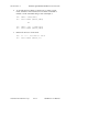
Purpose of Board Functions..................................................3-9
Multiboard Capability.............................................................3-9
IBFIND (bdname,bd)............................................................ 3-10
IBCMD (bd,buf,cnt) and..................................................... 3-10
IBRD (bd,buf,cnt) and ......................................................... 3-10
IBWRT (bd,buf,cnt) and..................................................... 3-12
IBSTOP (bd)............................................................................. 3-12
IBWAIT (bd,mask)................................................................ 3-12
IBTMO (bd,v).......................................................................... 3-12
IBONL (bd,v)........................................................................... 3-12
IBSIC (bd)................................................................................. 3-12
IBSRE (bd,v)............................................................................ 3-13
IBGTS (bd,v)............................................................................ 3-13
IBCAC (bd,v)........................................................................... 3-13
IBRPP (bd,buf)........................................................................ 3-13
IBPPC (bd,v)............................................................................ 3-13
More About Device and Board Functions .................................... 3-14
Group V......................................................................................................... 3-15
IBRSV (bd,v)........................................................................... 3-15
IBLOC (bd)............................................................................... 3-15
IBPPC (bd,v)............................................................................ 3-16
IBIST (bd,v).............................................................................. 3-16
IBWAIT (bd,mask)................................................................ 3-16
©National Instruments Corp.
xi
GPIB-PC User Manual
Contents
Group VI........................................................................................................ 3-17
IBEOT (bd,v)............................................................................ 3-17
IBEOS (bd,v)............................................................................ 3-18
IBBNA (bd,"GPIBn")........................................................... 3-18
IBDMA (bd,v).......................................................................... 3-18
IBPAD (bd,v) ........................................................................... 3-18
IBSAD (bd,v) ........................................................................... 3-18
IBRSC (bd,v) ........................................................................... 3-18
IBTMO (bd,v).......................................................................... 3-18
Section Four - GPIB-PC
Functions — Overview ................................................................................. 4-1
General Programming Information ................................................... 4-1
Status Word................................................................................................. 4-2
Error Codes.................................................................................................. 4-6
Count Variable......................................................................................... 4-11
Read and Write Termination............................................................ 4-11
Device Function Calls......................................................................... 4-12
Automatic Serial Polling.................................................................... 4-13
Section Four A - BASICA/QuickBASIC
GPIB-PC Function Calls ......................................................................... 4A-1
BASICA Files .......................................................................................... 4A-2
QuickBASIC Files................................................................................. 4A-2
Programming Preparations for BASICA.................... 4A-3
Programming Preparations for QuickBASIC ........... 4A-4
BASICA/QuickBASIC GPIB-PC I/O Functions ...................... 4A-5
BASICA/QuickBASIC "ON SRQ" Capability.......................... 4A-6
New GPIB-PC Functions ..................................................................4A-12
GPIB-PC Function Descriptions....................................................4A-15
IBBNA .........................................................................................................................4A-16
IBCAC.........................................................................................................................4A-17
IBCLR..........................................................................................................................4A-19
IBCMD........................................................................................................................4A-20
IBCMDA.....................................................................................................................4A-23
IBDMA........................................................................................................................4A-25
IBEOS..........................................................................................................................4A-26
IBEOT..........................................................................................................................4A-30
IBFIND ........................................................................................................................4A-32
IBGTS..........................................................................................................................4A-34
IBIST............................................................................................................................4A-36
IBLOC..........................................................................................................................4A-38
IBONL..........................................................................................................................4A-40
IBPAD..........................................................................................................................4A-42
GPIB-PC User Manual
xii
©National Instruments Corp.
Contents
IBPCT..........................................................................................................................4A-44
IBPPC ..........................................................................................................................4A-45
IBRD............................................................................................................................. 4A-47
IBRDA ........................................................................................................................ 4A-50
IBRDF..........................................................................................................................4A-54
IBRDI...........................................................................................................................4A-57
IBRDIA........................................................................................................................4A-60
IBRPP ..........................................................................................................................4A-64
IBRSC.......................................................................................................................... 4A-66
IBRSP ..........................................................................................................................4A-68
IBRSV..........................................................................................................................4A-70
IBSAD..........................................................................................................................4A-71
IBSIC............................................................................................................................4A-73
IBSRE..........................................................................................................................4A-74
IBSTOP .......................................................................................................................4A-76
IBTMO......................................................................................................................... 4A-78
IBTRAP....................................................................................................................... 4A-81
IBTRG..........................................................................................................................4A-83
IBWAIT.......................................................................................................................4A-84
IBWRT........................................................................................................................4A-87
IBWRTA..................................................................................................................... 4A-90
IBWRTF.....................................................................................................................4A-93
IBWRTI....................................................................................................................... 4A-95
IBWRTIA ..................................................................................................................4A-99
BASICA/QuickBASIC GPIB
Programming Examples...................................................................4A-103
BASICA Example Program - Device......................4A-105
BASICA Example Program - Board........................4A-108
QuickBASIC Example Program - Device.............4A-111
QuickBASIC Example Program - Board ...............4A-114
Section Five - IBIC .............................................................................................. 5-1
Running IBIC.................................................................................................5-2
Using HELP..................................................................................5-3
Using IBFIND..............................................................................5-3
Using IBWRT..............................................................................5-4
Using IBRD.................................................................................. 5-4
How to Exit IBIC.......................................................................5-5
Important Programming Note...............................................5-5
Using SET..................................................................................... 5-6
IBIC Functions and Syntax.....................................................................5-7
Other IBIC Functions and Syntax........................................................5-8
Status Word................................................................................................. 5-10
Error Code.................................................................................................... 5-11
©National Instruments Corp.
xiii
GPIB-PC User Manual
Contents
Byte Count................................................................................................... 5-12
Auxiliary Functions................................................................................. 5-12
SET (Select Device or Board)......................................... 5-13
HELP (Display Help Information).................................. 5-13
! (Repeat Previous Function)........................................... 5-14
- (Turn OFF Display)............................................................ 5-14
+ (Turn ON Display)............................................................. 5-15
n* (Repeat Function n Times)......................................... 5-16
$ (Execute Indirect File).................................................... 5-17
PRINT (Display the ASCII String)................................ 5-18
E or Q (exit or quit)............................................................... 5-18
IBIC Sample Programs.......................................................................... 5-19
Device Function Calls......................................................... 5-19
Board Function Calls............................................................ 5-22
Section Six - Applications Monitor .......................................................6-1
Installing the Applications Monitor....................................................6-2
IBTRAP..........................................................................................6-2
Applications Monitor Options................................................................6-5
Main Commands..........................................................................................6-6
Session Summary Screen........................................................................6-7
Configuring the Trap Mask .....................................................................6-7
Configuring the Monitor Mode..............................................................6-7
Hiding and Showing the Monitor .......................................6-8
Appendix A - Multiline Interface Messages .................................A-1
Multiline Interface Messages................................................................A-2
Interface Message Reference List.......................................................A-4
Appendix B - Common Errors
and Their Solutions.............................................................................................B-1
EDVR(0)..........................................................................................................B-1
ECIC(1)............................................................................................................B-1
ENOL(2).......................................................................................................... B-2
EADR(3)..........................................................................................................B-3
EARG(4)..........................................................................................................B-3
ESAC(5).......................................................................................................... B-4
EABO(6)..........................................................................................................B-4
ENEB(7).......................................................................................................... B-5
EOIP(10)..........................................................................................................B-5
ECAP(11)........................................................................................................B-5
EFSO(12)........................................................................................................ B-5
EBUS(14)........................................................................................................B-6
ESTB(15)........................................................................................................ B-6
GPIB-PC User Manual
xiv
©National Instruments Corp.
Contents
ESRQ(16)........................................................................................................B-6
Other Error Conditions...............................................................................B-7
Appendix C - Differences Between
Software Revisions...............................................................................................C-1
Revision B and Revision C....................................................................C-1
Interrupts........................................................................................ C-1
Startup Program.......................................................................... C-1
Configuration Program............................................................C-1
Interface Bus Interactive Control Program (IBIC) ....C-1
New Functions............................................................................C-2
Modified Functions...................................................................C-2
Language Interfaces.................................................................C-2
General........................................................................................... C-2
Revision C and Revision D....................................................................C-2
Device Functions.......................................................................C-2
Non-Interrupt Mode...................................................................C-2
Asynchronous I/O.......................................................................C-3
DMA on the GPIB-PCIII ........................................................C-3
Local Lockout.............................................................................C-3
SRQI Status Bit..........................................................................C-3
ATN and/or TIMO.....................................................................C-3
DCAS and DTAS Status Bits ..............................................C-3
Printer Support............................................................................C-3
Appendix D - Using your Printer
with the GPIB-PC ............................................................................................... D-1
Installation...................................................................................................... D-1
Appendix E - Application Notes..............................................................E-1
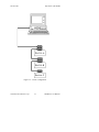
Application Note 1 - Computer to Computer
Data Transfer................................................................................................. E-1
Step 1. Configure the Computers......................................E-1
Step 2. Establish Communication ....................................E-1
Step 3. Transfer Data..............................................................E-2
Appendix F - Customer Communication .......................................F-1
Glossary.........................................................................................................................G-1
Index.................................................................................................................................I-1
©National Instruments Corp.
xv
GPIB-PC User Manual
Illustrations
List of Figures
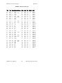
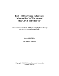
Figure 1.1 - GPIB Connector and the Signal Assignment .........................1-6
Figure 1.2 - Linear Configuration .......................................................................... 1-7
Figure 1.3 - Star Configuration ...............................................................................1-8
Figure 3.1 - Multiboard GPIB System............................................................... 3-11
Figure 6.1 - Applications Monitor Popup Screen...........................................6-1
List of Tables
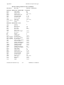
Table 2.1 - Timeout Settings................................................................................. 2-13
Table 2.2 - Functions that Alter Default Characteristics .........................2-17
Table 4.1 - Status Word Layout............................................................................. 4-2
Table 4.2 - GPIB Error Codes..................................................................................4-6
Table
Table
Table
Table
4A.1 - BASICA GPIB-PC Functions ..................................................4A-7
4A.2 - QuickBASIC GPIB-PC Calls...................................................4A-8
4A.3 - QuickBASIC GPIB-PC Calls.................................................4A-10
4A.4 - QuickBASIC Version 4.0 GPIB-PC Functions..............4A-14
Table 5.1 - Syntax of GPIB Functions in IBIC............................................... 5-8
Table 5.2 - Status Word Layout........................................................................... 5-11
Table 5.3 - Auxiliary Functions that IBIC Supports...................................5-12
©National Instruments Corp.
xvii
GPIB-PC User Manual
Section One - Operation of the GPIB
Communication between interconnected devices is achieved by passing
messages through the interface system.
Types of Messages
The GPIB carries two types of messages — device-dependent messages
and interface messages.
• Device-dependent messages, often called data or data messages,
contain device-specific information such as programming
instructions, measurement results, machine status, and data files.
• Interface messages manage the bus itself. They are usually
called commands or command messages. Interface messages
perform such functions as initializing the bus, addressing and
unaddressing devices, and setting device modes for remote or
local programming.
The term command as used here should not be confused with some
device instructions which can also be called commands. Such devicespecific instructions are actually data messages.
Talkers, Listeners, and Controllers
A Talker sends data messages to one or more Listeners. The Controller
manages the flow of information on the GPIB by sending commands to
all devices.
Devices can be Listeners, Talkers, and/or Controllers. A digital
voltmeter, for example, is a Talker and may be a Listener as well.
The GPIB is a bus like an ordinary computer bus except that the
computer has its circuit cards interconnected via a backplane bus
whereas the GPIB has standalone devices interconnected via a cable
bus.
The role of the GPIB Controller can also be compared to the role of the
computer's CPU, but a better analogy is to the switching center of a city
telephone system.
©National Instruments Corp.
1-1
GPIB-PC User Manual
Operation of the GPIB
Section One
The switching center (Controller) monitors the communications network
(GPIB). When the Controller notices that a party (device) wants to
make a call (send a data message), it connects the caller (Talker) to
the receiver (Listener).
The Controller usually addresses a Talker and a Listener before the
Talker can send its message to the Listener. After the message is
transmitted, the Controller usually unaddresses both devices.
Some bus configurations do not require a Controller. For example, one
device may always be a Talker (called a Talk-only device) and there
may be one or more Listen-only devices.
A Controller is necessary when the active or addressed Talker or
Listener must be changed. The Controller function is usually handled by
a computer.
With the GPIB-PC interface board and its software, your personal
computer plays all three roles:
•
Controller - to manage the GPIB,
•
Talker - to send data, and
•
Listener - to receive data.
The Controller-In-Charge and System Controller
Although there can be multiple Controllers on the GPIB, only one
Controller at a time is active, or Controller-In-Charge (CIC). Active
control can be passed from the current CIC to an idle Controller. Only
one device on the bus, the System Controller, can make itself the CIC.
The GPIB-PC is usually the System Controller.
GPIB-PC User Manual
1-2
©National Instruments Corp.
Section One
Operation of the GPIB
GPIB Signals and Lines
The interface system consists of 16 signal lines and 8 ground return or
shield drain lines.
The 16 signal lines are divided into the following three groups:
•
8 data lines,
•
3 handshake lines, and
•
5 interface management lines.
Data Lines
The eight data lines, DIO1 through DIO8, carry both data and command
messages. All commands and most data use the 7-bit ASCII or ISO
code set, in which case the 8th bit, DIO8, is unused or used for parity.
Handshake Lines
Three lines asynchronously control the transfer of message bytes
between devices:
•
NRFD,
•
NDAC, and
•
DAV.
The process is called a three-wire interlocked handshake and it
guarantees that message bytes on the data lines are sent and received
without transmission error.
NRFD (not ready for data)
NRFD indicates when a device is ready or not ready to receive a
message byte. The line is driven by all devices when receiving
commands and by Listeners when receiving data messages.
©National Instruments Corp.
1-3
GPIB-PC User Manual
Operation of the GPIB
Section One
NDAC (not data accepted)
NDAC indicates when a device has or has not accepted a message byte.
The line is driven by all devices when receiving commands and by
Listeners when receiving data messages.
DAV (data valid)
DAV tells when the signals on the data lines are stable (valid) and can
be accepted safely by devices. The Controller drives DAV lines when
sending commands and the Talker drives DAV lines when sending data
messages.
Interface Management Lines
Five lines are used to manage the flow of information across the
interface:
•
ATN,
•
IFC,
•
REN,
•
SRQ, and
•
EOI.
ATN (attention)
The Controller drives ATN true when it uses the data lines to send
commands and false when it allows a Talker to send data messages.
IFC (interface clear)
The System Controller drives the IFC line to initialize the bus and
become CIC.
REN (remote enable)
The System Controller drives the REN line, which is used to place
devices in remote or local program mode.
GPIB-PC User Manual
1-4
©National Instruments Corp.
Section One
Operation of the GPIB
SRQ (service request)
Any device can drive the SRQ line to asynchronously request service
from the Controller.
EOI (end or identify)
The EOI line has two purposes. The Talker uses the EOI line to mark
the end of a message string. The Controller uses the EOI line to tell
devices to identify their response in a parallel poll.
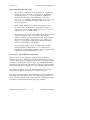
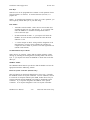
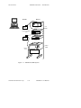
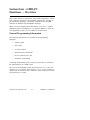
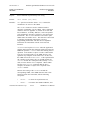
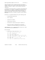
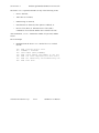
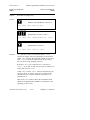
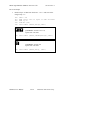
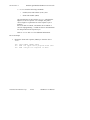
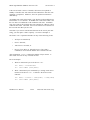
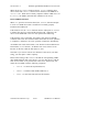
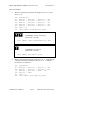
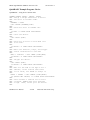
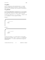
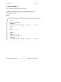
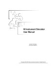
Physical and Electrical Characteristics
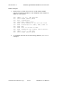
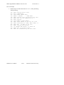
Devices are usually connected with a cable assembly consisting of a
shielded 24-conductor cable with both a plug and receptacle connector
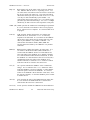
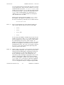
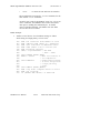
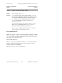
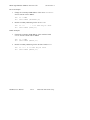
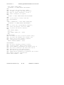
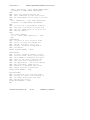
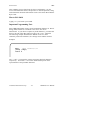
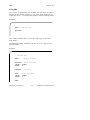
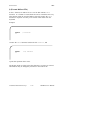
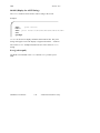
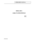
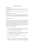
at each end. This design allows devices to be linked in either a linear
or a star configuration, or a combination of the two. See Figures 1.1,
1.2, and 1.3.
The standard connector is the Amphenol or Cinch Series 57
MICRORIBBON or AMP CHAMP type. An adapter cable using nonstandard cable and/or connector is used for special interconnect
applications.
The GPIB uses negative logic with standard TTL logic level. When
DAV is true, for example, it is a TTL low-level ( ≤ 0.8V), and when
DAV is false, it is a TTL high-level ( ≥ 2.0V).
©National Instruments Corp.
1-5
GPIB-PC User Manual
Operation of the GPIB
DIO1
DIO2
DIO3
DIO4
EOI
DAV
NRFD
NDAC
IFC
SRQ
ATN
SHIELD
Section One
1
2
3
4
5
6
7
8
9
10
11
12
DIO5
DIO6
DIO7
DIO8
REN
GND (TW PAIR W/DAV)
GND (TW PAIR W/NRFD)
GND (TW PAIR W/NDAC)
GND (TW PAIR W/IFC)
GND (TW PAIR W/SRQ)
GND (TW PAIR W/ATN)
SIGNAL GROUND
13
14
15
16
17
18
19
20
21
22
23
24
Figure 1.1 - GPIB Connector and the Signal Assignment
GPIB-PC User Manual
1-6
©National Instruments Corp.
Section One
Operation of the GPIB
Figure 1.2 - Linear Configuration
©National Instruments Corp.
1-7
GPIB-PC User Manual
Operation of the GPIB
Section One
Figure 1.3 - Star Configuration
GPIB-PC User Manual
1-8
©National Instruments Corp.
Section One
Operation of the GPIB
Configuration Requirements
To achieve the high data transfer rate that the GPIB was designed for,
the physical distance between devices and the number of devices on the
bus are limited.
The following restrictions are typical.
• A maximum separation of four meters between any two devices
and an average separation of two meters over the entire bus.
• A maximum total cable length of 20 meters.
• No more than 15 devices connected to each bus, with at least
two-thirds powered on.
Bus extenders are available from National Instruments and other
manufacturers for use when these limits must be exceeded.
Related Documents
For more information on topics covered in this section consult the
following related documents.
• IEEE Std. 488-1978, IEEE Standard Digital Interface for
Programmable Instrumentation.
• GPIB-PC Technical Reference Manual.
©National Instruments Corp.
1-9
GPIB-PC User Manual
Section Two - Installation and
Configuration
The procedures for installing your GPIB-PC depend on your model of
board and your make of computer. A supplement to Section Two
contains information about your interface board. Section Two A, for
example, contains information about the model GPIB-PCIIA for the IBM
PC and compatible computers.
Installing the Hardware
To install your hardware, follow the instructions in the Section Two
supplement for your interface board.
If you change the default settings of any switches, make a note of the
new values so that you can refer to them when you configure your
software.
Install the hardware before continuing.
The GPIB-PC Software Package
Before you install your software, you might wish to review the files on
your GPIB-PC distribution diskette to gain an understanding of what
they are.
The following files are the main files of the GPIB-PC software:
•
GPIB.COM - is a device handler file that is loaded at system
start-up by the DOS operating system. Handler is a term used
by National Instruments to refer to a loadable device driver.
•
BIB.M - is a language interface file that provides an
application program access to the GPIB-PC handler. BIB.M is
intended for use with programs written in BASICA.
•
QBIB*.OBJ - is a language interface file that provides an
application program access to the GPIB-PC handler.
QBIB*.OBJ is intended for use with programs written in
QuickBASIC.
©National Instruments Corp.
2-1
GPIB-PC User Manual
Installation and Configuration
Section Two
•
DECL.BAS - is a declaration file that contains code to be
placed at the beginning of the BASICA and QuickBASIC
application programs.
•
QBDECL.BAS - is a declaration file that contains code to be
placed at the beginning of the QuickBASIC application
programs.
Additional Programs and Files
The following additional programs and files include installation, test,
and example programs:
•
APPMON.COM - is the applications monitor program. It is a
resident program that is useful in debugging sequences of GPIB
calls from within your application. The applications monitor
provides the capability to trap on return from GPIB driver calls,
allowing you to inspect function arguments, buffers, return
values, GPIB global variables, and other pertinent data.
•
IBTRAP.EXE - is a program that configures the applications
monitor.
•
IBSTART.BAT - is a batch file used for installation and startup. It is a multipurpose program that performs the software
installation. It copies files, modifies CONFIG.SYS (the DOS
system configuration file) using MKCFG.EXE, and tests the
hardware using IBDIAG.EXE.
•
IBDIAG.EXE - is a program that tests the hardware installation
before the GPIB software is configured and installed. After the
handler is installed, IBTEST.BAT confirms that both the
software and hardware are installed and functioning properly.
The test is executed in two parts using IBTSTA.EXE and
IBTSTB.EXE.
•
IBCONF.EXE - is a software configuration program that allows
you to change the software parameters and other data used by
the handler.
•
IBIC.EXE - is an interactive control program that allows you
to execute the handler functions interactively from your
keyboard. It helps you to learn the functions, to program your
instrument or other GPIB device, and to develop your
application program.
GPIB-PC User Manual
2-2
©National Instruments Corp.
Section Two
•
Installation and Configuration
DBSAMP.BAS, BBSAMP.BAS, DQBSAMP, BIBSAMP, and
DIBSAMP - are example programs for BASICA, QuickBASIC,
and IBIC. The BASICA and QuickBASIC supplement of the
manual, Section Four A, contains additional examples.
Installing the Software
The term boot disk refers to the hard disk or floppy disk that contains
DOS and that is read by your computer when it is booted. The term
boot refers to the action of loading DOS into your system from your boot
disk, either when power is applied or when the warm boot keys are
pressed.
Step 1 - Preparation
Your first step is determined by whether you wish to boot from a floppy
disk or a hard disk. Perform the step that applies to your system.
Booting from a Floppy Disk
If you boot DOS from a floppy diskette, you need a boot disk with
enough free space to hold a copy of the GPIB-PC software contained on
the distribution diskette.
Insert the boot diskette into the first drive (usually named A:) and the
distribution diskette into the second drive (B:). Boot your system if you
have not already done so.
Booting from a Hard Disk
If you boot DOS from a hard disk, you need a personal computer with
one floppy drive. The hard disk must have enough free space to hold a
copy of the GPIB-PC software contained on the distribution diskette.
Boot your system. Then, insert the distribution diskette into the floppy
drive.
©National Instruments Corp.
2-3
GPIB-PC User Manual
Installation and Configuration
Section Two
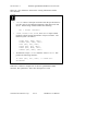
Step 2 - Run IBSTART
Run IBSTART from the distribution diskette by switching to the drive
containing the distribution diskette and entering:
ibstart x:
replacing x with the letter of the boot drive. For example, if the
distribution diskette is in drive B and you have booted from drive A,
enter:
b:
to switch to drive B. Next, enter:
ibstart a:
to run IBSTART.
IBSTART first creates a directory called GPIB-PC on the boot diskette,
and copies the GPIB software to that directory. If the insufficient
disk space message appears, abort the IBSTART program by
pressing the control key while you enter:
c
Increase the free space in your boot area and run IBSTART again.
Next, IBSTART creates or modifies the DOS system configuration file
CONFIG.SYS to contain the line:
DEVICE=GPIB.COM
By reading this file at boot time, DOS installs new device drivers and
handlers.
Next, IBSTART switches to the boot drive to run the hardware
diagnostic program, IBDIAG.
GPIB-PC User Manual
2-4
©National Instruments Corp.
Section Two
Installation and Configuration
Finally, IBSTART advises you to complete the following actions:
•
Run IBCONF if you must reconfigure the software;
•
Reboot your system to load the handler into DOS; and
•
Run IBTEST to test the installation of the software.
Step 3 - Run IBCONF (optional)
The pamphlet Getting Started with your GPIB-PC that comes with your
interface board explains when you must run IBCONF to reconfigure the
software. You may also run IBCONF to examine how the software is
configured.
See More About IBCONF later in this section for information on how to
run IBCONF and on the configurable software parameters.
NOTE: You must run IBCONF if you have a PCIIA, or wish to change
defaults.
Step 4 - Reboot
Reboot your computer from the drive you specified when you ran
IBSTART so that DOS will load the GPIB-PC handler.
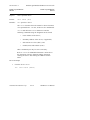
Step 5 - Test Software Installation
Run IBTEST from the directory GPIB-PC in your boot area by entering:
cd gpib-pc
ibtest
IBTEST tests whether the handler is installed and functioning with the
GPIB-PC.
©National Instruments Corp.
2-5
GPIB-PC User Manual
Installation and Configuration
Section Two
If errors occur, check the following:
•
Did you read Getting Started with your GPIB-PC and make any
required changes? If not, do so now.
•
Did you change hardware switch settings on your GPIB-PC
board? If so, run IBCONF and accurately input the new settings
for the board.
•
Are the GPIB.COM and CONFIG.SYS files installed in the root
directory of your boot drive? If not, check and repeat the
installation instructions.
•
Did you reboot your system before you ran IBTEST? If not, do
so now.
If you have performed these steps and IBTEST still fails, carefully note
all error information and call National Instruments.
If no errors occur, proceed to the end of this section to learn how to use
the software and to develop your application program.
More About IBCONF
IBCONF is a screen-oriented, interactive program that is included on the
distribution diskette of the GPIB-PC package.
You use IBCONF to edit the description in the handler of characteristics
of the devices and boards in the system. Running IBCONF to place this
information directly in the handler eliminates the need to restate it
inside each application program.
IBCONF passes two groups of features to the handler. The first group
consists of the characteristics of the instruments or devices attached to
your GPIB-PC. The second group consists of the characteristics of each
GPIB-PC installed in the computer.
GPIB-PC User Manual
2-6
©National Instruments Corp.
Section Two
Installation and Configuration
Characteristics of the Instruments
Each instrument used with the GPIB-PC has the following
characteristics:
•
A symbolic name of each device on the GPIB (such as DEV5 or
PS5010).
•
A GPIB-PC access board for each device (e.g., GPIB0). The
access board is discussed in Device Map Concepts and Terms
later in this section.
•
A primary and, if used, secondary address for each device.
•
A time limit that is to be imposed when executing certain
functions. This is to ensure that accessing a powered-off device
does not hang up the GPIB indefinitely.
•
A way to terminate I/O transmissions to and from the device.
Some devices require or append an end-of-string character, such
as the ASCII line feed character, to data strings. Others use the
GPIB END message, which is sent or received via the EOI
signal line. Still others use both. Some terminate messages
only when a predetermined number of bytes are sent or
received.
Characteristics of each GPIB-PC
Each GPIB-PC has the following characteristics:
•
A symbolic name (such as GPIB0 and GPIB1).
•
A computer I/O or port address.
•
The capability to be designated as the System Controller of the
devices on its bus.
•
A time limit that is imposed when executing certain functions.
•
A way to terminate I/O transmissions to and from the board
when executing board calls, i.e., by an end-of-string character,
an END message, and/or a byte count.
•
An interrupt level that the board uses.
©National Instruments Corp.
2-7
GPIB-PC User Manual
Installation and Configuration
Section Two
•
What DMA channel, if any, the board uses.
•
Whether it uses high-speed or normal timing when transmitting
data to a device. With normal timing, there is a delay of at
least 2 µsec after the data is placed on the GPIB before the
Data Valid (DAV) line is asserted. With high-speed timing,
this delay is decreased to about 500 nsec.
•
The Internal Clock Frequency for a PC-IIA. This is the value of
the internal PC bus clock.
Default Configurations
Just as the hardware has factory default settings for switches and
jumpers, the software also has factory default configurations. For
example, the default device names of the 16 GPIB devices are DEV1
through DEV16, but you might wish to assign more descriptive names to
each device, such as METER for a digital multimeter.
You can also use IBCONF to look at the current default settings in the
handler file.
If you do not make changes using IBCONF, the default characteristics of
the software remain in effect.
Primary Default Characteristics
The following are the primary default characteristics of the handler.
•
There are 16 active devices with symbolic names DEV1 through
DEV16.
•
GPIB addresses of these devices are the same as the device
number; for example, DEV1 is at address 1.
•
The 16 devices are assigned to GPIB0 as their access board.
GPIB0 is the symbolic name of the first GPIB-PC board in your
system. If you have an additional GPIB-PC in your system, its
symbolic name is GPIB1.
•
Each GPIB-PC is System Controller of its independent bus and
has a GPIB address of 0.
•
The END message is sent with the last byte of each data
message to a device. Each data message that is read from a
GPIB-PC User Manual
2-8
©National Instruments Corp.
Section Two
Installation and Configuration
device is automatically terminated when END is received. No
end-of-string character is recognized.
•
The time limit on I/O and wait function calls is approximately
10 seconds.
•
GPIB0 is a Model GPIB-PCII, is at base I/O address hex 02B8,
and uses DMA Channel 1 and TLC Interrupt Line 7.
•
You must run IBCONF if you are using a GPIB-PCIIA or if you
have changed the hardware switches/jumpers on any GPIB-PC
from the factory settings. Otherwise, it is unnecessary to run
IBCONF. Consult the appropriate supplement to Section Two
of the user manual to find the factory settings of your GPIB-PC
model.
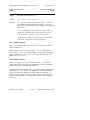
Running IBCONF
When you ran IBSTART, a copy of IBCONF.EXE was placed on your
boot drive.
To run IBCONF, go to the root directory of the boot drive and enter:
ibconf
If you have a color monitor, the configuration program will
automatically appear in color. If you have a color monitor but want the
configuration program to appear in monochrome, enter:
ibconf -m
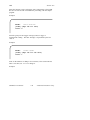
IBCONF scans the handler file, GPIB.COM, and reads its data structures
into memory. After you press a key, the program displays the Device
Map for board GPIB0.
©National Instruments Corp.
2-9
GPIB-PC User Manual
Installation and Configuration
Section Two
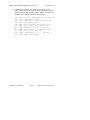
IBCONF makes changes to the GPIB.COM file, which should also be in
the root directory. If you want IBCONF to make changes to a different
copy of GPIB.COM such as GPIB2.COM, enter the path and name of
the GPIB.COM file you want modified:
ibconf c:\GPIB-PC\GPIB2.COM
This will have the effect of changing the parameters within the
GPIB2.COM file in the GPIB-PC subdirectory.
Modify only the copy of GPIB.COM created by IBSTART in your boot
directory. Never modify the master copy on the distribution diskette.
This would happen if you ran IBCONF from the distribution diskette and
if the distribution diskette were not write-protected.
Upper and Lower Levels of IBCONF
IBCONF operates at both an upper and a lower level. The upper level
consists of the Device Maps and gives an overview of the GPIB system
as defined within the handler being configured. The lower level consists
of screens that describe each individual board and device in the system.
Upper Level - Device Map for Board GPIBx
This screen displays the names of all devices defined in the handler file,
and indicates which devices, if any, are accessed through the interface
board GPIBx. At this level, you may:
•
Rename a device;
•
Disconnect a device from its assigned GPIB-PC access board or
connect (reassign) it to a different access board; or
•
Proceed to the lower level to edit or examine the
characteristics of a particular board or device.
Instructions are given on the screen for selecting the individual devices
and for changing from one device map to another, for example, from the
map for GPIB0 to that for GPIB1.
GPIB-PC User Manual
2-10
©National Instruments Corp.
Section Two
Installation and Configuration
Device Map Concepts and Terms
•
Device Name - contains up to seven characters. The rules for
naming devices are the same as DOS rules for naming files,
except that suffixes (.xxx) are not allowed. DOS treats
uppercase and lowercase letters identically. The string
"PLOTTER" is treated the same as the string "plotter". For
this reason, the configuration program maps all lowercase
letters to uppercase.
Device names must not be given the same names as files,
directories, and/or subdirectories. If you name a device PLTR
and your file system already contains the file PLTR.DAT or a
subdirectory PLTR, a conflict results.
•
Access Board - all devices on the GPIB require an access board
within the computer. The access board is the GPIB-PC
interface board that provides the hardware link to the computer.
The access board name is of the form GPIBx, where x is a
digit 0 or 1 representing the appropriate GPIB board number.
The access board name is not alterable.
The string representing a device or board name is the first
variable argument of the function IBFIND called at the
beginning of your application program. Refer to Sections Three
and Four for detailed explanations of IBFIND.
Lower Level - Device/Board Characteristics
The lower level screens display the currently defined values for
characteristics such as addressing and timeout information of a device
or board. Instructions are available on the screen for selecting a specific
field and for modifying the current settings. The configuration settings
selected for each device and each board are a means of customizing the
communications and other options to be used with that board or device.
The settings for devices specify the characteristics to be used by the
access board for that device when device functions are used.
The settings for boards specify the characteristics to be used with each
board when board functions are used. In the following explanations of
device and board characteristics, notice that some characteristics apply
to both devices and boards and some apply only to boards.
©National Instruments Corp.
2-11
GPIB-PC User Manual
Installation and Configuration
Section Two
Device and Board Characteristics
Primary GPIB Address
Each device and board must be assigned a unique primary address in the
range hex 00 to hex 1E. A listen address is formed by adding hex 20 to
the primary address; the talk address is formed by adding hex 40 to the
primary address. Consequently, a primary address of hex 10 corresponds
to a listen address of hex 30 and a talk address of hex 50. The GPIB
primary address of any device is set within that device, either with
hardware switches, or, in some cases, a software program. This address
and the address listed in IBCONF must be the same. Refer to the
device-specific documentation provided with your instrument for
instructions about that device's address. The primary GPIB address of
all GPIB-PC boards is 0, unless changed by IBCONF. There are no
hardware switches on the GPIB-PC to select the GPIB address.
Secondary GPIB Address
Any device or board using extended addressing must be assigned a
secondary address in the range hex 60 to hex 7E, or the option NONE
may be selected to disable secondary addressing. As with primary
addressing, the secondary GPIB address of any device is set within that
device, either with hardware switches, or, in some cases, a software
program. This address and the address listed in IBCONF must be the
same. Refer to the device documentation for instructions. Secondary
addressing is disabled for all devices and boards unless changed by
IBCONF.
Timeout Settings
The timeout value is the approximate length of time that may elapse
before I/O functions such as IBRD, IBWRT, and IBCMD complete. It is
also the length of time that the IBWAIT function waits for an event
before returning if the TIMO bit is set. Consequently, a wait for the
SRQ line to be asserted will terminate after the time limit is reached if
both the SRQI and TIMO bits are set in the mask passed to IBWAIT,
and no SRQ signal is detected. Refer to the IBWAIT function
description in Sections Three and Four for more information.
GPIB-PC User Manual
2-12
©National Instruments Corp.
Section Two
Installation and Configuration
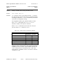
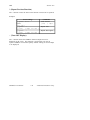
This field is set to a code mnemonic which specifies the time limit as
follows:
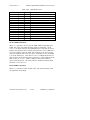
Table 2.1 - Timeout Settings
Code
TNONE
T10µsec
T30µsec
T100µsec
T300µsec
T1msec
T3msec
T10msec
T30msec
T100msec
T300
T1sec
T3sec
T10sec
T30sec
T100sec
T300sec
T1000sec
Actual Value
0
1
2
3
4
5
6
7
8
9
10
11
12
13
14
15
16
17
Minimum Timeout
disabled
10 µsec
30 µsec
100 µsec
300 µsec
1 msec
3 msec
10 msec
30 msec
100 msec
300 msec
1 sec
3 sec
10 sec
30 sec
100 sec
300 sec
1000 sec
NOTE: If you select TNONE, no limit will be in effect.
©National Instruments Corp.
2-13
GPIB-PC User Manual
Installation and Configuration
Section Two
EOS Byte
Some devices can be programmed to terminate a read operation when a
selected character is detected. A linefeed character (hex 0A) is a
popular one.
NOTE: To send the EOS character to a device in a write operation, you
must explicitly include that byte in your data string.
EOS Modes
•
Terminate a Read on EOS - Some devices send an EOS byte
signaling the last byte of a data message. A yes response will
cause the GPIB-PC to terminate read operations when it
receives the EOS byte.
•
Set EOI with EOS on Write - A yes response will cause the
GPIB-PC to assert the EOI (send END) line when the EOS
character is sent.
•
7- or 8-bit compare on EOS - Along with the designation of an
EOS character, you may specify whether all eight bits are
compared to detect EOS, or just the seven least significant bits
(ASCII or ISO format).
Set EOI with last byte of Write
Some devices, as Listeners, require that the Talker terminate a data
message by asserting the EOI signal line (sending END) with the last
byte. A yes response will cause the GPIB-PC to assert EOI on the last
data byte.
GPIB-PC Model
The GPIB-PC Model must be specified so that the handler will use the
appropriate hardware addressing scheme.
Board is System Controller (Boards Only)
This field appears on the board characteristics screen only. Generally,
the GPIB-PC will be the System Controller. In some situations, such as
in a network of computers linked by the GPIB, another device may be
System Controller and the GPIB-PC will NOT be designated System
Controller. A yes response designates the GPIB-PC to be System
Controller. A no response designates it not to be System Controller.
GPIB-PC User Manual
2-14
©National Instruments Corp.
Section Two
Installation and Configuration
Local Lockout on all Devices (Boards Only)
It is desirable to place many devices in the local lockout state while
they are being remotely accessed. If yes is selected, the access board
will place all of its devices in local lockout state while accessing them.
Disable Auto Serial Polling (Boards Only)
This option allows you to disable automatic serial polls if this feature is
incompatible with certain devices on the bus. While this feature is on,
the handler conducts serial polls of the devices and stores positive
responses whenever the GPIB Service request (SRQ) line is asserted.
Refer to Automatic Serial Polling of Section Four for further information.
Normally, this feature will not conflict with devices that conform to the
IEEE-488 specification.
High-Speed Timing (Boards Only)
Some devices are unable to read data messages at high-speed (Tristate) timing. If your GPIB system has slower devices, you may want to
select a longer data setting time by selecting no for this field.
Interrupt Jumper Setting (Boards Only)
This field must be set to the same value as the interrupt level jumper
setting on the GPIB-PC board itself. For most personal computers, this
jumper setting reflects the actual interrupt level selected. Any
exception is explained in the Getting Started with your GPIB-PC
pamphlet that comes with the interface board. Any valid interrupt level
may be selected, provided the level does not conflict with other
equipment.
Base I/O Address (Boards Only)
The GPIB-PC may be assigned any one of the legal base I/O or port
addresses as described in the appropriate supplement to this section.
The value entered must match the hardware setting selected during
hardware configuration. If it does not match, the handler cannot
communicate with the GPIB-PC.
©National Instruments Corp.
2-15
GPIB-PC User Manual
Installation and Configuration
Section Two
DMA Channel (Boards Only)
This field appears only on computers supporting DMA capability. The
GPIB-PC may use any of the three DMA channels, 1, 2, or 3, provided
that another device is not already using that channel. If a DMA channel
is not available, programmed I/O can be enabled by selecting NONE.
Internal Clock Frequency (Boards Only)
For the GPIB-PCII, this value is equal to the frequency of the PC bus
signal OSC divided by 2 and rounded up. Since OSC is fixed at 14.14
MHz for all IBM PCs and compatibles, this field is always set to 8.
For the GPIB-PCIIA, this value is equal to the frequency of the PC bus
signal CLK and rounded up. Since the signal CLK varies according to
the machine, this field varies as well. Typical examples are:
Machine
PCII ICF value
IBM PC, XT, and compatibles
8
IBM XT (new)
8
IBM AT and compatibles
8
Compaq Deskpro
8
Compaq Deskpro 286
8
Compaq Portable 286
8
PCIIA ICF value
5
8
6
5,8
6,8
6,8
Notice that on some computers the CLK frequency depends on whether
the CPU is operated at normal or high-speed mode. If you want to
operate the GPIB-PC under both modes, either reconfigure the software
or use the higher value. If you are in doubt as to what value to enter,
use 8.
Exiting IBCONF
Once all changes have been made, you may exit IBCONF by typing the
function key indicated on the screen. The program will first ask if it
should save any changes before exiting. Typing a y response causes the
changes to be written to the file on disk. Before exiting, the program
will check for situations that may cause problems.
GPIB-PC User Manual
2-16
©National Instruments Corp.
Section Two
Installation and Configuration
Situations which are checked are as follows:
•
GPIB addressing conflict between a device and its access
board;
•
GPIB boards not present in the host machine at the specified
address; and
•
Timeouts disabled on a device or board.
If any of these situations is encountered, you will be notified and given
the option of re-entering or exiting IBCONF. To disable auto-checking,
call IBCONF -E.
After exiting, the system MUST be rebooted for the new values to take
effect.
Some functions may be called during the execution of an application
program to change some of the configured values temporarily. These
functions are shown in Table 2.2.
Table 2.2 - Functions that Alter Default Characteristics
Characteristic
Primary GPIB address
Secondary GPIB address
End-of-string (EOS) byte
7- or 8- bit compare on EOS
Set EOI with EOS on Write
Terminate a Read on EOS
Set EOI w/last byte of Write
Change board assignment
Enable or disable DMA
Change or disable time limit
Request/release system control
©National Instruments Corp.
2-17
Dynamically Changed by
IBPAD
IBSAD
IBEOS
IBEOS
IBEOS
IBEOS
IBEOT
IBBNA
IBDMA
IBTMO
IBRSC
GPIB-PC User Manual
Installation and Configuration
Section Two
Using Your GPIB-PC
Now that your software and hardware are installed, read Section Three
for an introduction to the functions available for the GPIB-PC. The
functions are described in the order that you will most likely use them.
Pay special attention to Group I, Group II, and Group III.
After reading about these functions, practice using them with your
programmable instrument or device in an interactive environment using
the IBIC program described in Section Five. IBIC allows you to
program your instrument interactively from the computer keyboard rather
than from an application program. This helps you understand how the
device and the handler work. It also familiarizes you with status
information that is returned by each function and that is also available
to your application program in the form of global variables.
While running IBIC, study the descriptions of each function given in
Section Four to fully understand the purpose and syntax of each
function.
Finally, referring to the appropriate language supplement of Section
Four, write your application program. Whenever possible, use IBIC to
test the sequence of the GPIB-PC function calls your application
program makes. Trying your function calls from IBIC is especially
helpful if your application program responds in an unexpected manner.
GPIB-PC User Manual
2-18
©National Instruments Corp.
Section Three - GPIB-PC
Functions — Introduction
This section introduces you to the GPIB-PC handler functions and their
capabilities. They are described in the order you will most likely use
them.
Application environments for which the functions are designed are
described. Short examples illustrate how the functions operate.
Introduction to the GPIB-PC Functions
The GPIB-PC functions are high-level and low-level functions that
communicate with and control devices on the GPIB. The functions are
divided into six groups, and each group is distinguished by the type of
applications it serves. The functions contained in the first three groups
are mostly high-level, while those of the last three are mostly low-level.
High-Level Functions
High-level functions are easy to learn and use. They automatically
execute sequences of commands that handle bus management
operations required to perform activities such as reading from and
writing to devices and polling them for status. These functions free you
from having to know the GPIB protocol or bus management details
involved. Most device functions (functions that specify a device) are
high-level functions.
Low-Level Functions
In contrast, low-level functions perform rudimentary or primitive
operations that require that you know something about GPIB protocol to
use them effectively. They are needed because high-level functions do
not always meet the requirements of applications. In such cases, lowlevel functions offer the flexibility you need to solve most of your
application problems. All board functions (functions that specify a
board) are low-level functions.
Calling Syntax
The calling syntax for GPIB-PC functions varies according to the
language used. In this section, a generic syntax is used to identify the
function and its arguments.
©National Instruments Corp.
3-1
GPIB-PC User Manual
GPIB-PC Functions — Introduction
Section Three
Group I
Group I functions may be the only functions you need for many of your
instrument control applications. Group I functions are as follows:
•
IBRD,
•
IBWRT, and
•
IBFIND.
They are suitable for your applications under the following conditions:
•
Communication is between the Controller (computer) and one
device at a time. Messages are not broadcast to several
devices at once, and devices do not talk to each other directly.
•
Devices do not require special services or operations, such as
polling or triggering, to send or receive data.
IBRD and IBWRT are high-level input/output (I/O) functions. IBFIND
is a start-up function that opens the device.
IBRD (bd,buf,cnt)
IBRD reads a specified number of bytes from a device and stores them
in memory. The device is automatically addressed before reading and
unaddressed afterward. If not done previously, the GPIB is initialized on
entering the function and the device is placed in remote programming
mode.
When programming in BASIC, IBRD performs string transfers. IBRDI
is available for binary transfers to an integer array.
IBWRT (bd,buf,cnt)
IBWRT writes a specified number of bytes from the memory buffer to a
device. The device is automatically addressed before writing and
unaddressed afterward. If not done previously, the GPIB is initialized on
entering the function, and the device is placed in remote programming
mode.
When programming in BASIC, IBWRT performs string transfers.
IBWRTI is available for binary transfers from an integer array.
GPIB-PC User Manual
3-2
©National Instruments Corp.
Section Three
GPIB-PC Functions — Introduction
IBFIND (bdname,bd)
IBFIND returns a unit descriptor associated with the name of the
device. When the software is installed, a description of each device is
placed in an internal reference table accessible by the handler. This
description includes the GPIB address, end-of-string (EOS) modes,
timeout selection, and a name for the device.
Group II
Group II functions offer additional high-level device services often
needed in common instrument control applications. Group II functions
are as follows:
•
IBRSP,
•
IBCLR,
•
IBTRG, and
•
IBLOC.
IBRSP (bd,spr)
IBRSP serially polls a device and returns its status response. The
response consists of a single byte in which the hex 40 bit is set if the
device is requesting service and asserting Service Request (SRQ).
Here are examples of a Tektronix 4041 BASIC SRQ handler call and
the corresponding IBRSP call. In this case, the device being polled is
the plotter and is at GPIB address 7:
POLL STATUS, ADDRESS; 7
CALL IBRSP (PLTR%,STATUS%)
In both cases, the plotter's status response is stored in the variable
STATUS.
Unless disabled during software configuration, any device function call
will automatically conduct serial polls if SRQ is asserted on GPIB. This
automatic serial polling is discussed in Section Four.
©National Instruments Corp.
3-3
GPIB-PC User Manual
GPIB-PC Functions — Introduction
Section Three
IBCLR (bd)
IBCLR clears the device by sending to it the Selected Device Clear
(SDC) and appropriate addressing commands.
Clearing the Device Versus Clearing the GPIB
There is a difference between clearing or initializing devices and
clearing or initializing the GPIB itself.
Clearing the Device
The Selected Device Clear (SDC) command that is sent by the IBCLR
function resets internal functions of the device, such as causing a digital
multimeter to change its function, range, and trigger mode back to
default settings.
Clearing the GPIB
The Interface Clear (IFC) command initializes the GPIB and the bus
interface circuits of all attached devices without affecting internal
functions. IFC is sent automatically when the first device function is
called.
A device function is a function that references a device such as the four
already described: IBRD, IBWRT, IBRSP, and IBCLR.
IBTRG (bd)
IBTRG triggers the device by sending to it the Group Execute Trigger
(GET) and appropriate addressing commands.
IBLOC (bd)
IBLOC places the device in local program mode by sending the Go To
Local (GTL) and appropriate addressing commands to the device.
Placing a Device in Remote Mode
The first device function call after power-on, in addition to sending the
IFC command as previously described, also places the device in remote
program mode by setting the GPIB Remote Enable (REN) line and
addressing the device to listen.
GPIB-PC User Manual
3-4
©National Instruments Corp.
Section Three
GPIB-PC Functions — Introduction
Placing a Device in Local Mode
Devices must usually be placed in remote program mode before they
can be programmed from the GPIB. This operation is done
automatically by the handler. The IBLOC function is then used when
that device must be returned to local program mode.
In addition, unless disabled using the configuration program (IBCONF),
the handler places devices in local lockout mode, which prevents you
from returning a device to local mode using the device's front-panel
control.
The seven previously described functions will be sufficient to meet your
application needs, in most cases. They are the most important functions
for you to learn.
Group III
The functions of Group III are more flexible for controlling and
communicating with devices. Group III functions are as follows:
•
IBRDA,
•
IBWRTA,
•
IBRDF,
•
IBWRTF,
•
IBWAIT,
•
IBSTOP,
•
IBTMO,
•
IBONL, and
•
IBPCT.
©National Instruments Corp.
3-5
GPIB-PC User Manual
GPIB-PC Functions — Introduction
Section Three
These functions are used under the following conditions:
•
Program execution must proceed in parallel with GPIB I/O –
often called asynchronous operation.
•
I/O is to or from a file rather than a memory buffer.
•
Controller-In-Charge authority must be transferred to another
GPIB device.
•
The timeout value must be changed.
•
The handler must be reinitialized with respect to certain
devices.
IBRDA (bd,buf,cnt) and
IBWRTA (bd,buf,cnt)
These functions are similar to IBRD and IBWRT except that the
operation is asynchronous. This means that the function returns after
starting the I/O operation without waiting for it to complete.
When programming in BASIC, IBRDA and IBWRTA perform string
transfers. IBRDIA and IBWRTIA are available for transfers to and from
an integer array.
IBRDF (bd,buf,cnt) and
IBWRTF (bd,buf,cnt)
These functions are similar to IBRD and IBWRT except that data is read
into a file.
IBWAIT (bd,mask)
IBWAIT waits for one or more events to occur. For the IBRDA and
IBWRTA functions, the event to wait for is the completion of the
operation.
IBSTOP (bd)
IBSTOP aborts any asynchronous operation associated with the device.
GPIB-PC User Manual
3-6
©National Instruments Corp.
Section Three
GPIB-PC Functions — Introduction
IBTMO (bd,v)
IBTMO changes the time limit in which operations with the device must
complete.
IBONL (bd,v)
IBONL re-initializes the device and cancels any asynchronous I/O in
progress. All reconfigurable software parameters, such as the time limit
just discussed, are reset to their power-on values. See the discussion of
software configuration in Section Two for further information on
reconfigurable software parameters.
The last function in this group allows the computer to pass control to
another device capable of being the Controller.
IBPCT (bd)
IBPCT passes Controller-In-Charge authority to the specified device by
sending the Take Control (TCT) commands and appropriate addressing
commands.
Most GPIB-compatible instruments or other types of devices can be
programmed using the high-level functions of Groups I, II, or III. Not all
devices, however, are completely compatible with the IEEE-488
specification, nor are the combinations of bus management and/or I/O
operations contained in the high-level functions suitable for all
applications.
Some operations, such as interprocessor networks and peripheral
sharing, require additional capabilities and flexibility in controlling the
GPIB. This is achieved, in part, with low-level functions that perform
single GPIB activities, each with a limited scope or objective. Powerful
and versatile routines can be developed using these functions. Groups
IV, V, and VI consist mostly of low-level functions.
©National Instruments Corp.
3-7
GPIB-PC User Manual
GPIB-PC Functions — Introduction
Section Three
Group IV
The functions described previously have been device functions; that is,
the bd argument referred to a device on the GPIB. This section
introduces board functions, where bd refers to a specific GPIB-PC
interface board in the computer. Group IV functions are as follows:
•
IBFIND,
•
IBCMD,
•
IBCMDA,
•
IBRD,
•
IBRDA,
•
IBWRT,
•
IBWRTA,
•
IBSTOP,
•
IBWAIT,
•
IBTMO,
•
IBONL,
•
IBSIC,
•
IBSRE,
•
IBGTS,
•
IBCAC,
•
IBRPP, and
•
IBPPC.
GPIB-PC User Manual
3-8
©National Instruments Corp.
Section Three
GPIB-PC Functions — Introduction
Group IV functions can be used under the following conditions:
•
Messages are broadcast to more than one device at a time.
•
Messages are sent directly from one device to another, without
passing through the Controller.
•
GPIB lines, such as Attention (ATN), must be turned off or on
in a particular fashion to ensure proper operation of a device.
•
Devices must be polled in parallel rather than in serial.
Purpose of Board Functions
The handler software can control or communicate over the GPIB only by
manipulating a GPIB-PC interface board. Remote devices are accessed
indirectly by programming the interface board to do specific things.
Device functions are selected sequences of some basic board functions.
Board functions provide the precise control of the GPIB that is needed
for special applications.
Multiboard Capability
The handler can control or manipulate more than one interface board.
This type of handler is commonly called a multiboard handler, as
opposed to a single board handler in which one copy of the handler can
control only one board.
Figure 3.1 shows a multiboard GPIB system with board GPIB0
connected to two devices, an oscilloscope and a digital voltmeter; and
with board GPIB1 connected to two other devices, a printer and a
plotter.
Each board is called the access board for its attached devices because
the board is used automatically by the device functions to access those
devices. More information about board and device functions is provided
in More About Device and Board Functions at the end of this section.
©National Instruments Corp.
3-9
GPIB-PC User Manual
GPIB-PC Functions — Introduction
Section Three
IBFIND (bdname,bd)
This is the same as the Group I function except that boards are assigned
names at configuration time in the form GPIBn, where n is a board's
decimal number (0, 1, 2, ...) within the computer. For instance, in a
system with two GPIB boards, the first is named GPIB0 and the second
GPIB1.
IBCMD (bd,buf,cnt) and
IBCMDA (bd,buf,cnt)
Both functions use the specified board to write commands from memory
to the GPIB. The messages are sent synchronously using IBCMD and
asynchronously using IBCMDA. These command functions are used, for
example, to address and unaddress GPIB devices and to send interface
messages that enable and disable devices for serial and parallel polls,
that clear and trigger devices, and that lock out front panel control of
devices.
IBRD (bd,buf,cnt) and
IBRDA (bd,buf,cnt)
Both functions use the specified board to read from a device that has
already been addressed to talk (for example, by the IBCMD or IBCMDA
function). The syntax for these low-level functions is the same as their
high-level counterparts of Group I and III. The software automatically
differentiates bd descriptors that refer to devices from those that refer to
boards, and executes the read operations appropriately.
IBRDI and IBRDIA are also available in BASIC for binary transfers to
an integer array.
GPIB-PC User Manual
3-10
©National Instruments Corp.
Section Three
GPIB-PC Functions — Introduction
Boards
Devices
GPIB
Board
GPIB0
Oscilloscope
SCOPE
One
GPIB
Digital Voltmeter
DVM
GPIB
Board
GPIB1
Plotter
PLTR
Another
GPIB
Printer
PRTR
Figure 3.1 - Multiboard GPIB System
©National Instruments Corp.
3-11
GPIB-PC User Manual
GPIB-PC Functions — Introduction
Section Three
IBWRT (bd,buf,cnt) and
IBWRTA (bd,buf,cnt)
Both functions use the specified board to write to one or more devices
that have already been addressed to listen (for example, by the IBCMD
or IBCMDA function). The syntax for these low-level functions is the
same as their high-level counterparts of Group I and III. The software
automatically differentiates between bd descriptors that refer to devices
and those that refer to boards, and executes the write operations
appropriately.
IBWRTI and IBWRTIA are also available in BASIC for binary transfers
from an integer array.
IBSTOP (bd)
IBSTOP aborts any asynchronous operation associated with the board.
IBWAIT (bd,mask)
IBWAIT waits for the specified board to detect one of the events
selected in the mask bit vector to occur. These events include the
completion of asynchronous input/output (CMPL); the board becoming a
talker (TACS), listener (LACS), or Controller-In-Charge (CIC);
detection of a GPIB Service Request (SRQI); assertion of the Attention
signal (ATN); detection of the END message (END); or detection of a
time limit (TIMO) or other error condition (ERR).
IBTMO (bd,v)
IBTMO changes the time limit in which operations with the board must
complete.
IBONL (bd,v)
IBONL performs the same initialization function for boards as the Group
III IBONL function does for devices. In addition, the hardware as well
as the software is reset and the board is placed online (enabled) or
offline (disabled).
IBSIC (bd)
IBSIC uses the board to initialize the GPIB by sending the Interface
Clear (IFC) message.
GPIB-PC User Manual
3-12
©National Instruments Corp.
Section Three
GPIB-PC Functions — Introduction
IBSRE (bd,v)
IBSRE uses the board to set or clear the GPIB Remote Enable (REN)
line.
IBGTS (bd,v)
IBGTS causes the board to go from Active Controller to Standby
Controller, and in so doing to turn the ATN signal off. This function is
generally used to allow two external devices to talk to each other
directly. The board can selectively participate in the handshake of the
data transfer and hold off the handshake when the END message is
detected. The board may then take control synchronously without
corrupting the transfer.
IBCAC (bd,v)
IBCAC causes the board to take control of the GPIB by setting ATN and
going from Standby to Active Controller. The board can take control
synchronously or asynchronously.
IBRPP (bd,buf)
IBRPP conducts a parallel poll and returns the result.
IBPPC (bd,v)
IBPPC remotely configures or unconfigures the devices for parallel
polls.
©National Instruments Corp.
3-13
GPIB-PC User Manual
GPIB-PC Functions — Introduction
Section Three
More About Device and Board Functions
Before proceeding to the next group of functions, you will find it helpful
to compare how a high-level device function can be replaced by several
low-level board functions. Conducting a serial poll is a good example.
In the discussion of the IBRSP function of Group II, this BASIC
example of the device function was used:
CALL IBRSP (PLTR%,STATUS%)
This is equivalent to the following sequence using the board functions
just described:
CMD$ = "?" + CHR$(&H18) + "G!"
CALL IBCMD (GPIB0%,CMD$)
STATUS$ = SPACE$(1)
CALL IBRD (GPIB0%,STATUS$)
CMD$ = "_?" + CHR$(&H19)
CALL IBCMD (GPIB0%,CMD$)
The first IBCMD function is used to send the string of ASCII commands
assigned in the first program line. These are Unlisten (?), Serial Poll
Enable (CHR$(&H18)), talk address of the plotter (G), and listen
address of the board (!). Now that the plotter is enabled to send its
status byte and the board is addressed to receive it, the IBRD function is
called to read the byte and store it in the variable STATUS. The final
IBCMD function completes the poll by sending the command string
consisting of three messages: Untalk (_), Unlisten (?), and Serial Poll
Disable (CHR$(&H19)).
You can see that a high-level device function is easier to use. However,
when an application requires a more complex serial poll routine than the
one just described, such as a serial poll routine which polls several
devices in succession and provides other servicing operations at the
same time, low-level board functions can be used to create such a
routine.
GPIB-PC User Manual
3-14
©National Instruments Corp.
Section Three
GPIB-PC Functions — Introduction
Group V
Group V functions are used when the GPIB-PC is not CIC. An example
is a system where the computer in which the board is installed performs
as an instrument, but is controlled by another device on the GPIB.
Group V functions are as follows:
•
IBRSV,
•
IBLOC,
•
IBPPC,
•
IBIST, and
•
IBWAIT.
These functions are used to:
•
Request service from the CIC.
•
Simulate a front panel "return to local" switch.
•
Reconfigure a board or device for a parallel poll.
•
Locally configure for parallel polls and change the parallel poll
flag.
•
Wait for the CIC to execute certain actions.
IBRSV (bd,v)
IBRSV requests service from the CIC and to set the status byte that is
sent when the board is serially polled by the controller.
IBLOC (bd)
IBLOC sends a return to local message to the board. The message
clears an internal remote status condition if it is set and the internal
lockout status condition is not set. These conditions can be checked
with the IBWAIT function. How the application program interprets this
action is system dependent.
©National Instruments Corp.
3-15
GPIB-PC User Manual
GPIB-PC Functions — Introduction
Section Three
IBPPC (bd,v)
IBPPC locally configures or unconfigures the board for parallel polls.
IBIST (bd,v)
IBIST sets or clears the board's parallel poll flag (also known as the
individual status bit).
IBWAIT (bd,mask)
This function is described in Group IV. It is included here to describe
the additional events associated with noncontroller operations that the
function can detect. These include being triggered (DTAS) or cleared
(DCAS) by the controller, being placed in remote programming mode
(REM) by the controller, or being placed in a lockout state (LOK) by
the controller.
GPIB-PC User Manual
3-16
©National Instruments Corp.
Section Three
GPIB-PC Functions — Introduction
Group VI
Group VI functions are used only when the default values of the
configuration parameters set during software installation need to be
changed dynamically or temporarily during execution of the application
program. Group VI functions are as follows:
•
IBEOT,
•
IBEOS,
•
IBBNA,
•
IBDMA,
•
IBPAD,
•
IBSAD,
•
IBRSC, and
•
IBTMO.
They are used to accomplish the following actions:
•
Change the way I/O transmissions are terminated.
•
Associate a device with a different access board.
•
Change from DMA to programmed I/O.
•
Change the GPIB address of a board or device.
•
Request or release System Control.
IBEOT (bd,v)
IBEOT enables or disables sending the END message (EOI) with the
last byte written by the board.
©National Instruments Corp.
3-17
GPIB-PC User Manual
GPIB-PC Functions — Introduction
Section Three
IBEOS (bd,v)
IBEOS assigns the end of string (EOS) character to use with subsequent
IBRD and IBWRT operations. This character is compared with incoming
bytes from the device and may be used to terminate a read operation. It
is also compared with outgoing bytes to the device and may be used to
generate the END message (EOI).
IBBNA (bd,"GPIBn")
IBBNA assigns board n to be the access board for device bd.
IBDMA (bd,v)
IBDMA selects DMA or programmed I/O for the board. This function is
only appropriate for boards with DMA capability.
IBPAD (bd,v)
IBPAD sets the primary GPIB address of the device or board.
IBSAD (bd,v)
IBSAD sets the board's or device's secondary GPIB address or disables
secondary addressing.
IBRSC (bd,v)
IBRSC causes the board to request or release System Control authority.
IBTMO (bd,v)
IBTMO sets the time limit in which operations with a device or board
must complete.
Another important feature of the GPIB-PC functions is that they return
status information about the boards and devices in the system. This
information is returned in the form of three global status variables,
IBSTA, IBERR, and IBCNT. The beginning of Section Four fully
describes these variables.
GPIB-PC User Manual
3-18
©National Instruments Corp.
Section Four - GPIB-PC
Functions — Overview
This section consists of Section Four and a BASIC supplement. Section
Four contains a discussion of the important characteristics common to
all programming languages. The BASIC supplement lists the GPIB
functions for BASICA and QuickBASIC languages.
When you order a language other than BASIC, you receive a separate
supplement unless your language is very similar to BASICA. Insert any
new supplements in place of or in addition to Section Four A.
General Programming Information
The following characteristics are common to all programming
languages:
•
A Status Word,
•
Error Codes,
•
A Count Variable,
•
Read and Write Termination,
•
Device Function Calls, and
•
Automatic Serial Polling.
A thorough understanding of the concepts presented here is essential to
the implementation of a GPIB system.
The next several paragraphs explain the status word (IBSTA), the error
variable (IBERR), and the count variable (IBCNT). These variables are
updated with each function call to reflect the status of the most recently
referenced device or board.
©National Instruments Corp.
4-1
GPIB-PC User Manual
GPIB-PC Functions — Overview
Section Four
Status Word
All functions return a status word containing information about the state
of the GPIB and the GPIB-PC. You should test for the conditions
reported in the status word to make decisions about continued
processing. The status word is returned in the variable IBSTA.
The status word contains 16 bits, of which 14 are meaningful. A bit
value of 1 indicates the corresponding condition is in effect. A bit value
of zero indicates the condition is not in effect.
Table 4.1 lists the conditions and the bit position to be tested for that
condition. Some bits are set only on device function calls (d); some
bits are set only on board function calls (b); and some bits are set on
either type (db).
Table 4.1 - Status Word Layout
Mnemonics
ERR
TIMO
END
SRQI
RQS
service
CMPL
LOK
REM
CIC
ATN
TACS
LACS
DTAS
DCAS
Bit
Pos.
15
14
13
12
11
Hex
Value
8000
4000
2000
1000
800
Function
Type
db
db
db
b
d
Description
GPIB error
Time limit exceeded
END or EOS detected
SRQ interrupt received
Device requesting
8
7
6
5
4
3
2
1
0
100
80
40
20
10
8
4
2
1
db
b
b
b
b
b
b
b
b
I/O completed
Lockout State
Remote State
Controller-In-Charge
Attention is asserted
Talker
Listener
Device Trigger State
Device Clear State
A description of each status word and its condition follows.
GPIB-PC User Manual
4-2
©National Instruments Corp.
Section Four
ERR (db)
GPIB-PC Functions — Overview
ERR is set in the status word following any call that results
in an error; the particular error may be determined by
examining the IBERR variable. It is cleared following any
call that does not result in an error.
NOTE: Always check for an error condition after each call.
An error made early in your application program may not
become apparent until a later instruction. At that time, the
error can be more difficult to locate.
TIMO (db) TIMO specifies whether a timeout has occurred. It is set in
the status word following a call to IBWAIT if the TIMO bit
of the IBWAIT mask parameter is also set and if the wait
has exceeded the time limit value that is set by the IBTMO
call. It is also set following a call to any of the synchronous
I/O functions (e.g., IBRD, IBWRT, and IBCMD) if a timeout
occurs during a call. TIMO is cleared in the status word in
all other circumstances.
END (db)
END specifies whether the END or EOS message has been
received. It is set in the status word following a read
function if the END or EOS message was detected during
the read. While the GPIB-PC is performing a shadow
handshake as a result of the IBGTS function, any other
function call may return a status word with the END bit set
if the END or EOS message occurred before or during that
call. It is cleared in the status word when any I/O operation
is initiated.
SRQI (b)
SRQI specifies whether a device is requesting service. It is
set in the status word whenever the GPIB-PC is CIC and
the GPIB SRQ line is asserted. It is cleared whenever the
GPIB-PC ceases to be the CIC, or the GPIB SRQ line is
unasserted. The bit is also cleared when executing board
functions and the GPIB-PC is an active talker, i.e., it is
addressed to talk and ATN is unasserted.
In Revision D software, the SRQI status bit always reflects
the current level of the SRQ line whether or not the GPIBPC is CIC.
©National Instruments Corp.
4-3
GPIB-PC User Manual
GPIB-PC Functions — Overview
RQS (d)
Section Four
RQS appears only in the status word of a device function
call. Indicates that the device is requesting service. It is
set in the status word whenever the hex 40 bit is asserted in
the device's serial poll status byte. The serial poll which
obtains the status byte may be the result of an IBRSP call,
or it may be done automatically by the handler. It is
cleared when the user has called IBRSP to read the serial
poll status byte that caused the RQS. An IBWAIT on RQS
should only be done on devices that respond to serial polls.
CMPL (db) CMPL specifies the condition of outstanding I/O operations.
It is set in the status word whenever I/O is not in progress;
that is, whenever I/O is complete. It is cleared while I/O is
in progress.
LOK (b)
LOK specifies whether the board is in a lockout state.
While LOK is set, the function IBLOC is effectively
inoperative for that board. It is set whenever the GPIB-PC
detects the Local Lockout (LLO) message has been sent
either by the GPIB-PC or by another Controller. It is
cleared when the Remote Enable (REN) GPIB line
becomes unasserted either by the GPIB-PC or by another
Controller.
REM (b)
REM specifies whether the board is in remote state. It is
set whenever the Remote Enable (REN) GPIB line is
asserted and the GPIB-PC detects its listen address has
been sent either by the GPIB-PC or by another Controller.
It is cleared whenever REN becomes unasserted, or when
the GPIB-PC as a Listener detects the Go to Local (GTL)
command has been sent either by the GPIB-PC or by
another Controller, or when the IBLOC function is called
while the LOK bit is cleared in the status word.
CIC (b)
CIC specifies whether the GPIB-PC is the Controller-InCharge. It is set whenever the IBSIC function is called
while the GPIB-PC is System Controller, or when another
Controller passes control to the GPIB-PC. It is cleared
whenever the GPIB-PC detects Interface Clear (IFC) from
the System Controller, or when the GPIB-PC passes control
to another device.
ATN (b)
ATN specifies the state of the GPIB Attention (ATN) line.
It is set whenever the GPIB ATN line is asserted and
cleared when the ATN line is unasserted.
TACS (b)
TACS specifies whether the GPIB-PC has been addressed
GPIB-PC User Manual
4-4
©National Instruments Corp.
Section Four
GPIB-PC Functions — Overview
as a Talker. It is sent either by the GPIB-PC itself or by
another Controller. It is cleared whenever the GPIB-PC
detects the Untalk (UNT) command, a talk address other
than its own talk address, or Interface Clear (IFC).
LACS (b)
LACS specifies whether the GPIB-PC has been addressed
as a Listener. It is set whenever the GPIB-PC detects its
listen address (and secondary address, if enabled) has been
sent either by the GPIB-PC itself or by another Controller.
It is also set whenever the GPIB-PC shadow handshakes as
a result of the IBGTS function. It is cleared whenever the
GPIB-PC detects the Unlisten (UNL) command, its own
talk address, Interface Clear (IFC), or IBGTS is called
without shadow handshake.
DTAS (b)
DTAS specifies whether the GPIB-PC has detected a
device trigger command. It is set whenever the GPIB-PC,
as a Listener, detects the Group Execute Trigger (GET)
command has been sent by another Controller. It is cleared
in the status word on any call immediately following an
IBWAIT call if the DTAS bit is set in the IBWAIT mask
parameter.
DCAS (b)
DCAS specifies whether the GPIB-PC has detected a
device clear command. It is set whenever the GPIB-PC
detects the Device Clear (DCL) command has been sent
by another Controller, or whenever the GPIB-PC as a
Listener detects the Selected Device Clear (SDC)
command has been sent by another Controller. It is cleared
in the status word on any call immediately following an
IBWAIT call if the DCAS bit was set in the IBWAIT mask
parameter, or on any call immediately following a read or
write.
In addition to the above, the following situations also affect the status
word bits:
•
A call to the function IBONL clears the following bits:
END LOK REM CIC TACS LACS DTAS DCAS
•
A call to IBONL affects bits other than those listed here
according to the rules explained above.
In the event that a function call returns an ENEB or EDVR error, all
status word bits except the ERR bit are cleared, since these error codes
indicate that it is not possible to obtain the status of the GPIB-PC.
©National Instruments Corp.
4-5
GPIB-PC User Manual
GPIB-PC Functions — Overview
Section Four
Error Codes
When the ERR bit is set in the status word, a GPIB error has occurred.
The error code is returned in the variable IBERR.
There are 14 possible error codes. Table 4.2 lists these codes, a
recommended mnemonic to be associated with that type of error, and
the numeric value of the code.
Table 4.2 - GPIB Error Codes
Suggested
Mnemonic
EDVR
ECIC
ENOL
EADR
EARG
ESAC
EABO
ENEB
EOIP
completed
ECAP
EFSO
EBUS
ESTB
ESRQ
Decimal
Value
0
1
2
3
4
5
6
7
10
11
12
14
15
16
Explanation
DOS error
Function requires GPIB-PC to be CIC
No Listener on write function
GPIB-PC not addressed correctly
Invalid argument to function call
GPIB-PC not System Controller as required
I/O operation aborted
Non-existent GPIB-PC board
I/O started before previous operation
No capability for operation
File system error
Command error during device call
Serial Poll status byte lost
SRQ stuck in ON position
A description of each error and some conditions under which it may
occur follows:
EDVR (0)
EDVR is returned by the language interface when the
device or board name passed in an IBFIND call is not
configured in the handler. In this case, the variable IBCNT
will contain the DOS error code 2, "Device not found." The
remedy is to replace the argument to IBFIND with a valid
board or device name, or reconfigure the handler using the
IBCONF utility to recognize the name.
GPIB-PC User Manual
4-6
©National Instruments Corp.
Section Four
GPIB-PC Functions — Overview
It is also returned when an invalid unit descriptor is passed
to any function call. In this case, the variable IBCNT will
contain the DOS error code 6, "Invalid handle." The
remedy is to be sure that IBFIND has been called and that
it returned successfully. Also note that following a call to
IBONL with a second argument of 0, which places bd
"offline," an IBFIND is required before any subsequent
calls with that device or board.
EDVR is also returned when the handler (GPIB.COM) is
not installed. The remedy is to check the CONFIG.SYS
file in the root directory and make sure it contains the line:
DEVICE=GPIB.COM
ECIC (1)
ECIC is returned when one of the following board level
calls is made while the board is not CIC of the GPIB:
•
IBCMD,
•
IBRPP,
•
IBCAC, and
•
IBGTS.
In cases when the GPIB-PC should always be the CIC, the
remedy is to be sure to call IBSIC to send Interface Clear
before attempting any of these calls, and to avoid sending
the command byte TCT (hex 09, Take Control). In
multiple CIC situations, the remedy is to always be certain
that the CIC bit appears in the status word IBSTA before
attempting these calls. If it is not, it is possible to perform
an IBWAIT (CIC) call to delay further processing until
control is passed to the board.
ENOL (2)
ENOL usually occurs when a write operation was attempted
with no listeners addressed. For a device write, this error
indicates that the GPIB address configured for that device
in the handler does not match the GPIB address of any
device connected to the bus. This situation may be
corrected by either attaching the appropriate device to the
GPIB, by modifying the address of an already attached
device, by altering the switches on the device, by calling
IBPAD (and IBSAD if necessary) to make the configured
address match the device switch settings, or by using the
IBCONF configuration utility to reassign the proper GPIB
©National Instruments Corp.
4-7
GPIB-PC User Manual
GPIB-PC Functions — Overview
Section Four
address to the device in the handler.
For a board write, an IBCMD call is generally necessary to
address devices before an IBWRT. Be sure that the proper
listen address is in the IBCMD argument string and that no
Unlisten (hex 3F) command follows it.
ENOL may occur in situations in which the GPIB-PC is not
the CIC and the Controller asserts ATN before the write
call in progress has ended. The remedy is either to reduce
the write byte count to that which is expected by the
Controller, or to resolve the situation on the Controller's
end.
EADR (3)
EADR occurs when the GPIB-PC is CIC and is not
addressing itself before read and write calls are made. This
error is extremely unlikely to occur on a device call. For a
board call the remedy is to be sure to send the appropriate
Talk or Listen address using IBCMD before attempting the
IBWRT or IBRD.
EADR is also returned by the function IBGTS when the
shadow-handshake feature is requested and the GPIB ATN
line is already unasserted. In this case, the shadow
handshake is not possible and the error is returned to notify
you of that fact. IBGTS should almost never be called
except immediately after an IBCMD call. (IBCMD causes
ATN to be asserted.)
EARG (4)
EARG results when an invalid argument is passed to a
function call. The following are some examples:
IBTMO called with a value not in the range 0-17.
IBEOS called with meaningless bits set in the high byte of
the second parameter.
IBPAD or IBSAD called with illegal addresses.
IBPPC called with illegal parallel poll configurations.
A board-only call made with a valid device descriptor, or a
device-only call made with a valid board descriptor.
(NOTE: EDVR is returned if the descriptor is invalid.)
ESAC (5)
ESAC results when IBSIC or IBSRE is called when the
GPIB-PC User Manual
4-8
©National Instruments Corp.
Section Four
GPIB-PC Functions — Overview
GPIB-PC does not have System Controller capability. The
remedy is to give the GPIB-PC that capability by calling
IBRSC or by using IBCONF to configure that capability
into the handler.
EABO (6)
EABO indicates that I/O has been canceled, usually due to
a timeout condition. Other causes are IBSTOP being
called or the Device Clear message being received from
the CIC.
To remedy a timeout error, if I/O is actually progressing but
times out anyway, lengthen the timeout period with IBTMO.
More frequently, however, the I/O is stuck (the Listener is
not continuing to handshake or the Talker has stopped
talking), or the byte count in the call which timed out was
more than the other device was expecting. Be sure that
both parties to the transfer understand what byte count is
expected; or if possible, have the Talker use the END
message to assist in early termination.
ENEB (7)
ENEB occurs when there is no GPIB-PC at the I/O address
specified in the configuration program. This happens when
the board is not physically plugged into the system, when
the I/O address specified during configuration does not
match the actual board setting, or when there is a conflict
in the system with the BASE I/O address. If there is a
mismatch between the actual board setting and the value
specified at configuration time, either reconfigure the
software or change the board switches to match the
configured value.
EOIP (10)
EOIP occurs when asynchronous I/O has not completed
before some other call was made. During asynchronous
I/O, until the CMPL bit is set in IBSTA, only IBSTOP and
IBWAIT calls are allowed. EOIP is returned when any
other call is attempted before the I/O completes. The
remedy is to use IBWAIT to wait for the CMPL status and
then attempt the other call.
ECAP (11) ECAP results when a particular capability has been
disabled in the handler, and a call is made which attempts
to make use of that capability. For example, if you use
IBCONF to disable DMA for a board, and then try to call
IBDMA to turn DMA back on, you will get this error. The
remedy is not to deny capabilities which may be needed
later, and to avoid making calls which attempt to alter or
make use of capabilities that are unalterable at runtime.
©National Instruments Corp.
4-9
GPIB-PC User Manual
GPIB-PC Functions — Overview
Section Four
EFSO (12) EFSO results when an IBRDF or IBWRTF call encounters a
problem performing a file operation. Specifically, this error
indicates the function was unable to open, create, seek,
write, or close the file being accessed. The specific DOS
error code for this condition is contained in IBCNT.
EBUS (14) EBUS results when certain GPIB bus errors occur during
device-level calls. It is necessary in all device calls for the
handler to send command bytes to perform addressing,
serial polls, and to send other bus management information.
Devices are expected to accept these command bytes
within the time limit specified by the configuration program
or by IBTMO. EBUS occurs if a timeout occurred during
the sending of these command bytes. Under normal
operating circumstances, the remedy would be to find out
which GPIB device is accepting commands abnormally
slowly and fix the problem with that device. In situations
in which slow handshaking of the commands is desirable,
lengthen the time limit either with the configuration
program or the IBTMO function.
ESTB (15) ESTB occurs only during the IBRSP call. This indicates
that one or more serial poll status bytes which were
received due to automatic serial polls have been discarded
for lack of room to store them. Several older status bytes
are available; however, the oldest is being returned by the
IBRSP call. If an occasional lost status byte is not
important in your application, you may consider this error
code informative only and ignore it. If your application
cannot tolerate missing even one status byte, the remedy is
to disable Automatic Serial Polling using IBCONF.
ESRQ (16) ESRQ occurs only during the IBWAIT call. This indicates
that a wait for RQS is not possible because the GPIB SRQ
line is stuck on. The usual reason for this situation is that
some device that the handler is unaware of is asserting
SRQ. Since the handler does not know of this device, it
will never be serially polled and SRQ will never go away.
Another reason for the situation would be that a GPIB bus
tester or similar equipment was forcing the SRQ line to be
asserted, or that there is a cable problem involving the
SRQ line. Although the occurrence of ESRQ signals a
definite GPIB problem, it will affect no GPIB operations
whatever except that the RQS bit cannot be depended on
while the condition lasts.
GPIB-PC User Manual
4-10
©National Instruments Corp.
Section Four
GPIB-PC Functions — Overview
Count Variable
The IBCNT variable is updated after each read, write, or command
function call with the number of bytes actually transferred by the
operation.
Read and Write Termination
The IEEE-488 specification defines two methods of identifying the last
byte of device-dependent (data) messages. The two methods permit a
Talker to send data messages of any length without the Listener(s)
knowing in advance the number of bytes in the transmission. The two
methods are as follows:
•
END message. In this method, the Talker asserts the EOI (End
Or Identify) signal simultaneously with transmission of the last
data byte. By design, the Listener stops reading when it detects
a data message accompanied by EOI, regardless of the value of
the byte.
•
End-of-string (EOS) character. In this method, the Talker uses
a special character at the end of its data string. By prior
arrangement, the Listener stops receiving data when it detects
that character. Either a 7-bit ASCII character or a full 8-bit
binary byte may be used.
The methods can be used individually or in combination. However, it is
important that the Listener be properly configured to unambiguously
detect the end of a transmission.
The GPIB-PC always terminates IBRD operations on the END message.
Using the configuration program, you can accommodate all permissible
forms of read and write termination. The default configuration settings
for read and write termination can be changed at run time using the
IBEOS and IBEOT functions, if necessary.
©National Instruments Corp.
4-11
GPIB-PC User Manual
GPIB-PC Functions — Overview
Section Four
Device Function Calls
Device functions are those functions in which the unit descriptor
identifies a device rather than an interface board. There are some
activities common to all device functions that should be understood
thoroughly.
In a single board configuration in which there is only one GPIB-PC in
use, when the first device function of the program is executed, the GPIB
is initialized by its controlling access board with the Interface Clear
(IFC) command. The Remote Enable (REN) line on that GPIB is also
asserted. If selected in the configuration program, the Local Lockout
(LLO) command is also sent to all devices on the GPIB to place them
in a lockout state. Furthermore, the device may be addressed to listen
and then unaddressed before certain functions are executed. This is to
ensure that the device is in remote program mode.
In a multiboard configuration in which there is more than one GPIB-PC,
the process is the same as previously described, with the exception that
each GPIB is initialized by its access board when the first device on
that GPIB is accessed by a device function call.
The previous descriptions assume that the GPIB-PC is the System
Controller of its GPIB, which is the usual configuration. If the GPIB-PC
is not the System Controller, it must be passed CIC authority from the
System Controller to execute device functions. If the access board is
not CIC when a device function is called, the board requests service
from the current CIC by asserting the Service Request (SRQ) line and
passing the status response byte hex 41 when serially polled by the CIC.
The handler then waits indefinitely for control to be passed to the access
board. The computer system hangs if there is not another CIC that will
pass control. This might happen, for example, if the access board is
supposed to be System Controller, but it was not configured as such
during software installation.
In Revision D software, if the access board is not CIC when the device
call is made, the ECIC error is returned.
Also in Revision D software, because of multitasking, board-level
reconfiguration functions must not be called during device-level calls.
GPIB-PC User Manual
4-12
©National Instruments Corp.
Section Four
GPIB-PC Functions — Overview
Automatic Serial Polling
If this feature is enabled, the handler automatically conducts serial polls
when SRQ is asserted. The handler polls all active devices and stores
each positive response, i.e., those responses that have the Request
Service (RQS) or hex 40 bit set in the device status byte, in a queue
associated with each device. Queues are necessary because some
devices can send multiple positive status bytes back-to-back. When a
positive response from a device is received, the RQS bit of its status
word (IBSTA) is set. The polling continues until SRQ is unasserted or
an error condition is undetected.
If the handler cannot locate the device requesting service (no known
device responds positively to the poll), or if SRQ becomes stuck on
(due to a faulty instrument or cable), then a GPIB system error exists
which will interfere with the proper evaluation of the RQS bit in the
device's status words. The error (ESRQ) will be reported to you if and
when you issue an IBWAIT call with the RQS bit included in the wait
mask. Should the error condition clear itself up, you will notice this by
calling IBWAIT with the RQS bit set in the mask, where the ESRQ
error will not be reported. Aside from the difficulty caused by this error
in waiting for RQS, the error will have no detrimental effects on other
GPIB operations.
If the serial poll function IBRSP is called and one or more responses
have been received previously via the automatic serial poll feature, then
the first queued response is returned by the IBRSP function in FIFO
(first in-first out) fashion. If the RQS bit of the status word is not set
when IBRSP is called, the function conducts a serial poll and returns
whatever response is received.
If your application requires that requests for service be noticed, you
should examine the RQS bit in the status word and call the IBRSP
function to examine the status byte whenever it appears. It is possible
for a device's serial poll response queue to get clogged with old status
bytes when you neglect to call IBRSP to empty the queue. This error
condition (ESTB) is returned only by IBRSP when it becomes
necessary to report that status bytes have been discarded due to a full
queue. If your application has no interest in SRQ or status bytes, you
may ignore the occurrence of the automatic polls. The polls occur
rarely, and the error conditions described will not occur unless you use
the feature.
©National Instruments Corp.
4-13
GPIB-PC User Manual
GPIB-PC Functions — Overview
Section Four
If the handler is configured with automatic serial polling enabled, this
feature will be disabled after a board-level I/O function call, and
resumed after a device-level I/O function call. However, if any devicelevel I/O call results in a timeout error, this feature will be disabled
until the next I/O call completes.
NOTE: If the RQS bit of the device status word is still set after IBRSP
is called, the response byte queue has at least one more response byte
remaining. IBRSP should be called until RQS is cleared to gather all
stored response bytes and to guard against queue overflow.
GPIB-PC User Manual
4-14
©National Instruments Corp.
Section Four A BASICA/QuickBASIC GPIB-PC
Function Calls
This section contains information for programming the GPIB-PC in
BASICA and QuickBASIC, Versions 4.0 and earlier. The term
BASICA, as used in this section, refers to Advanced IBM Interpretive
BASIC for the IBM Personal Computer. The term QuickBASIC refers
to Microsoft QuickBASIC.
The programming information in this supplement can be used with all
versions of BASICA and QuickBASIC unless specified otherwise.
When different programming information is required that is specific to a
particular version, this information is separated and identified by a
frame with the respective version number in the upper left corner. An
example of this appears as follows:
If information is required that is specific to two versions, this
information is separated and identified by a frame with the two version
numbers in the upper left corner. An example of this appears as follows:
©National Instruments Corp.
4A-1
GPIB-PC User Manual
BASICA/QuickBASIC GPIB-PC Function Calls
Section Four A
If information is required that is specific to three versions, this
information is separated and identified by a frame with the three version
numbers in the upper left corner. An example of this appears as follows:
Information that is not located in a frame can be used to program the
GPIB-PC in all versions of BASICA and QuickBASIC (that is, Version
4.0 and earlier).
BASICA Files
The GPIB-PC distribution diskette contains four files relevant to
programming in BASICA:
•
DECL.BAS - A file containing required initialization code.
•
BIB.M - The BASICA language interface which gives your
application program access to the handler.
•
DBSAMP.BAS - A sample program using device calls.
•
BBSAMP.BAS - A sample program using board calls.
QuickBASIC Files
The GPIB-PC distribution diskette contains four files relevant to
programming in QuickBASIC. These files were copied to a subdirectory
called GPIB-PC when you ran the installation program IBSTART.BAT.
•
QBDECL.BAS - A file containing required initialization code.
•
QBIB1.OBJ - Version 1.0 language interface.
GPIB-PC User Manual
4A-2
©National Instruments Corp.
Section Four A
BASICA/QuickBASIC GPIB-PC Function Calls
•
QBIB2.OBJ - Version 2.0 and 3.0 without coprocessor.
•
QBIB_87.OBJ - Version 3.0 with coprocessor.
•
QBIB_87E.OBJ - Version 3.0 coprocessor emulator mode.
•
QBIB4.OBJ - Version 4.0 language interface..
•
QBDECL4.BAS - Version 4.0 required initialization code..
The appropriate language interface depends on the version of
QuickBASIC used:
•
DQBSAMP.BAS - A sample program using device calls.
•
BQBSAMP.BAS - A sample program using board calls.
Programming Preparations for BASICA
A BASICA language code block must be executed before the main body
of your application program.
Place the file DECL.BAS, which contains this code block, at the
beginning of the application program, with appropriate adjustments to
line numbers. Refer to the BASICA MERGE command. DECL.BAS
contains code which loads the file BIB.M into memory. The file
BIB.M contains the BASICA language interface to the GPIB-PC
handler, and must exist in the directory currently in use.
©National Instruments Corp.
4A-3
GPIB-PC User Manual
BASICA/QuickBASIC GPIB-PC Function Calls
Section Four A
You may change function and variable names defined in the code block
if they conflict with names the application program is using. The
substitution must be done consistently and carefully throughout.
Instructions provided in this section assume that no name substitution is
necessary and that the recommended names are used.
The GPIB status, error, and count information is returned in the
variables IBSTA%, IBERR%, and IBCNT% as described at the beginning
of Section Four.
In accordance with BASICA language protocol, all function arguments
are variables, either integer or string, and their values must be assigned
before the function call is made.
The CLEAR statement in line 1 of DECL.BAS contains a constant which
is used to determine the memory requirements of the BASICA language
interface. For the great majority of users this constant is correct. The
constant may be incorrect, however, if you are using a system with an
extremely small amount of memory. If after BASICA is invoked it
reports that there are fewer than 60000 bytes free, you may need to
adjust the constant to a smaller value.
Programming Preparations for QuickBASIC
Include the following QuickBASIC statement at the beginning of your
application program:
COMMON SHARED IBSTA%, IBERR%, IBCNT%
This statement is included in the file QBDECL.BAS on the distribution
diskette.
The GPIB status, error, and count information is returned in the
variables IBSTA%, IBERR%, and IBCNT% as described at the beginning
of Section Four.
The file QBIB*.OBJ contains the QuickBASIC language interface to
the GPIB-PC handler. Link compiled GPIB application programs
written in QuickBASIC with QBIB*.OBJ to produce an executable file
permitting access to the handler.
In accordance with QuickBASIC language protocol, all function
arguments are variables, either integer or string, and their values must
be assigned before the function call is made.
GPIB-PC User Manual
4A-4
©National Instruments Corp.
Section Four A
BASICA/QuickBASIC GPIB-PC Function Calls
To run your program from within the QuickBASIC editor use the
QuickBASIC BUILDLIB command to add QBIB*.OBJ to your user
library, and load that library when loading QuickBASIC. For example,
if you are already using a library called USERLIB.EXE, add
QBIB2.OBJ to it by entering:
BUILDLIB USERLIB.OBJ QBIB2.OBJ;
Then to run QuickBASIC enter:
QB /L USERLIB.EXE
To run your program from within the QuickBASIC interactive
environment, use the LINK command to create a QuickLibrary. For
example, to create a QuickLibrary called QBIB4.QLB, enter:
LINK /Q QBIB4.OBJ,,,BQLB40.LIB;
Then to run QuickBASIC enter:
QB /L QBIB4.QLB
To run your program from MS DOS, follow the instructions in the
QuickBASIC User's Manual which pertain to compiling and linking
programs. Use the file QBIB4.OBJ for linking purposes.
BASICA/QuickBASIC GPIB-PC I/O Functions
The most commonly needed I/O functions are IBRD and IBWRT. In
BASICA, these functions read and write from a character string that
may be up to 255 bytes long.
In addition, integer I/O functions (IBRDI and IBWRTI) are provided for
users whose data strings are longer than 255 bytes, or who need to
©National Instruments Corp.
4A-5
GPIB-PC User Manual
BASICA/QuickBASIC GPIB-PC Function Calls
Section Four A
perform arithmetic operations on the data and want to avoid the
overhead of converting the character bytes of IBRD and IBWRT into
integer format and back again.
IBRDI and IBWRTI are passed data in the form of an integer array,
instead of a character string whose maximum length is limited to 255
bytes. Using these functions, you may store more than 255 bytes in a
single buffer and do not have to convert each pair of data bytes to an
integer before doing arithmetic operations on the data. Internally, the
IBWRTI function sends each integer to the GPIB in low-byte, high-byte
order. The IBRDI function reads a series of data bytes from the GPIB
and stores them into the integer array in low-byte, high-byte order.
In addition to IBRDI and IBWRTI, the asynchronous functions IBRDIA
and IBWRTIA are provided to perform asynchronous integer reads and
writes.
The functions are listed alphabetically by function name in this section.
Table 4A.1 provides a summary of the BASICA GPIB-PC functions and
Table 4A.2 provides a summary of the QuickBASIC GPIB-PC functions.
BASICA/QuickBASIC "ON SRQ" Capability
BASICA programs may be interrupted on the occurrence of the GPIB
SRQ signal. When the interrupt occurs, a branch can be taken to a
service routine which determines the cause of the SRQ and takes the
appropriate action.
National Instruments uses this statement to intercept SRQ interrupt and
make them available to user programs. For more complete information
regarding the operation of "ON PEN", refer to the IBM BASICA User's
Manual and Microsoft QuickBASIC under the "ON PEN Statement."
All the information in that section applies to both the light pen and to
the GPIB SRQ signal.
Statements such as "ON PEN" which intercept interrupts are a special
feature of some versions of BASIC, including BASICA and
QuickBASIC. These statements, however, are not usually a feature of
non-BASIC languages and are not necessarily supported in other
National Instruments language interfaces. To determine if this feature is
supported in languages other than BASICA and QuickBASIC, refer to
the manual supplement that comes with that language.
GPIB-PC User Manual
4A-6
©National Instruments Corp.
Section Four A
BASICA/QuickBASIC GPIB-PC Function Calls
Table 4A.1 - BASICA GPIB-PC Functions
Description
Change access board of device
Become Active Controller
Clear specified device
Send commands from string
Send commands asynchronously from
string
Enable/disable DMA
Change/disable EOS mode
Enable/disable END message
Open device and return unit descriptor
Go from Active Controller to standby
Set/clear ist
Go to local
Place device online/offline
Change primary address
Pass control
Parallel poll configure
Read data to string
Read data asynchronously to string
Read data to file
Read data to integer array
Read data asynch to integer array
Conduct a parallel poll
Request/release system control
Return serial poll byte
Request service
Change secondary address
Send interface clear
Set/clear remote enable line
Abort asynchronous operation
Change/disable time limit
Configure applications monitor
Trigger selected device
CALL Function Syntax
IBBNA (BD%,BNAME$)
IBCAC (BD%,V%)
IBCLR (BD%)
IBCMD (BD%,CMD$)
IBCMDA (BD%,CMD$)
IBDMA (BD%,V%)
IBEOS (BD%,V%)
IBEOT (BD%,V%)
IBFIND (BDNAME$,BD%)
IBGTS (BD%,V%)
IBIST (BD%,V%)
IBLOC (BD%)
IBONL (BD%,V%)
IBPAD (BD%,V%)
IBPCT (BD%)
IBPPC (BD%,V%)
IBRD (BD%,RD$)
IBRDA (BD%,RD$)
IBRDF (BD%,FLNAME$)
IBRDI
(BD%,IARR%(0),CNT%)
IBRDIA
(BD%,IARR%(0),CNT%)
IBRPP (BD%,PPR%)
IBRSC (BD%,V%)
IBRSP (BD%,SPR%)
IBRSV (BD%,V%)
IBSAD (BD%,V%)
IBSIC (BD%)
IBSRE (BD%,V%)
IBSTOP (BD%)
IBTMO (BD%,V%)
IBTRAP (MASK%,V%)
IBTRG (BD%)
(continues)
©National Instruments Corp.
4A-7
GPIB-PC User Manual
BASICA/QuickBASIC GPIB-PC Function Calls
Section Four A
Table 4A.1 - BASICA GPIB-PC Functions (continued)
Description
CALL Function Syntax
Wait for selected event
IBWAIT (BD%,MASK%)
Write data from string
IBWRT (BD%,WRT$)
Write data asynchronously from string IBWRTA (BD%,WRT$)
Write data from file
IBWRTF (BD%,FLNAME$)
Write data from integer array
IBWRTI
(BD%,IARR%(0),CNT%)
Write data asynch from integer array IBWRTIA
(BD%,IARR%(0),CNT%)
The first argument of all function calls except IBFIND is the integer
variable BD%, which serves as a unit descriptor. Refer to the IBFIND
function description and Section Three for additional information on the
use of this unit descriptor.
Table 4A.2 contains a complete list of the QuickBASIC GPIB calls,
their parameters, and a short description of each.
Table 4A.2 - QuickBASIC GPIB-PC Calls
Description
Change access board of device
Become Active Controller
Clear specified device
Send commands from string
Send commands asynchronously from
string
Enable/disable DMA
Change/disable EOS mode
Enable/disable END message
Open device and return unit descriptor
Go from Active Controller to standby
Set/clear ist
Go to local
Place device online/offline
Change primary address
CALL Function Syntax
IBBNA (BD%,BNAME$)
IBCAC (BD%,V%)
IBCLR (BD%)
IBCMD (BD%,CMD$)
IBCMDA (BD%,CMD$)
IBDMA (BD%,V%)
IBEOS (BD%,V%)
IBEOT (BD%,V%)
IBFIND (BDNAME$,BD%)
IBGTS (BD%,V%)
IBIST (BD%,V%)
IBLOC (BD%)
IBONL (BD%,V%)
IBPAD (BD%,V%)
(continues)
GPIB-PC User Manual
4A-8
©National Instruments Corp.
Section Four A
BASICA/QuickBASIC GPIB-PC Function Calls
Table 4A.2 - QuickBASIC GPIB-PC Calls (cont.)
Description
Pass control
Parallel poll configure
Read data to string
Read data asynchronously to string
Read data to file
Read data to integer array
CALL Function Syntax
IBPCT (BD%)
IBPPC (BD%,V%)
IBRD (BD%,RD$)
IBRDA (BD%,RD$)
IBRDF (BD%,FLNAME$)
IBRDI (BD%,VARPTR
(IARR%(0)),CNT%)
Read data asynch to integer array
IBRDIA (BD%,VARPTR
(IARR%(0)),CNT%
Conduct a parallel poll
IBRPP (BD%,PPR%)
Request/release system control
IBRSC (BD%,V%)
Return serial poll byte
IBRSP (BD%,SPR%)
Request service
IBRSV (BD%,V%)
Change secondary address
IBSAD (BD%,V%)
Send interface clear
IBSIC (BD%)
Set/clear remote enable line
IBSRE (BD%,V%)
Abort asynchronous operation
IBSTOP (BD%)
Change/disable time limit
IBTMO (BD%,V%)
Configure applications monitor
IBTRAP (MASK%,V%)
Trigger selected device
IBTRG (BD%)
Wait for selected event
IBWAIT (BD%,MASK%)
Write data from string
IBWRT (BD%,WRT$)
Write data asynchronously from string IBWRTA (BD%,WRT$)
Write data from file
IBWRTF (BD%,FLNAME$)
Write data from integer array
IBWRTI (BD%,VARPTR
(IARR%(0)),CNT%
Write data asynch from integer array IBWRTIA (BD%,VARPTR
(IARR%(0)),CNT%
©National Instruments Corp.
4A-9
GPIB-PC User Manual
BASICA/QuickBASIC GPIB-PC Function Calls
Section Four A
Table 4A.3 - QuickBASIC GPIB-PC Calls
Description
Change access board of device
Become Active Controller
Clear specified device
Send commands from string
Send commands asynchronously from
string
Enable/disable DMA
Change/disable EOS mode
Enable/disable END message
Open device and return unit descriptor
Go from Active Controller to Standby
Set/clear ist
Go to local
Place device online/offline
Change primary address
Pass control
Parallel poll configure
Read data to string
Read data asynchronously to string
Read data to file
Read data to integer array
Read data asynch to integer array
Conduct a parallel poll
Request/release system control
Return serial poll byte
Request service
Change secondary address
Send interface clear
Set/clear remote enable line
Abort asynchronous operation
CALL Function Syntax
IBBNA (BD%,BNAME$)
IBCAC (BD%,V%)
IBCLR (BD%)
IBCMD (BD%,CMD$)
IBCMDA (BD%,CMD$)
IBDMA (BD%,V%)
IBEOS (BD%,V%)
IBEOT (BD%,V%)
IBFIND (BDNAME$,BD%)
IBGTS (BD%,V%)
IBIST (BD%,V%)
IBLOC (BD%)
IBONL (BD%,V%)
IBPAD (BD%,V%)
IBPCT (BD%)
IBPPC (BD%,V%)
IBRD (BD%,RD$)
IBRDA (BD%,RD$)
IBRDF (BD%,FLNAME$)
IBRDI
(BD%,IARR%(),CNT%)
IBRDIA
(BD%,IARR%(),CNT%
IBRPP (BD%,PPR%)
IBRSC (BD%,V%)
IBRSP (BD%,SPR%)
IBRSV (BD%,V%)
IBSAD (BD%,V%)
IBSIC (BD%)
IBSRE (BD%,V%)
IBSTOP (BD%)
(continues)
GPIB-PC User Manual
4A-10
©National Instruments Corp.
Section Four A
BASICA/QuickBASIC GPIB-PC Function Calls
Table 4A.3 - QuickBASIC GPIB-PC Calls (continued)
Description
CALL Function Syntax
Change/disable time limit
IBTMO (BD%,V%)
Configure applications monitor
IBTRAP (MASK%,V%)
Trigger selected device
IBTRG (BD%)
Wait for selected event
IBWAIT (BD%,MASK%)
Write data from string
IBWRT (BD%,WRT$)
Write data asynchronously from string IBWRTA (BD%,WRT$)
Write data from file
IBWRTF (BD%,FLNAME$)
Write data from integer array
IBWRTI
(BD%,IARR%(),CNT%
Write data asynch from integer array IBWRTIA
(BD%,IARR%(),CNT%
©National Instruments Corp.
4A-11
GPIB-PC User Manual
BASICA/QuickBASIC GPIB-PC Function Calls
Section Four A
New GPIB-PC Functions
Since QuickBASIC Version 4.0 now supports true functions, the
language interface has been expanded to include function versions of
the existing GPIB calls. Here are some important points to be aware of:
•
All existing subroutines are still available via the CALL
statement, and existing applications do not require any
changes.
•
The names of the new functions are identical to the existing
subroutines, except that the second letter of each name has
been changed from B to L. For example, the subroutine IBSIC
is now also available as the function ILSIC.
•
GPIB subroutine and function calls may be freely mixed
throughout a program.
•
The include file QBDECL4.BAS contains a complete list of
both subroutine and function declarations, complete with
parameter list specifications to aid in type checking at compile
time. You must include this file in all application programs
using GPIB calls.
•
In general, the functions behave identically to the subroutines
with the few exceptions noted in the following paragraph. The
description of each subroutine found in the GPIB-PC User
Manual can be applied to the new functions, except for the
syntax-specific information.
GPIB-PC User Manual
4A-12
©National Instruments Corp.
Section Four A
BASICA/QuickBASIC GPIB-PC Function Calls
There are a few differences between the existing subroutines and the
new functions:
•
ILFIND returns a descriptor associated with the specified device.
Use this value in all subsequent functions calls that access that
device. Normal usage would resemble the following:
BD% = ILFIND ("GPIB0")
•
ILCMD, ILCMDA, ILRD, ILRDA, and ILWRTA require a third
parameter which specifies the number of bytes to transfer. The
function syntax is as follows:
ILCMD (BD%, CMD$, CNT%)
ILCMDA (BD%, CMD$, CNT%)
ILRD (BD%, RD$, CNT%)
ILRDA (BD%, RD$, CNT%)
ILWRT (BD%, WRT$, CNT%)
ILWRTA (BD%, WRT$, CNT%)
•
All functions except ILFIND return the value of IBSTA. This
permits the following construct:
IF IBRD (BD%, RD%, CNT%) < 0 THEN CALL
GPIBERROR
Table 4A.4 contains a complete list of the new QuickBASIC GPIB
functions, their parameters, and a short description of each.
©National Instruments Corp.
4A-13
GPIB-PC User Manual
BASICA/QuickBASIC GPIB-PC Function Calls
Section Four A
Table 4A.4 - QuickBASIC Version 4.0 GPIB-PC Functions
Description
Change access board of device
Become Active Controller
Clear specified device
Send commands from string
Send commands asynchronously from
string
Enable/disable DMA
Change/disable EOS mode
Enable/disable END message
Open device and return unit descriptor
Go from Active Controller to standby
Set/clear ist
Go to local
Place device online/offline
Change primary address
Pass control
Parallel poll configure
Read data to string
Read data asynchronously to string
Read data to file
Read data to integer array
Read data asynch to integer array
Conduct a parallel poll
Request/release system control
Return serial poll byte
Request service
Change secondary address
Send interface clear
Set/clear remote enable line
Abort asynchronous operation
Change/disable time limit
Trigger selected device
Function Syntax
ILBNA (BD%,BNAME$)
ILCAC (BD%,V%)
ILCLR (BD%)
ILCMD (BD%,CMD$,CNT%)
ILCMDA (BD%,CMD$,CNT%)
ILDMA (BD%,V%)
ILEOS (BD%,V%)
ILEOT (BD%,V%)
ILFIND (BDNAME$,BD%)
ILGTS (BD%,V%)
ILIST (BD%,V%)
ILLOC (BD%)
ILONL (BD%,V%)
ILPAD (BD%,V%)
ILPCT (BD%)
ILPPC (BD%,V%)
ILRD (BD%,RD$,CNT%)
ILRDA (BD%,RD$,CNT%)
ILRDF (BD%,FLNAME$)
ILRDI
(BD%,IARR%(),CNT%)
ILRDIA
(BD%,IARR%(),CNT%)
ILRPP (BD%,PPR%)
ILRSC (BD%,V%)
ILRSP (BD%,SPR%)
ILRSV (BD%,V%)
ILSAD (BD%,V%)
ILSIC (BD%)
ILSRE (BD%,V%)
ILSTOP (BD%)
ILTMO (BD%,V%)
ILTRG (BD%)
(continues)
GPIB-PC User Manual
4A-14
©National Instruments Corp.
Section Four A
BASICA/QuickBASIC GPIB-PC Function Calls
Table 4A.4 - QuickBASIC Version 4.0 GPIB-PC Functions
(continued)
Description
Function Syntax
Configure applications monitor
ILTRAP (MASK%,V%)
Wait for selected event
ILWAIT (BD%,MASK%)
Write data from string
ILWRT (BD%,WRT$,CNT%)
Write data asynchronously from string ILWRTA (BD%,WRT$,CNT%)
Write data from file
ILWRTF (BD%,FLNAME$)
Write data from integer array
ILWRTI
(BD%,IARR%(),CNT%)
Write data asynch from integer array ILWRTIA
(BD%,IARR%(),CNT%)
GPIB-PC Function Descriptions
The remainder of this section provides a detailed description of each
GPIB-PC function.
©National Instruments Corp.
4A-15
GPIB-PC User Manual
BASICA/QuickBASIC GPIB-PC Function Calls
BASICA/QuickBASIC
IBBNA
Section Four A
BASICA/QuickBASIC
IBBNA
Purpose:
Change access board of device
Format:
CALL IBBNA (BD%,BNAME$)
Remarks:
BD% specifies a device. BNAME$ specifies the new access
board to be used in all device calls to that device. IBBNA
is needed only to alter the board assignment from its
configuration setting.
The IBBNA function identifies the board that will be used
in subsequent device functions to access the specified
device. IBBNA permits you to alter the association of
devices and interface boards from the settings originally
configured with the configuration program.
The assignment made by this function remains in effect
until IBBNA is called again, the IBONL or IBFIND
function is called, or the system is rebooted. The original
configuration established with the configuration program is
not permanently changed.
Refer also to Table 2.1.
Device Example:
1.
Associate the device DVM% with the interface board "GPIB0".
100
110
120
130
140
150
160
170
180
190
200
REM DVM is a name assigned using
REM IBCONF.
REM (GPIB0 is a factory default board
REM name which cannot be changed).
BDNAME$ = "DVM"
CALL IBFIND (BDNAME$,DVM%)
REM This call to IBBNA establishes
REM GPIB0 as the access board for the
REM device DVM%.
BNAME$ = "GPIB0"
CALL IBBNA (DVM%,BNAME$)
GPIB-PC User Manual
4A-16
©National Instruments Corp.
Section Four A
BASICA/QuickBASIC GPIB-PC Function Calls
BASICA/QuickBASIC
IBCAC
BASICA/QuickBASIC
IBCAC
Purpose:
Become Active Controller
Format:
CALL IBCAC (BD%,V%)
Remarks:
BD% specifies an interface board. If V% is non-zero, the
GPIB-PC takes control synchronously with respect to data
transfer operations; otherwise, the GPIB-PC takes control
immediately (and possibly asynchronously).
To take control synchronously, the GPIB-PC asserts the
ATN signal in such a way as to ensure that data being
transferred on the GPIB is not corrupted. If a data
handshake is in progress, the take control action is
postponed until the handshake is complete; if a handshake
is not in progress, the take control action is done
immediately. Synchronous take control is not guaranteed if
an IBRD or IBWRT operation completed with a timeout or
error.
Asynchronous take control should be used in situations
where it appears to be impossible to gain control
synchronously (e.g., after a timeout error).
It is generally not necessary to use the IBCAC function in
most applications. Functions such as IBCMD and IBRPP,
which require that the GPIB-PC take control, do so
automatically.
The ECIC error results if the GPIB-PC is not CIC.
Board Examples:
1.
Take control immediately without regard to any data handshake
in progress.
100
110
120
130
140
V% =
CALL
REM
REM
REM
0
IBCAC (BRD0%,V%)
IBSTA% should show that the
interface board is now CAC, i.e.,
CIC with ATN asserted.
©National Instruments Corp.
4A-17
GPIB-PC User Manual
BASICA/QuickBASIC GPIB-PC Function Calls
2.
Section Four A
Take control synchronously and assert ATN following a read
operation.
100
110
120
CALL IBRD (BRD0%,RD$)
V% = 1
CALL IBCAC (BRD0%,V%)
GPIB-PC User Manual
4A-18
©National Instruments Corp.
Section Four A
BASICA/QuickBASIC GPIB-PC Function Calls
BASICA/QuickBASIC
IBCLR
BASICA/QuickBASIC
IBCLR
Purpose:
Clear specified device
Format:
CALL IBCLR (BD%)
Remarks:
BD% specifies a device.
The IBCLR function clears the internal or device functions
of a specified device. On exit, all devices are unaddressed.
IBCLR calls the board IBCMD function to send the
following commands using the designated access board:
•
Listen address of the device;
•
Secondary address of the device, if applicable;
•
Selected Device Clear (SDC); and
•
Untalk (UNT) and Unlisten (UNL)
Other command bytes may be sent as necessary.
Refer to IBCMD for additional information. Refer also to
the discussion of device functions and the discussion
clearing the device and clearing the GPIB in Section
Three.
Device Example:
1.
Clear the device VMTR%.
100
CALL IBCLR (VMTR%)
©National Instruments Corp.
4A-19
GPIB-PC User Manual
BASICA/QuickBASIC GPIB-PC Function Calls
BASICA/QuickBASIC
IBCMD
Section Four A
BASICA/QuickBASIC
IBCMD
Purpose:
Send commands from string
Format:
CALL IBCMD (BD%,CMD$)
Remarks:
BD% specifies an interface board. CMD$ contains the
commands to be sent over the GPIB.
The IBCMD function is used to transmit interface messages
(commands) over the GPIB. These commands, which are
listed in Appendix A, include device talk and listen
addresses, secondary addresses, serial and parallel poll
configuration messages, and device clear and trigger
instructions. The IBCMD function is also used to pass GPIB
control to another device. This function is NOT used to
transmit programming instructions to devices.
Programming instructions and other device-dependent
information are transmitted with the read and write
functions.
The IBCMD operation terminates on any of the following
events:
•
All commands are successfully transferred;
•
Error is detected;
•
Time limit is exceeded;
•
Take Control (TCT) command is sent; or
•
Interface Clear (IFC) message is received from the
System Controller (not the GPIB-PC).
After termination, the IBCNT% variable contains the
number of commands sent. A short count can occur on any
event but the first.
An ECIC error results if the GPIB-PC is not CIC. If it is not
Active Controller, it takes control and asserts ATN prior to
sending the command bytes. It remains Active Controller
afterward.
GPIB-PC User Manual
4A-20
©National Instruments Corp.
Section Four A
BASICA/QuickBASIC GPIB-PC Function Calls
In the examples that follow, GPIB commands and
addresses are coded as printable ASCII characters. When
the values to be sent over the GPIB correspond to printable
ASCII characters, this is the simplest means of specifying
the values. Refer to Appendix A for conversions of numeric
values to ASCII characters.
Board Examples:
1.
Unaddress all Listeners with the Unlisten (UNL or ASCII ?)
command and address a Talker at &H46 (ASCII F) and a
Listener at &H31 (ASCII 1).
100
110
2.
Same as Example 1, except the Listener has a secondary
address of &H6E (ASCII n).
100
110
3.
CMD$ = CHR$ (&H14) ' DCL
CALL IBCMD (BRD0%,CMD$)
Clear two devices with listen addresses of &H21 (ASCII !) and
&H28 (ASCII ( (left parenthesis)) with the Selected Device
Clear (SDC or &H04) command.
100
110
5.
CMD$ = "?F1n"
' UNL TAD1 LAD2 SAD2
CALL IBCMD (BRD0%,CMD$)
Clear all GPIB devices (i.e., reset internal functions) with the
Device Clear (DCL or &H14) command.
100
110
4.
CMD$ = "?F1"
' UNL TAD1 LAD2
CALL IBCMD (BRD0%,CMD$)
CMD$ = "!(" + CHR$(&H04) ' LAD1 LAD2 SDC
CALL IBCMD (BRD0%,CMD$)
Trigger any devices previously addressed to listen with the
Group Execute Trigger (GET or &H08) command.
100
110
CMD$ = CHR$(&H08) ' GET
CALL IBCMD (BRD0%,CMD$)
©National Instruments Corp.
4A-21
GPIB-PC User Manual
BASICA/QuickBASIC GPIB-PC Function Calls
6.
Section Four A
Unaddress all Listeners and serially poll a device at talk
address &H52 (ASCII R) using the Serial Poll Enable (SPE or
&H18) and Serial Poll Disable (SPD or &H19) commands (the
GPIB-PC listen address is &H20 or ASCII space).
100
110
120
130
140
150
160
160
170
180
190
CMD$ ="?R " + CHR$(&H18)'UNL TAD MLA SPE
CALL IBCMD (BRD0%,CMD$)
RD$ = SPACE$(1)
' Declare RD buffer.
CALL IBRD (BRD0%,RD$)
REM After checking the status byte in
REM RD$, disable this device and
REM unaddress it with the Untalk.
REM (UNT or ASCII _) command before
REM polling the next one.
CMD$ = CHR$(&H19) + "_" ' SPD UNT
CALL IBCMD (BRD0%,CMD$)
GPIB-PC User Manual
4A-22
©National Instruments Corp.
Section Four A
BASICA/QuickBASIC GPIB-PC Function Calls
BASICA/QuickBASIC
IBCMDA
BASICA/QuickBASIC
IBCMDA
Purpose:
Send commands asynchronously from string
Format:
CALL IBCMDA (BD%,CMD$)
Remarks:
BD% specifies an interface board. CMD$ contains the
commands to be sent over the GPIB.
The IBCMDA function is used to transmit interface
messages (commands) over the GPIB. These commands,
which are listed in Appendix A, include device talk and
listen addresses, secondary addresses, serial and parallel
poll configuration messages, and device clear and trigger
instructions. The IBCMDA function is also used to pass
GPIB control to another device. This function is NOT used
to transmit programming instructions to devices.
Programming instructions and other device-dependent
information are transmitted with the write and read
functions.
IBCMDA is used in place of IBCMD when the application
program must perform other functions while processing the
GPIB I/O operation. IBCMDA returns after starting the I/O
operation. If the number of bytes to send is small and the
bytes are accepted quickly by the GPIB device(s), the
operation may complete on the initial call. In this case,
the CMPL bit will be set in IBSTA%. If the operation does
not complete on the initial call, you should monitor the
IBSTA% variable after subsequent calls (usually IBWAIT
calls) to know that the I/O is completed. When CMPL
becomes set in IBSTA%, indicating that the I/O is
complete, the number of bytes sent is reported in the
IBCNT% variable.
Between the issuing of the IBCMDA call and the
corresponding CMPL, other GPIB function calls to this
board will return the error EOIP, with the following
exceptions:
•
IBSTOP -
to cancel the asynchronous I/O;
•
IBWAIT -
to monitor other GPIB conditions; and
©National Instruments Corp.
4A-23
GPIB-PC User Manual
BASICA/QuickBASIC GPIB-PC Function Calls
•
IBONL
-
Section Four A
to cancel the I/O and reset the interface.
The asynchronous I/O started by IBCMDA terminates for the
same reasons IBCMD terminates.
An ECIC error results if the GPIB-PC is not CIC. If it is not
Active Controller, the GPIB-PC takes control and asserts
ATN prior to sending the command bytes. It remains
Active Controller afterward. The ENOL error does NOT
occur if there are no Listeners.
Board Example:
1.
Address several devices for a broadcast message to follow
while testing for a high priority event to occur.
100
110
120
130
140
150
160
170
180
190
200
210
220
230
240
250
260
270
REM
REM
REM
REM
REM
CMD$
The interface board BRD0% at talk
address &H40 (ASCII @), addresses
nine Listeners at addresses &H31&H39 (ASCII 1-9) to receive the
broadcast message.
= "?@123456789" ' UNL MTA
' LAD1...LAD9
CALL IBCMDA (BRD0%,CMD$)
MASK% = $4100
' Wait for timeout or
' I/O completion.
CALL EVENTTST
' Unspecified routine
' to test and process
' a high priority
' event.
CALL IBWAIT (BRD0%,MASK%)
REM Loop until complete while no error
REM has occurred.
IF (IBSTA% AND &H100) = 0 GOTO 180
GPIB-PC User Manual
4A-24
©National Instruments Corp.
Section Four A
BASICA/QuickBASIC GPIB-PC Function Calls
BASICA/QuickBASIC
IBDMA
BASICA/QuickBASIC
IBDMA
Purpose:
Enable or disable DMA
Format:
CALL IBDMA (BD%,V%)
Remarks:
BD% specifies an interface board. If V% is non-zero, DMA
transfers between the GPIB-PC and memory are used for
read and write operations. If V% is zero, programmed I/O is
used in place of DMA I/O.
If you enabled DMA at configuration time, assigning DMA
channel 1, 2, or 3, this function can be used to switch
between programmed I/O and DMA using the selected
channel. If you disabled DMA at configuration time,
calling this function with V% equal to a non-zero value
results in an ECAP error.
The assignment made by this function remains in effect
until IBDMA is called again, the IBONL or IBFIND
function is called, or the system is rebooted.
When IBDMA is called and an error does not occur, the
previous value of V% is stored in IBERR%.
On machines without DMA capability, calling this function
with V% = 0 has no effect, and calling it with a non-zero V%
results in an ECAP error.
Refer also to Table 2.1.
Board Examples:
1.
Enable DMA transfers using the previously configured channel.
100
110
2.
V% = 1 ' Any non-zero value will do.
CALL IBDMA (BRD0%,V%)
Disable DMAs and use programmed I/O exclusively.
100
110
V% = 0
CALL IBDMA (BRD0%,V%)
©National Instruments Corp.
4A-25
GPIB-PC User Manual
BASICA/QuickBASIC GPIB-PC Function Calls
BASICA/QuickBASIC
IBEOS
Section Four A
BASICA/QuickBASIC
IBEOS
Purpose:
Change or disable end-of-string termination mode
Format:
CALL IBEOS (BD%,V%)
Remarks:
BD% specifies a device or an interface board. V% specifies
the EOS character and the data transfer termination method
according to Table 4A.5. IBEOS is needed only to alter the
value from its configuration setting.
The assignment made by this function remains in effect
until IBEOS is called again, the IBONL or IBFIND
function is called, or the system is rebooted.
When IBEOS is called and an error does not occur, the
previous value of V% is stored in IBERR%.
Table 4A.5 - Data Transfer Termination Method
Method
Value of V%
High Byte Low Byte
00000100
EOS
A. Terminate read when EOS
is detected
B. Set EOI with EOS on write
00001000
function
C. Compare all 8 bits of EOS
00010000
byte rather than low 7 bits
(all read and write functions)
EOS
EOS
Methods A and C determine how read operations terminate.
If Method A alone is chosen, reads terminate when the low
7 bits of the byte that is read match the low 7 bits of the
EOS character. If Methods A and C are chosen, a full 8-bit
comparison is used.
GPIB-PC User Manual
4A-26
©National Instruments Corp.
Section Four A
BASICA/QuickBASIC GPIB-PC Function Calls
Methods B and C together determine when write operations
send the END message. If Method B alone is chosen, the
END message is sent automatically with the EOS byte
when the low 7 bits of that byte match the low 7 bits of the
EOS character. If Methods B and C are chosen, a full 8-bit
comparison is used.
Note that defining an EOS byte for a device or board does
not cause the handler to automatically send that byte when
performing IBWRTs. To send the EOS byte, your
application program must include it in the data string it
defines.
Device IBEOS Function:
When BD% specifies a device, the options coded in V% are used for all
device reads and writes in which that device is specified.
Board IBEOS Function:
When BD% specifies a board, the options coded in V% become
associated with all board reads and writes.
Refer also to IBEOT and Table 2.1.
Device Example:
1.
Send END when the linefeed character is written to the device
DVM%.
10
:
:
100
110
120
130
140
150
160
170
EOSV% = &H0A
' EOS info for IBEOS.
V% = EOSV% + &H0800
CALL IBEOS (DVM%,V%)
WRT$ = "123" + CHR$(&H0A)
' Data bytes to be
' written. EOS
' character is the
' last byte.
CALL IBWRT (DVM%,WRT$)
©National Instruments Corp.
4A-27
GPIB-PC User Manual
BASICA/QuickBASIC GPIB-PC Function Calls
Section Four A
Board Examples:
1.
Program the interface board BRD0% to terminate a read on
detection of the linefeed character (&H0A) that is expected to
be received within 200 bytes.
10
:
:
100
110
120
130
140
150
160
170
180
190
2.
V% = EOSV% + &H0400
CALL IBEOS (BRD0%,V%)
REM Assume board has been addressed; do
REM board read.
RD$ = SPACE$(200)
CALL IBRD (BRD0%,RD$)
REM The END bit in IBSTA% is set if the
REM read terminated on the EOS
REM character. The value of IBCNT%
REM shows the number of bytes received.
To program the interface board BRD0% to terminate read
operations on the 8-bit value &H82 rather than the 7-bit
character &H0A, change lines 10 and 100 in Example 1.
10
:
:
100
:
:
3.
EOSV% = &H0A
EOSV% = &H82
V% = EOSV% + &H1400
To disable read termination on receiving the EOS character for
operations involving the interface board BRD0%, change line
100 in Example 1.
:
:
100
V% = EOSV%
GPIB-PC User Manual
4A-28
©National Instruments Corp.
Section Four A
4.
Send END when the linefeed character is written for operations
involving the interface board BRD0%.
10
:
:
100
110
120
130
140
150
5.
BASICA/QuickBASIC GPIB-PC Function Calls
EOSV% = &H0A ' EOS info for IBEOS.
V% =
CALL
REM
REM
WRT$
CALL
EOSV% + &H0800
IBEOS (BRD0%,V%)
Assume the board has been
addressed; do board write.
= "123" + CHR$(&H0A)
IBWRT (BRD0%,WRT$)
To send END with linefeeds and to terminate reads on linefeeds
for operations involving the interface board BRD0%, change line
100 in Example 4.
:
:
100
V% = EOSV% + &H0C00
©National Instruments Corp.
4A-29
GPIB-PC User Manual
BASICA/QuickBASIC GPIB-PC Function Calls
BASICA/QuickBASIC
IBEOT
Section Four A
BASICA/QuickBASIC
IBEOT
Purpose:
Enable or disable END termination message on write
operations
Format:
CALL IBEOT (BD%,V%)
Remarks:
BD% specifies a device or an interface board. If V% is nonzero, the END message is sent automatically with the last
byte of each write operation. If V% is zero, END is not sent.
IBEOT is needed only to alter the value from the
configuration setting.
The END message is sent when the GPIB EOI signal is
asserted during a data transfer and it is used to identify the
last byte of a data string without having to use an end-ofstring character. IBEOT is used primarily to send variable
length binary data.
The assignment made by this function remains in effect
until IBEOT is called again, the IBONL or IBFIND
function is called, or the system is rebooted.
When IBEOT is called and an error does not occur, the
previous value of V% is stored in IBERR%.
Device IBEOT Function:
When BD% specifies a device, the END termination message method
that is selected is used on all device I/O write operations to that device.
Board IBEOT Function:
When BD% specifies an interface board, the method that is selected is
used on all board-level I/O write operations, regardless of what device is
written to.
Refer also to IBEOS and to Table 2.1.
GPIB-PC User Manual
4A-30
©National Instruments Corp.
Section Four A
BASICA/QuickBASIC GPIB-PC Function Calls
Device Example:
1.
Send the END message with the last byte of all subsequent
writes to the device PLOTTER%.
100
110
120
130
140
V% =
CALL
REM
REM
CALL
1 ' Enable sending of EOI.
IBEOT (PLOTTER%,V%)
It is assumed that WRT$ contains
the data to be written to the GPIB.
IBWRT (PLOTTER%,WRT$)
Board Examples:
1.
Stop sending END with the last byte for calls directed to the
interface board BRD0%.
100
110
:
:
2.
V% = 0 ' Disable sending of EOI.
CALL IBEOT (BRD0%,V%)
Send the END message with the last byte of all subsequent
write operations directed to the interface board BRD0%.
100
110
120
130
140
150
V% =
CALL
REM
REM
REM
CALL
1
' Enable sending of EOI.
IBEOT (BRD0%,V%)
It is assumed that WRT$ contains
the data to be written and all
Listeners have been addressed.
IBWRT (BRD0%,WRT$)
©National Instruments Corp.
4A-31
GPIB-PC User Manual
BASICA/QuickBASIC GPIB-PC Function Calls
BASICA/QuickBASIC
IBFIND
Section Four A
BASICA/QuickBASIC
IBFIND
Purpose:
Open device and return the unit descriptor associated with
the given name
Format:
CALL IBFIND (BDNAME$,BD%)
Remarks:
BDNAME$ is a string containing a default or configured
device or board name. BD% is a variable containing the
unit descriptor returned by IBFIND.
IBFIND returns a number that is used in each function to
identify the particular device or board that is used or is the
object of that function. Calling IBFIND is required to
associate a variable name in the application program with
a particular default or configured device or board name.
The name used in the BDNAME$ argument must match
exactly the default or configured device or board name.
The number returned, referred throughout this manual as a
unit descriptor, is assigned here to the variable BD%, which
is used in all references to that device or board in GPIB
function calls.
IBFIND performs the equivalent of IBONL to open the
specified device or board and to initialize software
parameters to their default configuration settings. The
variable name selected should suggest the actual name of
the device or board in order to simplify programming effort.
If the IBFIND call fails, a negative number is returned in
place of the unit descriptor. The most probable reason for a
failure is that the string argument passed into IBFIND does
not match the default or configured device or board name.
GPIB-PC User Manual
4A-32
©National Instruments Corp.
Section Four A
BASICA/QuickBASIC GPIB-PC Function Calls
Device Example:
1.
Assign the unit descriptor associated with the device named
"FSDVM" (Fluke Sampling Digital Voltmeter) to the variable
FSDVM%.
100
110
120
130
140
BDNAME$ = "FSDVM"
' Device name
' assigned at
' configuration time
CALL IBFIND (BDNAME$,FSDVM%)
IF FSDVM% < 0 GOTO 1000 ' ERROR ROUTINE
Board Example:
1.
Assign the unit descriptor associated with the interface board
"GPIB0" to the variable BRD0%.
100
110
120
130
140
BDNAME$ = "GPIB0" ' Board name
' assigned at
' configuration time
CALL IBFIND (BDNAME$,BRD0%)
IF BRD0% < 0 GOTO 1000 ' ERROR ROUTINE
©National Instruments Corp.
4A-33
GPIB-PC User Manual
BASICA/QuickBASIC GPIB-PC Function Calls
BASICA/QuickBASIC
IBGTS
Section Four A
BASICA/QuickBASIC
IBGTS
Purpose:
Go from Active Controller to Standby
Format:
CALL IBGTS (BD%,V%)
Remarks:
BD% specifies an interface board. If V% is non- zero, the
GPIB-PC shadow handshakes the data transfer as an
Acceptor, and when the END message is detected, the
GPIB-PC enters a Not Ready For Data (NRFD) handshake
holdoff state on the GPIB. If V% is zero, no shadow
handshake or holdoff is done.
The IBGTS function causes the GPIB-PC to go to the
Controller Standby state and to unassert the ATN signal if
it initially is the Active Controller. IBGTS permits GPIB
devices to transfer data without the GPIB-PC being a party
to the transfer.
If the shadow handshake option is activated, the GPIB-PC
participates in data handshake as an Acceptor without
actually reading the data. It monitors the transfers for the
END (EOI or end-of-string character) message and holds off
subsequent transfers. This mechanism allows the GPIB-PC
to take control synchronously on a subsequent operation
such as IBCMD or IBRPP.
Before performing an IBGTS with shadow-handshake, the
IBEOS function should be called to establish the proper
end-of-string character or to disable EOS detection if the
end-of-string character in use by the talker is not known.
The ECIC error results if the GPIB-PC is not CIC.
Refer also to IBCAC.
In the example that follows, GPIB commands and
addresses are coded as printable ASCII characters. When
the hex values to be sent over the GPIB correspond to
printable ASCII characters, this is the simplest means of
specifying the values. Refer to Appendix A for conversions
of hex values to ASCII characters.
GPIB-PC User Manual
4A-34
©National Instruments Corp.
Section Four A
BASICA/QuickBASIC GPIB-PC Function Calls
Board Example:
1.
Turn the ATN line off with the IBGTS function after
unaddressing all Listeners with the Unlisten (UNL or ASCII ?)
command, addressing a Talker at &H46 (ASCII F) and
addressing a Listener at &H31 (ASCII 1) to allow the Talker to
send data messages.
100
110
120
130
CMD$
CALL
V% =
CALL
= "?F1" ' UNL MTA1 MLA2
IBCMD (BRD0%,CMD$)
1
' Listen in continuous mode.
IBGTS (BRD0%,V%)
©National Instruments Corp.
4A-35
GPIB-PC User Manual
BASICA/QuickBASIC GPIB-PC Function Calls
BASICA/QuickBASIC
IBIST
Section Four A
BASICA/QuickBASIC
IBIST
Purpose:
Set or clear individual status bit for Parallel Polls
Format:
CALL IBIST (BD%,V%)
Remarks:
BD% specifies an interface board. If V% is non-zero, the
individual status bit is set. If V% is zero, the bit is cleared.
The IBIST function is used when the GPIB-PC
participates in a parallel poll that is conducted by another
device that is the Active Controller. The Active Controller
conducts a parallel poll by asserting the EOI signal to send
the Identify (IDY) message. While this message is active,
each device which has been configured to participate in the
poll responds by asserting a predetermined GPIB data line
either true or false, depending on the value of its local ist
bit. The GPIB-PC, for example, can be assigned to drive
the DIO3 data line true if ist=1 and false if ist=0;
conversely, it can be assigned to drive DIO3 true if ist=0
and false if ist=1.
The relationship between the value of ist, the line that is
driven, and the sense at which the line is driven is
determined by the Parallel Poll Enable (PPE) message in
effect for each device. The GPIB-PC is capable of
receiving this message either locally, via the IBPPC
function, or remotely, via a command from the Active
Controller. Once the PPE message is executed, the IBIST
function changes the sense at which the line is driven
during the parallel poll, and in this fashion the GPIB-PC
can convey a one-bit, device dependent message to the
Controller.
When IBIST is called and an error does not occur, the
previous value of ist is stored in IBERR%.
Refer also to IBPPC and Table 2.1.
GPIB-PC User Manual
4A-36
©National Instruments Corp.
Section Four A
BASICA/QuickBASIC GPIB-PC Function Calls
Board Examples:
1.
Set the individual status bit.
100
110
2.
V% = 1 ' Any non-zero value will do.
CALL IBIST (BRD0%,V%)
Clear the individual status bit.
100
110
V% = 0
CALL IBIST (BRD0%,V%)
©National Instruments Corp.
4A-37
GPIB-PC User Manual
BASICA/QuickBASIC GPIB-PC Function Calls
BASICA/QuickBASIC
IBLOC
Section Four A
BASICA/QuickBASIC
IBLOC
Purpose:
Go to Local
Format:
CALL IBLOC (BD%)
Remarks:
BD% specifies a device or an interface board.
Unless the Remote Enable line has been unasserted with
the IBSRE function, all device functions automatically
place the specified device in remote program mode.
IBLOC is used to move devices temporarily from a remote
program mode to a local mode until the next device
function is executed on that device.
Device IBLOC Function:
IBLOC places the device indicated in local mode by calling IBCMD to
send the command sequence:
•
Unlisten (UNL);
•
Listen address of the device;
•
Secondary address of the device, if necessary;
•
Go To Local (GTL); and
•
Untalk (UNT) and Unlisten (UNL).
Other command bytes may be sent as necessary.
On exit, all devices are unaddressed.
Board IBLOC Function:
When BD% specifies an interface board, the board is placed in a local
state by sending the local Return To Local (rtl) message, provided it is
not locked in remote mode. The LOK bit of the status word indicates
whether the board is in a lockout state. The IBLOC function is used to
simulate a front panel Return To Local switch when the computer is
used as an instrument.
GPIB-PC User Manual
4A-38
©National Instruments Corp.
Section Four A
BASICA/QuickBASIC GPIB-PC Function Calls
Device Example:
1.
Return the device DVM% to local state.
100
CALL IBLOC (DVM%)
Board Example:
1.
Return the interface board BRD0% to local state.
100
CALL IBLOC (BRD0%)
©National Instruments Corp.
4A-39
GPIB-PC User Manual
BASICA/QuickBASIC GPIB-PC Function Calls
BASICA/QuickBASIC
IBONL
Section Four A
BASICA/QuickBASIC
IBONL
Purpose:
Place the device or interface board online or offline
Format:
CALL IBONL (BD%,V%)
Remarks:
BD% specifies a device or an interface board. If V% is nonzero, the device or interface board is enabled for operation
(i.e., online). If V% is zero, it is held in a reset, disabled
mode (offline).
Taking a device or interface board offline may be thought
of as disconnecting its GPIB cable from the other devices.
IBONL can also be used to restore the default configuration
settings of a device or interface board. Calling IBONL with
V% non-zero when the device or interface board is already
online simply has the effect of restoring all configuration
settings to their defaults.
Device Examples:
1.
Disable the device PLOTTER%.
100
110
2.
Enable the device PLOTTER% after taking it offline temporarily.
100
110
120
130
140
150
3.
V% = 0
CALL IBONL (PLOTTER%,V%)
BDNAME$ = "PLOTTER" ' Device name
'assigned at configuration time.
CALL IBFIND (BDNAME$,PLOTTER%)
REM
IBONL with V% non-zero is
REM automatically performed as part of
REM IBFIND.
Reset the configuration settings of the device PLOTTER% to
their defaults.
100
110
V% = 1
CALL IBONL (PLOTTER%,V%)
GPIB-PC User Manual
4A-40
©National Instruments Corp.
Section Four A
BASICA/QuickBASIC GPIB-PC Function Calls
Board Examples:
1.
Disable the interface board BRD0%.
100
110
2.
Enable the interface board BRD0% after taking it offline
temporarily.
100
110
120
130
140
150
3.
V% = 0
CALL IBONL (BRD0%,V%)
BDNAME$ = "GPIB0" 'Board name assigned
'at configuration time
CALL IBFIND (BDNAME$,BRD0%)
REM IBONL with V% non-zero is
REM automatically performed as part of
REM IBFIND.
Reset the configuration settings of the interface board BRD0% to
their defaults.
100
110
V% = 1
CALL IBONL (BRD0%,V%)
©National Instruments Corp.
4A-41
GPIB-PC User Manual
BASICA/QuickBASIC GPIB-PC Function Calls
BASICA/QuickBASIC
IBPAD
Section Four A
BASICA/QuickBASIC
IBPAD
Purpose:
Change Primary Address
Format:
CALL IBPAD (BD%,V%)
Remarks:
BD% specifies a device or an interface board. V% specifies
the primary GPIB address of the device or interface board.
IBPAD is needed only to alter the value from its
configuration setting.
Only the low five bits of V% are significant and they must
not all be ones. Thus there are 31 valid GPIB addresses,
ranging from 0 to &H1E. An EARG error results if the
value of V% is not in this range.
The assignment made by this function remains in effect
until IBPAD is called again, the IBONL or IBFIND
function is called, or the system is rebooted.
When IBPAD is called and an error does not occur, the
previous value of ist is stored in IBERR%. The previous
primary address is returned in IBERR%.
Device IBPAD Function:
When BD% specifies a device, IBPAD determines the talk and listen
addresses based on the value of V% for use in all I/O directed to that
device. A device listen address is formed by adding &H20 to the
primary address; the talk address is formed by adding &H40 to the
primary address. Consequently, a primary address of &H10 corresponds
to a Listen address of &H30 and a talk address of &H50. The actual
GPIB address of any device is set within that device, either with
hardware switches or a software program. Refer to the device
documentation for instructions.
Board IBPAD Function:
When BD% specifies a board, IBPAD programs the interface board to
respond to the primary talk and listen address indicated by V%.
Refer also to IBSAD, IBONL, and Table 2.1.
GPIB-PC User Manual
4A-42
©National Instruments Corp.
Section Four A
BASICA/QuickBASIC GPIB-PC Function Calls
Device Example:
1.
Change the primary GPIB listen and talk address of the device
PLOTTER% from the configuration setting to &H2A and &H4A
respectively.
100
110
V% = &HA ' Lower 5 bits of GPIB address.
CALL IBPAD (PLOTTER%,V%)
Board Example:
1.
Change the primary GPIB listen and talk address of the
interface board BRD0% from the configuration setting to &H27
and &H47 respectively.
100
110
V% = &H7 ' Lower 5 bits of GPIB address.
CALL IBPAD (BRD0%,V%)
©National Instruments Corp.
4A-43
GPIB-PC User Manual
BASICA/QuickBASIC GPIB-PC Function Calls
BASICA/QuickBASIC
IBPCT
Section Four A
BASICA/QuickBASIC
IBPCT
Purpose:
Pass Control
Format:
CALL IBPCT (BD%)
Remarks:
BD% specifies a device.
The IBPCT function passes CIC authority to the specified
device from the access board assigned to that device. The
board automatically goes to Controller Idle State (CIDS).
The function assumes that the device has Controller
capability.
IBPCT calls the board IBCMD function to send the
following commands:
•
Talk address of the device;
•
Secondary address of the device, if applicable; and
•
Take Control (TCT).
Other command bytes may be sent as necessary.
Refer to IBCMD for additional information.
Device Example:
1.
Pass control to the device IBMXT%.
100
CALL IBPCT (IBMXT%)
GPIB-PC User Manual
4A-44
©National Instruments Corp.
Section Four A
BASICA/QuickBASIC GPIB-PC Function Calls
BASICA/QuickBASIC
IBPPC
BASICA/QuickBASIC
IBPPC
Purpose:
Parallel Poll Configure
Format:
CALL IBPPC (BD%,V%)
Remarks:
BD% specifies a device or an interface board. V% must be a
valid parallel poll enable/disable command, or zero.
When IBPPC is called and an error does not occur, the
previous value of ist is stored in IBERR%.
Device IBPPC Function:
When BD% specifies a device, the IBPPC function enables or disables
the device from responding to parallel polls.
IBPPC calls the board IBCMD function to send the following
commands:
•
Listen address of the device;
•
Secondary address of the device, if applicable;
•
Parallel Poll Configure (PPC); and
•
Parallel Poll Enable (PPE) or Disable (PPD)
Other command bytes are sent if necessary.
Each of the 16 PPE messages specifies the GPIB data line (DIO1
through DIO8) and sense (one or zero) that the device must use when
responding to the Identify (IDY) message during a parallel poll. The
assigned message is interpreted by the device along with the current
value of the individual status (ist) bit to determine if the selected line is
driven true or false. For example, if the PPE=&H64, DIO5 is driven true
if ist=0 and false if ist=1. And if PPE=&H68, DIO1 is driven true if
ist=1 and false if ist=0. Any PPD message or zero value cancels the
PPE message in effect.
©National Instruments Corp.
4A-45
GPIB-PC User Manual
BASICA/QuickBASIC GPIB-PC Function Calls
Section Four A
Which PPE and PPD messages are sent and the meaning of a particular
parallel poll response are all system dependent protocol matters to be
determined by you.
On exit, all devices are unaddressed.
Board IBPPC Function:
When BD% specifies an interface board, the board itself is programmed
to respond to a parallel poll by setting its local poll enable (lpe)
message to the value of V%.
Refer also to IBCMD, IBIST, and Table 2.1 for additional information.
Device Examples:
1.
Configure the device DVM% to respond to a parallel poll by
sending data line DIO5 true (ist=0).
100
110
2.
Configure the device DVM% to respond to a parallel poll by
sending data line DIO1 true (ist=1).
100
110
3.
V% = &H64
CALL IBPPC (DVM%,V%)
V% = &H68
CALL IBPPC (DVM%,V%)
Cancel the parallel poll configuration of the device DVM%.
100
110
V% = &H70
CALL IBPPC (DVM%,V%)
Board Example:
1.
Configure the interface board BRD0% to respond to a parallel
poll by sending data line DIO5 true (ist=0).
100
110
V% = &H64
CALL IBPPC (BRD0%,V%)
GPIB-PC User Manual
4A-46
©National Instruments Corp.
Section Four A
BASICA/QuickBASIC GPIB-PC Function Calls
BASICA/QuickBASIC
IBRD
BASICA/QuickBASIC
IBRD
Purpose:
Read data to string
Format:
CALL IBRD (BD%,RD$)
Remarks:
BD% specifies a device or an interface board. RD$
identifies the storage buffer for data bytes that are read
from the GPIB.
The IBRD function reads from 1 to 255 bytes of data from a
GPIB device. In QuickBASIC the IBRD function reads
from 1 to 32K bytes of data from a GPIB device.
Device IBRD Function:
When BD% specifies a device, the following board steps are performed
automatically to read from the device:
1.
The IBCMD function is called to address the device to talk and
the access board to listen.
2.
The board IBRD function is called to read the data from the
device, as explained in the following discussion.
3.
The IBCMD function is called to unaddress the access board
and unaddress all devices using the Untalk and Unlisten
commands.
Other command bytes may be sent as necessary.
When the device IBRD function returns, IBSTA% holds the latest
device status; IBCNT% is the actual number of data bytes read from the
device; and IBERR% is the first error detected if the ERR bit in IBSTA%
is set.
Board IBRD Function:
When BD% specifies an interface board, the IBRD function attempts to
read from a GPIB device that is assumed to already be properly
initialized and addressed.
If the access board is CIC, the IBCMD function must be called prior to
IBRD to address a device to talk and the board to listen. Otherwise, the
device on the GPIB that is the CIC must perform the addressing.
©National Instruments Corp.
4A-47
GPIB-PC User Manual
BASICA/QuickBASIC GPIB-PC Function Calls
Section Four A
If the access board is Active Controller, the board is first placed in
Standby Controller state with ATN off and remains there after the read
operation is completed. Otherwise, the read operation commences
immediately.
An EADR error results if the board is CIC but has not been addressed to
listen with the IBCMD function. An EABO error results if the board is
not the CIC and is not addressed to listen within the time limit. An
EABO error also results if the device that is to talk is not addressed
and/or the operation does not complete for whatever reason within the
time limit.
The board IBRD operation terminates on any of the following events:
•
Allocated buffer becomes full;
•
Error is detected;
•
Time limit is exceeded;
•
END message is detected;
•
EOS character is detected (if this option is enabled); or
•
Device Clear (DCL) or Selected Device Clear (SDC)
command is received from another device which is the CIC.
After termination, IBCNT% contains the number of bytes read. A short
count can occur on any event but the first.
Device Example:
1.
Read 56 bytes of data from the device TAPE%.
100
110
120
130
140
150
160
170
REM Perform device read.
RD$ = SPACE$(56)
CALL IBRD (TAPE%,RD$)
REM Check IBSTA% to see how the read
REM terminated on: CMPL, END, TIMO, or
REM ERR.
REM Data is stored in RD$.
REM All unaddressing has been done.
GPIB-PC User Manual
4A-48
©National Instruments Corp.
Section Four A
BASICA/QuickBASIC GPIB-PC Function Calls
Board Examples:
1.
Read 56 bytes of data from a device at talk address &H4C
(ASCII L) and then unaddress it (the GPIB-PC listen address is
&H20 or ASCII space).
100
110
120
130
140
150
160
170
180
190
200
2.
CMD$ = "? L" ' UNL MLA TAD
CALL IBCMD (BRD0%,CMD$)
RD$ = SPACE$(56)
CALL IBRD (BRD0%,RD$)
REM Check IBSTA% to see how the read
REM terminated on: CMPL, END, TIMO or
REM ERR.
REM Data is stored in RD$.
REM Unaddress the Talker and Listener.
CMD$ = "_?" ' UNT UNL
CALL IBCMD (BRD0%,CMD$)
To terminate the read on an end-of-string character, see IBEOS
examples.
©National Instruments Corp.
4A-49
GPIB-PC User Manual
BASICA/QuickBASIC GPIB-PC Function Calls
BASICA/QuickBASIC
IBRDA
Section Four A
BASICA/QuickBASIC
IBRDA
Purpose:
Read data asynchronously to string
Format:
CALL IBRDA (BD%,RD$)
Remarks:
BD% specifies a device or an interface board. RD$
identifies the storage buffer for data bytes that are read
from the GPIB.
The IBRDA function reads from 1 to 255 bytes of data from
a GPIB device. In QuickBASIC the IBRDA function reads
from 1 to 32K bytes of data from a GPIB device.
IBRDA is used in place of IBRD when the application
program must perform other functions while processing the
GPIB I/O operation. IBRDA returns after starting the I/O
operation. If the number of bytes to read is small and the
bytes are transmitted quickly by the GPIB device, the
operation may complete on the initial call. In this case,
the CMPL bit will be set in IBSTA%. If the operation does
not complete on the initial call, you should monitor the
IBSTA% variable after subsequent calls (usually IBWAIT
calls) to know that the I/O is completed. When CMPL
becomes set in IBSTA%, indicating that the I/O is
complete, the number of bytes read is reported in the
IBCNT% variable.
Device IBRDA Function:
When BD% specifies a device, the following board steps are performed
automatically to read from the device:
1.
The IBCMD function is called to address the device to talk and
the access board to listen.
2.
The board IBRDA function is called to read the data from the
device, as explained in the following discussion.
Other command bytes may be sent as necessary.
When the device IBRDA function returns, IBSTA% holds the latest
device status; IBERR% is the first error detected, if the ERR bit in
IBSTA% is set.
GPIB-PC User Manual
4A-50
©National Instruments Corp.
Section Four A
BASICA/QuickBASIC GPIB-PC Function Calls
When the I/O finally completes and the CMPL bit is set in IBSTA%, the
handler automatically unaddresses all devices.
Board IBRDA Function:
When BD% specifies an interface board, the IBRDA function attempts to
read from a GPIB device that is assumed to be already properly
initialized and addressed.
If the board is CIC, the IBCMD function must be called prior to IBRDA
to address the device to talk and the board to listen. Otherwise, the
device on the GPIB that is the CIC must perform the addressing.
If the board is Active Controller, the board is first placed in Standby
Controller state with ATN off and remains there after the read operation
is completed. Otherwise, the read operation commences immediately.
An EADR error results if the interface board is CIC but has not
addressed itself as a Listener with the IBCMD function.
IBRDA returns immediately even when no error condition exists. When
you notice the CMPL bit set in IBSTA%, indicating that the I/O is
complete, IBCNT% indicates the number of bytes received.
Between the issuing of the IBRDA call and the corresponding CMPL,
other GPIB function calls to this device or to any other device with the
same access board, or any board calls to the access board itself, will
return the error EOIP, with the following exceptions:
•
IBSTOP
- to cancel the asynchronous I/O;
•
IBWAIT
- to monitor other GPIB conditions; or
•
IBONL
- to cancel the I/O and reset the interface.
©National Instruments Corp.
4A-51
GPIB-PC User Manual
BASICA/QuickBASIC GPIB-PC Function Calls
Section Four A
Device Example:
1.
Read 56 bytes of data from the device TAPE% while performing
other processing.
100
110
120
130
140
150
160
170
180
190
200
210
220
230
240
REM Perform device read.
RD$ = SPACE$(56)
CALL IBRDA (TAPE%,RD$)
MASK% = &H4100
' TIMO CMPL
REM Perform other processing here then
REM wait for I/O completion or a
REM timeout.
CALL IBWAIT (TAPE%,MASK%)
REM Check IBSTA% to see how the read
REM terminated on: CMPL, END, TIMO, or
REM ERR. If CMPL is not set,
REM continue processing.
IF (IBSTA% AND &H100) = 0 GOTO 130
REM Data is stored in RD$.
REM All unaddressing has been done.
GPIB-PC User Manual
4A-52
©National Instruments Corp.
Section Four A
BASICA/QuickBASIC GPIB-PC Function Calls
Board Examples:
1.
Read 56 bytes of data from a device at talk address &H4C
(ASCII L) and then unaddress it (the GPIB-PC listen address is
&H20 or ASCII space).
100
110
120
130
140
150
160
170
180
190
200
210
220
230
240
250
260
270
280
2.
REM Perform addressing in preparation
REM for board read
CMD$ = "? L"
' UNL MLA TAD
CALL IBCMD (BRD0%,CMD$)
REM Perform board read.
RD$ = SPACE$(56)
CALL IBRDA (BRD0%,RD$)
REM Perform other processing here, then
REM wait for I/O completion or a
REM timeout.
MASK% = &H4100
' TIMO CMPL
CALL IBWAIT (BRD0%,MASK%)
REM Check IBSTA% to see how the read
REM terminated on: CMPL, END, TIMO, or
REM ERR (not done here). Data is
REM stored in RD$.
REM Unaddress the Talker and Listener.
CMD$ = "_?"
' UNT UNL
CALL IBCMD (BRD0%,CMD$)
To terminate the read on an end-of-string character, see IBEOS
examples.
©National Instruments Corp.
4A-53
GPIB-PC User Manual
BASICA/QuickBASIC GPIB-PC Function Calls
BASICA/QuickBASIC
IBRDF
Section Four A
BASICA/QuickBASIC
IBRDF
Purpose:
Read data from GPIB into file
Format:
CALL IBRDF (BD%,FLNAME$)
Remarks:
BD% specifies a device or an interface board. FLNAME$ is
the filename under which the data is stored. FLNAME$
may be up to 50 characters long, including a drive and path
designation.
IBRDF automatically opens the file as a binary file (as
opposed to a character file). If the file does not exist,
IBRDF creates it. On exit, IBRDF closes the file.
An EFSO error results if it is not possible to open, create,
seek, write, or close the file being referenced.
Device IBRDF Function:
When BD% specifies a device, the device IBRD function is called to
read from the device.
When the device IBRDF function returns, IBSTA% holds the latest
device status; IBCNT% is the actual number of data bytes read from the
device, modulo 65,536; and IBERR% is the first error detected, if the
ERR bit in IBSTA% is set.
Board IBRDF Function:
When BD% specifies an interface board, the board IBRD function is
called, which attempts to read from a GPIB device that is assumed to
already be properly initialized and addressed.
An EADR error results if the board is CIC but has not been addressed to
listen with the IBCMD function. An EABO error results if the board is
not the CIC and is not addressed to listen within the time limit. An
EABO error also results if the device that is to talk is not addressed
and/or the operation does not complete for whatever reason within the
time limit.
GPIB-PC User Manual
4A-54
©National Instruments Corp.
Section Four A
BASICA/QuickBASIC GPIB-PC Function Calls
The board IBRDF operation terminates on any of the following events:
•
Error is detected;
•
Time limit is exceeded;
•
END message is detected;
•
EOS character is detected (if this option is enabled); or
•
Device Clear (DCL) or Selected Device Clear (SDC)
command is received from another device which is the CIC.
After termination, IBCNT% contains the number of bytes read, modulo
65,536.
Device Example:
1.
Read data from the device RDR% into the file RDGS on disk
drive B.
100
110
120
130
140
150
160
REM Perform device read.
FLNAME$ = "B:RDGS"
CALL IBRDF (RDR%,FLNAME$)
REM Check IBSTA% and IBCNT% to see how
REM the read completed (not done here).
REM All addressing and unaddressing has
REM been done.
©National Instruments Corp.
4A-55
GPIB-PC User Manual
BASICA/QuickBASIC GPIB-PC Function Calls
Section Four A
Board Example:
1.
Read data from a device at talk address &H4C (ASCII L) to
the file RDGS on the current disk drive and then unaddress it
(the GPIB-PC listen address is &H20 or ASCII space).
100
110
120
130
140
150
160
170
180
190
200
210
REM Perform addressing in preparation
REM for board read.
CMD$ = "?L " ' UNL TAD MLA
CALL IBCMD (BRD0%,CMD$)
REM Perform board read.
FLNAME$ = "RDGS"
CALL IBRDF (BRD0%,FLNAME$)
REM Check IBSTA% and IBCNT% to see how
REM the read completed (not done here).
REM Unaddress the Talker and Listener.
CMD$ = "_?" ' UNT UNL
CALL IBCMD (BRD0%,CMD$)
GPIB-PC User Manual
4A-56
©National Instruments Corp.
Section Four A
BASICA/QuickBASIC GPIB-PC Function Calls
BASICA/QuickBASIC
IBRDI
Purpose:
BASICA/QuickBASIC
IBRDI
Read data to integer array
Format:
BASICA and QuickBASIC Version 1.0:
Call IBRDI (BD%,IARR%(0),CNT%)
QuickBASIC Version 2.0 and 3.0:
Call IBRDI (BD%, VARPTR(IARR%(0)), CNT%)
QuickBASIC Version 4.0:
Call IBRDI (BD%, IARR%(), CNT%)
Remarks:
BD% specifies a device or an interface board. IARR%
specifies an integer array into which data is read from the
GPIB. CNT% specifies the maximum number of bytes to be
read. VARPTR returns the address of the array so that it
may be passed to the language interface.
Read up to CNT% bytes of data from BD% and store in
IARR%. As the data is read, each byte pair is treated as an
integer and stored in IARR%.
Unlike IBRD, because IBRDI stores the data directly into
an integer array, no integer conversion is needed on the
data that has been read for arithmetic operations to be
performed on it.
Refer to the IBRD function and to the information about
BASICA and QuickBASIC GPIB-PC I/O Functions at the
beginning of this section.
©National Instruments Corp.
4A-57
GPIB-PC User Manual
BASICA/QuickBASIC GPIB-PC Function Calls
Section Four A
Device Example:
1.
Read 56 bytes of data from the device TAPE% and store in the
integer array RD%.
100
110
120
130
140
CNT% = 56
REM Array size is equal to CNT% divided
REM by 2.
DIM RD% (28)
CALL IBRDI (TAPE%,RD%(0),CNT%)
QuickBASIC Version 2.0 or 3.0,
replace line 140 with:
140
CALL IBRDI (TAPE%,VARPTR(RD%(0)),CNT%)
QuickBASIC Version 4.0,
replace line 140 with:
140
CALL IBRDI (TAPE%,RD%(), CNT%)
GPIB-PC User Manual
4A-58
©National Instruments Corp.
Section Four A
BASICA/QuickBASIC GPIB-PC Function Calls
Board Examples:
1.
Read 56 bytes of data into the integer array RD% from a device
at talk address &H4C (ASCII L) and then unaddress it (the
GPIB-PC listen address is &H20 or ASCII space).
100
110
120
130
140
150
160
170
180
190
200
210
220
230
CMD$ = "? L" ' UNL MLA TAD
CALL IBCMD (BRD0%,CMD$)
CNT% = 56
REM Array size is equal to CNT% divided
REM by 2.
DIM RD% (28)
CALL IBRDI (BRD0%,RD%(0),CNT%)
REM Check IBSTA% to see how the read
REM terminated on: CMPL, END, TIMO, or
REM ERR.
REM Data is stored in RD$.
REM Unaddress the Talker and Listener.
CMD$ = "_?" ' UNT UNL
CALL IBCMD (BRD0%,CMD$)
QuickBASIC Version 2.0 and 3.0,
replace line 160 with:
160
CALL IBRDI (TAPE%,VARPTR(RD%(0)),CNT%)
QuickBASIC Version 4.0,
replace line 160 with:
160
2.
CALL IBRDI (BD%,RD%(), CNT%)
To terminate the read on an end-of-string character, see IBEOS
examples.
©National Instruments Corp.
4A-59
GPIB-PC User Manual
BASICA/QuickBASIC GPIB-PC Function Calls
BASICA/QuickBASIC
IBRDIA
Purpose:
Section Four A
BASICA/QuickBASIC
IBRDIA
Read data asynchronously to integer array
Format:
BASICA and QuickBASIC Version 1.0:
Call IBRDIA (BD%,IARR%(0),CNT%)
QuickBASIC Version 2 and 3:
Call IBRDIA (BD%, VARPTR(IARR%(0)),CNT%)
QuickBASIC Version 4:
Call IBRDIA (BD%, IARR%(), CNT%)
Remarks:
BD% specifies a device or an interface board. IARR%
specifies an integer array into which data is read
asynchronously from the GPIB. CNT% specifies the
maximum number of bytes to be read. VARPTR returns the
address of the array so that it may be passed to the
language interface.
This is a special case of the IBRDA function, which stores
a maximum of 255 data bytes into a character string
variable in BASICA. In QuickBASIC this function stores
up to 32K data bytes into a character string variable.
Read asynchronously up to CNT% bytes of data from BD%
and store in IARR%. As the data is read, each byte pair is
treated as an integer and stored in IARR%.
GPIB-PC User Manual
4A-60
©National Instruments Corp.
Section Four A
BASICA/QuickBASIC GPIB-PC Function Calls
Unlike IBRDA, IBRDIA stores the data directly into an
integer array. No integer conversion is needed on the data
that has been read for arithmetic operations to be performed
on it.
NOTE: Do not pass dynamic arrays to the asynchronous
functions IBRDIA and IBWRTIA, since the QuickBASIC
environment might move them around in memory during an
I/O operation.
Refer to the IBRDA function and to the BASICA and
QuickBASIC GPIB-PC I/O Functions at beginning of this
section.
Device Example:
1.
Read 56 bytes of data into the integer array RD% from the
device TAPE% while performing other processing.
100
110
120
130
140
150
160
170
180
190
200
210
220
230
240
250
260
270
280
REM Perform device read.
CNT% = 56
REM Array size is equal to CNT% divided
REM by 2.
DIM RD% (28)
CALL IBRDIA (TAPE%,RD%(0),CNT%)
MASK% = &H4100
' TIMO CMPL
REM Perform other processing here then
REM wait for I/O completion or a
REM timeout.
CALL IBWAIT (TAPE%,MASK%)
REM Check IBSTA% to see how the read
REM terminated on: CMPL, END, TIMO, or
REM ERR.
REM If CMPL or ERR is not set,
REM continue processing.
IF (IBSTA% AND &H8100) = 0 GOTO 160
REM Data is stored in RD%
REM All unaddressing has been done.
QuickBASIC Version 2.0 or 3.0,
replace line 150 with:
150
CALL IBRDIA (TAPE%,VARPTR(RD%(0)),CNT%)
©National Instruments Corp.
4A-61
GPIB-PC User Manual
BASICA/QuickBASIC GPIB-PC Function Calls
Section Four A
QuickBASIC Version 4.0,
replace line 150 with:
150
CALL IBRDIA (TAPE%,RD%(),CNT%)
Board Examples:
1.
Read 56 bytes of data into the integer array RD% from a device
at talk address &H4C (ASCII L) and then unaddress it (the
GPIB-PC listen address is &H20 or ASCII space).
100
110
120
130
140
150
160
170
180
190
200
210
220
230
240
250
260
270
280
290
300
310
320
330
340
REM Perform addressing in preparation
REM for board read.
CMD$ = "? L" ' UNL MLA TAD
CALL IBCMD (BRD0%,CMD$)
REM Perform board read.
CNT% = 56
REM Array size is equal to CNT% divided
REM by 2.
DIM RD% (28)
CALL IBRDIA (BRD0%,RD%(0),CNT%)
MASK% = &H4100
' TIMO CMPL
REM Perform other processing here then
REM wait for I/O completion or a
REM timeout.
CALL IBWAIT (BRD0%,MASK%)
REM Check IBSTA% to see how the read
REM terminated on: CMPL, END, TIMO, or
REM ERR.
REM If CMPL or ERR are not set,
REM continue processing.
IF (IBSTA% AND &H8100) = 0 GOTO 200
REM Data is stored in RD$.
REM Unaddress the Talker and Listener.
CMD$ = "_?" ' UNT UNL
CALL IBCMD (BRD0%,CMD$)
GPIB-PC User Manual
4A-62
©National Instruments Corp.
Section Four A
BASICA/QuickBASIC GPIB-PC Function Calls
QuickBASIC Version 2.0 or 3.0,
replace line 190 with:
190
CALL IBRDIA (TAPE%,VARPTR(RD%(0)),CNT%)
QuickBASIC Version 4.0,
replace line 190 with:
190
2.
CALL IBRDIA (BD%,RD%(),CNT%)
To terminate the read on an end-of-string character, see IBEOS
examples.
©National Instruments Corp.
4A-63
GPIB-PC User Manual
BASICA/QuickBASIC GPIB-PC Function Calls
BASICA/QuickBASIC
IBRPP
Section Four A
BASICA/QuickBASIC
IBRPP
Purpose:
Conduct a Parallel Poll
Format:
CALL IBRPP (BD%,PPR%)
Remarks:
BD% specifies a device or an interface board. PPR%
identifies the variable where the parallel poll response byte
is stored.
Device IBRPP Function:
When BD% specifies a device, all devices on its GPIB are polled in
parallel using the access board of that GPIB. This is done by executing
the board IBRPP function with the appropriate access board specified.
Board IBRPP Function:
When BD% specifies a board, the IBRPP function causes the identified
board to conduct a parallel poll of previously configured devices by
sending the IDY message (ATN and EOI both asserted) and reading the
response from the GPIB data lines.
An ECIC error results if the GPIB-PC is not CIC. If the GPIB-PC is
Standby Controller, it takes control and asserts ATN (becomes Active)
prior to polling. It remains Active Controller afterward.
In the examples that follow, some of the GPIB commands and addresses
are coded as printable ASCII characters. When the values to be sent
over the GPIB correspond to printable ASCII characters, this is the
simplest means of specifying the values. Refer to Appendix A for
conversions of numeric values to ASCII characters.
GPIB-PC User Manual
4A-64
©National Instruments Corp.
Section Four A
BASICA/QuickBASIC GPIB-PC Function Calls
Device Example:
1.
Remotely configure the device LCRMTR% to respond positively
on DI03 if its individual status bit is 1, and then parallel poll all
configured devices.
100
110
120
V% = %H6A
CALL IBPPC (LCRMTR%,V%)
CALL IBRPP (LCRMTR%,PPR%)
Board Examples:
1.
Remotely configure the device BRD0% at listen address &H23
(ASCII #) to respond positively on DI03 if its individual status
bit is 1, and then parallel poll all configured devices.
100
110
120
130
2.
REM
CMD$
CALL
CALL
Send LAD, PPC, PPE, and UNL.
= "#" + CHR$(&H05) + "j?"
IBCMD (BRD0%,CMD$)
IBRPP (BRD0%,PPR%)
Disable and unconfigure all GPIB devices from parallel polling
using the PPU (&H15) command.
100
110
CMD$ = CHR$(&H15)
' PPU
CALL IBCMD (BRD0%,CMD$)
©National Instruments Corp.
4A-65
GPIB-PC User Manual
BASICA/QuickBASIC GPIB-PC Function Calls
BASICA/QuickBASIC
IBRSC
Section Four A
BASICA/QuickBASIC
IBRSC
Purpose:
Request or release System Control
Format:
CALL IBRSC (BD%,V%)
Remarks:
BD% specifies an interface board. If V% is non-zero,
functions requiring System Controller capability are
subsequently allowed. If V% is zero, functions requiring
System Controller capability are disallowed.
The IBRSC function is used to enable or disable the
capability of the GPIB-PC to send the Interface Clear
(IFC) and Remote Enable (REN) messages to GPIB
devices using the IBSIC and IBSRE functions
respectively. The interface board must not be System
Controller to respond to Interface Clear sent by another
Controller.
In most applications, the GPIB-PC will always be the
System Controller. In other applications, the GPIB-PC will
never be the System Controller. In either case, the IBRSC
function is used only if the computer is not going to be
System Controller for the duration of the program
execution. While the IEEE-488 standard does not
specifically allow schemes in which System Control can be
passed dynamically from one device to another, the IBRSC
function would be used in such a scheme.
When IBRSC is called and an error does not occur, the
previous value of ist is stored in IBERR%.
Refer also to Table 2.1.
GPIB-PC User Manual
4A-66
©National Instruments Corp.
Section Four A
BASICA/QuickBASIC GPIB-PC Function Calls
Board Example:
1.
Request to be System Controller if the interface board BRD0%
is not currently so designated.
100
110
V% = 1
' Any non-zero value will do.
CALL IBRSC (BRD0%,V%)
©National Instruments Corp.
4A-67
GPIB-PC User Manual
BASICA/QuickBASIC GPIB-PC Function Calls
BASICA/QuickBASIC
IBRSP
Section Four A
BASICA/QuickBASIC
IBRSP
Purpose:
Return serial poll byte
Format:
CALL IBRSP (BD%,SPR%)
Remarks:
BD% specifies a device. SPR% is the variable in which the
poll response is stored.
The IBRSP function is used to serially poll one device and
obtain its status byte or to obtain a previously stored status
byte. If bit 6 (the &H40 bit) of the response is set, the
status response is positive, i.e., the device is requesting
service. On exit, all devices are unaddressed.
When automatic serial polling is enabled, the specified
device may have been polled previously. If it has been
polled and a positive response was obtained, the RQS bit of
that device's status word is set, and in this case a call to
IBRSP returns the previously acquired status byte. If the
RQS bit of the status word is not set when IBRSP is called,
the device is serially polled.
When a poll is actually conducted, the specific sequence
of events is as follows:
1. IBCMD sends the following commands:
•
Unlisten (UNL);
•
Talk address of the device;
•
Secondary address of the device, if applicable;
•
Listen address of the access board;
•
Secondary address of the access board, if applicable; and
•
Serial Poll Enable (SPE).
Other command bytes may be sent as necessary.
2. IBRD reads one response from the device and stores it
in SPR%.
GPIB-PC User Manual
4A-68
©National Instruments Corp.
Section Four A
BASICA/QuickBASIC GPIB-PC Function Calls
3. IBCMD sends the following commands:
•
Untalk (UNT) and Unlisten (UNL); and
•
Serial Poll Disable (SPD).
The interpretation of the response in SPR%, other than the
RQS bit, is device-specific. For example, the polled
device might set a particular bit in the response byte to
indicate
that it has data to transfer, and another bit to indicate a
need for reprogramming. Consult the device documentation
for interpretation of the response byte.
Refer to IBCMD and IBRD for additional information.
Device Example:
1.
Obtain the Serial Poll response (SPR) byte from the device
TAPE%.
100
110
120
CALL IBRSP (TAPE%,SPR%)
REM The application program would then
REM analyze the response in SPR%.
©National Instruments Corp.
4A-69
GPIB-PC User Manual
BASICA/QuickBASIC GPIB-PC Function Calls
BASICA/QuickBASIC
IBRSV
Section Four A
BASICA/QuickBASIC
IBRSV
Purpose:
Request service and/or set or change the serial poll status
byte
Format:
CALL IBRSV (BD%,V%)
Remarks:
BD% specifies an interface board. V% specifies the response
or status byte the GPIB-PC provides when serially polled
by another device that is the GPIB CIC. If bit 6 (the &H40
bit) is set, the GPIB-PC additionally requests service from
the Controller by asserting the GPIB SRQ line.
The IBRSV function is used to request service from the
Controller using the Service Request (SRQ) signal and to
provide a system dependent status byte when the Controller
serially polls the GPIB-PC.
When IBRSV is called and an error does not occur, the
previous value of ist is stored in IBERR%.
Refer also to Table 2.1.
Board Examples:
1.
Set the Serial Poll status byte to &H41, which simultaneously
requests service from an external CIC.
100
110
2.
V% = &H41
CALL IBRSV (BRD0%,V%)
Change the status byte as in Example 1, without requesting
service.
100
110
V% = &H01 ' New status byte value.
CALL IBRSV (BRD0%,V%)
GPIB-PC User Manual
4A-70
©National Instruments Corp.
Section Four A
BASICA/QuickBASIC GPIB-PC Function Calls
BASICA/QuickBASIC
IBSAD
BASICA/QuickBASIC
IBSAD
Purpose:
Change or disable Secondary Address
Format:
CALL IBSAD (BD%,V%)
Remarks:
BD% specifies a device or an interface board. If V% is a
number between &H6O and &H7E, that number becomes
the secondary GPIB address device or interface board. If
V% is &H7F or zero, secondary addressing is disabled.
IBSAD is needed only to alter the value from its
configuration setting.
The assignment made by this function remains in effect
until IBSAD is called again, the IBONL or IBFIND
function is called, or the system is rebooted.
When IBSAD is called and an error does not occur, the
previous value of ist is stored in IBERR%.
Device IBSAD Function:
When BD% specifies a device, the function enables or disables extended
GPIB addressing for the device. When secondary addressing is enabled,
IBSAD records the secondary GPIB address of that device to be used in
subsequent device I/O function calls.
Board IBSAD Function:
When BD% specifies an interface board, the IBSAD function enables or
disables extended GPIB addressing and, when enabled, assigns the
secondary address of the GPIB-PC.
Refer also to IBPAD, IBONL, and Table 2.1.
©National Instruments Corp.
4A-71
GPIB-PC User Manual
BASICA/QuickBASIC GPIB-PC Function Calls
Section Four A
Device Examples:
1.
Change the secondary GPIB address of the device PLOTTER%
from its current value to &H6A.
100
110
2.
V% = &H6A
CALL IBSAD (PLOTTER%,V%)
Disable secondary addressing for the device DVM%.
100
110
V% = 0
' 0 or &H7F may be used.
CALL IBSAD (DVM%,V%)
Board Examples:
1.
Change the secondary GPIB address of the interface board
BRD0% from its current value to &H6A.
100
110
2.
V% = &H6A
CALL IBSAD (BRD0%,V%)
Disable secondary addressing for the interface board BRD0%.
100
110
V% = 0 ' 0 or &H7F may be used.
CALL IBSAD (BRD0%,V%)
GPIB-PC User Manual
4A-72
©National Instruments Corp.
Section Four A
BASICA/QuickBASIC GPIB-PC Function Calls
BASICA/QuickBASIC
IBSIC
BASICA/QuickBASIC
IBSIC
Purpose:
Send interface clear for 100 microseconds
Format:
CALL IBSIC (BD%)
Remarks:
BD% specifies an interface board.
The IBSIC function causes the GPIB-PC to assert the IFC
signal for at least 100 microseconds, provided the GPIB-PC
has System Controller capability. This action initializes
the GPIB and makes the interface board CIC and Active
Controller with ATN asserted, and is generally used when a
bus fault condition is suspected.
The IFC signal resets only the GPIB interface functions of
bus devices and not the internal device functions. Device
functions are reset with the Device Clear (DCL) and
Selected Device Clear (SDC) commands. To determine
the effect of these messages, consult the device
documentation.
The ESAC error occurs if the GPIB-PC does not have
System Controller capability.
Refer also to IBRSC.
Board Example:
1.
Initialize the GPIB and become CIC and Active Controller at
the beginning of a program.
100
CALL IBSIC (BRD0%)
©National Instruments Corp.
4A-73
GPIB-PC User Manual
BASICA/QuickBASIC GPIB-PC Function Calls
BASICA/QuickBASIC
IBSRE
Section Four A
BASICA/QuickBASIC
IBSRE
Purpose:
Set or clear the Remote Enable line
Format:
CALL IBSRE (BD%,V%)
Remarks:
BD% specifies an interface board. If V% is non-zero the
Remote Enable (REN) signal is asserted. If V% is zero the
signal is unasserted.
The IBSRE function turns the REN signal on and off. REN
is used by devices to select between local and remote
modes of operation. REN enables the remote mode. A
device does not actually enter remote mode until it
receives its listen address.
The ESAC error occurs if the GPIB-PC is not System
Controller.
When IBSRE is called and an error does not occur, the
previous value of V% is stored in IBERR%.
Refer also to IBRSC and Table 2.1.
Board Examples:
1.
Place the device at listen address &H23 (ASCII #) in remote
mode with local ability to return to local mode.
100
110
120
130
V% =
CALL
CMD$
CALL
GPIB-PC User Manual
1 ' Any non-zero value will do.
IBSRE (BRD0%,V%)
= "#"
' LAD
IBCMD (BRD0%,CMD$)
4A-74
©National Instruments Corp.
Section Four A
2.
BASICA/QuickBASIC GPIB-PC Function Calls
To exclude the local ability of the device to return to local
mode, send the Local Lockout (LLO or &H11) command or
include it in the command string at 120 in Example 1.
100
110
CMD$ = CHR$(&H11)
CALL IBCMD (BRD0%,CMD$)
or
100
110
3.
CMD$ = "#" + CHR$(&H11)
CALL IBCMD (BRD0%,CMD$)
Return all devices to local mode.
100
110
V% = 0 ' Set REN to false
CALL IBSRE (BRD0%,V%)
©National Instruments Corp.
4A-75
GPIB-PC User Manual
BASICA/QuickBASIC GPIB-PC Function Calls
BASICA/QuickBASIC
IBSTOP
Section Four A
BASICA/QuickBASIC
IBSTOP
Purpose:
Abort asynchronous operation
Format:
CALL IBSTOP (BD%)
Remarks:
BD% specifies a device or an interface board.
IBSTOP terminates any asynchronous read, write, or
command operation in progress.
Device IBSTOP Function:
If BD% specifies a device, IBSTOP attempts to terminate any unfinished
asynchronous I/O operation to that device that had been started with a
device function for that device.
If the operation is aborted before completion, the ERR bit in the status
word is set and an EABO error is returned. No error indication results if
the operation successfully completes before IBSTOP is called.
Board IBSTOP Function:
If BD% specifies a board, IBSTOP attempts to terminate any unfinished
asynchronous I/O operation that had been started with a board function
using that board.
If the operation is aborted before completion, the ERR bit in the status
word is set and an EABO error is returned. No error indication results if
the operation successfully completes before IBSTOP is called.
Device Example:
1.
Stop any asynchronous operations associated with the device
RDR%.
100
CALL IBSTOP (RDR%)
GPIB-PC User Manual
4A-76
©National Instruments Corp.
Section Four A
BASICA/QuickBASIC GPIB-PC Function Calls
Board Example:
1.
Stop any asynchronous operations associated with the interface
board BRD0%.
100
CALL IBSTOP (BRD0%)
©National Instruments Corp.
4A-77
GPIB-PC User Manual
BASICA/QuickBASIC GPIB-PC Function Calls
BASICA/QuickBASIC
IBTMO
Section Four A
BASICA/QuickBASIC
IBTMO
Purpose:
Change or disable time limit
Format:
CALL IBTMO (BD%,V%)
Remarks:
BD% specifies a device or an interface board. V% is a code
specifying the time limit as follows:
Value
of V%
Minimum
Timeout
0
1
2
3
4
5
6
7
8
9
10
11
12
13
14
15
16
17
disabled
10 µsec
30 µsec
100 µsec
300µsec
1 msec
3 msec
10 msec
30 msec
100 msec
300 msec
1 sec
3 sec
10 sec
30 sec
100 sec
300 sec
1000 sec
NOTE: If V% is zero, no limit is in effect.
IBTMO is needed only to alter the value from its
configuration setting.
The assignment made by this function remains in effect
until IBTMO is called again, the IBONL or IBFIND
function is called, or the system is rebooted.
GPIB-PC User Manual
4A-78
©National Instruments Corp.
Section Four A
BASICA/QuickBASIC GPIB-PC Function Calls
The IBTMO function changes the length of time that the
following functions wait for the embedded I/O operation to
finish or for the specified event to occur before returning
with a timeout indication:
•
IBCMD,
•
IBRD,
•
IBRDI,
•
IBWRT, or
•
IBWRTI.
The IBTMO function also changes the length of time that
device functions wait for commands to be accepted. If a
device does not accept commands within the time limit,
the EBUS error will be returned.
When IBTMO is called and an error does not occur, the
previous value of ist is stored in IBERR%.
Device IBTMO Function:
When BD% specifies a device, the new time limit is used in subsequent
device functions directed to that device.
Board IBTMO Function:
When BD% specifies a board, the new time limit is used in subsequent
board functions directed to that board.
Refer also to IBWAIT and to Table 2.1.
©National Instruments Corp.
4A-79
GPIB-PC User Manual
BASICA/QuickBASIC GPIB-PC Function Calls
Section Four A
Device Example:
1.
Change the time limit for calls involving the device TAPE% to
approximately 300 msec.
100
110
V% = 10
CALL IBTMO (TAPE%,V%)
Board Example:
1.
Change the time limit for calls directed to the interface board
BRD0% to approximately 10 msec.
100
110
V% = 7
CALL IBTMO (BRD0%,V%)
GPIB-PC User Manual
4A-80
©National Instruments Corp.
Section Four A
BASICA/QuickBASIC GPIB-PC Function Calls
BASICA/QuickBASIC
IBTRAP
BASICA/QuickBASIC
IBTRAP
Purpose:
Alter applications monitor trap and display modes
Format:
CALL IBTRAP (MASK%,DISPLAY%)
Remarks:
MASK% specifies a bit mask with the same bit assignments
as the mask used with the function IBWAIT. Each MASK%
bit is set, cleared to trap, or cleared not to trap,
respectively, when the corresponding bit appears in the
status word after a GPIB call. If all the bits are set, then
every GPIB call is trapped.
MODE% determines when the recording and trapping occur.
The valid values are:
1
Turn monitor off. No recording or trapping
occurs.
2
Turn record on. All calls are recorded but
no trapping occurs.
3
Turn record and trap on. All calls are
recorded and the monitor is displayed
whenever a trap condition occurs.
If an error occurs during this call, the ERR bit of IBSTA
will be set and IBERR will be one of the following:
1
Applications monitor not installed.
2
Invalid monitor mode.
4 (EARG)
IBTRAP not supported by installed
handler.
Otherwise, IBERR will contain the previous mask value.
Refer to Section Six for more information.
©National Instruments Corp.
4A-81
GPIB-PC User Manual
BASICA/QuickBASIC GPIB-PC Function Calls
Section Four A
Device Example:
1.
Configure applications monitor to record and trap on SRQ or
CMPL.
100
110
120
MASK% = &H1100
'SRQ or CMPL
MODE% = 3
'Record and trap on
CALL IBTRAP (MASK%, MODE%)
GPIB-PC User Manual
4A-82
©National Instruments Corp.
Section Four A
BASICA/QuickBASIC GPIB-PC Function Calls
BASICA/QuickBASIC
IBTRG
BASICA/QuickBASIC
IBTRG
Purpose:
Trigger selected device
Format:
CALL IBTRG (BD%)
Remarks:
BD% specifies a device.
The IBTRG function addresses and triggers the specified
device, then unaddresses all devices on the GPIB.
IBTRG calls the board IBCMD function to send the
following commands:
•
Listen address of the device;
•
Secondary address of the device, if applicable;
•
Group Execute Trigger (GET); and
•
Untalk (UNT) and Unlisten (UNL).
Other command bytes may be sent as necessary.
Refer to the IBCMD function for additional information.
Device Example:
1.
Trigger the device ANALYZ%.
100
CALL IBTRG (ANALYZ%)
©National Instruments Corp.
4A-83
GPIB-PC User Manual
BASICA/QuickBASIC GPIB-PC Function Calls
BASICA/QuickBASIC
IBWAIT
Section Four A
BASICA/QuickBASIC
IBWAIT
Purpose:
Wait for selected event
Format:
CALL IBWAIT (BD%,MASK%)
Remarks:
BD% specifies a device or an interface board. MASK% is a
bit mask with the same bit assignments as the status word,
IBSTA%. Each MASK% bit is set or cleared to wait or not
wait, respectively, for the corresponding event to occur.
The IBWAIT function is used to monitor the events
selected in MASK% and to delay processing until any of
them occur. These events and bit assignments are shown in
Table 4A.4.
IBWAIT also updates all conditions of the status word,
which may be read in the IBSTA% variable.
If MASK%=0 or MASK%=&H8000 (the ERR bit), the function
returns immediately.
If the TIMO bit is 0, or the time limit is set to 0 with the
IBTMO function, timeouts are disabled. Disabling timeouts
should be done only when setting MASK%=0 or when it is
certain the selected event will occur; otherwise, the
processor may wait indefinitely for the event to occur.
GPIB-PC User Manual
4A-84
©National Instruments Corp.
Section Four A
BASICA/QuickBASIC GPIB-PC Function Calls
Table 4A.4 - Wait Mask Layout
Mnemonic
ERR
TIMO
END
SRQI
RQS
CMPL
LOK
REM
CIC
ATN
TACS
LACS
DTAS
DCAS
Bit
15
14
13
12
11
8
7
6
5
4
3
2
1
0
Hex
8000
4000
2000
1000
800
100
80
40
20
10
8
4
2
1
Description
GPIB error
Time limit exceeded
GPIB-PC detected END or EOS
SRQ on
Device requesting service
I/O completed
GPIB-PC is in lockout state
GPIB-PC is in remote state
GPIB-PC is CIC
Attention is asserted
GPIB-PC is Talker
GPIB-PC is Listener
GPIB-PC is in device trigger state
GPIB-PC is in device clear state
Device IBWAIT Function:
When BD% specifies a device, only the ERR, TIMO, END, RQS, and
CMPL bits of the wait mask and status word are applicable. On an
IBWAIT for RQS, each time the GPIB SRQ line is asserted, the access
board of the specified device serially polls all devices on its GPIB and
saves the responses, until the status byte returned by the device being
waited for indicates that it was the device requesting service (bit &H40
is set in the status byte). Note that an IBWAIT on RQS should only be
done on those devices that respond to serial polls. If the TIMO bit of the
mask is also set, IBWAIT returns if SRQ is not asserted within the
device's timeout period. The serial polls are conducted with the board
functions IBCMD and IBRD.
Board IBWAIT Function:
When BD% specifies a board, all bits of the wait mask and status word
are applicable except RQS.
©National Instruments Corp.
4A-85
GPIB-PC User Manual
BASICA/QuickBASIC GPIB-PC Function Calls
Section Four A
Device Example:
1.
Wait indefinitely for the device LOGGER% to request service.
100
110
MASK% = &H800
CALL IBWAIT (LOGGER%,MASK%)
' RQS
Board Examples:
1.
Wait for a service request or a timeout.
100
110
120
130
2.
Update the current status for IBSTA%.
100
110
3.
MASK% = 0
CALL IBWAIT (BD%,MASK%)
Wait indefinitely until control is passed from another CIC.
100
110
4.
MASK% = &H5000
' TIMO SRQI
CALL IBWAIT (BD%,MASK%)
REM Check IBSTA% here to see which
REM occurred.
MASK% = &H20
CALL IBWAIT (BD%,MASK%)
' CIC
Wait indefinitely until addressed to talk or listen by another
CIC.
100
110
MASK% = &H0C
CALL IBWAIT (BD%,MASK%)
GPIB-PC User Manual
4A-86
' TACS LACS
©National Instruments Corp.
Section Four A
BASICA/QuickBASIC GPIB-PC Function Calls
BASICA/QuickBASIC
IBWRT
BASICA/QuickBASIC
IBWRT
Purpose:
Write data from string
Format:
CALL IBWRT (BD%,WRT$)
Remarks:
BD% specifies a device or an interface board. WRT$
contains the data to be sent over the GPIB.
In BASICA, the IBWRT function writes from 1 to 255 bytes
of data to a GPIB device. In QuickBASIC, the IBWRT
function writes from 1 to 32K bytes of data to a GPIB
device.
Device IBWRT Function:
When BD% specifies a device, the following board steps are performed
automatically to write to the device:
1.
The IBCMD function is called to address the device to listen
and the access board to talk.
2.
The board IBWRT function is called to write the data to the
device, as explained in the following discussion.
3.
The IBCMD function is called to unaddress the access board
using the Untalk command and all devices using the Unlisten
command.
Other command bytes may be sent as necessary.
When the device IBWRT function returns, IBSTA% holds the latest
device status; IBCNT% is the actual number of data bytes written to the
device; and IBERR% is the first error detected if the ERR bit in IBSTA%
is set.
Board IBWRT Function:
When BD% specifies an interface board, the IBWRT function attempts to
write to a GPIB device that is assumed to already be properly initialized
and addressed.
If the access board is CIC, the IBCMD function must be called prior to
IBWRT to address the device to listen and the board to talk. Otherwise,
the device on the GPIB that is the CIC must perform the addressing.
©National Instruments Corp.
4A-87
GPIB-PC User Manual
BASICA/QuickBASIC GPIB-PC Function Calls
Section Four A
If the access board is Active Controller, the board is first placed in
Standby Controller state with ATN off and remains there after the write
operation is completed. Otherwise, the write operation commences
immediately.
An EADR error results if the board is CIC but has not been addressed to
talk with the IBCMD function. An EABO error results if the board is not
the CIC and is not addressed to talk within the time limit. An EABO
error also results if the operation does not complete for whatever reason
within the time limit. An ENOL error occurs if there are no listeners on
the bus when the data bytes are sent.
Note that if you want to send an EOS character at the end of your data
string, you must place it there explicitly. See Device Example 2.
The board IBWRT operation terminates on any of the following events:
•
All bytes are transferred;
•
Error is detected;
•
Time limit is exceeded; or
•
Device Clear (DCL) or Selected Device Clear (SDC)
command is received from another device which is the CIC.
After termination, IBCNT% contains the number of bytes written. A
short count can occur on any event but the first.
Device Examples:
1.
Write 10 instruction bytes to the device DVM%.
100
110
2.
WRT$ = "F3R1X5P2G0"
CALL IBWRT (DVM%,WRT$)
Write 5 instruction bytes terminated by a carriage return and a
linefeed to the device PTR%. Linefeed is the device's EOS
character.
100
110
WRT$ = "IP2X5" + CHR$(&H0D) + CHR$(&H0A)
CALL IBWRT (PTR%,WRT$)
GPIB-PC User Manual
4A-88
©National Instruments Corp.
Section Four A
BASICA/QuickBASIC GPIB-PC Function Calls
Board Example:
1.
Write 10 instruction bytes to a device at listen address &H2F
(ASCII /) and then unaddress it (the GPIB-PC talk address is
&H40 or ASCII @).
100
110
120
130
140
150
160
170
180
REM
CMD$
CALL
REM
WRT$
CALL
REM
CMD$
CALL
Perform addressing.
= "?@/"
' UNL MTA LAD
IBCMD (BRD0%,CMD$)
Perform board write.
= "F3R1X5P2G0"
IBWRT (BRD0%,WRT$)
Unaddress the Talker and Listener.
= "_?"
' UNT UNL
IBCMD (BRD0%,CMD$)
©National Instruments Corp.
4A-89
GPIB-PC User Manual
BASICA/QuickBASIC GPIB-PC Function Calls
BASICA/QuickBASIC
IBWRTA
Section Four A
BASICA/QuickBASIC
IBWRTA
Purpose:
Write data asynchronously from string
Format:
CALL IBWRTA (BD%,WRT$)
Remarks:
BD% specifies a device or an interface board. WRT$
contains the data to be sent over the GPIB.
This is a special case of the IBWRTA function which in
BASICA writes a maximum of 255 bytes from a character
string to the GPIB. In QuickBASIC the function IBWRTA
writes a maximum of 32K bytes of data from a character
string to the GPIB.
IBWRTA is used in place of IBWRT when the application
program must perform other functions while processing the
GPIB I/O operation. IBWRTA returns after starting the I/O
operation. If the number of bytes to write is small and the
bytes are received quickly by the GPIB device, the
operation may complete on the initial call. In this case,
the CMPL bit will be set in IBSTA%. If the operation does
not complete on the initial call, you should monitor the
IBSTA% variable after subsequent calls (usually IBWAIT
calls) to know that the I/O is completed. When CMPL
becomes set in IBSTA%, indicating that the I/O is
complete, the number of bytes written is reported in the
IBCNT% variable.
Device IBWRTA Function:
When BD% specifies a device, the following board steps are performed
automatically to write to the device:
1.
The IBCMD function is called to address the device to listen
and the assigned interface board to talk.
2.
The board IBWRTA function is called to write the data to the
device, as explained in the following discussion.
Other command bytes may be sent as necessary.
GPIB-PC User Manual
4A-90
©National Instruments Corp.
Section Four A
BASICA/QuickBASIC GPIB-PC Function Calls
When the device IBWRTA function returns, IBSTA% holds the latest
device status and IBERR% is the first error detected, if the ERR bit in
IBSTA% is set. When the I/O finally completes and the CMPL bit is set
in IBSTA%, the handler automatically unaddresses all devices.
Board IBWRTA Function:
When BD% specifies an interface board, the IBWRTA function attempts
to write to a GPIB device that is assumed to be already properly
initialized and addressed.
If the board is CIC, the IBCMD function must be called prior to IBWRTA
to address the device to listen and the board to talk. Otherwise, the
device on the GPIB that is the CIC must perform the addressing.
If the board is Active Controller, the board is first placed in Standby
Controller state with ATN off and remains there after the write operation
is completed. Otherwise, the write operation commences immediately.
An EADR error results if the board is CIC but has not been addressed to
talk with the IBCMD function. An ENOL error occurs if there are no
listeners on the bus when the data bytes are sent.
Note that if you want to send an eos character at the end of your data
string, you must place it there explicitly.
Between the issuing of the IBWRTA call and the corresponding CMPL,
other GPIB function calls to this device or to any other device with the
same access board, or any board calls to the access board itself, will
return the error EOIP, with the following exceptions:
•
IBSTOP - to cancel the asynchronous I/O;
•
IBWAIT - to monitor other GPIB conditions; or
•
IBONL - to cancel the I/O and reset the interface.
©National Instruments Corp.
4A-91
GPIB-PC User Manual
BASICA/QuickBASIC GPIB-PC Function Calls
Section Four A
Device Example:
1.
Write 10 instruction bytes to the device DVM% while performing
other processing.
100
110
120
130
140
150
160
170
180
190
200
210
WRT$ = "F3R1X5P2G0"
CALL IBWRTA (DVM%,WRT$)
MASK% = &H4100
'TIMO CMPL
REM Perform other processing here then
REM wait for I/O completion or a
REM timeout.
CALL IBWAIT (DVM%,MASK%)
REM Check IBSTA% to see how the write
REM terminated on: CMPL, END, TIMO, or
REM ERR. If CMPL is not set,
REM continue processing.
IF (IBSTA% AND &H100) = 0 GOTO 130
Board Example:
1.
Write 10 instruction bytes to a device at listen address &H2F
(ASCII /), while testing for a high priority event to occur, and
then unaddress it (the GPIB-PC talk address is &H40 or ASCII
@).
100
110
120
130
140
150
160
170
180
190
200
210
220
230
240
REM Perform addressing in preparation
REM for board write.
CMD$ = "?@/"
' UNL MTA LAD
CALL IBCMD (BRD0%,CMD$)
REM Perform board asynchronous write.
WRT$ = "F3R1X5P2G0"
CALL IBWRTA (BRD0%,WRT$)
REM Perform other processing here then
REM wait for I/O completion or a
REM timeout.
MASK% = &H4100
' TIMO CMPL
CALL IBWAIT (BRD0%,MASK%)
REM Unaddress the Talker and Listener.
CMD$ = "_?"
' UNT UNL
CALL IBCMD (BRD0%,CMD$)
GPIB-PC User Manual
4A-92
©National Instruments Corp.
Section Four A
BASICA/QuickBASIC GPIB-PC Function Calls
BASICA/QuickBASIC
IBWRTF
BASICA/QuickBASIC
IBWRTF
Purpose:
Write data from file
Format:
CALL IBWRTF (BD%,FLNAME$)
Remarks:
BD% specifies a device or an interface board. FLNAME$
indicates the filename from which the data is written to the
GPIB. FLNAME$ may be up to 50 characters long,
including a drive and path designation.
IBWRTF automatically opens the file. On exit, IBWRTF
closes the file.
An EFSO error results if it is not possible to open, seek,
read, or close the file.
Device IBWRTF Function:
When BD% specifies a device, the device IBWRT function is called to
write to the device.
When the device IBWRTF function returns, IBSTA% holds the latest
device status; IBCNT% is the actual number of data bytes written to the
device, modulo 65,536; and IBERR% is the first error detected, if the
ERR bit in IBSTA% is set.
Board IBWRTF Function:
When BD% specifies an interface board, the board IBWRT function is
called, which attempts to write to a GPIB device that is assumed to be
already properly initialized and addressed.
An EADR error results if the board is CIC but has not been addressed to
talk with the IBCMD function. An EABO error results if the board is not
the CIC and is not addressed to talk within the time limit. An EABO
error also results if the operation does not complete for whatever reason
within the time limit. An ENOL error occurs if there are no listeners on
the bus when the data bytes are sent.
©National Instruments Corp.
4A-93
GPIB-PC User Manual
BASICA/QuickBASIC GPIB-PC Function Calls
Section Four A
The board IBWRTF operation terminates on any of the following events:
•
All bytes sent;
•
Error is detected;
•
Time limit is exceeded; or
•
Device Clear (DCL) or Selected Device Clear (SDC)
command is received from another device which is the CIC.
After termination, IBCNT% contains the number of bytes written,
modulo 65,536.
Device Example:
1. Write data to the device RDR% from the file Y.DAT on the
current disk drive.
100
110
FLNAME$ = "Y.DAT"
CALL IBWRTF (RDR%,FLNAME$)
Board Example:
1.
Write data to the device at listen address &H2C (ASCII ,) from
the file Y.DAT on the current drive, and then unaddress the
interface board BRD0%.
100
110
120
130
140
150
160
170
180
190
REM Perform addressing in preparation
REM for board write.
CMD$ = "?@,"
' UNL MTA LAD
CALL IBCMD (BRD0%,CMD$)
REM Perform board write.
FLNAME$ = "Y.DAT"
CALL IBWRTF (BRD0%,FLNAME$)
REM Unaddress the Talker and Listener.
CMD$ = "_?"
' UNT UNL
CALL IBCMD (BRD0%,CMD$)
GPIB-PC User Manual
4A-94
©National Instruments Corp.
Section Four A
BASICA/QuickBASIC GPIB-PC Function Calls
BASICA/QuickBASIC
IBWRTI
Purpose:
BASICA/QuickBASIC
IBWRTI
Write data from integer array
Format:
BASICA and QuickBASIC Version 1.0:
Call IBWRTI (BD%,IARR%(0),CNT%)
QuickBASIC Version 2.0 and 3.0:
Call IBWRTI (BD%, VARPTR(IARR%(0)),
CNT%)
QuickBASIC Version 4.0:
Call IBWRTI (BD%, IARR%(), CNT%)
Remarks:
BD% specifies a device or an interface board. IARR% is an
integer array from which data is written to the GPIB. CNT%
specifies the maximum number of bytes to be written.
Write CNT% bytes of data from IARR% to the GPIB. The
data, stored as two-byte integers in IARR%, is sent in lowbyte, high-byte order to the GPIB.
This is a special case of the IBWRT function, which writes
a maximum of 255 bytes from a character string to the
GPIB. This function is useful when those bytes are stored
in integer format.
Refer to the IBWRT function and to the information about
BASICA/QuickBASIC GPIB-PC I/O Functions at the
beginning of this section. Refer also to IBWRTIA.
©National Instruments Corp.
4A-95
GPIB-PC User Manual
BASICA/QuickBASIC GPIB-PC Function Calls
Section Four A
Device Examples:
1.
Write 10 instruction bytes from the integer array WRT% to the
device DVM%.
100
110
120
130
140
150
160
170
DIM WRT%(4)
WRT%(0) = ASC("F") + ASC("3") *
WRT%(1) = ASC("R") + ASC("1") *
WRT%(2) = ASC("X") + ASC("5") *
WRT%(3) = ASC("P") + ASC("2") *
WRT%(4) = ASC("G") + ASC("0") *
CNT% = 10
CALL IBWRTI (DVM%,WRT%(0),CNT%)
256
256
256
256
256
QuickBASIC Version 2.0 and 3.0,
replace line 170 with:
CALL IBWRTI (PTR%,VARPTR(WRT%(0)),CNT%)
QuickBASIC Version 4.0,
replace line 170 with:
CALL IBWRTI (BD%,WRT%(),CNT%)
2.
Write 5 instruction bytes from integer array WRT% terminated by
a carriage return and a linefeed to device PTR%. Linefeed is
the device's eos character.
100
110
120
130
140
150
160
DIM WRT%(3)
WRT%(0) = ASC("I") + ASC("P") * 256
WRT%(1) = ASC("2") + ASC("X") * 256
WRT%(2) = ASC("5") + &H0D * 256
WRT%(3) = &H0A
CNT% = 7
CALL IBWRTI (PTR%,WRT%(0),CNT%)
GPIB-PC User Manual
4A-96
©National Instruments Corp.
Section Four A
BASICA/QuickBASIC GPIB-PC Function Calls
Board Example:
1.
Write 10 instruction bytes from the integer array WRT% to a
device at listen address &H2F (ASCII /) and then unaddress it
(the GPIB-PC talk address is &H40 or ASCII @).
100
120
130
140
150
160
170
180
190
200
210
220
230
240
250
260
REM Perform addressing.
CMD$ = "?@/"
' UNL MTA LAD
CALL IBCMD (BRD0%,CMD$)
REM Perform board write.
DIM WRT%(4)
WRT%(0) = ASC("F") + ASC("3") * 256
WRT%(1) = ASC("R") + ASC("1") * 256
WRT%(2) = ASC("X") + ASC("5") * 256
WRT%(3) = ASC("P") + ASC("2") * 256
WRT%(4) = ASC("G") + ASC("0") * 256
CNT% = 10
CALL IBWRTI (BRD0%,WRT%(0),CNT%)
REM Unaddress all Talkers and
REM Listeners.
CMD$ = "_?"
' UNT UNL
CALL IBCMD (BRD0%,CMD$)
QuickBASIC Version 2.0 and 3.0,
replace line 220 with:
CALL IBWRTI (PTR%,VARPTR(WRT%(0)),CNT%)
QuickBASIC Version 4.0,
replace line 220 with:
CALL IBWRTI (BD%,WRT%(),CNT%)
©National Instruments Corp.
4A-97
GPIB-PC User Manual
BASICA/QuickBASIC GPIB-PC Function Calls
BASICA/QuickBASIC
IBWRTIA
Purpose:
Section Four A
BASICA/QuickBASIC
IBWRTIA
Write data asynchronously from integer array
Format:
BASICA and QuickBASIC Version 1.0:
Call IBWRTIA (BD%,IARR%(0),CNT%)
QuickBASIC Version 2.0 and 3.0:
Call IBWRTIA (BD%, VARPTR(IARR%(0)),
CNT%)
QuickBASIC Version 4.0:
Call IBWRTIA (BD%, IARR%(), CNT%)
Remarks:
BD% specifies a device or an interface board. IARR% is an
array from which integer data is written. CNT% specifies
the maximum number of bytes to be written.
Write asynchronously CNT% bytes of integer data from
IARR% to the GPIB. The data is sent in low-byte, highbyte order.
This is a special case of the IBWRTA function, which
writes, in BASICA, a maximum of 255 bytes from a
character string to the GPIB. In QuickBASIC, this function
writes a maximum of 32 K bytes of data from a character
string to the GPIB.
Refer to the IBWRTA function and to the information about
BASICA/QuickBASIC GPIB I/O Functions at the beginning
of this section.
GPIB-PC User Manual
4A-98
©National Instruments Corp.
Section Four A
BASICA/QuickBASIC GPIB-PC Function Calls
NOTE: Do not pass dynamic arrays to the asynchronous functions
IBRDIA and IBWRTIA, since the QuickBASIC environment might
move them around in memory during an I/O operation.
Device Example:
1.
Write 10 instruction bytes from integer array to the device
DVM% while performing other processing.
100
110
120
130
140
150
160
170
180
190
200
210
220
230
240
250
260
270
DIM WRT%(4)
WRT%(0) = ASC("F") + ASC("3") * 256
WRT%(1) = ASC("R") + ASC("1") * 256
WRT%(2) = ASC("X") + ASC("5") * 256
WRT%(3) = ASC("P") + ASC("2") * 256
WRT%(4) = ASC("G") + ASC("0") * 256
CNT% = 10
CALL IBWRTIA (DVM%,WRT%(0),CNT%)
MASK% = &H4100
' TIMO CMPL
REM Perform other processing here then
REM wait for I/O completion or timeout.
CALL IBWAIT (DVM%,MASK%)
REM Check IBSTA% to see how the write
REM terminated on: CMPL, END, TIMO, or
REM ERR.
REM If CMPL is not set, continue
REM processing.
IF (IBSTA% AND &H100) = 0 GOTO 190
QuickBASIC Version 2.0 and 3.0,
replace line 170 with:
CALL IBWRTIA (PTR%,VARPTR(WRT%(0)),CNT%)
QuickBASIC Version 4.0, replace line 170 with:
CALL IBWRTIA (BD%,WRT%(),CNT%)
©National Instruments Corp.
4A-99
GPIB-PC User Manual
BASICA/QuickBASIC GPIB-PC Function Calls
Section Four A
Board Example:
1.
Write 10 instruction bytes from the integer array WRT% to a
device at listen address &H2F (ASCII /) and then unaddress it
(the GPIB-PC talk address is &H40 or ASCII @).
100
110
120
130
140
150
160
170
180
190
200
210
220
230
240
260
270
280
290
REM Perform addressing.
CMD$ = "?@/"
' UNL MTA LAD
CALL IBCMD (BRD0%,CMD$)
REM Perform board write.
DIM WRT%(4)
WRT%(0) = ASC("F") + ASC("3") * 256
WRT%(1) = ASC("R") + ASC("1") * 256
WRT%(2) = ASC("X") + ASC("5") * 256
WRT%(3) = ASC("P") + ASC("2") * 256
WRT%(4) = ASC("G") + ASC("0") * 256
CNT% = 10
CALL IBWRTIA (BRD0%,WRT%(0),CNT%)
REM Perform other processing here then
REM wait for I/O completion or timeout.
MASK% = &H4100
' TIMO CMPL250
CALL IBWAIT (BRD0%,MASK%)
REM Unaddress the Talker and Listener.
CMD$ = "_?"
' UNT UNL
CALL IBCMD (BRD0%,CMD$)
For QuickBASIC Version 2.0 and 3.0,
replace line 210 with:
CALL IBWRTIA (PTR%,VARPTR(WRT%(0)),CNT%)
For QuickBASIC Version 4.0,
replace line 210 with:
CALL IBWRTIA (BD%,WRT%(),CNT%)
GPIB-PC User Manual
4A-100
©National Instruments Corp.
Section Four A
BASICA/QuickBASIC GPIB-PC Function Calls
BASICA/QuickBASIC GPIB Programming
Examples
This section illustrates the programming steps that could be used to
program a representative IEEE-488 instrument from your personal
computer using the GPIB-PC handler functions. The applications are
written in BASICA and QuickBASIC. The target instrument is a digital
voltmeter (DVM). This instrument is otherwise unspecified (that is, it is
not a DVM manufactured by any particular manufacturer). The purpose
here is to explain how to use the handler to execute certain
programming and control sequences and not how to determine those
sequences.
Because the instructions that are sent to program a device as well as the
data that might be returned from the device are called device
dependent messages, the format and syntax of the messages used in
this example are unique to this device. Furthermore, the interface
messages or bus commands that must be sent to devices will also vary,
but to a lesser degree. The exact sequence of messages to program and
to control a particular device are contained in its documentation.
For example, the following sequence of actions is assumed to be
necessary to program this DVM to make and return measurements of a
high frequency AC voltage signal in the autoranging mode:
1.
Initialize the GPIB interface circuits of the DVM so that it can
respond to messages.
2.
Place the DVM in remote programming mode and turn off front
panel control.
3.
Initialize the internal measurement circuits.
4.
Program the DVM to the proper function (F3 for high frequency
AC volts), range (R7 for autoranging), and trigger source (T3
for external or remote).
5.
For each measurement:
a.
Send the GET (Group Execute Trigger) command to trigger
the DVM.
b.
Wait until the DVM asserts Service Request (SRQ) to
indicate that the measurement is ready to be read.
©National Instruments Corp.
4A-101
GPIB-PC User Manual
BASICA/QuickBASIC GPIB-PC Function Calls
6.
Section Four A
c.
Serially poll the DVM to determine if the measured data is
valid (status byte = &HC0) or if a fault condition exists
(the &H40 bit and another bit of the status byte, other than
&H80, are set).
d.
If the data is valid, read 16 bytes from the DVM.
End the session.
The example programs that follow are based on these assumptions:
•
The GPIB-PC is the designated System Active Controller of the
GPIB.
•
There is no change to the GPIB-PC default hardware settings.
•
The only changes made to the software parameters are those
necessary to define the device DVM at primary address 3.
•
There is only one GPIB-PC in use, which is designated GPIB0.
•
Its primary listen and talk addresses are &H20 (ASCII space
character) and &H40 (ASCII @ character), respectively.
GPIB-PC User Manual
4A-102
©National Instruments Corp.
Section Four A
BASICA/QuickBASIC GPIB-PC Function Calls
BASICA Example Program - Device
BASICA - Using device function calls.
100
105
110
120
125
130
140
145
150
155
160
170
180
185
190
195
200
210
215
220
230
240
250
255
260
270
280
290
295
300
310
320
330
340
350
355
360
370
380
390
400
410
REM You must merge this code with DECL.BAS.
REM
REM Assign a unique identifier to device and
REM store in variable DVM%.
REM
BDNAME$ = "DVM"
CALL IBFIND (BDNAME$,DVM%)
REM
REM Check for error on IBFIND call.
REM
IF DVM% < 0 THEN GOTO 2000
REM
REM Clear the device.
REM
CALL IBCLR (DVM%)
REM
REM Check for an error on each GPIB call to
REM be safe.
REM
IF IBSTA% < 0 THEN GOTO 3000
REM
REM Write the function, range, and trigger
REM source instructions to the DVM.
REM
WRT$ = "F3R7T3" : CALL IBWRT (DVM%,WRT$)
IF IBSTA% < 0 THEN GOTO 3000
REM
REM Trigger the device.
REM
CALL IBTRG (DVM%)
IF IBSTA% < 0 THEN GOTO 3000
REM
REM Wait for the DVM to set RQS or for a
REM timeout; if the current time limit is too
REM short, use IBTMO to change it.
REM
MASK% = &H4800 : CALL IBWAIT (DVM%,MASK%)
IF (IBSTA% AND &HC000) <> 0 THEN GOTO 3000
REM
REM Since neither a timeout nor an error
REM occurred, IBWAIT must have returned on
REM RQS. Next, serial poll the device.
©National Instruments Corp.
4A-103
GPIB-PC User Manual
BASICA/QuickBASIC GPIB-PC Function Calls
415
420
430
440
450
460
470
475
480
490
500
510
520
525
530
540
550
560
570
575
580
585
590
Section Four A
REM
CALL IBRSP (DVM%,SPR%)
IF IBSTA% < 0 THEN GOTO 3000
REM
REM Now test the status byte (SPR%).
REM If SPR% is &HC0, the DVM has valid data
REM to send; otherwise, it has a fault
REM condition to report.
REM
IF SPR% <> &HC0 THEN GOTO 4000
REM
REM If the data is valid, read the
REM measurement.
REM
RD$ = SPACE$(16) : CALL IBRD (DVM%,RD$)
IF IBSTA% < 0 THEN GOTO 3000
REM
REM To close out a programming sequence,
REM reset the device, and call IBONL to take
REM the device offline.
REM
CALL IBCLR (DVM%)
V% = 0 : CALL IBONL (DVM%,V%) : STOP
2000
2010
2020
2030
2040
REM A routine at this location would
REM notify you that the IBFIND call
REM failed, and refer you to the handler
REM software configuration procedures.
PRINT "IBFIND ERROR" : STOP
3000
3010
3020
3030
3040
3050
3060
3070
3080
3090
REM An error checking routine at this
REM location would among other things,
REM check IBERR to determine the exact
REM cause of the error condition and then
REM take action appropriate to the
REM application. For errors during data
REM transfers, IBCNT may be examined to
REM determine the actual number of bytes
REM transferred.
PRINT "GPIB ERROR" : STOP
4000
4010
4020
4030
4040
5000
REM A routine at this location would
REM analyze the fault code returned in the
REM DVM's status byte and take appropriate
REM action.
PRINT "DVM ERROR" : STOP
END
GPIB-PC User Manual
4A-104
©National Instruments Corp.
Section Four A
BASICA/QuickBASIC GPIB-PC Function Calls
BASICA Example Program - Board
BASICA - Using board function calls
100
105
110
120
125
130
140
145
150
153
155
160
165
170
175
180
190
200
215
220
230
240
245
250
260
270
280
290
300
310
320
330
345
350
360
370
380
390
400
405
410
420
REM You must merge this code with DECL.BAS.
REM
REM Assign a unique identifier to board 0 and
REM store in the variable BRD0%.
REM
BDNAME$ = "GPIB0"
CALL IBFIND (BDNAME$,BRD0%)
REM
REM Check for error on IBFIND call.
REM
IF BRD0% < 0 THEN GOTO 2000
REM
REM Send the Interface Clear (IFC) message to
REM all devices.
REM
CALL IBSIC (BRD0%)
REM
REM Check for an error on each GPIB call.
REM
IF IBSTA% < 0 THEN GOTO 3000
REM
REM Turn on the Remote Enable (REN) signal.
REM
V% = 1 : CALL IBSRE (BRD0%,V%)
IF IBSTA% < 0 THEN GOTO 3000
REM
REM Inhibit front panel control with the
REM Local Lockout (LLO) command, place the
REM DVM in remote mode by addressing it to
REM listen, send the Device Clear (DCL)
REM message to clear internal device
REM functions, and address the GPIB0 to talk.
REM
CMD$ = CHR$(&H11)+ "#" +CHR$(&H14)+ "@"
CALL IBCMD (BRD0%,CMD$)
IF IBSTA% < 0 THEN GOTO 3000
REM
REM Write the function, range, and trigger
REM source instructions to the DVM.
REM
WRT$ = "F3R7T3" : CALL IBWRT (BRD0%,WRT$)
IF IBSTA% < 0 THEN GOTO 3000
©National Instruments Corp.
4A-105
GPIB-PC User Manual
BASICA/QuickBASIC GPIB-PC Function Calls
430
440
450
455
460
470
480
490
500
510
515
520
530
540
550
560
570
580
590
600
610
615
620
630
640
650
660
670
680
690
695
700
710
720
730
731
732
734
735
736
738
740
750
760
765
770
780
REM
REM
REM
REM
Section Four A
Send the GET message to trigger a
measurement reading.
CMD$ = CHR$(&H8) : CALL IBCMD (BRD0%,CMD$)
IF IBSTA% < 0 THEN GOTO 3000
REM
REM Wait for the DVM to set SRQ or for a
REM timeout; if the current time limit is too
REM short, use IBTMO to change it.
REM
MASK% = &H5000
CALL IBWAIT (BRD0%, MASK%)
IF (IBSTA% AND &HC000) <> 0 THEN GOTO 3000
REM
REM Since neither a timeout nor an error
REM occurred, IBWAIT must have returned on
REM SRQ. Next do a serial poll. First
REM unaddress bus devices and send the Serial
REM Poll Enable (SPE) command, then send the
REM DVM's talk address and the GPIB-PC listen
REM address &H20 (ASCII space).
REM
CMD$ = "?_" + CHR$(&H18) + "C "
CALL IBCMD (BRD0%,CMD$)
IF IBSTA% < 0 THEN GOTO 3000
REM
REM Now read the status byte. If it is &HC0,
REM the DVM has valid data to send;
REM otherwise, it has a fault condition to
REM report.
REM
RD$ = SPACE$(1) : CALL IBRD (BRD0%,RD$)
IF IBSTA% < 0 THEN GOTO 3000
IF ASC(RD$) <> &HC0 THEN GOTO 4000
REM
REM If more than one device were attached to
REM the bus, it would be necessary to
REM explicitly check the &H40 bit of the DVM
REM status word to be sure that another
REM device had not been responsible
REM for asserting SRQ. Complete
REM the serial poll by sending the Serial
REM Poll Disable (SPD) message.
REM
CMD$ = CHR$(&H19) : CALL IBCMD (BRD0%,CMD$)
IF IBSTA% < 0 THEN GOTO 3000
GPIB-PC User Manual
4A-106
©National Instruments Corp.
Section Four A
BASICA/QuickBASIC GPIB-PC Function Calls
790
800
810
815
820
825
830
840
850
860
870
880
885
890
900
910
REM
REM Since the DVM and GPIB-PC are still
REM addressed to talk and listen, the
REM measurement can be read
REM as follows.
REM
RD$ = SPACE$(16) : CALL IBRD (BRD0%,RD$)
IF IBSTA% < 0 THEN GOTO 3000
REM
REM To close out a programming sequence, send
REM IFC to initialize the bus and call the
REM IBONL function to place the GPIB-PC
REM offline.
REM
CALL IBSIC (BRD0%)
V% = 0 : CALL IBONL (BRD0%,V%) : STOP
2000
2010
2015
2020
2040
REM A routine at this location would
REM notify you that the IBFIND call
REM failed, and refer you to the handler
REM software configuration procedures.
PRINT "IBFIND ERROR" : STOP
3000
3010
3020
3015
3030
3040
3050
3070
3075
3080
REM An error checking routine at this
REM location would, among other things,
REM check IBERR to determine the exact
REM cause of the error condition and then
REM take action appropriate to the
REM application. For errors during data
REM transfers, IBCNT may be examined to
REM determine the actual number of bytes
REM transferred.
PRINT "GPIB ERROR" : STOP
4000
4010
4015
4020
4040
5000
REM A routine at this location would
REM analyze the fault code returned in the
REM DVM's status byte
REM and take appropriate action.
PRINT "DVM ERROR" : STOP
END
©National Instruments Corp.
4A-107
GPIB-PC User Manual
BASICA/QuickBASIC GPIB-PC Function Calls
Section Four A
QuickBASIC Example Program - Device
QuickBASIC - Using device function calls.
COMMON SHARED IBSTA%, IBERR%, IBCNT%
REM Assign a unique identifier to device
REM and store in variable DVM%.
REM
BDNAME$ = "DVM"
CALL IBFIND (BDNAME$,DVM%)
REM
REM Check for error on IBFIND call.
REM
IF DVM% < 0 THEN GOSUB FIND-ERROR:
REM
REM Clear the device.
REM
CALL IBCLR (DVM%)
REM
REM Check for an error on each GPIB call
REM to be safe.
REM
IF IBSTA% < 0 THEN GOSUB GPIB-ERROR:
REM
REM Write the function, range, and trigger
REM source instructions to the DVM.
REM
WRT$ = "F3R7T3" : CALL IBWRT (DVM%,WRT$)
IF IBSTA% < 0 THEN GOSUB GPIB-ERROR:
REM
REM Trigger the device.
REM
CALL IBTRG (DVM%)
IF IBSTA% < 0 THEN GOSUB GPIB-ERROR:
REM
REM Wait for the DVM to set RQS or for a
REM timeout; if the current time limit
REM is too short, use IBTMO to change it.
REM
MASK% = &H4800 : CALL IBWAIT (DVM%,MASK%)
IF (IBSTA% AND &HC000) <> 0 THEN GOSUB GPIB-ERROR:
REM
REM Since neither a timeout nor an error
REM occurred, IBWAIT must have returned
REM on RQS. Next, serial poll the device.
REM
GPIB-PC User Manual
4A-108
©National Instruments Corp.
Section Four A
BASICA/QuickBASIC GPIB-PC Function Calls
CALL IBRSP (DVM%,SPR%)
IF IBSTA% < 0 THEN GOSUB GPIB-ERROR:
REM
REM Now test the status byte (SPR%).
REM If SPR% is &HC0, the DVM has valid
REM data to send; otherwise, it has a
REM fault condition to report.
REM
IF SPR% <> &HC0 THEN GOSUB DEVICE-ERROR:
REM
REM If the data is valid, read the
REM measurement.
REM
RD$ = SPACE$(16) : CALL IBRD (DVM%,RD$)
IF IBSTA% < 0 THEN GOSUB GPIB-ERROR:
REM
REM To close out a programming sequence,
REM reset the device, and call IBONL
REM to place the device offline.
REM
CALL IBCLR (DVM%)
V% = 0
CALL IBONL (DVM%,V%) : STOP
END
IBFIND-ERROR:
REM A routine at this location would notify
REM you that the IBFIND call failed, and
REM refer you to the handler software
REM configuration procedures.
PRINT "IBFIND ERROR" : STOP
GPIB-ERROR:
REM An error checking routine at this
REM location would, among other things,
REM check IBERR to determine the exact cause of
REM the error condition and then take action
REM appropriate to the application.
REM For errors during data transfers,
REM IBCNT may be examined to determine the actual
REM number of bytes transferred.
PRINT "GPIB ERROR" : STOP
©National Instruments Corp.
4A-109
GPIB-PC User Manual
BASICA/QuickBASIC GPIB-PC Function Calls
Section Four A
DEVICE-ERROR:
REM A routine at this location would analyze
REM the fault code returned in the DVM's status
REM byte and take appropriate action.
PRINT "DVM ERROR" : STOP
END
GPIB-PC User Manual
4A-110
©National Instruments Corp.
Section Four A
BASICA/QuickBASIC GPIB-PC Function Calls
QuickBASIC Example Program - Board
QuickBASIC - Using board function calls.
COMMON SHARED IBSTA%, IBERR%, IBCNT%
REM
REM Assign a unique identified to board 0 and
REM store in variable BRD0%.
REM
BDNAME$ = "GPIB0"
CALL IBFIND (BDNAME$,BRD0%)
REM
REM Check for error on IBFIND call.
REM
IF BRD0% < 0 THEN GOSUB FIND-ERROR:
REM
REM Send the Interface Clear (IFC) message to
REM all devices.
REM
CALL IBSIC (BRD0%)
REM
REM Check for an error on each GPIB call
REM to be safe.
REM
IF IBSTA% , 0 THEN GOSUB GPIB-ERROR:
REM
REM Turn on the Remote Enable (REN) signal.
REM
V% = 1 : CALL IBSRE (BRD0%,V%)
IF IBSTA% < 0 THEN GOSUB GPIB-ERROR:
REM
REM Inhibit fron panel control with the
REM Local Lockout (LLO) command, place the
REM DVM in remote by addressing it to listen,
REM send the Device Clear (DCL) message to clear
REM internal device functions, and address the
REM GPIB-PC to talk.
REM
CMD$ = CHR$(&H11)+"#" +CHR$(&H14)+"@"
CALL IBCMD (BRD0%,CMD$)
IF IBSTA% < 0 THEN GOSUB GPIB-ERROR:
REM
REM Write the function, range, and trigger
REM source instructions to the DVM
REM
WRT$ = "F3R7T3" : CALL IBWRT (BRD0%,WRT$)
©National Instruments Corp.
4A-111
GPIB-PC User Manual
BASICA/QuickBASIC GPIB-PC Function Calls
Section Four A
IF IBSTA% < 0 THEN GOSUB GPIB-ERROR:
REM
REM Send the GET message to trigger a
REM measurement reading.
REM
CMD$ = CHR$(&H8) : CALL IBCMD (BRD0%,CMD$)
IF IBSTA% < 0 THEN GOSUB GPIB-ERROR:
REM
REM Wait for the DVM to set SRQ or for a
REM timeout; if the current time limit
REM is too short, use IBTMO to change it.
REM
MASK% = &H5000
CALL IBWAIT (BRD0%,MASK%)
IF (IBSTA% AND &HC000) <> 0 THEN GOSUB GPIBERROR:
REM
REM Since neither a timeout nor an error
REM occurred, IBWAIT must have returned
REM on SRQ. Next do a serial poll.
REM First unaddress bus devices and send
REM the Serial Poll Enable (SPE) command,
REM then send the DVM's talk address and
REM the GPIB0 listen address &H20 (ASCII
REM space).
REM
CMD$ = "?_" + CHR$(&H18) + "C"
CALL IBCMD (BRD0%,CMD$)
IF IBSTA% < 0 THEN GOSUB GPIB-ERROR:
REM
REM Now read the status byte. If it is
REM &HC0, the DVM has a valid data to send;
REM otherwise, it has a fault condition
REM to report.
REM
RD$ = SPACE$(1) : CALL IBRD (BRD0%,RD$)
IF IBSTA% < 0 THEN GOSUB GPIB-ERROR:
IF ASC(RD$) <> &HC0 THEN GOSUB DEVICE-ERROR:
REM
REM If more than one device were attached to
REM the bus, it would be necessary to explicitly
REM check the &HC0 bit if the DVM status
REM word to be sure that another device had
REM not been responsible for asserting SRQ.
REM Complete the serial poll by sending
REM the Serial Poll Disable (SPD) message.
REM
GPIB-PC User Manual
4A-112
©National Instruments Corp.
Section Four A
BASICA/QuickBASIC GPIB-PC Function Calls
CMD$ = CHR$(&H19) : CALL IBCMD (BRD0%,CMD$)
IF IBSTA% < 0 THEN GOSUB GPIB-ERROR:
REM
REM Since the DVM and GPIB-PC are
REM still addressed to talk and listen,
REM the measurement can be read as follows.
REM
RD$ = SPACE$(16) : CALL IBRD (BRD0%,RD$)
IF IBSTA% < 0 THEN GOSUB GPIB-ERROR:
REM
REM To close out a programming sequence,
REM send IFC to initialize the bus and
REM call the IBONL function to place the
REM GPIB-PC offline.
REM
CALL IBSIC (BRD0%)
V% = 0 : CALL IBONL (BRD0%,V%) : STOP
END
FIND-ERROR:
REM A routine at this location would
REM notify you that the IBFIND call
REM failed, and refer you to the
REM handler, software configuration
REM procedures.
PRINT "IBFIND ERROR" : STOP
GPIB-ERROR:
REM An error checking routine at this
REM location would, among other things,
REM check IBERR to determine the exact
REM cause of the error condition and
REM then take action appropriate to
REM the application. For errors during
REM data transfers, IBCNT may be
REM examined to determine the actual
REM number of bytes transferred.
PRINT "GPIB ERROR" : STOP
DEVICE-ERROR:
REM A routine at this location would
REM analyze the fault code returned in
REM the DVM's status byte and take
REM appropriate action.
PRINT "DVM ERROR" : STOP
END
©National Instruments Corp.
4A-113
GPIB-PC User Manual
Section Five - IBIC
The IEEE-488 Bus Interactive Control program (IBIC) allows you to
control and communicate with the GPIB through functions you enter at
the keyboard. This feature helps you establish communication with the
device, troubleshoot problems, and develop the application.
IBIC functions include most of the GPIB-PC functions described in
Sections Three and Four, plus auxiliary functions used only by IBIC.
In IBIC, the user can send data and GPIB commands to a device from
the keyboard and display data on the screen received from a device.
After each GPIB-PC function is executed, the numeric value and
mnemonic representation of the status word IBSTA is displayed. The
byte count IBCNT and error code IBERR are also shown when
appropriate.
This interactive method of data input and data/status output is designed
to help you learn how to use the GPIB-PC functions to program your
device. Once you develop a sequence of steps that works successfully
for your system, you can easily incorporate the sequence into an
application program using the appropriate language and syntax
described in Section Four.
©National Instruments Corp.
5-1
GPIB-PC User Manual
IBIC
Section Five
Running IBIC
The IBIC program, IBIC.EXE, is an executable file that was copied
from the distribution diskette to a subdirectory called GPIB-PC when
you ran IBSTART at installation.
To run IBIC, change directory to C:\GPIB-PC and enter:
C:\GPIB-PC>
ibic
National Instruments
Interface Bus Interactive Control
Copyright (c) 1984 National Instru
All Rights Reserved
Program (IBIC)
ments, Inc.
Type "help" for help.
Use IBFIND to initially open a boa
Use SET to select an already opene
rd or device.
d board or device.
Messages will appear on the screen that give you information about the
HELP, IBFIND, and SET commands.
The first input prompt to IBIC is a colon (:).
NOTE: In using IBIC, the four most important functions are the HELP,
IBFIND, IBWRT, and IBRD commands.
GPIB-PC User Manual
5-2
©National Instruments Corp.
Section Five
IBIC
Using HELP
The HELP function gives on-line information about IBIC and the
functions available within the environment. This facility provides a
quick reference for checking the syntax and function of the GPIB call.
Using IBFIND
To execute any GPIB function, you must first use IBFIND to open the
device or board you wish to use. When the device or board is opened,
the symbolic name of that device or board is added to the prompt.
The following examples show IBFIND opening dev1 (Example 1) and
gpib0 (Example 2). The user's inputs are italicized.
Example 1:
:ibfind dev1
dev1:
Example 2:
:ibfind gpib0
gpib0:
The name used with the IBFIND function must be a valid symbolic
name known by the handler. Both dev1 and gpib0 are default names
found in the handler. IBIC makes no distinction between uppercase
and lowercase.
©National Instruments Corp.
5-3
GPIB-PC User Manual
IBIC
Section Five
Using IBWRT
The IBWRT command sends data from one GPIB device to another. For
example, to send a data string from the computer to a device called
dev1, the following command would suffice:
Example:
dev1: ibwrt "F3R5T1"
[0100] (cmpl)
count: 6
This command sends the string "F3R5T1" to device called dev1. The
returned Status Word [0100] indicates a successful I/O completion,
while the Byte Count indicates that all six characters were sent from
the computer and received by the device.
Using IBRD
The IBRD command causes a GPIB device to receive data from another
GPIB device. The following example illustrates the use of the IBRD
function.
Example:
dev1:
ibrd 20
[2100] (end cmpl)
count: 18
4E 44 43 56 28 30 30 30
2E 30 30 34 37 45 2B 30
0D 0A
GPIB-PC User Manual
5-4
N D C V ( 0 0 0
. 0 0 4 7 E + 0
• •
©National Instruments Corp.
Section Five
IBIC
This command receives data from the device and displays it on the
screen in hexadecimal format, and provides its ASCII equivalent, along
with information about the data transfer such as the Status Word and the
Byte Count.
How to Exit IBIC
Typing e or q will return you to DOS.
Important Programming Note
Some GPIB instruments require special termination characters or End of
String (EOS) characters to indicate to the device the end of
transmission. If your device requires any EOS characters, you must add
these to the end of the data string sent out by the IBWRT statement.
The following example illustrates the addition of the two most
commonly used EOS characters, the carriage return and the linefeed.
Example:
dev1:
ibwrt "F3R5T1\r\n"
[0100] (cmpl)
count: 6
The \r and \n represent the carriage return and linefeed characters
respectively. See Table 5.3 for a more detailed description on the
representation of non-printable characters.
©National Instruments Corp.
5-5
GPIB-PC User Manual
IBIC
Section Five
Using SET
Use IBFIND to open each device or board. Once the device or board is
opened, use the auxiliary function SET to select which opened device
or board to access. SET changes the prompt to the new symbolic name.
Example:
dev1:
set plotter
plotter:
This example assumes that IBCONF was used to give a device the
name plotter.
The following example summarizes the use of IBFIND and SET in a
typical program.
Example:
:
ibfind dev1
dev1:
ibfind plotter
plotter: ibwrt "F3T7G0"
[0100] (cmpl)
count: 6
plotter:
set dev1
dev1: ibwrt "X7Y39G0"
[0100] (cmpl)
count: 7
dev1:
GPIB-PC User Manual
5-6
©National Instruments Corp.
Section Five
IBIC
IBIC Functions and Syntax
IBIC displays the following information about each function call
immediately after that call:
•
IBRD and IBRDA data messages are displayed on the screen in
hex and ASCII formats.
•
The global variables IBSTA, IBCNT, and IBERR are displayed
on the screen.
IBIC and programming languages of Section Four differ in the syntax
of the function call. These differences are shown in Table 5.1. The
main differences are that IBWRT, IBWRTA, IBCMD, and IBCMDA
messages are entered as strings from the keyboard.
The BD unit descriptor is not explicitly a part of IBIC function syntax.
Before using any device or board, first call IBFIND to open that unit
and to pass the unit descriptor to IBIC. The screen prompt identifies
which of these opened units IBIC will use in subsequent calls. Use the
SET function to change from one of these units to another.
©National Instruments Corp.
5-7
GPIB-PC User Manual
IBIC
Section Five
Other IBIC Functions and Syntax
Table 5.1 summarizes the GPIB-PC functions and syntax when called
from IBIC. Syntax rules for IBIC are explained in the table notes.
Consult Section Four for detailed function descriptions and for syntax
rules of the programming language you will use.
Table 5.1 - Syntax of GPIB Functions in IBIC
Description
Function
Syntax
Change access board of device
ibbna
bname
Become active controller
ibcac [v]
Clear specified device
ibclr
Send commands from string
ibcmd
string
Send commands asynch from string ibcmda
string
Enable/disable DMA
ibdma [v]
Change/disable EOS message
ibeos v
Enable/disable END message
ibeot [v]
Return unit desciptor
ibfind
bdname
Go from active controller to standby ibgts [v]
Set/clear ist
ibist [v]
Go to local
iblo
Place device online or offline
ibonl [v]
Change primary address
ibpad v
Pass control
ibpct
Parallel poll configure
ibppc v
Read data
ibrd v
Read data asynchronously
ibrda v
Read data to file
ibrdf
flname
Conduct a parallel poll
ibrpp
Configure applications monitor
ibtrap
Request/release system control
ibrsc [v]
Return serial poll byte
ibrsp
Function
Type
Note
d
b
d
1
2,3
b
4
b
b
db
db
4
2,3
2,3
2,3
db
b
b
db
db
db
d
db
db
db
5
2,3
2,3
db
db
db
b
d
7
2,3
3
3
6
6
1
2,3
(continues)
GPIB-PC User Manual
5-8
©National Instruments Corp.
Section Five
IBIC
Table 5.1 - Syntax of GPIB Functions in IBIC (continued)
Request service
Change seconday address
Send interface clear
Set/clear remote enable line
Abort asynchronous operation
Change/disable time limit
Configure applications monitor
Trigger selected device
Wait for selected event
Write data
Write data asynchronously
Write data to file
ibrsv v
ibsad v
ibsic
ibsre [v]
ibstop
ibtmo v
ibtrap
mask v
ibtrg
ibwait
[mask]
ibwrt
stringd
ibwrta
string
ibwrtf
flname
d
db
b
b
db
db
3
3
3
2,3
db
d
3,8
db
2,8
b
4
db
4
db
7
3
NOTES
1.
bname is the symbolic name of the new board, e.g., ibbna
gpib1.
2.
Values enclosed in square brackets ([]) are optional. The
default value is 0 for ibwait and 1 for all other functions.
3.
v is a hex, octal, or decimal integer. Hex numbers must be
preceded by zero and x (e.g., 0xD). Octal numbers must be
preceded by zero only (e.g., 015). Other numbers are assumed
to be decimal.
4.
string consists of a list of ASCII characters, octal or hex
bytes, or special symbols. The entire sequence of characters
must be enclosed in quotes. An octal byte consists of a
backslash character followed by the octal value. For example,
octal 40 would be represented by \40. A hex byte consists of a
backslash character and a character x followed by the hex
value. For example, hex 40 would be represented by \x40.
The two special symbols are \r for a carriage return character
and \n for a linefeed character. These symbols provide a more
convenient method for inserting the carriage return and linefeed
©National Instruments Corp.
5-9
GPIB-PC User Manual
IBIC
Section Five
characters into the string as shown in the following string:
F3R5T1\r\n. Since the carriage return can be represented
equally well in hex, xD and r are equivalent strings.
5.
bdname is the symbolic name of the new device or board; for
example, ibfind dev1 or set gpib0.
6.
v is the number of bytes to read.
7.
flname is the DOS pathname of the file to be read or written,
e.g., \test\meter or printr.buf.
8.
mask is a hex, octal, or decimal integer (see note 3) or a mask
bit mnemonic.
Status Word
All IBIC functions return the status word IBSTA in two forms — a hex
value in square brackets, and a list of mnemonics in parentheses.
Example:
dev1: ibwrt "f2t3x"
[900](rqs cmpl)
COUNT: 5
dev1:
In this example, the status word shows that the device level write
operation completed successfully and that dev1 is requesting service.
Table 5.2 lists the mnemonics of the status word. This is the same list
that is given in Table 4.1.
GPIB-PC User Manual
5-10
©National Instruments Corp.
Section Five
IBIC
Table 5.2 - Status Word Layout
Mnemonics
Bit
15
14
13
12
11
Hex
Pos.
8000
4000
2000
1000
800
Function
Value
db
db
db
b
d
Description
Type
GPIB error
Time limit exceeded
END or EOS detected
SRQ interrupt received
Device requesting
ERR
TIMO
END
SRQI
RQS
service
CMPL
LOK
REM
CIC
ATN
TACS
LACS
DTAS
DCAS
8
7
6
5
4
3
2
1
0
100
80
40
20
10
8
4
2
1
db
b
b
b
b
b
b
b
b
I/O completed
Lockout State
Remote State
Controller-In-Charge
Attention is asserted
Talker
Listener
Device Trigger State
Device Clear State
Error Code
If a GPIB-PC function completes with an error, IBIC also displays the
error mnemonic. The following example illustrates an error condition
occurred in the data transfer.
Example:
dev1:
ibwrt "f2t3x"
[8100] (err cmpl)
ERROR: ENOL
COUNT: 1
dev1:
In this example, there are no Listeners; perhaps dev1 is powered off.
©National Instruments Corp.
5-11
GPIB-PC User Manual
IBIC
Section Five
Byte Count
When an I/O function completes, IBIC displays the actual number of
bytes sent or received, regardless of the existence of an error condition.
Auxiliary Functions
Table 5.3 summarizes the auxiliary functions that IBIC supports.
Table 5.3 - Auxiliary Functions that IBIC Supports
Description
Function
Syntax
set bdname
help
[option]
!
+
n* function
n* !
$ filename
print
string
e
q
Select active device or board
Display help information
Repeat previous function
Turn OFF display
Turn ON display
Execute function n times
Execute previous function n times
Execute indirect file
Display string on screen
Exit or quit
Exit or quit
Note
1,2
3
4
5
6
Notes
1.
bdname is the symbolic name of the new device or board; for
example, ibfind dev1 or set gpib0.
2.
Call IBFIND initially to open each device or board.
3.
If option is omitted, a menu of options appears.
4.
Replace function with correct IBIC function syntax.
5.
filename is the DOS pathname of a file that contains IBIC
functions to be executed.
GPIB-PC User Manual
5-12
©National Instruments Corp.
Section Five
6.
IBIC
string consists of a list of ASCII characters, octal or hex
bytes, or special symbols. The entire sequence of characters
must be enclosed in quotes. An octal byte consists of a
backslash character followed by the octal value. For example,
octal 40 would be represented by 040. A hex byte consists of a
backslash character and a character x followed by the hex
value. For example, hex 40 would be represented by x40. The
two special symbols are \r for a carriage return character and
\n for a linefeed character. These symbols provide a more
convenient method for inserting the carriage return and linefeed
characters into the string as shown in this string:
"F3R5T1\r\n". Since the carriage return can be represented
equally well in hex, \xD and \r are equivalent strings.
SET (Select Device or Board)
The SET function specifies a previously opened device or board to be
used for subsequent GPIB-PC functions executed from IBIC. SET
eliminates the need to include the BD unit descriptor in each GPIB-PC
function call.
The argument bdname is any of the symbolic device or board names
recognized by the handler. These are the default names gpib0,
gpib1, and dev1 through dev16 unless the device names have been
changed with IBCONF.
An example of the SET function appeared earlier in this section.
HELP (Display Help Information)
The HELP function gives causal information about IBIC and its
functions to be displayed on the screen.
©National Instruments Corp.
5-13
GPIB-PC User Manual
IBIC
Section Five
! (Repeat Previous Function)
The ! function causes the most recent function executed to be repeated.
Example:
Screen Image
gpib0: ibsic
Clear
cic atn )
gpib0: !
[130] ( cmpl cic atn )
gpib0: !
[130] ( cmpl cic atn )
Comments
Send Interface
[130] ( cmpl
Repeat ibsic
Repeat ibsic again
- (Turn OFF Display)
The - function causes the GPIB-PC function output NOT to be
displayed on the screen. This function is useful when you want to
repeat a GPIB-PC I/O function quickly without waiting for screen output
to be displayed.
GPIB-PC User Manual
5-14
©National Instruments Corp.
Section Five
IBIC
+ (Turn ON Display)
The + function causes the display to be restored.
The following example shows how the - and + functions are used.
Twenty-four consecutive letters of the alphabet are read from a device
using three IBRD calls.
Example:
ibrd 8
dev1:
[4100] (end cmpl)
COUNT: 8
61 62 63 64 65 66 67 68
a b c d
e f g h
q r s t
u v w x
dev1: dev1:
ibrd 8
dev1: +
dev1:
ibrd 8
[4100] (end cmpl)
COUNT: 8
71 72 73 74 75 76 77 78
©National Instruments Corp.
5-15
GPIB-PC User Manual
IBIC
Section Five
n* (Repeat Function n Times)
The n* function repeats the execution of the specified function n times,
where n is an integer. In the following example, the message Hello
will be sent to the printer five times.
Example:
printer: 5*ibwrt "Hello"
The function name can be replaced with the ! function. Thus, if this
example is done the following way, the word Hello will be sent 20
more times, then 10 more times.
Example:
printer:
printer:
20* !
10* !
Notice that the multiplier (*) does not become part of the function
name; that is, ibwrt "Hello" is repeated 20 times, not 5* ibwrt
"Hello".
GPIB-PC User Manual
5-16
©National Instruments Corp.
Section Five
IBIC
$ (Execute Indirect File)
In the $ function, an indirect file is a text file that contains IBIC
functions. It is similar to a DOS batch file and is created the same way.
This function reads the specified indirect file and executes the IBIC
functions in sequence as if they were entered in that order from the
keyboard.
Example:
gpib0:
$ usrfile
executes the IBIC functions listed in the file usrfile, and
gpib0:
3*$ usrfile
repeats that operation three times.
The display mode, in effect before this function is executed, is restored
afterward but may be changed by functions in the indirect file.
©National Instruments Corp.
5-17
GPIB-PC User Manual
IBIC
Section Five
PRINT (Display the ASCII String)
The PRINT function can be used to echo a string to the screen.
Example:
dev1:
print "hello"
hello
dev1: print "and\r\n\x67\x6f\x6f\x64\x62\x79\x65"
and
goodbye
PRINT can be used to display comments from indirect files. The print
strings will appear even if the display is suppressed with the - function.
The second PRINT example illustrates the use of hex values in IBIC
strings.
E or Q (exit or quit)
The DOS exit command or the IBIC function E or Q returns you to
DOS.
GPIB-PC User Manual
5-18
©National Instruments Corp.
Section Five
IBIC
IBIC Sample Programs
Refer to Section Four A, BASICA/QuickBASIC GPIB Programming
Examples, for a description of the programming steps that could be used
to program a representative IEEE-488 instrument from your personal
computer using the GPIB-PC handler functions. The applications are
written using IBIC commands.
Device Function Calls
To communicate with a device, first "find" the device name which was
given to the device in the IBCONF program.
Example:
:ibfind dvm
DVM:
Clear the device. The user should check for ERR after each GPIB
function call to be safe.
Example:
DVM: ibclr
[0100] (cmpl)
©National Instruments Corp.
5-19
GPIB-PC User Manual
IBIC
Section Five
Write the function, range, and trigger source instructions to the DVM.
Example:
DVM: ibwrt "F3R7T3"
[0100] (cmpl)
count: 6
Trigger the device.
Example:
DVM: ibtrg
[0100] (cmpl)
Wait for the DVM to request service or for a timeout; if the current
timeout limit is too short, use ibtmo to change it.
Example:
DVM: ibwait (TIMO RQS)
[800] (rqs)
GPIB-PC User Manual
5-20
©National Instruments Corp.
Section Five
IBIC
Read the serial poll status byte. This serial poll status byte will vary
depending on the device used.
Example:
DVM: ibrsp
[0100] (cmpl)
Poll: 0x40 (decimal : 32)
The read command displays the data on the screen both in hex values
and their ASCII equivalents.
Example:
DVM: ibrd 18
[0100] (cmpl)
count: 18
4E 44 43 56 20 30 30 30 N D C V
2E 30 30 34 37 45 28 30 . 0 0 4 7
OA OA
©National Instruments Corp.
5-21
0 0 0
E + 0
GPIB-PC User Manual
IBIC
Section Five
Return to DOS.
Example:
DVM: e
Board Function Calls
Make the interface board the current board.
Example:
:ibfind gpib0
GPIB0:
Send the interface clear message (IFC) to all devices. This clears the
bus and asserts attention (ATN) on the bus. The user should check for
ERR after each GPIB function call to be safe.
Example:
GPIB0: ibsic
[0130] (cmpl cic atn)
GPIB-PC User Manual
5-22
©National Instruments Corp.
Section Five
IBIC
Turn on the remote enable signal (REN).
Example:
GPIB0: ibsre 1
[0130] (cmpl cic atn)
previous value: 0
Set up the addressing for the device to listen and the computer to talk.
The question mark (?) and underscore (_) characters represent the
unlisten (UNL) and untalk (UNT) commands, respectively. These must
be sent first in every IBCMD function to reset the bus addressing. The @
character represents the GPIB-PC board's talk address. This was
calculated using the Multiline Interface Message chart in Appendix A.
The GPIB-PC board is at GPIB primary address 0. Moving across to the
Talk address column, the appropriate ASCII character is an @ character.
In a similar manner the ! character represents the listen address of the
device which in this case is assumed to be at GPIB primary address 1.
The Multiline Interface Command chart indicates that the listen address
for a device at primary address of 1 is an ! character.
Example:
GPIB: ibcmd "?_@!"
[0188] (cmpl lok cic atn tacs)
count: 4
©National Instruments Corp.
5-23
GPIB-PC User Manual
IBIC
Section Five
Write the function, range, and trigger source instructions to the DVM.
Be sure an error has not occurred before proceeding with the sample
program.
Example:
GPIB0:
ibwrt "F3R7T3"
[01A8] (cmpl lok cic tacs)
count: 6
Send the group execute trigger message (GET) to trigger a
measurement reading. The GET message is represented by the hex
value 8.
Example:
GPIB0:
ibcmd "\x08"
[0188] (cmpl lok cic atn tacs)
count: 1
Wait for the DVM to set SRQ or for a timeout; if the current timeout
limit is too short, use IBTMO to change it.
Example:
GPIB-PC User Manual
5-24
©National Instruments Corp.
Section Five
IBIC
GPIB0:
ibwait (TIMO SRQI)
[4188] (timo cmpl lok cic atn tacs
)
Set up the device for a serial poll. The ? and _ represent the unlisten
(UNL) and untalk (UNT) characters, respectively, and reset the address.
The hex value 18 represents the serial poll enable function, while the A
represents the device's talk address.
Example:
GPIB:
ibcmd "?_\x18A"
Read the status byte. The status byte returned may vary depending on
the device used.
Example:
GPIB0: ibrd 1
[01E4] (cmpl lok rem cic atn lacs)
count: 1
50P
Complete the serial poll by sending the serial poll disable message
(SPD).
©National Instruments Corp.
5-25
GPIB-PC User Manual
IBIC
Section Five
Example:
GPIB0:
ibcmd "\x19"
[01F4] (cmpl lok rem cic atn lacs)
count: 1
Since the DVM and the GPIB-PC are still addressed to talk and to
listen, the measurement can be read.
Example:
GPIB0:
ibrd 20
[01E4] (cmpl lok rem cic lacs)
0D 0A 4E 44 43 56 2D 30• • N D C
30 30 2E 30 30 34 37 450 0 . 0 0
2B 30 0D 0A + 0 • •
V - 0
4 7 E
To close out a programming sequence, send the interface clear message
(IFC) to initialize the bus.
Example:
GPIB:
ibsic
[0160} (cmpl lok rem cic)
Return to DOS.
GPIB-PC User Manual
5-26
©National Instruments Corp.
Section Five
IBIC
Example:
GPIB0: e
©National Instruments Corp.
5-27
GPIB-PC User Manual
Section Six - Applications Monitor
The applications monitor is a memory resident program which is useful
in debugging sequences of GPIB calls from within your application.
The monitor provides the capability to trap on return from GPIB driver
calls, allowing you to inspect function arguments, buffers, return values,
GPIB global variables, and other pertinent data. You may select the
trap so that it occurs on return from every GPIB handler call, returns
only on those calls which return an error indication; or occurs only on
those calls which are returned with particular bit patterns in the GPIB
status word.
While trapped, you will see a popup screen (Figure 6.1) that provides
details of the call being trapped. In addition, you can view a listing of
up to 255 of the preceding calls to verify that the sequence of calls and
their arguments have occurred as intended.
Figure 6.1 - Applications Monitor Popup Screen
©National Instruments Corp.
6-1
GPIB-PC User Manual
IBIC
Section Six
In many cases, use of the applications monitor allows you to omit
explicit error-checking code from the application. If a program is
expected to run without errors, trapping on errors will cause the monitor
to be invoked only if an error occurs during a GPIB call. You may then
take the action necessary to fix the problem.
Currently, the applications monitor is only supported by the Revision
C.5.1 and later versions of the GPIB Rev. C handler.
Installing the Applications Monitor
The applications monitor is included on the distribution diskette as the
file APPMON.COM. To install it, type the following command in
response to the DOS prompt:
APPMON
If the GPIB handler is not present or the monitor has been previously
installed, it will not load and an error message will be printed.
Once run, the monitor will remain resident in memory until you reboot
the system. Should you later desire that you no longer wish to devote
memory to the resident applications monitor, simply reboot your system;
the monitor will no longer be loaded.
IBTRAP
The applications monitor provides the capability to trap on GPIB
handler calls which have particular bits set in the GPIB status word.
The trap options are set by the special GPIB handler call, IBTRAP.
This call can be made either from the application program, or from the
special utility program called IBTRAP.EXE.
Both the function call and the DOS utility allow you to select a mask,
which determines those functions which will be trapped, and a monitor
mode, which selects what is to be displayed when a call is trapped.
The exact syntax of the function call is dependent on the language you
are using. See the description of IBTRAP in your language section for
details on including IBTRAP calls in your application.
The utility program IBTRAP may be used to set the trap mode from
DOS. Simply type IBTRAP in response to the DOS prompt, specifying
GPIB-PC User Manual
6-2
©National Instruments Corp.
Section Six
IBIC
the desired combination of the flags which are listed on the following
pages.
Select one or more mask flags:
-all
all GPIB calls
-err
GPIB error
-timo timeout
-end
GPIB-PC detected END or EOS
-srqi SRQ on
-rqs
device requesting service
-cmpl I/O completed
-lok
GPIB-PC is in Lockout State
-rem
GPIB-PC is in Remote State
-cic
GPIB-PC is Controller-In-Charge
-atn
attention is asserted
-tacs GPIB-PC is Talker
-lacs GPIB-PC is Listener
-dtas GPIB-PC is in Device Trigger State
-dcas GPIB-PC is in Device Clear State
©National Instruments Corp.
6-3
GPIB-PC User Manual
IBIC
Section Six
Select only one monitor flag:
-off
turns the monitor off. No recording or trapping occurs.
-rec
instructs the monitor to record all GPIB handler calls but
no trapping occurs.
-dis
instructs the monitor to record all GPIB handler calls and
display whenever a trap condition exists.
Omitting either the mask or the monitor flags will leave its current
configuration unchanged. Invoking IBTRAP without any flags will
display the valid flags and their current state. This has no effect on the
monitor configuration.
By selecting various flags for the mask and monitor parameters, you
may achieve a variety of trapping configurations. The following are
some examples:
IBTRAP -cic -atn -dis
record all GPIB handler calls and
display the monitor whenever
attention is asserted or the GPIBPC Controller-in-Charge.
IBTRAP -srq -rec
record all GPIB handler calls and
set the trap mask to trap when SRQ
is on. Do not display the monitor
when a trap condition exists.
IBTRAP -dis
record all GPIB handler calls and
display the monitor whenever a trap
condition exists. The trap mask
remains unchanged.
IBTRAP -off
disable the monitor. No recording
or trapping is performed.
See Section Four of the Programming Language Supplement for the
appropriate syntax to use in your application program.
GPIB-PC User Manual
6-4
©National Instruments Corp.
Section Six
IBIC
Applications Monitor Options
When displayed, the applications monitor allows you to view the
parameters of the current GPIB call, change the display and trap modes,
and scan the GPIB session summary. The monitor displays the
following information pertinent to the current GPIB call:
Device
symbolic device name.
Function
GPIB-PC function mnemonic and description.
Value
for functions that have a number as their second
parameter, this contains its value, otherwise it is
undefined.
Count
for functions that have a count as their third
parameter this contains its value, otherwise it is
undefined.
IBSTA
contains the GPIB status information.
IBERR
contains the GPIB error information, or the
previous value of the value parameter if no error
occurred.
IBCNT
contains the number of bytes transferred.
Buffer
Value
for functions that have a buffer as a parameter, this
displays its contents. Each byte of the buffer is
shown with its index, character image, and ASCII
value.
Status
shows the state of the individual bits of IBSTA. A
"*" indicated the bit is active. The active bits of
the trap mask are highlighted for easy
identification.
Error
shows the state of the individual bits of IBERR. A
"*" indicates the bit is active.
Information
contains any message concerning the current GPIB
call.
©National Instruments Corp.
6-5
GPIB-PC User Manual
IBIC
Section Six
NOTE: All numbers are displayed in hexadecimal. Also, the monitor is
unable to record IBFIND or IBTRAP calls.
GPIB-PC User Manual
6-6
©National Instruments Corp.
Section Six
IBIC
Main Commands
When the main monitor screen is displayed, the following command
keys are available:
F1
continue executing applications program
F2
display session summary
F5
configure trap mask
F6
configure monitor mode
F7
hide/show monitor
F8
clear session summary buffer
F10
display command key list
Cursor Up
scroll buffer up one character
Cursor Down
scroll buffer down one character
Page Up
scroll buffer up one page
Page Down
scroll buffer down one page
Home
scroll to beginning of buffer
End
scroll to end of buffer
©National Instruments Corp.
6-7
GPIB-PC User Manual
IBIC
Section Six
Session Summary Screen
This session summary can be viewed by pressing F2. Once displayed,
the following keys can be used to manipulate the display:
Cursor Up
scrolls summary up one line
Cursor Down
scrolls summary down one line
Page Up
scrolls summary up one page
Page Down
scrolls summary down one page
Home
scrolls to the top of summary
End
scrolls to the end of summary
Escape or F2
exit the session summary display and return to the
main monitor screen
Configuring the Trap Mask
Pressing F5 allows you to change the current configuration of the trap
mask. It yields a popup menu with each of the status bits displayed
along with their current state (either ON or OFF). Use the UP and
DOWN arrow keys to highlight the desired bit and press F1 to toggle its
state. Pressing ENTER will record the changes. Pressing ESCAPE will
cancel this action and leave the mask unchanged. Selecting all bits has
the effect of trapping on every call, while turning them all off causes no
trapping to occur.
Configuring the Monitor Mode
Pressing F6 allows you to change the current configuration of the
monitor mode. It yields a popup menu with the current mode
checkmarked. Use the up and down arrow keys to highlight the new
mode and press ENTER to record the change. Pressing ESCAPE will
cancel this action and leave the mode unchanged.
GPIB-PC User Manual
6-8
©National Instruments Corp.
Section Six
IBIC
Hiding and Showing the Monitor
Pressing F7 will hide the monitor and restore the contents of the screen.
This allows you to view program output written to the screen while
active within the monitor. Pressing F7 again will restore the monitor.
©National Instruments Corp.
6-9
GPIB-PC User Manual
Appendix A - Multiline Interface
Messages
The following tables are multiline interface messages (sent and
received with ATN TRUE).
The subsequent pages contain an interface message reference list,
which describes the mnemonics and messages which correspond to the
interface functions.
©National Instruments Corp.
A-1
GPIB-PC User Manual
Multiline Interface Messages
Appendix A
Multiline Interface Messages
Hex
O c t D e c ASCII
00
01
02
03
04
05
06
07
000
001
002
003
004
005
006
007
0
1
2
3
4
5
6
7
NUL
SOH
STX
ETX
EOT
ENQ
ACK
BEL
08
09
0A
0B
0C
0D
0E
0F
010
011
012
013
014
015
016
017
8
9
10
11
12
13
14
15
BS
HT
LF
VT
FF
CR
SO
SI
10
11
12
13
14
15
16
17
020
021
022
023
024
025
026
027
16
17
18
19
20
21
22
23
DLE
DC1
DC2
DC3
DC4
NAK
SYN
ETB
18
19
1A
1B
1C
1D
1E
1F
030
031
032
033
034
035
036
037
24
25
26
27
28
29
30
31
CAN
EM
SUB
ESC
FS
GS
RS
US
GPIB-PC User Manual
Msg
GTL
SDC
PPC
GET
TCT
LLO
DCL
PPU
SPE
SPD
Hex
O c t D e c ASCII
Msg
20
21
22
23
24
25
26
27
040
041
042
043
044
045
046
047
32
33
34
35
36
37
38
39
SP
!
"
#
$
%
&
'
MLA0
MLA1
MLA2
MLA3
MLA4
MLA5
MLA6
MLA7
28
29
2A
2B
2C
2D
2E
2F
050
051
052
053
054
055
056
057
40
41
42
43
44
45
46
47
(
)
*
+
,
.
/
MLA8
MLA9
MLA10
MLA11
MLA12
MLA13
MLA14
MLA15
30
31
32
33
34
35
36
37
060
061
062
063
064
065
066
067
48
49
50
51
52
53
54
55
0
1
2
3
4
5
6
7
MLA16
MLA17
MLA18
MLA19
MLA20
MLA21
MLA22
MLA23
38
39
3A
3B
3C
3D
3E
3F
070
071
072
073
074
075
076
077
56
57
58
59
60
61
62
63
8
9
:
;
<
=
>
?
MLA24
MLA25
MLA26
MLA27
MLA28
MLA29
MLA30
UNL
A-2
©National Instruments Corp.
Appendix A
Multiline Interface Messages
Multiline Interface Messages
Hex
O c t D e c ASCII
Msg
Hex
O c t D e c ASCII
Msg
40
41
42
43
44
45
46
47
100
101
102
103
104
105
106
107
64
65
66
67
68
69
70
71
@
A
B
C
D
E
F
G
MTA0
MTA1
MTA2
MTA3
MTA4
MTA5
MTA6
MTA7
60
61
62
63
64
65
66
67
140
141
142
143
144
145
146
147
96
97
98
99
100
101
102
103
`
a
b
c
d
e
f
g
MSA0,PPE
MSA1,PPE
MSA2,PPE
MSA3,PPE
MSA4,PPE
MSA5,PPE
MSA6,PPE
MSA7,PPE
48
49
4A
4B
4C
4D
4E
4F
110
111
112
113
114
115
116
117
72
73
74
75
76
77
78
79
H
I
J
K
L
M
N
O
MTA8
MTA9
MTA10
MTA11
MTA12
MTA13
MTA14
MTA15
68
69
6A
6B
6C
6D
6E
6F
150
151
152
153
154
155
156
157
104
105
106
107
108
109
110
111
h
i
j
k
l
m
n
o
MSA8,PPE
MSA9,PPE
MSA10,PPE
MSA11,PPE
MSA12,PPE
MSA13,PPE
MSA14,PPE
MSA15,PPE
50
51
52
53
54
55
56
57
120
121
122
123
124
125
126
127
80
81
82
83
84
85
86
87
P
Q
R
S
T
U
V
W
MTA16
MTA17
MTA18
MTA19
MTA20
MTA21
MTA22
MTA23
70
71
72
73
74
75
76
77
160
161
162
163
164
165
166
167
112
113
114
115
116
117
118
119
p
q
r
s
t
u
v
w
MSA16,PPD
MSA17,PPD
MSA18,PPD
MSA19,PPD
MSA20,PPD
MSA21,PPD
MSA22,PPD
MSA23,PPD
58
59
5A
5B
5C
5D
5E
5F
130
131
132
133
134
135
136
137
88
89
90
91
92
93
94
95
X
Y
Z
[
\
]
^
_
MTA24
MTA25
MTA26
MTA27
MTA28
MTA29
MTA30
UNT
78
79
7A
7B
7C
7D
7E
7F
170
171
172
173
174
175
176
177
120
121
122
123
124
125
126
127
x
y
z
{
|
}
~
DEL
MSA24,PPD
MSA25,PPD
MSA26,PPD
MSA27,PPD
MSA28,PPD
MSA29,PPD
MSA30,PPD
©National Instruments Corp.
A-3
GPIB-PC User Manual
Multiline Interface Messages
Appendix A
Interface Message Reference List
Mnemonic
Message
Interface Function(s)
LOCAL MESSAGES RECEIVED (by interface functions)
gts
ist
lon
[lpe]
ltn
lun
nba
pon
rdy
rpp
rsc
rsv
rtl
sic
sre
tca
tcs
ton
go to standby
individual status qualifier
listen only
local poll enable
listen
local unlisten
new byte available
power on
ready
request parallel poll
request system control
request service
return to local
send interface clear
send remote enable
take control asynchronously
take control synchronously
talk only
C
PP
L, LE
PP
L, LE
L, LE
SH
SH, AH, T, TE, L, LE, SR, RL, PP, C
AH
C
C
SR
RL
C
C
C
AH, C
T, TE
REMOTE MESSAGES RECEIVED
ATN
DAB
DAC
DAV
DCL
END
GET
GTL
IDY
IFC
LLO
MLA
[MLA]
MSA or [MSA]
MTA
[MTA]
OSA
OTA
PCG
PPC
[PPD]
[PPE]
PPRn
PPU
attention
data byte
data accepted
data valid
device clear
end
group execute trigger
go to local
identify
interface clear
local lockout
my listen address
my listen address
my secondary address
my talk address
my talk address
other secondary address
other talk address
primary command group
parallel poll configure
parallel poll disable
parallel poll enable
parallel poll response n
parallel poll unconfigure
GPIB-PC User Manual
A-4
SH, AH, T, TE, L, LE, PP, C
(via L, LE)
SH
AH
DC
(via L, LE)
DT
RL
L, LE, PP
T, TE, L, LE, C
RL
L, LE, RL
T
TE, LE
T, TE
L
TE
T, TE
TE, LE, PP
PP
PP
PP
(via C)
PP
©National Instruments Corp.
Appendix A
Multiline Interface Messages
Interface Message Reference List (Continued)
Mnemonic
Message
Interface Function(s)
REMOTE MESSAGES RECEIVED
REN
RFD
RQS
[SDC]
SPD
SPE
SRQ
STB
TCT or [TCT]
UNL
remote enable
ready for data
request service
selected device clear
serial poll disable
serial poll enable
service request
status byte
take control
unlisten
(continued)
RL
SH
(via L, LE)
DC
T, TE
T, TE
(via C)
(via L, LE)
C
L, LE
REMOTE MESSAGES SENT
ATN
DAB
DAC
DAV
DCL
END
GET
GTL
IDY
IFC
LLO
MLA or [MLA]
MSA or [MSA]
MTA or [MTA]
OSA
OTA
PCG
PPC
[PPD]
[PPE]
PPRn
PPU
REN
RFD
RQS
[SDC]
SPD
SPE
SRQ
STB
TCT
UNL
UNT
attention
data byte
data accepted
data valid
device clear
end (via T)
group execute trigger
go to local
identify
interface clear
local lockout
my listen address
my secondary address
my talk address
other secondary address
other talk address
primary command group
parallel poll configure
parallel poll disable
parallel poll enable
parallel poll response n
parallel poll unconfigure
remote enable
ready for data
request service
selected device clear
serial poll disable
serial poll enable
service request
status byte
take control
unlisten
untalk
©National Instruments Corp.
A-5
C
AH
SH
(via C)
(via C)
(via C)
C
C
(via C)
(via C)
(via C)
(via C)
(via C)
(via C)
(via C)
(via C)
(via C)
(via C)
PP
(via C)
C
AH
T, TE
(via C)
(via C)
(via C)
SR
(via T, TE)
(via C)
(via C)
(via C)
GPIB-PC User Manual
Appendix B - Common Errors and
Their Solutions
Some errors occur more frequently than others. These common errors
and their solutions are listed in this appendix, according to the error
code that was returned from the function as indicated by IBERR. A full
explanation of all possible errors is in Section Four. Later in this
appendix are descriptions of error situations that do not return an error
code.
EDVR(0)
Error Condition: DOS error (see IBCNT for DOS error code).
Solutions:
•
Check that GPIB.COM, CONFIG.SYS, and IBCONF.EXE are
in the root directory of your boot drive. (Enter DIR \ from the
boot drive and verify that these files exist).
•
Check that CONFIG.SYS contains the line
DEVICE=GPIB.COM. (Enter TYPE \CONFIG.SYS from the
boot drive and verify that the line exists there).
•
Reboot your system after you install the software.
ECIC(1)
Error Condition: Function requires GPIB-PC to be Controller-InCharge.
Solutions:
•
Run IBCONF and make sure the board being used (GPIB0 or
GPIB1) is configured to be the System Controller.
•
If executing board functions, call IBSIC to become ControllerIn-Charge before any other function calls that require that
capability.
•
If control has been passed away with an IBPCT call, wait for it
to be returned with the IBWAIT function.
©National Instruments Corp.
B-1
GPIB-PC User Manual
Common Errors and Their Solutions
Appendix B
ENOL(2)
Error Condition: Write function detected no Listeners.
Solutions:
•
Check that the device is powered on, and also that at least twothirds of the devices on the GPIB are turned on.
•
Inspect the interconnecting cable to see that the devices are
attached and that the connectors are seated properly.
•
Check the switches or control panel of the device and make
sure its GPIB address is what you think it is. Check also
whether the device uses extended addressing and requires a
primary and secondary address. (Some devices use multiple
secondary addresses to enable different internal functions).
•
For device write functions, run IBCONF from the root directory
and check that the device's address (including secondary
address) is correct. If a change is made, reboot the system.
Then run IBIC to verify that the address is correct, as follows.
Open the device you want to write to using IBFIND and
execute IBPAD and IBSAD calls, passing each the address
value you believe is correct. If secondary addressing is not
used, pass a value of zero to the IBSAD function. Assuming
these calls do NOT return with an error, IBIC will return the
previous address value, which will be the same as the new one
if you have correctly configured the device.
•
For board write functions, make sure the device is addressed
properly using the IBCMD function before the write call. Verify
that the low five bits of the listen address (and if appropriate
the secondary address) used in the IBCMD call match the
device's GPIB address(es) and also that the listen address is in
the range 20-3E hex (32-62 decimal) and the secondary address
is in the range 60-7E hex (92-126 decimal).
GPIB-PC User Manual
B-2
©National Instruments Corp.
Appendix B
Common Errors and Their Solutions
EADR(3)
Error Condition: GPIB-PC (GPIB0 or GPIB1) is not addressed
correctly.
Solutions:
•
Use IBCMD to send the appropriate Talk or Listen address
before attempting an IBWRT or IBRD.
•
If calling IBGTS with the shadow handshake feature, call
IBCMD to ensure that the GPIB ATN line is asserted.
EARG(4)
Error Condition: Invalid argument to function call.
Solutions:
•
•
Errors received from IBIC:
-
Verify syntax in Section Five.
-
Make sure the address of the board in IBCONF does not
conflict with that of a device.
Errors received when running your application program:
-
Verify syntax in Section Four.
-
Make sure the address of the board in IBCONF does not
conflict with that of a device.
©National Instruments Corp.
B-3
GPIB-PC User Manual
Common Errors and Their Solutions
Appendix B
ESAC(5)
Error Condition: GPIB-PC not System Controller as required.
Solutions:
•
Run IBCONF and make sure the board (GPIB0 or GPIB1) is
configured to be System Controller.
•
Issue a board IBRSC function call with a value of 1 to request
System Control.
EABO(6)
Error Condition: I/O operation aborted.
Solutions:
•
Check that the device is powered on.
•
Verify proper cable connections.
•
Errors received from IBRD:
-
Some devices will not send data unless they have received
data telling them what to send. This is caused by devices
having the capability of sending several types of data.
Issue an IBWRT to set up the device, and then an IBRD to
receive the information.
-
If you have not changed any of the default EOS or EOI
settings in IBCONF, the reads will terminate when the
buffer is full or when EOI is set. If your device sends an
EOS terminating character such as a carriage return rather
than EOI, then use IBCONF to change the device
characteristics. Remember to reboot after leaving IBCONF
if you made any changes.
GPIB-PC User Manual
B-4
©National Instruments Corp.
Appendix B
Common Errors and Their Solutions
ENEB(7)
Error Condition: Non-existent GPIB-PC board.
Solution:
•
Run IBCONF and make sure the board type (GPIB-PCII, PCIIA
or PCIII) and base I/O address match the hardware and address
switch settings. If you make any changes, reboot after leaving
IBCONF.
EOIP(10)
Error Conditions: I/O started before previous operation completed.
Solution:
•
When using asynchronous reads or writes, call IBWAIT to wait
for CMPL status before making another call.
ECAP(11)
Error Condition: No capability for operation.
Solution:
•
Run IBCONF and verify that the capability to do a particular
call is enabled (e.g., you must be System Controller to execute
the IBSRE function). Check both device and board
capabilities. Reboot after leaving IBCONF if you made any
changes.
EFSO(12)
Error Condition: File system error.
Solutions:
•
Check the disk files to make sure names are properly specified
and that the file exists.
•
If more room is needed on the disk, delete some files.
•
Rename any files which have the same name given to a device
in IBCONF, or rename the device.
©National Instruments Corp.
B-5
GPIB-PC User Manual
Common Errors and Their Solutions
Appendix B
EBUS(14)
Error Condition: Command error during device call.
Solutions:
•
Find out which device is abnormally slow to accept commands
and fix the problem with the device.
•
If more time is needed to send commands, lengthen the time
limit of the board in IBCONF or with IBTMO.
ESTB(15)
Error Condition: Serial poll status byte(s) lost.
Solutions:
•
Call IBRSP more often to read the status bytes.
•
Ignore ESTB.
ESRQ(16)
Error Condition: SRQ stuck in the ON position.
Solutions:
•
Ignore ESRQ until all devices are found. It occurred because
the device asserting SRQ was not opened with IBFIND. The
automatic serial polling polls only the opened devices.
•
Check that you have used IBFIND to open all devices on the
GPIB that could assert SRQ. Remove any device from the bus
if it is not being accessed.
•
Using IBIC, attach one device at a time and determine that it
is unasserting SRQ after being polled.
•
Inspect the interconnecting cable to see that the devices are
attached and that the connectors are seated properly.
GPIB-PC User Manual
B-6
©National Instruments Corp.
Appendix B
Common Errors and Their Solutions
Other Error Conditions
Listed below are general errors which may occur when using the GPIBPC hardware and software.
Error Condition: Attempts to run the GPIB utility programs, IBDIAG,
IBTEST, or IBIC and returns Bad command or File Name error
from DOS. Also, the distribution files do not appear to be on the boot
disk after running IBSTART.
Solution:
•
IBSTART copies the files to the subdirectory \GPIB-PC on the
boot disk. Only GPIB.COM and IBCONF.EXE are copied to
the root directory. Change to the \GPIB-PC directory with the
DOS command cd \GPIB-PC to run other programs.
Error Condition: Function call does not return and the program seems
to hang forever.
Solutions:
•
Run IBCONF and confirm that the board's DMA channel and
interrupt line match the hardware settings. Then run IBTEST
after rebooting. Also check that the DMA channel and interrupt
line do not conflict with other devices in the computer.
•
Check that the time limit is not set to zero, which results in
infinite time limits. To do this, run IBCONF and look at the
time limit value both for your device and your board. Or, from
IBIC, call IBTMO and pass to it the timeout argument value
you believe is correct (the default is 13, which represents 10
seconds). Assuming that the IBTMO call does not result in an
error, the previous value returned by the call will equal the
value passed to it if the time limit was what you expected.
•
Check that you do not call IBWAIT for an event that may not
happen without also waiting for TIMO as well. For example, if
you fail to set the TIMO bit while waiting for RQS from a
device, and for some reason the device will not assert SRQ, the
IBWAIT call will not return.
©National Instruments Corp.
B-7
GPIB-PC User Manual
Common Errors and Their Solutions
•
Appendix B
All device functions require the board to be Controller-InCharge. If it is not, either because it is not System Controller
or because it has passed control away, the function will not
return until control is passed back to the board. If this never
happens, the function will never return. To check the board's
System Controller status, either run IBCONF and verify that the
board is configured to be System Controller, or run IBIC and
execute the function IBRSC with an argument of 1. The
previous value is reported as 1 if the board was System
Controller before your function call. To check that the board
has not passed control, confirm that you never call IBPCT, nor
IBCMD with the Take Control command (9 hex) as an
argument.
Error Condition: The computer crashes.
Solutions:
•
Run IBCONF and confirm that the board's DMA channel and
interrupt line match the hardware settings. Also check that the
DMA channel and interrupt line do not conflict with other
devices in the computer.
•
Configure the hardware and software to not use DMA and/or
interrupts. You may have a PC compatible that is not totally
compatible.
•
Check that none of your device names is the same as any of
your file or directory names, not including the file or directory
name suffix.
Error Condition: IBDIAG reports a DMA or interrupt problem.
Solutions:
•
Reconfigure the hardware and software for another DMA
channel and/or interrupt line. You might have a conflict with
another device.
•
With the GPIB-PCIIA and GPIB-PCIII, which have shareable
interrupt capability, check that another device on the same line
really has the shareable interrupt capability. Many do not.
•
If an interrupt problem persists, configure the hardware and
software for non-DMA or non-interrupt operation. You may
have a PC compatible that is not totally compatible.
GPIB-PC User Manual
B-8
©National Instruments Corp.
Appendix B
Common Errors and Their Solutions
Error Condition: IBIC reports an error on IBFIND or IBFIND returns
a negative unit descriptor.
Solutions:
•
Check the solutions listed for EDVR, ENEB, or EARG error
codes.
•
Run IBCONF from the root directory to check that the device or
board name is correct.
Error Condition: The GPIB device being programmed appears to
accept the instruction but does not behave properly.
Solutions:
•
Check that the instruction sent with the write function contains
the proper delimiters and message termination characters. For
example, some devices require a carriage return and/or a
linefeed character before they will execute the instruction.
Other devices require special characters to separate multiple
instruction messages. Your instruction manual may be
incomplete or ambiguous, so try several possible combinations.
•
When running a program check for errors after each GPIB-PC
function call . If an early call failed but you did not check
IBSTA, later functions will behave improperly and give
misleading status data.
•
Check that the board you are using and the GPIB device you
are programming are not at the same GPIB address. If using
device functions, run IBCONF to do this.
©National Instruments Corp.
B-9
GPIB-PC User Manual
Appendix C - Differences Between
Software Revisions
This appendix describes differences between current revisions of the
software.
Revision B and Revision C
Interrupts
In Rev. C, the software is interrupt driven, improving its performance
and taking advantage of the interrupt capabilities of the GPIB-PC
interface board.
Startup Program
The Rev. C standard software package includes a startup program
(IBSTART.BAT) to get you started faster. Among other things, this
program creates or modifies your CONFIG.SYS file (IBCONF used to
do this).
Configuration Program
In Rev. C, the configuration program, IBCONF.EXE, is streamlined and
is easier to use. It no longer modifies CONFIG.SYS, since the start-up
program now does this. The Automatic Serial Poll and Lockout features
are now configurable at the board level.
Interface Bus Interactive Control Program (IBIC)
In Rev. C, IBIC.EXE includes a help feature. Also, you now call
IBFIND as you would in your application program. It must be called at
the beginning of IBIC.EXE to enable a device or board, and be called
subsequently to enable any previously unreferenced device or board.
©National Instruments Corp.
C-1
GPIB-PC User Manual
Differences Between Software Revisions
Appendix C
New Functions
File I/O functions have been added to the handler, allowing data to be
read into or written from a file. In Interpretive BASIC, integer I/O
functions have been added to allow the data to be stored in integer
arrays instead of character strings.
Modified Functions
IBFIND no longer uses up available DOS file descriptors, so the Too
Many Files error will not occur as a result of too many open boards
and devices. IBONL, when called with a 0, no longer invalidates the
unit descriptor. It still disables the board or device, however.
Language Interfaces
If you customized a language interface for a compiler not supported in
Rev. B, it will need to be modified to work with Rev. C. This is
because Rev. C language interfaces use a new, faster method of
entering the handler.
General
The Rev. C software package as a whole has been modified to allow it
to run with a variety of GPIB-PC cards and systems.
Revision C and Revision D
Both Rev. C and Rev. D software are current and are actively supported.
The one you receive depends on the GPIB-PC interface hardware you
buy.
Device Functions
Device I/O functions do not unaddress devices at the end of the call.
Also, the functions do not address devices known to be already
addressed from the previous call. This significantly improves throughput on multiple reads from or multiple writes to the same device.
Also in Rev. D, if the access board is not CIC when a device call is
made, the ECIC error is returned.
Non-Interrupt Mode
Rev. D has no non-interrupt mode. You must select interrupt level 2-7.
GPIB-PC User Manual
C-2
©National Instruments Corp.
Appendix C
Differences Between Software Revisions
Asynchronous I/O
There is no asynchronous capability on Rev. D. If you call an
asynchronous function (IBRDA, IBRDIA, IBWRTA, IBWRTIA,
IBCMDA, and IBSTOP) the ECAP error is returned immediately.
DMA on the GPIB-PCIII
The GPIB-PCIII board has additional DMA capability. If you have the
GPIB-PCIII, consult the READ.ME file of the accompanying Distribution
Diskette for details.
Local Lockout
In Rev. D there is no automatic local lockout configuration setting.
Therefore, Rev. D does not place devices in lockout.
SRQI Status Bit
In Rev. D the SRQI status bit always reflects the current level of the
SRQ line whether or not the GPIB-PC is CIC.
ATN and/or TIMO
With the IBWAIT function, it is not possible to wait for the ATN or
TIMO conditions. If no other conditions exist, the function returns
immediately.
DCAS and DTAS Status Bits
In Rev. D, these bits are cleared at the beginning of a new function call.
Thus, if the application program must be sensitive to the messages
Device Clear, Selected Device Clear, or Group Executive Trigger, the
status bits must be checked after each function call.
Printer Support
Rev. C has printer support and Rev. D does not.
©National Instruments Corp.
C-3
GPIB-PC User Manual
Appendix D - Using your Printer with
the GPIB-PC
The Serial/Parallel port redirection feature in the GPIB-PC software
allows you to replace default printer drivers so that output can be
redirected to a GPIB printer or plotter. After the appropriate
configuration, these GPIB devices can be accessed through system calls
and other language printer commands (e.g., LPRINT, LPRINT USING,
PRINT#, LLIST, COPY, and PRINT).
Installation
When installing the GPIB-PC software, run an interactive program
IBCONF which allows you to change predefined device names and
addresses. Your software internally calls a DOS device driver which
corresponds to the port where it expects to find the printer. If you
define, in IBCONF, the device name your software expects, this should
"fool" DOS and send the data to the GPIB device. The following
examples demonstrate the use of parallel port redirection (LPT1) but
could also be used for serial port redirection (COM1).
PRN, LPT2, LPT3
To install the software follow these steps:
•
Run IBSTART as explained in Section Two.
•
Run IBCONF and follow all instructions.
•
In IBCONF, define dev1:
-
Change the name dev1 to LPT1;
-
Change the primary address to the GPIB address of your
printer.
•
Exit IBCONF.
•
Reboot the system.
•
Run IBTEST to verify correct software installation.
©National Instruments Corp.
D-1
GPIB-PC User Manual
Using your Printer with the GPIB-PC
Appendix D
Examples:
System
PRINT FILE
COPY FILE LPT1
BASIC
10
LPRINT "hello"
10
20
OPEN "LPT1" FOR OUTPUT AS #1
PRINT #1, "it works!"
GPIB-PC User Manual
D-2
©National Instruments Corp.
Appendix E - Application Notes
Application Note 1 - Computer to Computer Data
Transfer
A common application in the laboratory is the transfer of data between
two computers. The GPIB performs this function quite readily. The
following discussion illustrates the data transfer between two computers
called master and slave.
Step 1. Configure the Computers
Configure one computer as system controller and the second as a device
or non-system controller. On the master computer, run the IBCONF
program, rename DEV1 to SLAVE, ensure the primary address is set to
1, and set 'Board Is System-Controller' to YES. On the second
computer, run the IBCONF program, set 'Board Is System-Controller to
NO and set the primary address of GPIB0 to 1. Exit the IBCONF
programs and reboot both computers.
Step 2. Establish Communication
Run the IBIC facility on both computers, type the respective
commands, and press the enter key.
Example:
Master
:
Slave
:
ibfind SLAVE
©National Instruments Corp.
E-1
ibfind GPIB0
GPIB-PC User Manual
Application Notes
Appendix E
Each computer finds the appropriate device and should respond as
follows:
Example:
Master
Slave
SLAVE:
GPIB0:
Step 3. Transfer Data
In this example, you must press RETURN on the slave before you press
RETURN on the master.
Example:
Master
SLAVE:
Slave
ibwrt "hello"
GPIB0:
ibrd 5
The master sends a data string to the slave, which should appear as
follows:
Master
Slave
[0100](cmpl)
Count: 5
"hello"
Count: 5
NOTE: The read and write commands must be executed here within a
certain time limit of each other; otherwise the timeout factor which
comes at a default of ten seconds will abort the operation.
GPIB-PC User Manual
E-2
©National Instruments Corp.
Appendix F
Customer Communication
National Instruments provides comprehensive technical assistance around
the world. In the U.S. and Canada, applications engineers are available
Monday through Friday from 8:00 a.m. to 6:00 p.m. (central time). In other
countries, contact the nearest branch office. You may fax questions to us at
any time.
Corporate Headquarters
(512) 795-8248
Technical support fax:
(800) 328-2203
(512) 794-5678
Branch Offices
Australia
Austria
Belgium
Denmark
Finland
France
Germany
Italy
Japan
Netherlands
Norway
Spain
Sweden
Switzerland
U.K.
Phone Number
(03) 879 9422
(0662) 435986
02/757.00.20
45 76 26 00
(90) 527 2321
(1) 48 14 24 00
089/741 31 30
02/48301892
(03) 3788-1921
03480-33466
32-848400
(91) 640 0085
08-730 49 70
056/20 51 51
0635 523545
©National Instruments Corp.
F-1
Fax Number
(03) 879 9179
(0662) 437010-19
02/757.03.11
45 76 71 11
(90) 502 2930
(1) 48 14 24 14
089/714 60 35
02/48301915
(03) 3788-1923
03480-30673
32-848600
(91) 640 0533
08-730 43 70
056/20 51 55
0635 523154
GPIB-PC User Manual
Documentation Comment Form
National Instruments encourages you to comment on the documentation
supplied with our products. This information helps us provide quality
products to meet your needs.
Title: GPIB-PC User Manual for the IBM Personal Computer and
Compatibles
Edition Date: April 1988
Part Number: 320014-01
Please comment on the completeness, clarity, and organization of the
manual.
(continues)
If you find errors in the manual, please record the page numbers and
describe the errors.
Thank you for your help.
Name
Title
Company
Address
Phone
(
)
Mail to:
Technical Publications
National Instruments Corporation
6504 Bridge Point Parkway, MS 53-02
Austin, TX 78730-5039
Fax to:
Technical Publications
National Instruments Corporation
MS 53-02
(512) 794-5678
Glossary
ACCEPTOR HANDSHAKE - A GPIB interface function that receives
data or commands. Listeners use this function to receive data, and
all devices use it to receive commands. See Source Handshake and
Handshake.
ACCESS BOARD - The GPIB-PC board that controls and
communicates with the devices on the bus that are attached to it.
APPLICATIONS MONITOR - A resident program that is useful in
debugging sequences of GPIB calls from within your application.
APPMON.COM - The file on the distribution diskette which contains the
applications monitor.
ATTENTION or ATN - A GPIB line that distinguishes between
commands and data messages. When ATN is asserted, bytes on the
GPIB DIO lines are commands.
AUTOMATIC SERIAL POLLING - A feature of the GPIB-PC software
in which serial polls are executed automatically by the handler
whenever a device asserts the GPIB SRQ line.
BD - A variable name and first argument of each function call that
contains the unit descriptor of the GPIB-PC interface board or other
GPIB device that is the object of the function. See Unit Descriptor.
BOARD - One of the GPIB-PC interface boards in the computer. See
Device.
BOARD FUNCTION - A function that operates on or otherwise pertains
to one of the GPIB-PC interface boards in the computer. These
boards are referred to as GPIB0, GPIB1, etc. See Device Function.
BOOT - To load the operating system programs from floppy or hard disk
into memory and to begin executing the code. A hard boot is when
power is applied to the computer. A warm or soft boot is when
specific keys are pressed, such as CTRL SHIFT DEL on the IBM
PC.
BOOT DRIVE - The floppy or hard disk drive that is used to boot the
computer.
©National Instruments Corp.
G-1
GPIB-PC User Manual
Glossary
COMMAND or COMMAND MESSAGE - Common term for interface
message.
CONFIG.SYS - The DOS file that contains the names of the loadable
device driver or handler programs that DOS loads when it is booted.
CONFIGURATION - The process of altering the software parameters in
the handler that describe the key characteristics of the devices and
boards that are manipulated by the handler. By keeping this
information, such as GPIB address, in the handler, it does not have
to be defined in each application program. IBCONF.EXE is the
GPIB-PC configuration program.
CONTROLLER or CONTROLLER-IN-CHARGE (CIC) - The device that
manages the GPIB by sending interface messages to other devices.
DATA or DATA MESSAGE - Common term for device dependent
message.
DAV or DATA VALID - One of the three GPIB handshake lines. See
Handshake.
DCL or DEVICE CLEAR - A GPIB command used to reset the device or
internal functions of all devices. See IFC and SDC.
DECLARATION FILE - A GPIB-PC file that contains code that must be
placed at the beginning of an application program to allow it to
properly access the handler. DECL.BAS is the Declaration File for
programs written in Interpretive BASICA. See Language Interface.
DEVICE - An instrument, peripheral, computer, or other electronics
equipment that can be programmed over the GPIB. See Board.
DEVICE DEPENDENT MESSAGE - A message sent from one device to
another device, such as a programming instructions, data, or device
status. See Commands or Interface Message.
DEVICE FUNCTION - A function that operates on or otherwise pertains
to a GPIB device rather than to the GPIB-PC interface board in the
computer. See Board Function.
DIO1-DIO8 - The GPIB lines that are used to transmit command or data
bytes from one device to another.
GPIB-PC User Manual
G-2
©National Instruments Corp.
Glossary
DMA or DIRECT MEMORY ACCESS - High speed data transfer
between the GPIB-PC and memory that is not handled directly by
the CPU. Not available on some systems. See Programmed I/O.
DRIVER - Common term for software used to manipulate a device or
interface board. See Handler.
END or END MESSAGE - A message that signals the end of a data
string. END is sent by asserting the GPIB End or Identify (EOI) line
with the last data byte.
EOI - A GPIB line that is used to signal either the last byte of a data
message (END) or the parallel poll Identify (IDY) message.
EOS or EOS BYTE - A 7- or 8-bit end-of-string character that is sent as
the last byte of a data message.
GET or GROUP EXECUTE TRIGGER - A GPIB command to trigger a
device or internal function of an addressed Listener.
GPIB or GENERAL PURPOSE INTERFACE BUS - The common name
for the communications interface system defined in IEEE Std 488.
Hewlett-Packard, the inventor of the bus, calls it the HP-IB.
GPIB ADDRESS - The address of a device on the GPIB, composed of a
primary address (MLA and MTA) and perhaps a secondary address
(MSA). The GPIB-PC has both a GPIB address and an I/O address.
GPIB.COM - The GPIB-PC handler filename.
GPIB-PC - The name for the National Instruments family of GPIB
interface boards to personal computers. Family members include
GPIB-PCII, GPIB-PCIIA,GPIB-PCIII, GPIB-PCjr, GPIB-PC2000,
and Rainbow GPIB-PC.
GTL or GO TO LOCAL - A GPIB command used to place an addressed
Listener in local (front panel) control mode.
HANDSHAKE - The mechanism used to transfer bytes from the Source
Handshake function of one device to the Acceptor Handshake
function of another device. The three GPIB lines DAV, NRFD, and
NDAC are used in an interlocked fashion to signal the phases of the
transfer, so that bytes can be sent asynchronously (e.g, without a
clock) at the speed of the slowest device.
©National Instruments Corp.
G-3
GPIB-PC User Manual
Glossary
HANDLER - Device driver software installed within the operating
system. Same as a DOS installed device driver. See Driver.
HARD BOOT - See Boot.
HIGH-LEVEL FUNCTION - A device function that combines several
rudimentary board operations into one function so that the user does
not have to be concerned with bus management or other GPIB
protocol matters. See Low-Level Function.
IBCONF.EXE - The GPIB-PC configuration program. See Configuration.
IBCNT - A global variable that is updated after each I/O function call to
show the actual number of bytes sent or received.
IBERR - A global variable that contains the specific error code
associated with a function call that failed.
IBSTA - A global variable that is updated at the end of each function
call with important status information such as the occurrence of an
error.
IBSTART.BAT - The GPIB-PC installation program.
IBTEST.BAT - The GPIB-PC diagnostic program.
IFC or INTERFACE CLEAR - A GPIB line used by the System
Controller to initialize the bus. See DCL and SDC.
INTERFACE MESSAGE - A broadcast message sent from the Controller
to all devices and used to manage the GPIB. Common interface
messages include Interface Clear, listen addresses, talk addresses,
and Serial Poll Enable/Disable. See Data or Device Dependent
Message.
I/O or INPUT/OUTPUT - In the context of this manual, the transmission
of commands or messages between the computer via the GPIB-PC
and other devices on the GPIB.
I/O ADDRESS - The address of the GPIB-PC from the CPU's point of
view, as opposed to the GPIB address of the GPIB-PC. Also called
port address or board address.
LAD or LISTEN ADDRESS - See MLA.
GPIB-PC User Manual
G-4
©National Instruments Corp.
Glossary
LANGUAGE INTERFACE - Code that enables an application program
written in a particular language to call handler functions. BIB.M is
the language interface for Interpretive BASIC.
LISTENER - A GPIB device that receives data messages from a Talker.
LLO or LOCAL LOCKOUT - A GPIB command used to tell all devices
that they may or should ignore remote (GPIB) data messages or
local (front panel) controls, depending on whether the device is in
local or remote program mode.
LOW-LEVEL FUNCTION - A rudimentary board or device function that
performs a single operation. See High-Level Function.
MLA or MY LISTEN ADDRESS - A GPIB command used to address a
device to be a Listener. There are 31 of these primary addresses.
MTA or MY TALK ADDRESS - A GPIB command used to address a
device to be a Talker. There are 31 of these primary addresses.
MSA or MY SECONDARY ADDRESS - A GPIB command used to
address a device to be a Listener or a Talker when extended (two
byte) addressing is used. The complete address is a MLA or MTA
address followed by an MSA address. There are 31 of these
secondary addresses for a total of 961 distinct listen or talk
addresses for devices.
NDAC or NOT DATA ACCEPTED - One of the three GPIB handshake
lines. See Handshake.
NRFD or NOT READY FOR DATA - One of the three GPIB handshake
lines. See Handshake.
ON PEN STATEMENT - National Instruments uses this statement to
intercept SRQ interrupts and make them available to user programs.
OPENED DEVICE OR BOARD - One that has been enabled or placed
online by the IBFIND function.
PARALLEL POLL - The process of polling all configured devices at
once and reading a composite poll response. See Serial Poll.
PORT ADDRESS - See I/O Address.
©National Instruments Corp.
G-5
GPIB-PC User Manual
Glossary
PPC or PARALLEL POLL CONFIGURE - A GPIB command used to
configure an addressed Listener to participate in polls.
PPD or PARALLEL POLL DISABLE - A GPIB command used to
disable a configured device from participating in polls. There are
16 PPD commands.
PPE or PARALLEL POLL ENABLE - A GPIB command used to enable
a configured device to participate in polls and to assign a DIO
response line. There are 16 PPE commands.
PPU or PARALLEL POLL UNCONFIGURE - A GPIB command used to
disable any device from participating in polls.
PROGRAMMED I/O - Low speed data transfer between the GPIB-PC
and memory in which the CPU moves each data byte according to
program instructions. See DMA.
REN or REMOTE ENABLE - A GPIB line controlled by the System
Controller but used by the CIC to place devices in remote program
mode.
ROOT DIRECTORY - The top level directory on a floppy or hard disk.
SDC or SELECTED DEVICE CLEAR - A GPIB command used to reset
internal or device functions of an addressed Listener. See DCL and
IFC.
SERIAL POLL - The process of polling and reading the status byte of
one device at a time. See Parallel Poll.
SOFT BOOT - See Boot.
SOURCE HANDSHAKE - The GPIB interface function that transmits
data and commands. Talkers use this function to send data and the
Controller uses it to send commands. See Acceptor Handshake and
Handshake.
SPD or SERIAL POLL DISABLE - A GPIB command that cancels a
SPE command.
SPE or SERIAL POLL ENABLE - A GPIB command used to enable a
specific device to be polled. That device must also be addressed to
talk. See SPD.
GPIB-PC User Manual
G-6
©National Instruments Corp.
Glossary
SRQ or SERVICE REQUEST - The GPIB line that a device asserts to
notify the CIC that the device needs servicing.
STATUS BYTE - The data byte sent by a device when it is serially
polled.
STATUS WORD - Same as IBSTA.
SYSTEM CONTROLLER - The single designated controller that can
assert control (become CIC of the GPIB) by sending the Interface
Clear (IFC) message. Other devices can become CIC only by
having control passed to them.
T1 - A GPIB timing parameter primarily associated with the data
settling time, i.e., the time in which new bytes on the DIO lines are
allowed to settle before the DAV signal is asserted. T1 ranges from
350 nsec to above 2 µsec.
TAD or TALK ADDRESS - See MTA.
TALKER - A GPIB device that sends data messages to Listeners.
TCT or TAKE CONTROL - A GPIB command used to pass control of
the bus from the current Controller to an addressed Talker.
TIMEOUT - A feature of the GPIB-PC handler that prevents I/O
functions from hanging indefinitely when there is a problem on the
GPIB.
TLC - An integrated circuit that implements most of the GPIB Talker,
Listener, and Controller functions in hardware.
UNIT DESCRIPTOR - A number that is used by the handler to
temporarily identify a device or board that has been opened with the
IBFIND function. The descriptor is not related to the unit's GPIB
address.
UNL or UNLISTEN - A GPIB command that unaddresses any active
Listeners.
UNT or UNTALK - A GPIB command that unaddresses an active Talker.
WARM BOOT - See Boot.
©National Instruments Corp.
G-7
GPIB-PC User Manual
Index
!
$
+
-
(repeat previous function) 5-14
(execute indirect file) 5-17
(turn ON display) 5-15
(turn OFF display) 5-14
A
Applications Monitor 6-1
APPMON.COM 2-2
IBTRAP 6-2
IBTRAP.EXE 2-2
Installation 6-2
Main Commands 6-6
Options 6-5
Session Summary 6-7
Auto serial polling (Boards Only), disable 2-15
Automatic serial polling 4-13
Auxiliary IBIC functions 5-12
B
Base I/O address (Boards Only) 2-15
BASICA
Files 4A-2
GPIB-PC I/O Functions 4A-5
ON SRQ 4A-6
Programming Preparation 4A-3
Board
base I/O address 2-15
characteristics 2-12
DMA Channel 2-16
functions, purpose of 3-9, 3-14
Internal Clock Frequency 2-16
Primary GPIB Address 2-12
Secondary GPIB Address 2-12
Timeout Settings 2-12
Boot
from floppy disk 2-3
from hard disk 2-3
Byte count 5-12
©National Instruments Corp,
I-1GPIB-PC User Manual
Index
C
Calling Syntax 3-1
Characteristics
device/board 2-11
each GPIB 2-7
electrical GPIB 1-5
instruments 2-7
physical GPIB 1-5
Clearing
device 3-4
the GPIB 3-4
Concepts and terms, device map
Configuration
requirements 1-9
linear 1-7
star 1-8
Configurations, default 2-8
Controller-In-Charge 1-2,
Count variable 4-11
2-11
D
Data lines 1-3
Data transfer termination method 4A-26
Default characteristics, functions that alter 2-17
Default configurations 2-8
Primary 2-8
Device
characteristics 2-12
clearing 3-4
function calls 4-12
functions 3-14
Primary GPIB Address 2-12
Secondary GPIB Address 2-12
Timeout Settings 2-12
Device map for board GPIBx, upper level 2-10
Device map, concepts and terms 2-11
Device/board characteristics, lower level 2-11
Differences between software revisions C-1
Disable auto serial polling (Boards Only) 2-15
DMA channel (Boards Only) 2-16
GPIB-PC User Manual
I-2
©National Instruments Corp.
Index
E
Electrical characteristics 1-5
EOI w/last byte of write, setting 2-14
EOS
byte 2-14
modes 2-14
Error codes 4-6, 5-11
Errors and Solutions B-1
Execute Indirect File ($) 5-17
Exiting IBCONF 2-16
F
Floppy disk, boot 2-3
Functions and syntax, IBIC 5-7
Functions
that alter default characteristics 2-17
auxiliary 5-12
MC-GPIB 5-7
high level 3-1
low level 3-1
G
General programming information 4-1
Glossary F-1
GPIB
address, primary 2-12
address, secondary 2-12
characteristics
electrical 1-5
physical 1-5
clearing 3-4
configuration requirements 1-9
connector and the signal assignment 1-6
data lines 1-3
error codes 4-6
functions 5-7
messages 1-1
operation 1-1
data lines 1-3
handshake lines 1-3
interface management lines 1-4
signals and lines 1-3,
related documents 1-9
GPIB-PC Model 2-14
©National Instruments Corp,
I-3GPIB-PC User Manual
Index
GPIB-PC
characteristics of 2-7
functions
introduction to 3-1
BASICA/QuickBASIC GPIB I/O 4A-2, 4A-5
IBIC 5-7, 5-8
Introduction, GPIB-PC Functions 3-1
model 2-14
software installation 2-3
Using 2-18
using your printer with D-1
Group I 3-2
Group II 3-3
Clearing the Device vs Clearing the GPIB 3-4
Group III 3-5
Group IV 3-8
Group V 3-15
Group VI 3-17
H
Handshake lines 1-3,
Hard disk, boot 2-3
Hardware installation 2-1
HELP (Display Help Information) 5-13
High level functions 3-1
High-speed timing (Boards Only) 2-15
I
IBCONF,
exiting 2-16
how to run 2-9
more about 2-6
lower levels 2-11
upper levels 2-10
ibconf -m 2-9
IBFIND 5-3, 3-3, 3-10
IBIC
Auxiliary Functions 5-12
byte count 5-12
board function calls 5-22
device function calls 5-19
error code 5-11
GPIB-PC User Manual
I-4
©National Instruments Corp.
Index
E or Q (exit or quit) 5-18
Execute Indirect File ($) 5-17
functions and syntax 5-7, 5-8
functions, auxiliary 5-12
how to exit 5-5
Important Programming Note 5-5
Other IBIC Functions and Syntax 5-8
PRINT (Display the ASCII String) 5-18
Repeat Previous Function (!) 5-14
Repeat Function n Times (n*) 5-16
running 5-2
sample programs 5-19
SET (Select Device or Board) 5-13
status word 5-10
Turn OFF Display (-) 5-14
Turn ON Display (+) 5-15
using
HELP 5-3, 5-13
IBFIND 5-3
IBRD 5-4
IBWRT 5-4
SET 5-6, 5-13
IBSTART, how to run 2-4
IBTRAP, description 6-2
Installing the Applications Monitor 6-2
Installation, hardware 2-1
Installation, software 2-3
Instruments, characteristics of 2-7
Interface management lines 1-4
Interrupt jumper setting (Boards Only) 2-15
L
Linear configuration 1-7
Local Lockout on all Devices 2-15
Local mode, device 3-5
Low level functions 3-1
Lower level, device/board characteristics 2-12
M
Messages, types of 1-1
More about Device and Board Functions 3-14
Multiboard capability 3-9
Multiline interface messages A-1
©National Instruments Corp,
I-5GPIB-PC User Manual
Index
N
n* (repeat function n times) 5-16
O
Overview, GPIB-PC Functions 4-1
P
Physical characteristics 1-5
Placing device
local mode 3-5
remote mode 3-4
Preparation, software 2-3
Preparations, programming 4A-3, 4A-4
Primary default characteristics 2-18
Primary GPIB address 2-12
PRINT (display the ASCII string) 5-18
Printer, installation D-1
Programming preparations 4A-3, 4A-4
Purpose of board functions 3-9
Q
QuickBASIC
Files 4A-2
GPIB-PC I/O Functions 4A-5
Programming Preparations 4A-4
ON SRQ 4A-6
R
Read termination 4-11
Reboot 2-5
Remote mode, device 3-4
Repeat function n times (n*) 5-16
Repeat previous function (!) 5-14
Requirements, configuration 1-9
Running IBIC 5-2
S
Secondary GPIB address 2-12
SET (Select Device or Board) 5-6, 5-13
Software installation 2-3
Booting from a Floppy Disk 2-3
Booting from a Hard Disk 2-3
GPIB-PC User Manual
I-6
©National Instruments Corp.
Index
Preparation 2-3
Software, MC-GPIB 2-3
Software, preparation 2-3
Software, test installation 2-7
Star configuration 1-8
Status word 4-2, 5-10
Syntax 3-1
System Controller 1-2
T
Talkers, Listeners, and Controllers 1-1
Timeout setting 2-12
Timing, high-speed (Boards Only) 2-15
Turn OFF display (-) 5-14
Turn ON display (+) 5-15
U
Upper and lower levels of IBCONF 2-10
Upper level, device map for board GPIBx 2-10
Using your GPIB-PC 2-18
Using your Printer with the MC-GPIB D-1
W
Wait mask layout 4A-84
Write termination 4-11
©National Instruments Corp,
I-7GPIB-PC User Manual