1
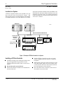
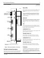
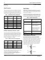
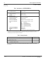
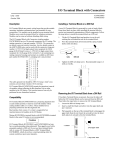
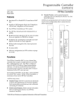
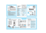
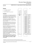
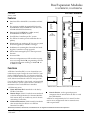
1
Bus Expansion Modules
IC697BEM742, IC697BEM744
62
FIP Bus Controller
GFK-1002E
January 1998
Bus Expansion Modules
a45466
Features
H
Interfaces FIP or World FIP I/O serial bus to IC697
PLC
H
Two versions available for standard IC697 racks:
IC697BEM742 and IC697BEM744 - both have 2M
of RAM and 2M of Flash memory
H
Data rate for IC697BEM742 is 1 Mbit/second,
IC697BEM744 is 2.5 Mbits/second
H
H
Four FIP Bus Controllers per PLC system
H
RS-485 serial port attaches to PC for easy in-system
firmware upgrade (no PROMS to change)
H
Pushbutton for resetting Bus Controller and enabling Bus Controller to accept upgrades
H
FIP bus faults managed by PLC Alarm processor
Function
H
H
Six status LEDs
OK
RUN
CD 1
TEN 1
CD 2
TEN 2
BEM 742
FIP
FIELDBUS
CONTROLLER
FIP
FIELDBUS DUAL
CHANNEL CONTROLLER
FIP CH S2
1 MHZ
PUSH TO
RESET MODULE
Two FIP bus channels provide redundant bus capability
CHANNEL 1
6 D+
7 D–
CHANNEL 2
6 D+
7 D–
MODULE
IC697BEM742
LABEL
44A735979–003R01
Software configuration (no DIP switches or jumpers to set) using Windowsr programming software
configuration function running on Windowsr 95
or Windows NTr
Functions
A FIP Bus Controller (FBC) is a two channel bus controller that occupies a single slot in an IC697 PLC standard or VME Integrator rack. I/O devices on the FIP
bus are scanned asynchronously by the bus controller
and I/O data is transferred to the CPU once per scan.
Up to 31 Bus Controllers, of any kind, can be included
in an IC697 PLC system. Of the 31 Bus Controllers, a
maximum of four can be FIP Bus Controllers.
A FIP bus may serve:
H
H
H
IC697 and IC693 PLCs interfaced to the bus by
FIP Bus Controllers.
Remote Drops, IC693 I/O racks that are interfaced
to the bus through Remote I/O Scanner Modules.
Each remote drop can include any mix of discrete
and analog I/O modules.
Field Control Stations, Field Control I/O modules
that are interfaced to the bus via a FIP Bus
Interface Unit (BIU).
* BEM742 shown; BEM744 looks the same except for door label
H
Generic Devices, such as general-purpose
computers that are interfaced to the bus via a 3rd
Party FIP Module.
A FIP bus is used primarily for I/O control. It is also
used to store configuration data to remote devices
and to report faults.
r MS-DOS, Windows, Windows 95, and Windows NT are registered trademarks of Microsoft Corporation.
t
Series 90 -70 Programmable Controller Data Sheet Manual
GFK-0600F
62-1
Bus Expansion Modules
2
GFK-1002E
January 1998
FIP Bus Controller
which allows IC693 I/O modules to be on the FIP Bus. The
IC693 Remote I/O Scanner and the modules it serves are
referred to as a FIP I/O Nest. For detailed information
on the IC693 Remote I/O Scanner, refer to the Remote I/O
Scanner User’s Manual.
Location in a System
A FIP Bus Controller module can be installed in any I/O
slot in the CPU rack of an IC697 PLC system. The
following figure shows a typical installation with a FIP Bus
Controller connected to an IC693 Remote I/O Scanner
IC697 PLC
IC697 PLC
a46559
FBC
CPU
PS
FBC
CPU
PS
Optional Redundant FIP I/O Bus
FIP I/O Bus
Remote I/O Rack
Remote I/O Nest
Î
Î
ÎÎÎÎ
Î
FBC
Generic
Device
Î
Î
Î
CPU
FIP Interface Module
PS
Î
Î
ÎÎÎÎ
ÎÎÎÎÎ
Î
Î
Î
ÎÎÎÎÎ
ÎÎÎÎÎ
Scanner
Up to 8 Field Control
modules (4 shown).
Î
Î
Î
PS
Field Control
I/O Station
FIP Bus
Interface Unit
IC693 PLC
Optional Expansion Rack
Figure 1. Example of FIP Bus Controller In a System
Installing a FIP Bus Controller
H
H
H
Installation should not be attempted without referring to the applicable Programmable Controller
Installation Manual and the FIP Bus Controller User’s
Manual.
H
Push the FIP Bus Controller into the card guide
until it is aligned with the connector on the rack
backplane.
H
While pressing the upper and lower flanges on the
left of the module, push it into the connector until
it clicks onto the rack rails. Be sure that the board
has seated properly in the connector.
H
Bus connections to the connectors on the front of
the module can now be made.
Be sure that rack is powered down.
Position the FIP Bus Controller at its intended slot
location in the rack.
62-2
t
Series 90 -70 Programmable Controller Data Sheet Manual
GFK-0600F
Bus Expansion Modules
3
GFK-1002E
January 1998
FIP Bus Controller
a45465
Status LEDs
The six LEDs located on the front of the FIP Bus Controller display module status and communications
activity.
MODULE OK LED
RUN LED
CARRIER DETECT CH 1 LED
TRANSMIT ENABLE CH 1 LED
CARRIER DETECT CH 2 LED
TRANSMIT ENABLE CH 2 LED
BEM 742
The top two LEDs indicate module health. The bottom four LEDs indicate communications activity on
the FIP bus. Two LEDs are dedicated to each of the
two FIP channels.
FIP
RESTART
PUSHBUTTON
FIELDBUS DUAL
CHANNEL CONTROLLER
FIP CH S2
1 MHZ
PUSH TO
RESET MODULE
SERIAL PORT
RS–485
COMPATIBLE
CHANNEL 1
6 D+
7 D–
CHANNEL 2
6 D+
7 D–
MODULE
IC697BEM742
LABEL
44A735979–003R01
FIP BUS
CHANNEL 1
CONNECTOR
MODULE OK
Shows the status of the FIP Bus Controller. This LED
blinks during power-up diagnostics and should remain on as long as power is applied to the Bus Controller.
RUN
Shows the operational status of the FIP Bus Controller. This LED turns ON when the module is acting as
the Bus Arbiter for the FIP network.
CARRIER DETECT CH 1
This LED is ON when detecting a carrier signal on the
FIP bus attached to channel 1.
TRANSMIT ENABLE CH 1
FIP BUS
CHANNEL 2
CONNECTOR
This red LED is ON when the FIP Bus Controller
transmits data on the FIP bus attached to channel 1.
CARRIER DETECT CH 2
This LED is ON when detecting a carrier signal on the
FIP bus attached to channel 2.
BEM 742
TRANSMIT ENABLE CH 2
* BEM742 is shown; BEM744 looks the same except
for door label
Figure 2. FIP Bus Controller Module - User Features
FIP Bus Controller Description
Following is a basic description of the module features
(refer to Figure 2 for location of hardware features).
t
Series 90 -70 Programmable Controller Data Sheet Manual
GFK-0600F
This red LED is ON when the FIP Bus Controller
transmits data on the FIP bus attached to channel 2.
Pushbutton
A pushbutton located directly below the LEDs is provided as a means to enable the Bus Controller to accept an upgrade of its operating firmware. It is also
used to locally reset the Bus Controller in the event of
a watchdog timeout.
62-3
Bus Expansion Modules
4
GFK-1002E
January 1998
FIP Bus Controller
Serial Connector
The FIP Bus
The 15-pin Serial Connector on the FIP Bus Controller
provides for attachment of a PC computer to perform
an upgrade of the operating firmware of the Bus Controller. The port supports the RS-485 electrical standard.
The FIP bus is a shielded twisted-pair wire. Proper
cable selection is critical to successful operation of the
system. Suitable cable types are listed in the FIP Bus
Controller User’s Manual.
Table 1. RS-485 Serial Port Pin Assignments
Pin
Number
1
Signal Name
Pin
Number
Shield Ground
9
Signal Name
Termination
Resistor*
2
no connection
10
RXD–
3
no connection
11
RXD+
4
ATTACH
12
TD–
5
+5V (5 Volts DC)
13
TD+
6
RTS–
14
RTS+
7
0V (DC Ground)
15
CTS+
8
CTS+
Shell
Conservative wiring practices, as well as national and
local codes, require physical separation between control
circuits and power distribution or motor power. Refer
to sections 430 and 725 of the National Electric Code.
Table 3. FIP Bus Characteristics
Bus Type
Single twisted pair plus
shield. Fiber optics cable and
modems can also be used.
Baud Rate
BEM742: 1.0 Mbaud
BEM744: 2.5 Mbaud
Maximum Bus Length
1000 meters per section (for
1.0 Mbaud,); 500 meters per
section for 2.5 Mbaud
Board Frame
Ground
4000 meters per network for
1.0 Mbaud; 2000 meters per
network for 2.5 Mbaud.
3 repeaters per network.
* A 120 ohm resistor is capacitively coupled to the board frame ground.
FIP Bus Connectors (Channel 1 and 2)
Two 9-pin connectors on the FIP Bus Controller provide for attachment of one or two FIP busses. The top
9-pin connector is for FIP bus Channel 1 and the bottom 9-pin connector is for FIP bus Channel 2. Since
signals on both busses are identical, the two busses
provide a redundant bus capability.
Table 2. FIP Bus Connector Pin Assignments
Pin
Number Signal Name
Pin
Number
Signal name
1
no connection
6
D+
2
no connection
7
D–
3
no connection
8
no connection
4
no connection
9
no connection
5
no connection
Shell
Maximum Number of
Devices
32 devices per section
DataEncoding
Manchester II Encoding
Connecting the Serial Bus
For information about bus selection and installation,
please refer to the FIP Bus Controller User’s Manual.
Connect the bus cable to the connector(s) on the front
of the Bus Controller. When installed in a single media or simplex configuration, either connector can be
used. When installed in a dual media or redundant
configuration, both the Channel 1 and 2 connectors
must be used. Both connectors accept a standard
9-pin D-type male connector.
D+
D–
Signal Ground*
Channel 1
* The connector shell is capacitively coupled to the board frame ground.
Note that if cables with plastic shell connectors are not
connected to both ports, the provided plastic
connector cover and nylon screws should be used to
cover the exposed metal connector of the FIP
communication port not used.
62-4
D+
D–
t
Channel 2
Series 90 -70 Programmable Controller Data Sheet Manual
GFK-0600F
Bus Expansion Modules
5
GFK-1002E
January 1998
FIP Bus Controller
Bus Controller Operation
H
The Bus Controller handles all data transfer between
the PLC and the devices on its bus. In order to do
this, the Bus Controller must interface two completely
separate and asynchronous activities:
Allows the broadcast of any aperiodic I/O data by
any 3rd Party device but only for the maximum
time configured (optional)
H
Allows the transmission of any messages by any
device but only for the maximum time configured
(optional)
H
Receives a diagnostic message from each IC6**
device
A. The FIP bus scan, a cycle of communications
between the devices on a bus (including the Bus
Controller itself).
B. The CPU sweep, the cycle of actions that includes
communications between the CPU and the Bus
Controller.
The Bus Controller manages data transfer between
the bus and the CPU by maintaining two separate
on-board RAM memories. One interfaces with the
bus and the other interfaces with the CPU. The Bus
Controller automatically transfers data between these
two memories, making data available to the bus or to
the CPU when it is needed.
The FIP Bus Scan
A FIP bus scan (also referred to as a macro-cycle) consists of a fixed set of operations that are repeated as
long as the RUN LED of the FIP Bus Controller is ON.
The length of the macro-cycle, once configured never
varies. Therefore, the bus scan is fixed.
Diagnostics
FIP devices on the bus will automatically report faults,
alarms and certain other predefined conditions to the
PLC.
The Bus Controller stores any diagnostic messages it
receives. They are read automatically by the IC697
CPU. Faults can then be displayed in the fault table
using the Windows programming software and
cleared from the programmer. Detailed information
on faults on the FIP bus can be found in Chapter 5 of
the FIP Bus Controller User’s Manual.
In addition to the built-in diagnostics capabilities of FIP
devices, the Windows programming software application program can make use of additional diagnostics
mechanisms provided by the IC697 PLC.
H
System Status References that have been defined
for FIP use.
H
Fault and No Fault contacts that can be used to
detect fault and lack of fault conditions.
H
Alarm contacts that can be used to indicate when
an analog value has reached an assigned alarm
limit.
During the bus scan, the FIP Bus Controller:
H
Requests all produced data from all devices to be
broadcast on the FIP network, at the predefined
period
H
Independently tests the presence of any remote
devices (optional)
Table 4. Applicable Manuals
Reference
t
Title
1
IC697 FIP Bus Controller User’s Manual
2
IC693 FIP Remote I/O Scanner User’s Manual
3
IC670 FIP Bus Interface Unit User’s Manual
4
Programmable Controller Installation Manual
5
Programming Software User’s Manual
6
Programmable Controller Reference Manual
Series 90 -70 Programmable Controller Data Sheet Manual
GFK-0600F
62-5
Bus Expansion Modules
6
GFK-1002E
January 1998
FIP Bus Controller
Table 5. Specifications for IC697BEM742/BEM744 [
OperatingConditions:
Atmospheric Pressure
80 kPa to 108 kPa
Storage and TransportCharacteristics
Atmospheric Pressure
66 kPa to 108 kPa
Free Fall
250mm (9.84 inches)
GeneralSpecifications
Module Operating Voltage
5 VDC (from backplane)
ModuleCurrent Drain
1.4 Amps, typical
Memory for IC697BEM742
2 Megabytes of RAM, 2 Megabytes of Flash
Memory for IC697BEM744
2 Megabytes of RAM, 2 Megabytes of Flash
LEDs
OK
RUN
CD 1
TEN 1
CD 2
TEN 2
Data Rate for IC697BEM742
Data Rate for IC697BEM744
Protocol
VME
1Mbit/second
2.5Mbits/second
FIP/W
orld FIP
System designed to support the VME standard C.1
Module OK
Bus Arbiter Status
Carrier Detect Channel 1
Transmit Enable Channel 1,
Carrier Detect Channel 2
Transmit Enable Channel 2
[ Refer to GFK-0867B, or later for product standards and general specifications. For installations requiring
compliance to more stringent requirements (for example, FCC or European Union Directives), refer to
InstallationRequirements for Conformance to Standards.
Table 6. Ordering Information
Description
Catalog Number
FIP Bus Controller Module, 2 Mbytes of RAM and 2 Mbytes of Flash memory
(Data Rate: 1 Mbit/second)
IC697BEM742
FIP Bus Controller Module, 2 Mbytes of RAM and 2 Mbytes of Flash memory
(DataRate:2.5Mbit/second)
IC697BEM744
Note: For Conformal Coat option, or Low Temperature Testing option please consult the factory for price
andavailability.
62-6
t
Series 90 -70 Programmable Controller Data Sheet Manual
GFK-0600F