1
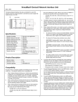
I/O Terminal Block with Connectors
IC670CHS003
IC670CHS103
GFK–1188F
October 2004
Description
Installing a Terminal Block on a DIN Rail
I/O Terminal Blocks are generic wiring bases that provide module
mounting, backplane communications, and terminals for user
connections. Two modules can be installed on one terminal block.
Modules screw onto the terminal block for vibration resistance.
Modules can be removed without disturbing field wiring.
A new I/O Terminal Block is protected by a pair of sturdy labels.
Keep these labels in place while installing the terminal block to
prevent environmental contamination of block components. Follow
the steps below to install the terminal block on a DIN rail.
The I/O Terminal Block with Connectors (catalog number
IC670CHS003) has two 20–pin male connectors for I/O wiring. The
mating connector is Amp part number 178289-8. The connectors
are keyed to prevent incorrect insertion. Any tin–plated contact in
the AMP D-3000 series can be used with the connector (Amp part
number 1-175217-5 for high contact force receptacle for 20-24
gauge (0.20-0.56mm2) wires), 1-175218-5 for high contact force
receptacle for 16-20 gauge (0.56-1.42mm2)). A kit containing two
mating connector housings and contacts is available as GE Fanuc
part number IC670ACC003. A crimping tool is not provided.
10
9
8
7
6
5
4
3
2
1
11
12
13
14
15
16
A2
A1
B2
B1
The safety ground wire should be AWG #14 (avg 2.1mm2 cross
section), not more than 4 inches (10.16 cm) long.
I/O Terminal Block IC670CHS103 permits hot insertion/ removal
of modules without affecting the Bus Interface Unit or other
modules in the I/O Station. Hot insertion/removal can only be
performed in non–hazardous locations.
Compatibility
I/O Terminal Block IC670CHS103 has a projecting alignment slot
at each module position. It must be used with modules whose
catalog number suffix is J or above. These modules have a
projecting tab that fits into the alignment slot.
Bus Interface Unit version 2.1 or later is required for hot
insertion/removal of modules in the I/O Station.
Mixing IC670CHS10x terminal blocks with IC670CHS00x terminal
blocks in the same I/O station is not recommended.
1.
2.
Tilt the I/O Terminal Block and position it over the rail,
catching the rail behind the tabs in the terminal block.
Pivot the terminal block downward until the spring–loaded
latches click into place.
tabs
3.
DIN rail
Tighten the DIN rail clamp screw. Recommended torque is 4
in/lbs to 6 in/lbs.
Tighten
Removing the I/O Terminal Block from a DIN Rail
If Auxiliary Terminal Blocks are present, they must be taken off
before the I/O Terminal Block can be removed from the DIN rail.
Then follow the steps below to remove the I/O Terminal Block.
1. Loosen the DIN rail clamp screw.
2. Insert a small flat–blade screwdriver into the upper latch and
pry it outward.
3.
Pull up gently on the top of the terminal block to disengage the
upper latch from the rail. Insert the screwdriver into the lower
latch and pry it outward to free the terminal block.
Caution
I/O Terminal Blocks IC670CHS101 and IC670CHS001B or later
have a metal grounding strip underneath. They must be used with a
grounded conductive DIN rail. Do not use these terminal blocks
with A version I/O Terminal Blocks or BIU Terminal Block
IC670GBI001, which do not have a metal grounding strip; the
system would have poor noise immunity.
1. Loosen
2. Pry Upper latch
3. Pry Lower latch
I/O Terminal Block with Connectors
2
GFK–1188F
Connecting Bases
Using a Crimping Tool
Before installing modules on their terminal blocks, install the
connecting cable(s). The cable illustrated below is supplied with the
I/O Terminal Block. A set of three connecting cables is available as
renewal part number IC670CBL001. Optional 21-inch (0.53 meter)
cable is also available (only one longer cable can be used per I/O
station).
The pins provided with this Terminal Block must be installed on individual
wires using a crimping tool. The AMP™ Pro–Crimper™ II, Hand Tool
Assembly 90546–1 is recommended. The tool must be properly adjusted, as
detailed in the instructions that come with the tool.
Remove to access interbase cable connector
1. Strip the wire 3.96 to 4.75mm (0.156 to 0.187in), taking care not to nick
or cut wire strands.
2. Hold the tool with the back (wire side) facing you. Squeeze tool handles
together and allow them to open fully.
3. Holding the contact by the mating end, insert the contact—insulation
barrel first—through the front of the tool into the appropriate crimp
section. Position the contact with the mating end on the locator side of
the tool, so that the open “U” of the wire and insulation barrels face the
top of the tool. Place the contact up into the nest so that the movable
locator drops into the slot in the contact. Butt the front end of the wire
barrel against the movable locator.
NOTE: Be sure both sides of the insulation barrel are started evenly into
the crimping section. DO NOT attempt to crimp an improperly–
positioned contact.
Terminal Block
Connection Cable
The connectors are keyed to assure proper installation. After
installing the cable, be sure it is firmly seated on both
connectors.
Wiring for I/O Modules
4. Hold the contact in position and squeeze the tool handles together until
ratchet engages enough to hold the contact in position. DO NOT deform
insulation barrel or wire barrel.
5. Insert stripped wire into contact until it is butted against wire stop as
shown.
6. Holding wire in place, squeeze tool handles together until ratchet
releases.
7. Check the contact’s crimp height as described in the tool instruction
sheet. Adjust the crimp height if necessary before continuing.
Contact
In general, I/O wires and communications bus cable can be placed
randomly in a wiring trough for lengths of up to 50 feet. If wiring is
cord-tied (harnessed), do not include the bus cable in the harness,
since binding wires tightly together increases the coupling and
mechanical stress that can damage the relatively soft insulation of
some serial cable types. For more information about noise
immunity, please refer to the I/O Modules User’s Manual.
Power Wiring
I/O modules require field–side power for I/O devices. Power supply
connections can easily be “daisy–chained” between modules with
similar power requirements. Alternatively, separate supplies can be
used on any combination of modules to provide isolation as needed.
Suppression at the Output Load: For information about
suppression, please refer to the I/O Modules User’s Manual.
Strip
Locator
Wire Stop
S
Wire Inserted
to Stop
I/O Terminal Block with Barrier Terminals
3
GFK–1000F
I/O Module Keying (optional)
2.
To install an I/O module, position the module so that the cable
slot in the module housing is over the connecting cable.
The I/O Terminal Block is provided with a set of small keys that fit
into lettered slots on the terminal block. Use of keying is
recommended to ensure installation of the correct type of module in
each location.
End View
Cable Slot
I/O Terminal Block (Top View)
Connecting Cable
(cross section)
F G H J K
A B C D E
F G H J K
A B C D E
3.
Align the module with the base and press the module down
firmly. If you feel resistance, remove the module and check the
keying (if present). Also be sure the connecting cable is within
the cable slot.
4.
Tighten the module bolts to secure it. Minimum recommended
torque is 6 in/lbs. Maximum recommended torque is 9 in/lbs.
Keying Slots
Key clip
Refer to the following table for keying locations for various types of
I/O modules. The check marks in the table correspond to the keying
slots in the I/O Terminal Block.
Module ID: IC670...
MDL240
MDL241
MDL330, MDL331
MDD441, MDL640,
MDL644
MDL641
MDL642
MDL643
MDL730, MDL740,
ALG320, ALG330
MDL233
MDL742
MDL930
ALG230, ALG240
ALG630, ALG620
ALG310
Keying Locations
A B C D E F G H J
●
●
●
●
●
●
● ●
●
●
●
● ●
●
● ●
●
●
●
●
● ●
●
●
●
● ●
●
●
●
K
● ●
Removing Power
For I/O Terminal Blocks without the special alignment slot
(IC670CHS001, 002, and 003), inserting or removing an I/O
module during station operation may cause incorrect data to be
generated for the entire I/O station.
● ●
I/O Terminal Blocks with the projecting alignment slot
(IC670CHS101, 102, 103) are designed for module hot–insertion.
With these terminal blocks, modules can be inserted/removed
without removing power to the I/O station or affecting other devices
in the I/O station. External power to the module itself must be
removed for hot insertion/removal. Hot insertion/removal can only
be performed in non–hazardous locations.
●
Note: Inserting or removing an I/O module during station operation
may cause incorrect data to be generated.
● ●
● ●
● ●
●
●
● ● ● ● ● ●
●
● ●
●
● ●
●
● ●
Some Field Control modules may not make proper connection and
fail to power up when hot-inserted on Terminal Block
IC670CHS103B or earlier. Version IC670CHS103C (introduced in
October 2004) or later should be used instead.
Warnings
Module Installation
Caution
Electrostatic discharge can damage an I/O Module when it is
not installed on an I/O Terminal Block. Always observe good
ESD protection practices when handling an un–installed
module.
If the protective label is still in place on the I/O Terminal Block,
remove it before attempting to install an I/O Module.
Installing an I/O Module on the Base
1.
Before installing a module, remove the cable slot knockout(s)
where the module would cover the connecting cable. The
knockouts can be removed with pliers or by pressing out from
inside the housing.
This equipment is suitable for use in Class I, Division 2,
Groups A, B, C, and D or in non–hazardous locations only.
WARNING-Explosion Hazard-Substitution of components
may impair suitability for Class I, Division 2.
WARNING-Explosion Hazard-Do not disconnect equipment
unless power has been switched OFF or the area is known to
be non–hazardous.
When in hazardous locations, turn off power before replacing or
wiring modules. Do not remove or insert external modules with
power applied. Personal injury, system malfunction and/or
damage to the equipment may occur.
In non–hazardous locations, for personal safety field power
should be off while removing or inserting a high–voltage I/O
module. Avoid contact with module wiring and with the exposed
connectors on the I/O Terminal Block.