1
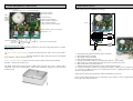
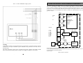
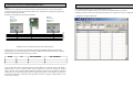
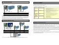
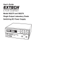
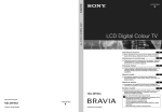
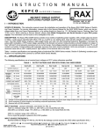
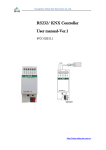
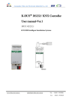
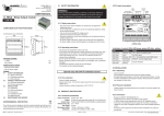
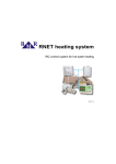
WARNING
The equipment makes a compact set of the switchboard. Just this set is safe from the point
of electrical shock. Therefore do not use other power supplies or circuits than mentioned in
this direction
The equipment is continuously powered from 230V/50Hz network. From this reason any
manipulation with the cabinet, leads or parts inside requires extensive care and can be executed just
by an authorized person (§6).
Technical description
MT24
User manual
The equipment is sufficiently covered just in an IP65 installation box against water and high
dampness (IP65 – dust proof, water jetting resistant). The protection itself is IP30.
Do not place the equipment necessarily in close vicinity of heat sources (heat guns, hot air
equipment, etc.).
The equipment will work reliably just in an environment given in this service manual. Any
arbitrary changes of operation and servicing can cause equipment function deterioration or
destruction.
GENERAL INSTRUCTIONS –GENERAL DESCRIPTION
It is intended for using within LV 3x230V 50Hz distribution network as an over line transfer unit. It can work in
several modes that are set up by the manufacturer according to customer’s requirement. The first mode is a threephase router and a signal amplifier. It enables messages routing among ModemTec PLC modems. It is mainly
used for PLC modules communication via distribution transformer or a very low impedance node. It can
obviously be used anywhere where the signal is to be branched out into more phases (max. three phases)
disregarding phase sequence. Voltage level of 230V AC must be kept however. Even several repeaters in various
nodes can be used. Very far-reaching PLC network can be established by means of MT24 series routers including
network where a signal must be routed among particular phases. Second mode is a pair communication between
two MT24 or MT24 and MT23R. It is a data transmission from one place to another. Any device like PC,
programmable automats or other equipment having RS232 communication link can be connected to MT24. A
third mode represents a network communication. This mode enables to establish a far-reaching data
communication network among one control center and several slave stations.
Operation state
It is a basic function of the equipment. The MT24 monitors the network in this state, evaluates an address and in
case of the proper address repeats a message over connected phases all at once with the maximum amplitude.
Subsequently it awaits another message reception. MT24 is multidirectional. It can make reception from any
phase and transmission over all phases. MT24 can communicate just with PLC modules working on the same
communication frequency. In the pair communication mode the MT24 passes immediately data from RS232 RX
toward other MT24 pair modem. That one will receive and retransmit them to RS232 output link. In the network
communication mode all is conformed to the main control station that distributes data to individual slave stations
and possibly responds to their answers.
Programming state
It is a state in which equipment parameters are set-up. It consists of computer connection to MT24 module over
serial port and its direct programming by means of „RSET-R“set up software. The description of that can be
found in „PLC routers of MT24 series configuration“.
“Beacon” function – see chapter „Other auxiliary function“.
PANEL DESCRIPTION AND ITS SIZE
BOX INSTALLATION
Main board description:
400mAT primary fuse
MT24 module electrical installation basic design:
2,5AT secondary fuse
CTS COM1 indication
RTS COM1 indication
230 V/
50Hz line
voltage
connection
terminals
3V real time battery
„POWER“ supply indication
Tx PLC transmission indication
Rx PLC reception indication
„Control“ processor status indication
CYKY 1,5
indikace signálu v pásmu 95 až 145 kHz
s amplitudou > 2 Všš
823 23 23 23 1
connection terminals
phase L3-N
1AT fuses
phase L2-N
phase L1-N
phase can be connected anyhow
Indication elements description:
Power supply indication – indicates MT24 connection to 230V line voltage and presence of 19VDC
output voltage.
Processor „Control“ status indication– indicates the main board CPU status, when lit, the system is
OK
Tx PLC transmission indication – -indicates transmission status from the processor toward MT24
power amplifier– when lit, transmission is on
Rx PLC reception indication– indicates processor reception status from the front end MT24
amplifier – when lit, the reception is on
The MT42 main board is placed inside of ABB 00878 box sized 310 x 240 x 110mm with a
transparent screw-on lid. IP55protection. After system assembling inside the box the protection
becomes a IP30.
5
9
11
6
10
Line feeder
230V 50Hz
CYKY
3 x 1,5
1 – WAGO 280-607 protection terminal+ 280-331 terminal
2 – WAGO 280-602 blue terminal
3 – WAGO 280-612 grey terminals
4 – DIN 35 ribbon (length as per box size)
5 – Cannon 9 pin RS232 connector for communication with PC– service COM2
6 – OBO V-TEC Pg 7 cable outlets and/or leak-proof side box outlets can be used
8 – DIN 35 ribbon end stop WAGO 246-116
9 – ABB 00 878 box with a transparent screw-on lid, IP55 protection IP55
10 – Cannon 9 pin RS232 connector for communication with PC– COM1 to beacon connection
11 - Cannon 9 pin RS232 connector for communication with PC– COM0 galvanically isolated –
exclusive communication port
Similar parts with equivalent parameters of other manufacturers can be used
Each of phase output terminals can be connected to various phases or even to different networks
having up to the voltage of 230VAC.
TN-C 3 x 230V 50Hz PEN voltage system
CONNECTION OF INPUT, OUTPUT TERMINALS AND RS232 BUS
The module has three serial RS232 lines. Two of them are dedicated to operation communication
with a PC, programmable automat or with other MT24 module. Both use a hardware RTS a CTS
control. The line 11 COM0 is completely galvanically isolated from the MT24. The line 10 COM1 is
galvanically connected with MT24. Both links route through a Cannon 9pin connector to the outside
installation box wall. The third RS232 line COM2 is a simple one without hardware control with no
galvanic isolation..
MT24
phase
L1
3-phase output
amplifiers
3-phase input
Active filters and
converters
L2
Galvanic
isolation
L3
COM2
cannon 9
RS 232
COM1
cannon 9
1- CD
2- RXD
3- TXD
4- DTR
5- GND
6- DSR
7- RTS
8- CTS
9- RI
COM0
cannon 9
230V
50Hz
Warning
As the MT24 module is not furnished with any disconnector a main disconnector must be
connected in its input terminals (3-pole minimum- the protection wire must not be
disconnected).
The main disconnector must easily accessible and properly marked. The MT24 module
line as well must be fused by fuses or breaker according to conductor cross-section.
L
N
3x buffer
RS232
processor
ALTERA
galvanic
isolation
amplifier
transmitter
receiver
RS 232 serial link serves for MT24 parameters set up.
Used 115200 Bd transmission rate does not allow a long interconnection cable (cca 2 m) according
to internal cable core parasitic capacity.
Protocol used:
8 bits, no parity, 2 stop bits
REPEATER - SIGNAL AMPLIFIER PRINCIPLE
PROGRAMMING STATE
Mode 1:
ModemTec PLC modems are associated intro logic segments in the PLC network. The modems
communicate directly inside of individual segments. The communication among the segments runs
by means of MT24 series routers.
Example of routing between two MT23R modems:
MT23R
Local Ad: 2
Remote Ad: 1
Segment: 1
MT23R
Local Ad: 1
Remote Ad: 2
Segment: 0
L1
L2
L3
N
PE
Routing between two MT23R modems upon different phases
On the picture is a connection of two MT23R connected upon different phases communicating
through MT24 router. The first MT23R is located in 0 segment and the other MT23R in 1 segment.
Routing table in the MT24 has the following contents:
FROM
TO
SRC SEGMENT
DST SEGMENT
1
1
0
1
2
2
1
0
As far as the router catches a message having a sender address in an interval from-to and sender’s
segment equals to the src segment column (source segment), the router will change the segment
value to the one of dst segment column (destination segment) and will repeat the message. Terminal
modems process just such messages which have equal both segment (1) and segment (2) addresses.
In order the mechanism is functional each equipment must have assigned a unique address in the
course of PLC network.
Prior to MT24 module usage a routing table must be set-up.
It is aligned through a RS232 serial port by means of PC and RSET-R set-up software.
Routing procedure in detail is described in the document “PLC MT24 series routers configuration”.
Configuration example in RSET-R:
.
PAIR MODE PRINCIPLE
Mode 2:
Just two modules can communicate between each other.
Various error states of the module can arise in the course of operation. Some of basic error states and
their trouble shooting are given as follows.
COM 0
MT24-1
COM 0
RS232
PLC-1
OPERATION ERRORS
MT24-2
RS232
Nr.
Indication LED
status
Trouble description
1
No LED is lit
modul není napájen
2
-
Check all fuses in power leads
Check connection leads for good connection
Learn if the equipment is not disconnected in the control room
Send a module to be serviced
CONTROL
Module does not
and POWER is lit communicate
other LEDs do
not blink
-
Check if the PLC transmission from MT23 is active
Check if the carrier frequency in PLC network e.g.. 85 kHz) is same
Check all fuses in communication connection branching
Check connection cables
Check if the equipment is not disconnected in the control room
Send a module to be serviced
3
CONTROL
module communicates
and POWER is lit sporadically
other LEDs blink
sometimes
-
Learn if the PLC transmission from MT23 is in the set-up mode
Check if the carrier frequency in PLC network e.g.. 85 kHz) is same
Check the PLC signal level and noise in connection point
4
CONTROL
module does not communicate
and POWER is lit with PC
other LEDs blink
sometimes
-
Check if the RS232 cable is properly connected
Communication rate set-up
RS232 data format set-up
Proper usage of RSET-R software
Send a module to be serviced
PLC-2
L1
L2
L3
N
PE
Warning:
Just one pair on a set up transmission frequency can be operated within a circuit of one distribution
transformer in this mode. When several pairs should be operated (maximum 3 pairs) then each pair
must use different transmission frequency. Frequencies in the range of 95kHz to 145kHz can be
used. Manufacturer sets the frequency up according to customer requirement.
Trouble shooting
NETWORK MODE PRINCIPLE
Mode 3:
OTHER AUXLIARY FUNCTIONS
PLC-3
COM 0
MT24
RS232
PLC-řídící
PLC-1
MT23R
PLC-2
PLC-4
To set up the MT24 K modem in modes 2 and 3 a RSET V1.0.7 P2 ÷ RSET V1.0.9 P2 software is used.
L1
L2
L3
N
PE
"Beacon" function
System enables very unique and simple communication test. The result of this test may be a map of
communication over power line network. The map may enable a design of a final version of modules
placement and system expansion or failure analysis simplification in the future.
MT24 modul is furnished by “Beacon” function. By a single plug-in of “Beacon” connector into
COM1 RS232 communication port the module will switch over to the state of permanent contacting
of MT22, MT23R modules or other ones. So it is possible to prove a communication between two
points of power network by means of two modules without any preparation and without a PC. This
makes possible to obtain a map of local energy node communication and choose an optimal PLC
communication set-up together with customer’s requirements.
Also a simple function test of MT24 module can be done by this way. As soon as beacon is inserted
in COM1 the module begins blinking – the yellow LED Tx PLC. Even a reception red LED of
power input blinks at the same time.
MAIN PARAMETERS
Power supply input:
Voltage
Frequency
Input power
230 V +10% - 15%
50 Hz ± 3%
cca 8 VA
cca 12 VA to 20 VA according to mark-space
transmission ratio
- standby
- transmitting
Signal inputs individually:
Voltage connected
Frequency
Current at 230V 50Hz
0 to ~230 V +10% - 15%
0 to 60 Hz
cca 35 mAef , cos φ = 0
High frequency signal:
Carrier frequency range
Amplitude into Rz = 10Ω
Current
Input sensitivity
S/N ratio
95 kHz ÷ 145 kHz
cca 10 Všš
cca 0,8 Ašš
cca 1 mV
min 9 dB
Values storage
NE
RS 232 COM2 :
Connector
Transmission rate
cannon 9 male
115200 Bd
8-N-1
Application
Hardware control
Galvanic isolation
data transmission toward PC – service mode
NO
NO
RS 232 COM1 :
Connector
Transmission rate adjustable
Data format
Application
Hardware control
Galvanic isolation
cannon 9 male
300 to115200 Bd
8-N-1
data transmission toward PC, PLC
YES
NO
RS 232 COM0 :
Connector
Transmission rate adjustable
Data format
Application
Hardware control
Galvanic isolation
cannon 9 male
300 to 115200 Bd
8-N-1
data transmission toward PC, PLC
YES
YES
Climate environment
Operation temperature
Limit temperature
Storage temperature
Protection
normal
- 30 °C to + 60 °C
- 40 °C to+ 70 °C
- 40 °C to + 70 °C
IP 30
Equipment complies with norms:
ČSN EN 61010-1, ČSN EN 60529,
ČSN EN 61000-6-2, ČSN EN 61000-6-3,