1
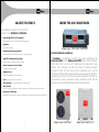
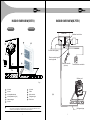
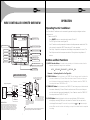
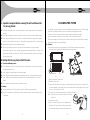
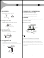
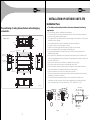
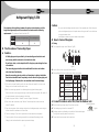
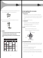
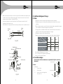
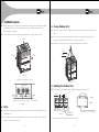
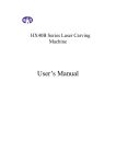
INSTALLATION & USER MANUAL
Model: DI10191A1 / DI10311A1 INDOOR UNIT
Model: DO10191A1 OUTDOOR UNIT
Model: DO10311A1 OUTDOOR UNIT
DUCTABLE AIR CONDITIONERS
Your unit may not be exactly same as depicted herein
Dear customer
Congratulation on buying ONIDA Ductable Air Conditioner.
Your Ductable Air Conditioner comes with ONIDA Guarantee of
Quality as detailed in the manual.
ONIDA takes great pride in providing its customers with stateof-the-art products that adheres to international quality
standards.
ONIDA is committed to following quality policy laid by our
chairman and managing director Mr. G. L. Mirchandani.
“We are committed to quality and strive for continuous
improvement through innovation and human development to
give customer better value for money always”
ONIDA stands committed to provide the ultimate customer
satisfaction, as nothing brings us greater joy than having
satisfied customers of ONIDA.
At ONIDA, feedback and suggestions based on your product
usage experience is greatly appreciated.
Please contact to us at [email protected]
G. Sundar
Chief Executive Officer
CONTENTS
Salient Features (5.5TR / 8.75TR)
1
Inside Air Conditioner
2
Inside Overview (5.5TR / 8.75TR)
3
Operation Precautions
5
Wire Controller Remote Overview
7
Operation
8
Indicators And Buttons
11
Operation Instructions
12
Maintenance & Service
14
Cleaning The Filter
16
Following Symptoms Are Not Air Conditioner Troubles
17
Unit Installation (5.5TR / 8.75TR)
19
Wiring Diagram (5.5TR / 8.75TR)
49
Trouble shooting
53
Precaution To Be Taken
56
Trial Run
57
Installation and Satisfaction Report
60
Warranty Terms & Conditions
62
Preventive Maintenance Service Coupon
64
Warranty Card(Customer Copy)
66
Warranty Card(service Centre Copy)
68
SALIENT FEATURES
INSIDE THE AIR CONDITIONER
Ductable Air Conditioner 5.5TR / 8.75TR
Model Code : D10191A1 / D10311A1
• Imported High BTU Scroll Compressor
High capacity of cooling, efficient, and energy-saving
• Low Noise
Lesser Noise design
Model Code : DI10191A1 / DI10311A1
• Trapezoidal internal grooved tube:
Increased the surface area to improve the cooling efficiency.
• High RPM Fan Motor with high static
Provides better air throw for uniform cooling
• Special insulation on the Air Outlet
To prevent dripping of water
• Hydrophilic fins
Makes the evaporator coil water proof
• Lock: Key lock and Fan lock features
• Sleep Function: Economy mode during sleeping time
Onida Ductable Air conditioner
All Ductable air conditioners consists of two main components, the
Indoor Unit (IDU) and the Outdoor unit (ODU). Indoor unit is installed in
Indoor side of the room to be air conditioned, the outdoor unit is kept
outside. This is because, all heat from inside is transferred outside,
through the ODU. The ODU houses the all important part of your air
conditioner. All Onida ODU’s are tested to be ensure longer life. The IDU is
mounted on one of the roof of the room to be air conditioned. The ODU can
be mounted on a wall, sunshade or skirting, outside the room. The two
units are connected through refrigerant pipes made of copper.
• Easy to install
Sleek, Slender and stylish get-up and Nested in the ceiling, Space-saving and noble
• Innovative Air Discharge
Innovative air supply, which provides homogeneous conditioning of the room temperature.
Model Code: DO10191A1
1
Model Code: DO10311A1
2
INSIDE OVERVIEW(5.5TR)
INDOOR UNIT
INSIDE OVERVIEW(8.75TR)
OUTDOOR UNIT
Indoor unit
3
7
Electrical control box
2
6
Drain orifice
5
4
Air return duct(option)
1
8
Remote controls signal
receiving board
9
TIMER ON
ECONOMICAL
CLOCK
TIMER OFF CONFIRM
M
MODE
FAN SPEED SWING
REPLACE LOCK
TEMP
10
COOL/
HEATING
1
Remote controller
(Optional)
Fixed rated wire controller
11
Outdoor unit
Fig.1
Air inlet(side and rear)
7
8
9
Wire controller
Air filter(inside air-in grill)
Heat exchanger
10
11
Refrigerant pipe
Drain hose
1
2
3
Air outlet
4
5
6
Air inlet
Air outlet
E-Box
Fig.2
Air inlet
NOTE
All the pictures in this manual are for explanation purpose only. They may be slightly different fr om the air
Refrigerant pipe
conditioner you purchased(depend on model).The actual shto ape shall prevail.
3
4
u
Operation Precautions:
£
Note:-
£
Read this manual carefully before operating the unit.
£
This air conditioner is designed to provide a comfortable room environment, and is
applicable to the purposes described in the manual only.
u
Inspection before operation:
£
Check whether the ground wire is broken or disconnected.
£
Check whether the air filter is installed properly.
£
If the air conditioner has been out of service for a long period, be sure to clean the filter
before resuming the service of the air conditioner. Cleanse it biweekly during continuous
service of the air conditioner.
£
Check that the air inlet and outlet of the indoor/outdoor unit are not blocked.
u
Safety Precautions:
£
Do not let the indoor unit or remote controller moistened. Otherwise, electric short-circuit or
fire may occur.
£
Do not use or store flammable gases or liquids near the air conditioner, e.g., hair styling jelly,
paint and gasoline. Otherwise, fire may occur.
£
When the fuse blows out, do not substitute any fuse of an improper nominal current value or
other wires. Substituting conductor or copper wire for fuse may cause damage to the air
conditioner or cause fire.
£
Do not insert any objects like sticks into the air inlet or outlet. It is very dangerous when the
blade touches any foreign objects during high-speed running of the fan.
£
Do not remove the fan cover of the outdoor unit. The fan without any external cover is
dangerous during high-speed running.
£
Do not use the main power switch to start up or shut down the air conditioner, but use the
ON/OFF button on the remote controller.
£
Do not repair the air conditioner by yourself. Delegate professional maintainers to do the
repair.
£
Cut off the main power switch before cleansing the filter and the unit body. This unit is
grounded and provides dual protection against accidental electric shock. No electric shock
will occur when you normally replace or cleanse the filter or use a dry cloth to clean the unit
body. However, to be on the safe side, cut off the power supply before performing
maintenance or up-keep work.
£
The electric circuit must be installed RCCB and manual switch.
£
The indoor relative humidity should be lower than 80%. If the air conditioner works in an
5
environment with a relative humidity higher than mentioned above, the surface of the air
conditioner may condensate. In this case, it is recommended to set the air speed of the
indoor unit to high.
£
If the air conditioner works in other than the above circumstances, functions may fail.
£
Before leaving the unit idle for a long period, cut off the main power switch, and remote the
batteries in the remote controller. When the main power switch is turned on, a certain extent
of electric power is consumed even if the air conditioner does not run. Turning off the main
power switch can save energy. Before restart the unit, please connect the power supply
advance 12 hours before restart the unit, for ensure the power the unit could perform in
normally.
£
Cleanse the air filter every another two weeks. The effect of cooling will be compromised if
the air filter is blocked.
£
Please consign professional personnel to check, clean and maintain the duct, drain system
regularly.
6
OPERATION
WIRE CONTROLLER REMOTE OVERVIEW
Operating Your Air Conditioner:
Your Ductable Air Conditioner can be conveniently operated using the intelligent cordless
remote control.
ON OF BUTTON
mode selection button
FAN SPEED SELECTION
timer on button
timer off button
TIMER ON
CLOCK
TIMER OFF
OK
AJUDSTMENT BUTTON
ECONOMICAL
MODE
FAN SPEED SWING
TEMP
AJUDSTMENT BUTTON
clock button
Switch on the MCB.
Press ON/OFF button on remote handset to switch ON the AC.
The "RUN" light on Indoor unit will glow ON.
Your AC switches on with parameters that were set before power was switched off. The
unit receives the signal with "BEEP" tone and your AC starts operation.
Time Delay: To protect the compressor, a time delay is incorporated in the circuit. The
Time Delay ensures that the compressor switches ON only after a delay of about 3
minutes.
SWING BUTTON
ok button
RESET
LOCK
COOL
HEATING
ECONOMICAL button
reset button
COOL ONLY/COOL AND
HEATING SELECTION BUTTON
LOCK BUTTON
Buttons and their Functions:
1) MODE Selection Button: It is used to select mode, push the button one time, then the
operation modes will change in turns as follows:
AUTO
COOLING DEHUMIDIFY HEATING
FAN
Remarks:- No Heating Mode for Cool Type Unit.
INSTALLATION PROCEDURE
Turn a screwdriver at the concave on bottom panel
of the Wire Controller to remove the Back Cover
Wire ControllerB ack Cover
Wiring Principle Sketch:
Infraed Pipe
Wire C o ntroller
Wire Joint, 5p
Wire ControllerTop Cover
5-Core Shield Cable,the length
is decided by installation
WoodM ounting Screw
(M4X20)
Wire Controller Bottom Cover
RUN
3) TIMER OFF Button: Push the button to set TIMER OFF, each time you push the button the
time moves forward by 0.5 hours. When the set time is over 10 hours, each time you
push the button the time moves forwarded by 1 hour. If want to cancel the TIMER OFF,
then adjust the time of TIMER OFF as 0.0.
Wire Controller LCD
Wire ControllerB oard
+5
GND
IndoorU nit Switch Board
Indoor Unit
When installing the Wire Controller, you should
adjust the bottom of the Wire Controller Board to
the Wire Controller Back Cover which should be
fixed first, then press the other end of the Wire
Controller Board.
Installation Notice:
When the air conditioner needs the constant frequency wire
Controller, be sure adding a Wire Joint with 5 terminal named
A,B,C,D,E in indoor unit, and fixing a infraed emitter whose
anode and cathode connecting with A and B near the receiver
in the Indoor Unit Switch Board,then connecting the terminal
+5v, GND, Run in the Switch Board to C,D,E respectively.
When installing the Wire Controller Cover,be
sure there is a hole in the wall to avoid t he Wire
Controller Back Cover being fixed directly to
the wall which is not allowed for the Wire Joint
extrudes out of the Wire Controller Back Cover
NOTE
Never turn screws too tightly, or else the cover would be dented or the Liquid Crystal breaks.
Please leave enough long cable for maintenance of the Wire Controller Board.
7
2) TIMER ON Button: Push the button, to set TIMER ON, each time you push the button the
time moves forward by 0.5 hours. When the set time is over 10 hours, each time you
push the button the time moves forwarded by 1 hour. If want to cancel the TIMER ON,
then adjust the time of TIMER ON as 0.0.
5) CLOCK Button: Normally display the clock set currently (display 12:00 for the first
electrifying or resetting). When push the button for 4 seconds, the hour part on the
and
button to adjust
clock display flashes every 0.5 seconds, then push button
minute. When set clock or alter clock setting, must push the confirm button to complete
the setting.
8
INDICATORS AND FUNCTIONS
NAME AND FUNCTION OF LCD ON THE WIRE CONTROLLER
5) OK Button: This button is used at the state of CLOCK adjustment. After select time, push this
button to confirm then exit, the current clock will display.
2
FAN speed
1
MODE display
6) RESET Button(Hidden): Use a small stick with a diameter of 1mm to push the RESET button
to cancel the current settings and get into the condition of resetting.
7) ON/OFF Button: Push the button at the condition of OFF, the OPERATION lamp lights, and
the wire controller enters into ON operation, simultaneously sends the information of
operation mode set currently, temperature, fan speed, timer etc. Push the button at the
condition of ON, the OPERATION lamp extinguishes, simultaneously sends the OFF. If
having set TIMER ON or TIMER OFF, the wire controller will cancel these settings before
entering into OFF, close the concern indicator, and then send the OFF information.
8) FAN SPEED selection Button: Select any one fan speed from “AUTO”, “LOW”, “MED”, and
“HIGH”.Each time push the button, the fan speed will change in turn as below mention.
9) ADJUSTMENT Button
: Push this button, indoor temperature increases. Push the button
continuously then the temperature increases by 10C per 0.5 seconds.
10) ADJUSTMENT Button
: Push this button, indoor temperature decreases. Push the button
continuously then the temperature decreases by 10C per 0.5 seconds.
11) SWING Button: Push this button for the first time when operation, it will start the swing
function. Push the button for the second time, cancel the swing function.
(The function is available matched with concerned unit).
12) ECONOMICAL Button: Push this button to set the Economical operation mode for air
conditioner, push again then cancel the mode. The operation is suitable for sleeping time.
13) COOL/HEAT Button(Hidden): Use a small stick with a diameter of 1mm to push the button
to switch modes. For COOLING ONLY type, it will be no heating mode when pressing
MODE. The uniform mode is COOLING and HEATING at the factory.
Remarks:- No Heating Mode for Cool Type Unit.
14) LOCK Button(Hidden): Use a small stick with a diameter of 1mm to push the LOCK button
to LOCK the current setting, push the button again then cancel the setting.
9
3
4
LOCK display
5
CLOCK display
6
OFF/ON display
7
Temperature display
Economical operation display
1) Mode Select Button (MODE): Press MODE button to select “COOL”, “DRY”, “HEAT”, or “FAN
ONLY” mode.(HEAT is invalid for COOL ONLY wire controller).
2) Fan Speed Button: Press FAN SPEED to select fan speed from “AUTO”, “LOW”, “MED”, and
“HIGH”.
NOTE:- some air conditioners have no MED fan speed, then the MED is regarded as HIGH.
3) Economical Operation Display: Press ECONOMICAL to display economical operation, if
press ECONOMICAL again then the display disappears.
4) LOCK Display: Press LOCK to display the icon of LOCK. Press the button again then the icon
of LOCK disappears. In the mode of LOCK, all the buttons are invalid except for LOCK
button.
5) CLOCK Display: Usually display the clock set currently. Press the button CLOCK for 4
seconds, the HOUR part will flash, press button and
to adjust HOUR. Press the
button CLOCK again, the minute part will flash, press button
and
to adjust MINUTE.
After clock set or clock operation, it must press OK to complete the set.
6) TIMER ON/OFF Display: Display ON at the state of TIMER ON adjustment or after only set
the TIMER ON; Display OFF at the state of TIMER OFF adjustment or after only set the
TIMER OFF; Display ON/OFF if simultaneously set the mode of TIMER ON & TIMER OFF.
7) Temperature Display Area: Usually display the set temperature. Press the buttons of and to
set temperature, at the mode of FAN, there is no figure display in the area.
NOTE: All items are shown in the above Figure for the purpose of clear presentation. But during
the actual operation only the relative functional items are shown on the display. All
the above icons will be displayed only when the remote controller is
electrified for the first time or reset.
10
OPERATION INSTRUCTIONS
£
Note:
AUTO Operation
«
Insert the power supply, operation lamp of indoor unit flashes.
Due to the difference of the set temperature of the unit and the actual indoor
1. Press MODE button to select AUTO Mode.
temperature, the Air Conditioner when in DRY mode will automatically operate many
2. Set the desired temperature by pressing the button
and
, usually the temperature range is
set from 170C~300C.
times without running the COOL and FAN mode.
TIMER Setting:
3. Press ON/OFF, the operation lamp of indoor unit lights, the air conditioner start operating at the
Button TIMER ON can set the starting time.
AUTO mode, the fan speed is controlled automatically, wire controller display screen
Button TIMER OFF can set the stopping time.
display “AUTO” the fan speed is un-adjustable. Press the button ON/OFF again, then the
1. To set the time of TIMER ON:
air conditioner stops operating.
1.1) Press button TIMER ON, the wire controller display SETTING, the icons of HOUR and ON
4. The ECONOMICAL button is available at the AUTO operation MODE.
COOL/HEAT (COOL ONLY unit hasn’t the function) /FAN ONLY Operation
1. Press the button MODE to select any one of “COOL”, “DRY”, “HEAT”, or “FAN ONLY” mode.
(NOTE:- HEAT MODE is invalid for COOL ONLY type units.)
2. Select the desired temperature by pressing the button
and
, usually the temperature range
is set from 170C~300C.
3. Press the button FAN SPEED to select any one of “AUTO”, “LOW”, “MIDDLE”, or “HIGH” fan
speed modes.
NOTE:- some air conditioners have no MED fan speed, then the MED is regarded as HIGH.
4. Press the button ON/OFF, the operation lamp on indoor unit lights, the air conditioner operates
according to the mode selected. Press the button ON/OFF again, stop the air conditioner.
REMARK: It can not set temperature at FAN Mode, and only operate step 1, 3, and 4. The
economical button is invalid at FAN Mode.
display on the timer setting area. The wire controller enter into the setting of TIMER ON.
1.2) Press button TIMER ON again, and then adjust the time of timer on as you desired.
1.3) Continuously Press the button, the time of timer will increase 0.5 hours per time. After the
time of timer reaches to 10 hours, the time will increase 1hour each time.
1.4) 0.5 seconds later, after finishing the adjustment, the wire controller sends the information of
timer on, the timer on setting is completed.
2. To set the time of TIMER OFF:
2.1) Press the button TIMER OFF, the wire controller display SETTING, the icons of HOUR and
OFF display on the timer setting area. The wire controller enters into the setting of timer off.
2.2) Press button TIMER OFF again, and then adjust the time of timer off as you desired.
2.3) Continuously press the button, the time of timer will increase 0.5 hours per time. After the
time of timer reaches to 10 hours, the time will increase 1 hour each time.
2.4) 0.5 seconds later, after finishing the adjustment, the wire conditioner sends the information
DRY Operation
of timer off, the timer off setting is completed.
1. Press MODE to select DRY Mode.
2. Select the desired temperature by pressing the button
and
, usually the temperature range
is set from 170C~300C.
2. To set the time of TIMER ON and TIMER OFF simultaneously:
3.1) Refer to step1 and step 2 of TIMER ON to set the TIMER ON.
3. Press the ON/OFF button. The operation lamp of indoor unit lights, and the air conditioner will
starts to operate in the DRY Mode. Press the ON/OFF button again to stop the air
conditioner.
3.2) Refer to step1 and step2 of TIMER OFF to set the TIMER OFF.
2.3) When set the TIMER ON and TIMER OFF simultaneously, if the set times of TIMER ON and
TIMER OFF are all over 10 hours, then TIMER OFF is always later 1 hour than TIMER ON.
2.4) 0.5 seconds later, after finishing the adjustment, the wire controller sends the information of
timer on/off, timer off and timer on setting are completed.
11
12
MAINTENANCE & SERVICE
Alter the timer
To alter the time of TIMER ON or TIMER OFF, press the timer button to confirm once more.
Adjust the time of TIMER ON and TIMER OFF as 0.0 to cancel the TIMER ON or TIMER OFF.
Note:1. The time of TIMER ON is the relative time; it is relative to the standard time of operating wire
controller. If having setting the TIMER ON or TIMER OFF, then the clock can not be
adjusted.
Warning:1. BE sure there are no barriers between the remote controller and the receiver of indoor unit
otherwise the air conditioner will not work.
2. Keep the Remote Controller away from all liquids.
3. Protect the Remote Controller from high temperatures and exposure to radiation.
4. Keep the indoor receiver out of direct sunlight otherwise the Air Conditioner may malfunction.
5. Keep controller away from EMI (Electro-Magnetic Interference) supplied by other household
appliances.
£
Important:£
Only the professionals can perform repair.
£
Before performing operation for the electric connectors or cleansing the filter, turn off the
main power switch.
£
Do not use water or air with a temperature higher than 500C to cleanse the filter or panel.
£
Check and maintain the ventilating slot once every half years, wash and maintain with
corresponding disinfection shall process once.
£
The filter can expel dust and other particles in the air. If it is blocked, the effect of the air
conditioner will be degraded. Therefore, clean it every another two weeks if you use the
air conditioner for a long period.
£
If the indoor unit is installed in a place with heavy dust, clean the filter more often.
£
If the stain is heavy and difficult to clean, replace the filter (the substitute filter is an
optional assembly in the sale).
£
Check if the wiring is not broken off or disconnected.
£
Use a dry cloth to wipe the indoor unit and remote controller.
£
A wet cloth may be used to clean the indoor unit if it is very dirty.
£
Never use a damp cloth on the remote controller.
£
Do not use a chemically-treted duster for wiping or leave such material on the unit for
long. It may damage or fade the surface of the unit.
£
Do not replace the power cable without permission. If the power cable is damaged,
specialized power cable must be used as substitute. Do not repair the air conditioner
without permission. The foregoing operations must be performed by the local distributor
or after sales service offices of Onida.
£
Do not use benzine, thinner, polishing powder, or similar solvents for cleaning. these
mau cause the plastic surface to crack or deform.
Maintenance & Upkeep Of Outdoor Unit:
£
£
The edge of some sheet metal assemblies and the fin of the condenser are very sharp.
Incorrect operation may cause harm. Be cautious when cleaning them up.
£
Check the air inlet and outlet of the outdoor unit periodically to see whether they are blocked
by stain or lampblack.
£
Contact the distributor or the after sales service center of Onida.
13
14
Operation
£
CLEANING THE FILTER
Required Before Leaving The Air Conditioner Idle
For A Long Period:
£
Let the air conditioner run in the air supply mode for about half a day, and let its interior be
fully dry.
£
Switch off the power by the button in remote controller, and then cut off the power supply.
£
When the main power switch is turned on, a certain extent of electric power is consumed
even if the air conditioner does not run. Turning off the main power switch can save energy.
£
Remove the batteries out of the remote controller.
£
After the air conditioner has been in service for several seasons, foreign substance
accumulates inside the unit to an extent dependent on working conditions. Therefore, shut
The air filter can prevent the dust or other particulate from going inside. In case of blockage
of the filter, the working efficiency of the air conditioner may greatly decrease.
Therefore, the filter must be cleaned once two weeks during long time usage.
If the air conditioner is installed in a dust place, clean the air filter frequently.
If the accumulated dust is too heavy to be cleaned, please replace the filter with a new one
(replaceable air filter is an optional fitting).
£
Caution:The control box cables, which are originally connected with the main body electrical
terminals must be pulled off before doing as indicated above.
down the air conditioner through the ON/OFF button of the remote controller, and then cut
off the power supply.
£
Startup After A Long Period Out Of Service:
£
Check the following issues:
£
Check whether the air inlet or outlet of the indoor unit and outdoor unit is blocked. Remove
foreign substance if any.
£
Check whether the ground wire is connected properly.
Fixed screw
Filter
£
Check whether the condensate water is discharged normally. (Cooling operation season).
£
Check whether the insulation work of refrigerant circuit and ventilating duct is on sound
status.
£
Check whether the installing seat is corroded or rusted.
£
Startup:
£
Connect the indoor unit 12 hours after connect the outdoor unit power supply.
£
Switch on the power control of remote controller or wire controller, and than startup the air
conditioner.
Fig.4
Fig.3
1. Figure.3 screw the Fixed screw.
2. Dismantle the air filter.
3. Clean the air filter (Vacuum cleaner or pure water may be used to clean the air filter. If the
dust accumulation is too heavy, Please use soft brush and mild detergent to clean it and
dry out in cool place).(See Fig.5).
4. The air-in side should face down when using water.(See Fig.4).
Note:- Do not dry out the air filter under direct sunshine
or with fire.
5. Re-install the air filter.
6. install and close the air-in grill in the reverse order
of step1 and 2 and connect the control box cables
to the corresponding terminators of the main body.
Fig.5
15
16
FOLLOWING SYMPTOMS ARE NOT AIR CONDITIONER
TROUBLES
Symptom 1: The system does not operate:
The air conditioner does not start immediately after the ON/OFF button on the remote
£
controller is pressed. If the operation lamp lights, the system is in normal condition. To
Symptom 4: Noise of air conditioners cooling:
Symptom 4.1: Indoor unit
£
A continuous low “shah” sound is heard when the systems is in cooling operation or
at a stop. When the drain pump (optional accessories) is in operation, this noise is
heard.
£
A “pishi-pishi” squeaking sound is heard when the systems stops after heating
prevent overloading of the compressor motor, the air conditioner starts 3 minutes after it is
operation. Expansion and contraction of plastic parts caused by temperature change
turned ON.
make this noise.
£
If the operation lamp and the “PRE-DEF indicator(cooling and heating type) or fan only
indicator(cooling only type)” light, it means you choose the heating model, When just
starting, if the compressor has not started, the indoor unit appears “anti cold wind”
protection because of its over low outlet temperature.
Symptom 2: Change into the fan mode during cooling mode:
£
In order to prevent the indoor evaporator frosting, the system will change into fan mode
automatically, restore to the cooling mode after soon.
£
When the room temperature drops to the set temperature, the compressor goes off and the
indoor unit changes to fan mode; when the temperature rises up, the compressor starts
again. It is same in the heating mode.
Note:- Heating operation is invalid in Cooling only type unit.
Symptom 4.2: Indoor unit, Outdoor unit
£
A continuous low hissing sound is heard when the system is in operation. This is the
sound of refrigerant gas flowing through both indoor and outdoor units.
£
A hissing sound which is heard at the start or immediately after stopping operation or
defrost operation. This is the noise of refrigerant caused by flow stop or flow change.
Symptom 4.3: Outdoor unit
£
When the tone of operating noise changes. This noise is caused by the change of
frequency.
Symptom 5: Dust comes out of the unit:
Symptom 3: White mist comes out of a unit:
Symptom 3.1: Indoor Unit
£
When the unit is used for the first time in a long time. This is because dust has gotten
into the unit.
£
When humidity is high during cooling operation If the interior of an indoor unit is extremely
contaminated, the temperature distribution inside a room becomes uneven. It is necessary
to clean the interior of the indoor unit. Ask your dealer for details on cleaning the unit. This
operation requires a qualified service person.
Symptom 6: The units can give off odors:
£
The unit can absorb the smell of rooms, furniture, cigarettes, etc., and then emit it
again.
Symptom 7: The outdoor unit fan does not spin:
Symptom 3.2: Indoor unit, Outdoor unit
£
When the system is changed over to heating operation after defrost operation Moisture
generated by defrost becomes steam and is exhausted.
£
During operation. The speed of the fan is controlled in order to optimize product
operation.
Note:- Heating operation is invalid in Cooling only type unit.
17
18
INDOOR INSTALLATION 5.5TR
£
Install the Main Body
?
Installation Space:-
£
Installing Φ10 hanging screw bolts. (4 bolts):
The indoor unit should be installed in a location that meets the following
requirements:
?
There is enough room for installation and maintenance.
?
The ceiling is horizontal, and its structure can endure the weight of the indoor unit.
?
The outlet and the inlet are not impeded, and the influence of external air is the least.
?
The air flow can reach throughout the room.
?
The connecting pipe and drainpipe could be extracted out easily.
?
There is no direct radiation from the heaters.
Maint enance roomage
t
Please refer to the following figures for the distance measurement between the screw bolts.
t
Please install with Φ10 hanging screw bolts.
t
The handling to the ceiling varies from the constructions, consult the construction personals
for the specific procedures.
t
The size of the ceiling to be handled------ Do keep the ceiling flat. Consolidate the roof
beam for possible vibration.
t
Carry out the pipe and line operation in the ceiling after finishing the installation of the main
body. While choosing where to start the operation, determine the direction of the pipes to be
drawn out. Especially in case there is a ceiling, position the refrigerant pipes, drain pipes,
500mm or more
600mm or more
indoor & outdoor lines to the connection places before hanging up the machine.
t
The installation of hanging screw bolts.
t
Cut off the roof beam.
t
Strengthen the place that has been cut off, and consolidate the roof beam.
600mmX600mm
checking orifice
Fig.6
t
After the selection of installation location, position the refrigerant pipes, drain pipes indoor &
outdoor wires to the connection places before hanging up the machine.
t
The installation of hanging screw bolts.
t
Note:- Confirm the minimum drain tilt is 1/100 or more.
?
Note:-
t
Wooden Construction:
Keep indoor unit, outdoor unit, power supply wiring and transmission wiring at least
1 meter away from televisions and radios. This is to prevent image interference and
noise in those electrical appliances. (Noise may be generated depending on the
conditions under which the electric wave is generated, even if 1 meter is kept.)
Put the square timber traversal over the roof beam, then install the hanging screw bolts.
(Refer Fig.7).
Timber over the beam
Roof beam
Ceiling
Hanging screw bolts
Fig.7
19
20
New concrete bricks:£
£
Diagrammatic sketch for installing the main body:-
Inlaying or embedding the screw bolts. (Refer to Fig.8).
£
Installing the dust proof net and canvas air passage
1.Install the dust proof net according to the installation manual.
2.Install the canvas air passage underneath the dust proof net.
Blade shape insertion
Slide insertion
Fig.8
£
Duct Design:1. Air inlet and air outlet duct should be apart far enough to prevent air outlet entering Air inlet.
£
For Original concrete Bricks:-
2. There is dust filter on the indoor unit.
Use embedding screw bold, crock and stick harness. (Refer to Fig.9)
£
Recommended duct connection
Canvas tie-in Canvas tie-in
Steel bar
Embedding screw bolt
(Pipe hanging and embedding screw bolt)
Isolation booth
Fig.9
£
Steel roof beam structure:-
Air outlet
Isolation booth
Install and use directly the supporting angle steel. (Refer to Fig.10)
checking orifice
Hanging screw bolt
Air inlet
Air dust filter
Fig.12
£
Note:-
1. Do not put the connecting duct weight on the indoor unit.
Supporting
angle steel
Hanging bolts
2. When connecting duct, use inflammable canvas tie-in to prevent vibrating.
Fig.10
3. When connecting duct, install in place prone to takedown for maintenance.
£
Overhanging the Indoor unit:-
4. Change the fan motor static pressure corresponding to external duct static pressure.
(1) Overhang the indoor unit onto the hanging screw bolts with block.
(2) Position the indoor unit in a flat level by using the level indicator, unless it may cause
leakage.
Screw nut
5. If installed in place like meeting room where noise is easy to be perceived, design isolation
booth and internal duct under layer to muffle the duct system and weaken the air encounter
& Noise in the duct
Shockproof cushion
Overhang part
Washer
Hanging
screw bolt
Fig.11
21
22
INSTALLATION OF OUTDOOR UNIT 5.5TR
Installation Place
The positioning of ceiling hole and indoor unit and hanging
screw bolts:135
88
82
82
400
270
249
Unit: mm
PLASTIC COVER
24
68
ELECTRICAL CONTROL BOX
46
AIR INTAKE
4-12*25 OBLONG SUSPENTION BOLT HOLES
1148
69
28
179
136
4-Φ5 HOLES FOR AIR
OUTLET DUCT CONNECTION
AIR INTAKE DUCT FLANGE
11
400
400
691
136
125
1148
1200
SAFETY DRAIN CONNECTING PIPE
82
31
82
339
AIR OUTLET
64
1073
Fig.13
(Wall or obstacle)
Strong wind
≥30cm
65
15
153
17
35
37
15
6-Φ5 HOLES FOR AIR
OUTLET DUCT CONNECTION
AIR OUTLET DUCT FLANGE
253
638
638
600
11
REFRIGERANT-PIPE FLARED
CONNECTION Φ19(3/4)
123
14
28
123
52
15
50
15
169
90
800
144
136
179
REFRIGERANT-PIPE FLARED
CONNECTION Φ12.7(1/2)
137
15
CONNECTING POINT OF DRAIN PIPE
169
Air inlet
≥30cm
Maintain channel
N
≥60cm
P
Air inlet
≥200cm
MODEL 19.3kW
56
29
930
l
The Outdoor unit should be installed in the location that meets the following
requirements:
?
There is enough room for installation and maintenance.
?
The air outlet and the air inlet are not impeded, and can not be reached by strong wind.
?
It must be a dry and well ventilating place.
?
The support is flat and horizontal and can stand the weight of the outdoor unit. And will no
additional noise or vibration.
?
Your neighborhood will not feel uncomfortable with noise or expelled air.
?
It is easy to install the connecting pipes or cables.
?
Determine the air outlet direction where the discharged air is not blocked.
?
There is no danger of fire due to leakage of inflammable gas.
?
The piping length between the outdoor unit and the indoor unit may not exceed the
allowable piping length.
?
In the case that the installation place is exposed to strong wind such as seaside, make
sure the fan operating properly by putting the unit lengthwise along the wall or using a dust
or shield. (Refer Fig.14)
?
If possible, do not install the unit where it is exposed to direct sunlight.
?
If necessary, install a blind that does not interfere with the air flow.
?
Select the position where it will not be subject to snow drifts, accumulation of leaves or
other seasonal debris. If unavoidable, please cover it with a shelter.
?
Locate the outdoor unit as close to the indoor unit as possible.
?
If possible, please remove the obstacles nearby to prevent the performance from being
impeded by too little of air circulation.
?
The minimum distance between the outdoor unit and obstacles described in the
installation chart does not mean that the same is applicable to the situation of airtight
room. Leave open two of the three directions (M, N, P). (Refer Fig.15, Fig.17)
X
O
M
Air outlet
Fig.15
Fig.14
23
24
£
Overall View of Outdoor Unit:-
£
Moving and Installation:
£
Since the gravity center of the unit is not at its physical center, so please be careful when
lifting it with a sling.
£
Never hold the inlet of the outdoor unit to prevent it from deforming.
£
Do not touch the fan with hands or with other object.
£
Do not lean it more than 450, and do not lay it sidelong.
£
Make concrete foundation according to the specifications of the outdoor units. (Refer
Fig.17).
£
Fasten the feet of this unit with bolts firmly to prevent it from collapsing in case of
> 60 c m
1167
earthquake or strong wind. (Refer Fig.17.)
Fig.17
Fix with bolt
900
330
378
400
340
590
Fig.16
25
26
Refrigerant Piping 5.5TR
Caution:
Check whether the height drop between the indoor unit and outdoor unit, the
length of refrigerant pipe, and the number of the bends meet the following
requirements: (The number of bends less than 10)
Model
The length of refrigerant pipe
The max height drop
Be sure to with insulating materials cover all the exposed parts of the flare pipe
joints and refrigerant pipe on the liquid-side and the gas-side. Ensure that there
is no gap between them.
Incomplete insulation may cause water condensation.
£
How to Connect the pipes:
60
30
15
£
Flaring
£
Cut a pipe with a pipe cutter. (Refer to Fig.18).
£
The Procedure of Connecting Pipes:
£
Caution:All field piping must be provided by a licensed refrigerant technician and
must comply with the relevant local and national codes.
Do not let air, dust, or other impurities fall in the pipe system during the time
of installation.
The connecting pipe should not be installed until the indoor and outdoor
units have been fixed already.
Fig.18
£
Insert a flare nut into a pipe and flare the pipe.
£
Refer to Below Table for the dimension of flare nut spaces.
Keep the connecting pipe dry, and do not let moisture in during installation.
Execute heat insulation work completely on both sides of the gas piping and
the liquid piping. Otherwise, this can sometimes result in water leakage.
1) Drill a hole in the wall (suitable just for the size of the wall conduit), then set on the
fittings such as the wall conduit and its cover.
2) Bind the connecting pipe and the cables together tightly with binding tapes.
Pass the bound connecting pipe through the wall conduct from outside. Be careful of
the pipe allocation to do on damage to the tubing.
3) Connect the pipes. Refer to “How to Connect the pipes” for details.
4) Expel the air with a vacuum pump. Refer to “How to expel the air with a vacuum
pump” for details.
5) Open the stop values of the outdoor unit to make the refrigerant pipe connecting the
indoor unit with the outdoor unit in fluent flow.
6) Check the leakage. Check all the joints with the leak detector or soap water.
7) Cover the joints of the connecting pipe with the soundproof/ insulating sheath
(fittings), and bind it well with the tapes to prevent leakage.
27
Pipe gauge
Flare dimensin A
min (mm) max
Tightening torque
Ø 6.4
14.2~ 17.2 N.m
(144~176 kgf.cm)
8.3
8.7
Ø 9.5
32.7~ 39.9 N.m
(333~407 kgf.cm)
12.0
12.4
Ø12.7
49.5~ 60.3 N.m
(504~616 kgf.cm)
15.4
15.8
Ø15.9
61.8~ 75.4 N.m
(630~770 kgf.cm)
18.6
19.0
97.2~ 118.6 N.m
(990~1210 kgf.cm)
22.9
23.3
Ø19
Flare shape
90
°± 4
45 °
±2
A
R0.4~0.8
£
Connect the Indoor unit at first, then the Outdoor unit.
£
Bend the tubing in proper way. Do not harm to them.
Bend the pipe with thumb
0
£
The bending angle should not exceed 90 .
£
Bending position is preferably in the middle of the bendable pipe.
The larger the bending radius the better it is.
£
Do not bend the pipe more than three times.
28
Fig.19
min-radius 100mm
£
When connecting the flare nut, coat the flare both inside and outside with either oil or
ester oil and initially tighten by hand 3 or 4 turns before tighten firmly.
Fig.20
£
Be sure to use both a spanner and torque wrench together when connecting or
disconnecting pipes to / from the unit.
Fig.21
£
How to expel the air with a vacuum pump:
Stop valve operation introduction
1. Opening stop valve
1. Remove the cap and turn the valve counter clock-wise with the hexagon wrench.
2. Turn it until the shaft stops. Do not apply excessive force to stop valve. Doing so may
break the valve body, as the valve is not a back seat type. Always use the special
tool.
3. Make sure to tighten the cap securely.
2. Closing stop valve
1. Remove the cap and turn the valve clockwise with the hexagon wrench.
2. Securely tighten the valve until the shaft contacts the main body seal.
3. Make sure to tighten the cap securely.
4. For the tightening torque, refer above mentioned table.
£
Caution:
Always use a charge hose for service port connection.
After tightening the cap, check that no refrigerant leaks are present.
£
Caution:-
service port
Too large torque will harm the bellmouthing and too small will cause leakage.
Please determine the torque according to below given Table.
maintenance nut
After the connecting work is finished, be sure to check that there is no gas
leak.
cap
Fig.22
Tightening torque N M (Turn clockwise to close)
Stop
Valve size
Ø6.4
Ø9.5
Ø12.7
Ø15.9
Shaft (valve body)
5.4~6.6
8.1~9.9
seal
Maintenance nut
18~22
13.5~16.5
23~27
27~33
Hexagonal
wrench
10 mm
36~44
29
shaft
hexagon hole
£
Using the Vacuum Pump:
1.
13.5~16.5
Hexagonal
wrench 6 mm
Ø22.2
Ø25.4
Hexagonal
wrench 4 mm
Cap
(Valve lid)
11.5 ~ 13.9
2.
3.
4.
Loosen and remove the maintenance nuts of stop valve A and B, and connect the charge
hose of the manifold valve to the service port of stop valve A. (Be sure that stop valves A
and B are both closed).
Connect the joint of the charge hose with the vacuum pump.
Open the Lo-lever of the manifold valve completely.
Turn on the vacuum pump. At the beginning of pumping, loosen the maintenance nut of
stop valve B a little to check whether the air comes in (the sound of the pump changes,
and the indicator of compound meter turns below zero). Then fasten the maintenance nut.
30
5.
When the pumping has finished, close the Lo-lever of the manifold valve completely and
turn off the vacuum pump. Make pumping for 15 minutes or more and check that the
compound meter indicates -76cmHg(-1X10⁵Pa).
6.
Loosen and remove the cap of stop valves A and B to open stop valve A and B
completely, then fasten the cap.
7.
Disassemble the charge hose from the service port of stop valve A, and fasten the nut.
Outdoor
unit
Indoor
unit
A
Gas side
C
Liquid side D
£
Additional Refrigerant Charge :
£
Note:1. Refrigerant cannot be charged until field wiring has been completed.
2. Refrigerant may only be charged after performing the leak test and the vacuum
pumping.
3. When charging a system, care shall be taken that its maximum permissible charge is
never exceeded, in view of the danger of liquid hammer.
4. Charging with an unsuitable substance may cause explosions and accidents, so
always ensure that the appropriate refrigerant is charged.
5. Refrigerant containers shall be opened slowly.
6. Always use protective gloves and protect your eyes when charging refrigerant.
B
R(g)
Stop valve
D(mm)
Ø 9.5
Ø 6.4
Ø12.7
L(m)
Fig. 23
Less than 5m (One-way)
Manifold valve
Added Refrigerant When
Over 5m (One-way)
Pressure meter
Multi-meter
30g/m×(L-5) 65g/m×(L-5) 115g/m×(L-5)
R(g): Additional Refrigerant to be charge.
L(m): The length of the refrigerant pipe(one-way)
D(mm): Liquid side pipe Diameter
-76 cmHg
Hi-lever
Lo-lever
Charge hose
Vacuum pump
£
Check the Leakage:
Check all joints with the leak detector or soap water(See Fig.25 as a reference
illustration).
Check-point of indoor unit
D
C
B
A
£
Note:-
Lo-lever
Fig.24
In the figure:
A..............Lo-stop valve
B..............Hi-stop valve
C, D.........Joints of the connecting pipe to
the indoor unit.
Check-point of outdoor unit
Fig.25
31
32
CONNECT THE DRAIN PIPE 5.5TR
£
Install the drainpipe of the indoor unit:
The outlet has PTI screw bread, please use sealing materials and pipe sheath(fitting)
when connecting PVC pipes.
£
Caution:£
The drain pipe of indoor unit must be heat insulated, or it will condense dew, as well
as the connections of the indoor unit.
£
Hard PVC binder must be used for pipe connection, and make sure there is no
leakage.
£
With the connection part to the indoor unit, please be noted not to impose pressure
100
70
£
When the declivity of the drain pipe downwards is over 1/100, there should not be any
80
60
on the side of indoor unit pipes.
winding.
Fig.27
£
The total length of the drain pipe when pulled out traversals shall not exceed 20m,
when the pipe is over long, a prop stand must be installed to prevent winding.
£
Refer to the under figures for the installation of the pipes.
£
Drainage test:
£
Check whether the drainpipe is unhindered.
£
New built house should have this test done before paving the ceiling.
Water to the recelver
through the stow tube
1.5m~2m
Insulating Downward declivity
material lower than 1/100
Test cover
Bend
S shape
Put as deep as possible
(about 10cm)
Downward declivity
lower than 1/100
Fig.28
£
Install the drain joint of the outdoor unit
Fit the seal into the drain joint, then insert the drain joint into the base pan hole of
outdoor, rotate 900 to securely assemble them. Connect the drain joint with an
extension drain hose (Locally purchased).(Refer to Fig.29)
Seal
The base pan hole
of outdoor unit
Drain elbow
VP30
The base pan
hole of outdoor
Fig.26
33
Fig.29
34
Seal
Drain
elbow
CONNECTIVE DIAGRAM 5.5TR
INDOOR UNIT INSTALLATION 8.75TR
?
Installation Space:Ensure enough space required for installation and maintenance.
Over 500 mm
Gas side
Liquid side
Maintenance space
Orifice
£
Note:
Over 600 mm
Fig.30
600mmX600mm
For ensuring throttled efficiency. Please mount the Orifice as horizontally as possible;
and anti-shock rubber should be wrapped at external of the Orifice for denoise.
Inspection orifice
Fig.32
£
Caution:£
Mark the data plate with the Orifice installed.
£
Please purchase the fittings according to the requirements in the manual strictly.
£
Refer the diagram when installing.
Liquid side
Liquid side
Liquid side
Outdoor
Indoor
Outdoor
Indoor
Note: Ensure that the minimum
Outdoor
Indoor
drain gradient is over 1/100.
Inspection orifice
X
Fig. 31
Fig.33
?
Install Φ10 Pendant Bolts or Ground Bolts:-
£
Preinstalled Orifice:
Pendant bolt hole
4-12×72
Cooling only
Cooling &Heating
3-PHASE
117
/
760
D10191A1
50Hz
840
800
MODEL
ORIFICE
PHASE
Fig.34
Air inlet side
1180
(Unit:mm)
35
36
D. Steel beam and grider structure
?
Use Φ10 or bigger screws. The material is high-quality carbon steel (whose surface is zinc
Set and use supportive angle steel.
plated or undergoes other rustproof treatment) or stainless steel.
Suspended bolt
?
The treatment of the ceiling varies between buildings. For detailed measures, consult with
the fitting-out staff.
?
Fix the pendant bolts firmly and reliably in light of the specific situation.
Supportive
Pendant bolt
?
Installation of the pendant bolt in different environments.
angle steel
Fig.38
A. Wooden structure
Put rectangular sticks across the beams, and set pendant bolts.
?
Suspending The Indoor Unit:-
Wooden span
Use a hoisting device to hoist the indoor unit, align it with the installation screw, adjust
the horizontally and then tighten it.
Beam
Pendant bolt
Unit body
Ceiling
Pendant bolt
Fig.35
B. New concrete roughcast
Not less than 30
Use embedded bolts, pulling plugs, and embedded stick harness.
Steel bar
Embedded bolt
Fig.39
Pipe pendant embedded bolt
Fig.36
?
Design And Connection of Duct:-
C. New concrete roughcast
?
The duct design must comply with the national heating air conditioner pipeline design
Set it with embedded bushes or embedded bolts.
specifications.
?
The duct accessories and materials must be produced by professional manufacturers.
?
In order to prevent air flow shorting, do not keep the air inlet pipe near the air outlet pipe.
?
Install a filter at an easy-to-maintain place such as intake pipe. (Otherwise, the duct will
Slide plug-in unit
Blade plug-in unit
gather on the air heat exchanger and lead to fault and water leak of the air conditioner.)
Fig.37
37
38
INSTALLATION OF OUTDOOR UNIT 8.75TR
?
In order to suppress noise effectively, install noise suppression and should insulation
devices, especially in the noise-sensitive spaces such as meeting rooms.
£
Important: Construction Checkpoints:
?
For connection of the flange plane, use non-flammable canvas adapter to prevent
£
Installation:
transmission of vibration. For its size, see the indoor unit outline diagram. Use M6 X 20
?
check the model and name to avoid mistaken installation.
screws (configured on site) for connection.
£
Refrigerant pipe:
?
All pipelines must be connected closely and soundly without leak of air. The pipelines must
?
The refrigerant pipes must have the specified diameter.
?
Nitrogen of a certain pressure must be filled into the refrigerant pipe before welding.
be adiabatic and free from condensation.
?
The refrigerant pipe must undergo heat insulation treatment.
?
After the refrigerant pipe is installed completely, the indoor unit cannot be powered on
Key points of duct connection
before performing the airtight test and creating a vacuum.
Canvas adapter Canvas adapter
£
Refrigerant pipe:
2
The refrigerant pipe must undergo the airtight test (with 2.94MPa (30kgf/cm G) nitrogen.)
Noise suppression room
?
Creating a vacuum:
?
Be sure to use the vacuum pump to create a vacuum of the connective pipe at both air
Air outlet
Noise
suppression room
Inspection
orifice
Air inlet
side and liquid side concurrently.
Air filter
£
Refrigerant replenishment:
?
If the pipe is longer than the reference pipe, the refrigerant replenishment quantity for each
Fig.40
outdoor unit should be calculated through the formula obtained according to the actual
length of the pipe.
1350
390
?
Record the refrigerant replenishment quantity, actual length of pipe and the height
1350
390
difference of the indoor & outdoor units onto the operation confirmation table (on the
1225
electric control box) of the outdoor unit in advance for future reference.
450
300
300
300
(Unit:mm)
Fig.41
362.5
Air outlet duct connection screw hole location diagram
250
?
Select the power supply capacity and wire size according to the design manual. The power
wire size of the air conditioner should be greater than that of ordinary motors.
?
In order to prevent misoperation of the air conditioner, do not interleave or entwine the
40
25
25
45
343
236
16 5
450
£
Electric wiring:
362.5
(Unit:mm)
Fig.42
Return air duct rivet screw hole location diagram
power cable (380v-415v 3N 50Hz) with the connection wires (low-voltage wires) of the
indoor/outdoor unit.
?
Power on the indoor unit after performing the airtight test and making vacuum.
£
Trial Run:
?
Perform the trial run only after the outdoor unit has been powered on for over 12 hours.
39
40
£
Installation Space:£
When installing the unit, leave space for maintenance shown in the following figure. Install
the power supply at the side of the outdoor unit. For installation procedure, see the
relevant installation manual.
£
Ensure enough space for installation and maintenance. (see Fig. 43 and Fig.44)
Air outlet
£
Convey Outdoor Unit:
£
Use 4 steel ropes of a 6mm or bigger size to hoist the outdoor unit and convey it into the
room.
£
In order to prevent scratch and deformity the outdoor unit, apply a guard board to the
surface of contact between the steel wire and the air conditioner.
£
Remove the cushion for use in the transport after finishing the transport.
Steel wire
Air outlet
Guard board
Air inlet
Fig.43
Installation & maintenance surface
Fig.45
£
Installing The Outdoor Unit:
≥1000 mm
£
As Shown in Fig.46, leave an interval of 100mm between the outdoor units.
595
≥1000 mm
≥200 mm
≥200 mm
≥1000 mm
≥200 mm
≥200 mm
≥1000 mm
(Unit:mm)
735
Top view of the outdoor unit (multiple units installed)
Fig.44
10HP
Fig.47
£
Note:Through hole (15×20 rectangular hole)
£
Incase any obstacles exist above outdoor unit, such obstacles must be 2000mm above
the outdoor unit.
Fig.46
M12 foundation bolt
4 screws for 1 unit
£
If miscellaneous articles are piled around the outdoor unit, such articles must be 400mm
below the top of the outdoor unit.
41
The distance of the foundation bolt is shown in Fig.47
42
£
Refrigerant pipe 8.75TR:
£
Size Of Outdoor Unit Pipes And Piping Methods:
£
The refrigerant pipe adapter is located inside the outdoor unit. So remove the left front board
first. (four M6 screws; one M4 screw)
The pipe can be connected from the front left lower side or the bottom notch of the outdoor
Indoor unit
unit.
When the pipe is connected from the front side, the pipe can be led out through the pipe &
wire panel.
In case the pipe is connected from the bottom notch, install it leftward, rightward or
Fig.50
backward after leading it out.
When the pipe is led from the front, set a cover plate to seal the bottom notch in order to
£
Size of outdoor pipes and piping methods
prevent intrusion of dust or trash.
Bottom plane
for piping and
wiring
Capacity
Gas side
30.8kW
f 19.0
Liquid side
f 9.52
M6
£
Allowed length of refrigerant pipe and height difference
Panel for
maintenance
ipe
p i pe
Left
right
Outdoor unit
pipe
right
Left
p i pe
pipe
Fig.48
(prepared by the user)
Height difference between indoor
unit and outdoor unit H 20m
Rear p
Max. pipe length L
Fig.51
Allowed
value
Bottom plane
?
Note:- When welding the refrigerant pipe, in order to prevent internal oxidation of the pipe,
nitrogen must be filled in. Otherwise, the oxidized chips may block refrigerating circulatory
system.
43
Max. height difference
Max. actual length of pipe (L)
Fig.49
Height difference
between indoor
unit and outdoor
unit (H)
30m
Outdoor
(upper)
20m
Outdoor
(lower)
20m
44
30m
£
Airtight Test:
After the pipes between the indoor unit and outdoor unit are connected, replenish
£
Schematic Diagram of Connection Between Indoor Unit &
compressed nitrogen to perform airtight test.
Outdoor Unit
£
Note:
Signal wire
2
£
The airtight test is performed by using the compressed nitrogen [2.94MPa(30kg/cm G)].
£
Tighten the spool of the gas valve and liquid valve before compressing the nitrogen.
£
Compress the nitrogen at the air vent of the gas valve.
£
The gas valve and liquid valve are closed in the process of compressing the nitrogen.
£
Do not use oxygen, flammable gas or toxic gas in the airtight test.
£
Use A Vacuum Pump To Create A Vacuum:
Throttling assembly
£
Use a vacuum pump to make a vacuum. Do not use refrigerant gas to expel air.
£
When making the vacuum, start from the air side.
Gas-side connective pipe of system B
£
Open All Valves
Gas-side connective pipe of system A
£
Refrigerant Replenishment Quantity:
Liquid-side connective pipe of system B
According to the diameter and length of the connective liquid-side pipe of the outdoor unit
Liquid-side connective pipe of system A
and indoor unit, calculate the refrigerant replenishment quantity. The refrigerant for
Fig.52
replenishment is R22.
Diameter of liquid-side pipe
Quantity of refrigerant
replenished for 1 m pipe length
f 9.52
0.065kg
£
Remove Trash And Moist In The Pipe:
£
Trash and foreign matters may come into the pipe in the process of installing the refrigerant
pipe. Be sure to blow them off with nitrogen before connecting the pipe to the outdoor units.
£
For Expelling Air Please Refer Page Nos. 30 & 31.
Length of connective pipe
(single pass)
Procedure of expelling air
Less than 5m
Use refrigerant in the outdoor unit
5~15m
Use vacuum pump or refrigerant
tank.
£
Use high-pressure nitrogen to clean the pipelines. Do not use the refrigerant of the outdoor
unit for cleaning.
45
46
£
INSTALL THE DRAIN PIPE 8.75TR:
£
Procedure of using stop valve:
£
Open the spool until it touches the stop block. Do not attempt to open further.
£
Use a spanner or a similar tool to tighten the bonnet. The bonnet tightening torque is shown
in below Table.
In order to prevent drain overflow, install a drainage controller at place 1 of the drain pipe. (The
drainage controller is designed to smoothen the drainage when the static pressure outside the
unit is high, especially at the air inlet, in addition to remove stink through the drain pipe.)
Torque
9.52
3270~3990N.cm
(333~407kgf.cm)
12.7
4950~6030N.cm
(504~616kgf.cm)
16.0
6180~7540N.cm
(630~770kgf.cm)
19.0
9720~11860N.cm
(990~1210kgf.cm)
The drain of water is natural. In the construction, the external pipe of the outdoor unit slants
downward at a gradient of 1/50~1/100.
The number of bends and folds of the drain pipe should not exceed 2. Try to avoid bends in
£
Upon completion of installation, open all valves before trial run. Each unit has two valves of
different sizes located at the outdoor unit side. Of the two valves, one is gas valve and the
other is liquid valve. The procedure of opening/closing the valve is shown in the Fig.53.
£
Procedure of opening the valve: Open the square-heade cover, use a spanner to capture the
square head and open it thoroughly. Then tighten the square-head cover.
order to prevent trash accumulation.
In the construction, do not drop trash into the drip tray or drain pipe of the indoor unit.
Upon completion of installing the drain pipe, remove the inspection panel. Put water into the
drip tray to check whether the water can be drained levelly and steadily.
Inspection panel
Inspection panel
Drain pipe
£
Procedure of closing the valve: Same as the procedure of opening the valve, but rotate the
spanner clockwise thoroughly.
Valve body
Square-head cover
over 100mm
6.35
1420~1720N.cm
(144~176kgf.cm)
Square-head spool
Maintenance orifice
Connective pipe port
Fig.53
Bush
(inspection and sweep orifice)
System port
Bush
(inspection and sweep orifice)
Main drain pipe
Pipe nut
over 50mm
Pipe diameter
£
Install the drain pipe of the indoor unit:
Fig.54
£
Leak Detection:
£
NOTE:-
£
Use soap water or a leak detector to check whether gas leakage exists at the adapters.
£
Drain pipe trash gains easily at the drainage controller. Be sure to install a stopper and a
£
Heat Insulation:
structure that cleans up trash easily.
£
Use heat insulation materials to wrap the part protruding outside the flared pipe joint and the
refrigerant pipe of the liquid pipe and the gas pipe, and ensure that no gap exists between
£
Trail draining of the drain pipe: Open the side panel of the indoor unit, fill water inward, and
check whether the water can be drained smoothly. Check water leak at the joint.
£
Heat insulation of drain pipe: After making sure that the water drains smoothly and no water
them.
£
Imperfect heat insulation may lead to condensate drips.
is leaked, use adiabatic wool bushes to preserve heat of the drain pipe. Otherwise,
condensate will occur.
47
48
INDOOR UNIT WIRING DIAGRAM 5.5TR
OUTDOOR UNIT WIRING DIAGRAM 5.5TR
T5
CN208
K1
CN9 CN206
MAIN CONTROL BOARD
BLACK
RED
WHITE
BLUE
YELLOW
BLUE
CODE
A1
1
3
5
RED
WHITE
BLUE
WHITE
XT5
ORANGE
BLACK
(OUTDOOR UNIT)
CT1
CN200
RED
CN100
WHITE
RT3
RT4
L-PRO
CN201
WIRING DIAGRAM
CN203
XP9
XP8
XS9
XS8
H-RPO
KM1
21
WHITE
YELLOW
CAP3
WHITE
FAN CAP.
KM1
AC CONTACTOR
XT1
5-WAY TERMINAL
22
XT5-6
XT6
V
FAN
DOWN
BLUE
RED
Y/G
Y/G
XT1
YELLOW
CONNECTOR
HIGH/LOW PRESSURE SWITCH
RT3
PIPE TEMP. SENSOR
XS8-9
CONNECTORS
XP8-9
CONNECTORS
CN100-208
P.C.BOARD SOCKETS
U
BLACK
A B C N
1 2 3 4
K1
TEMP. PROTECT SWITCH
XT2
4-WAY TERMINAL
T5
TRANSFORMER
CT1
XT2
Y/G
CAP4
POWER
TO INDOOR UNIT
TO INDOOR UNIT
FROM OUTDOOR UNIT
49
OUTDOOR FAN
WHITE
W
COMP
RED
FAN UP
FAN DOWN
CAP3 CAP4
A2
2
4
6
BLUE
BLACK
RED
COMPRESSOR
H/L-PRO
FAN
UP
PART NAME
COMP
50
CURRENT DETECTOR
INDOOR UNIT WIRING DIAGRAM 8.75TR
OUTDOOR UNIT WIRING DIAGRAM 8.75TR
2
CO
N
10
INDOOR FAN CAP
TERMINAL
TRANSFORMER
INDOOR FAN
ROOM TEMP.SENSOR
PIPE TEMP.SENSOR
CONNECTOR
RED
BL
U
E
BR
OW
N
BR
OW
N
BR
OW
N
BR
OW
N
CONNECTOR
7 WAY TERMINAL
MID TERMINAL
BROWN
FAN1
INDOOR POWER
B
LAC
K
RED
Y
EL
L
OW
B
LU
E
BLUE
Y
EL
L
OW
B
LU
E
BLA
CK
W
HIT
E
BLUE
POWER:
380~415V, 3Ph, 50Hz
FROM OUTDOOR UNIT
51
52
If the system does not properly operate except the above mentioned cases or the
above mentioned malfunctions is evident, investigate the system according
to the following procedures. (See in Below Table).
TROUBLESHOOTING
£
Troubles and causes of air conditioner:
If one of the following malfunctions occur, stop operation, shut off the power,
and contact with your dealer.
£
The operation lamp is flashing rapidly (5Hz). This lamp is still flashing rapidly after turn off
the power and turn on again. (See below given Table).
£
Remote controller receives malfunction or the button does not work well.
£
A safety device such as a fuse, a breaker frequently actuates.
£
Obstacles and water enter the unit.
£
Water leaks from indoor unit.
£
Other malfunctions.
NO.
(
Malfunction
1
Room temperature sensor
checking channel is abnormal
2
Indoor exchanger sensor
checking channel is abnormal
3
Outdoor exchanger sensor
checking channel is abnormal
4
Water-level alarm malfunction
5
EEPROM malfunction
6
Outdoor unit malfunction
running lamp
timer lamp
defrosting lamp
alarm lamp
Symptoms
Unit does not start
Air flowing normally but
completely can't cooling
Temperature is not set correctly.
Be in 3 minutes protection
compressor.
Set the temperature properly.
Wait.
Units start or stop frequently
Low cooling effect
Flash at 5Hz)
of
Refrigerant is too little or too much.
Air or no concretingc gas in the
refrigerating circuit.
Compressor is malfunction.
Voltage is too high or too low.
System circuit is blocked.
Check leakage, and rightly recharge
refrigerant.
Vacuum and recharge refrigerant.
Maintenance or change compressor.
Install manostat.
Find reasons and solution.
Outdoor unit and indoor unit heat
exchanger is dirty.
The air filter is dirty.
Inlet/outlet of indoor/outdoor units is
blocked.
Doors and windows are open
Sunlight directly shine.
Too much heat resource.
Outdoor temp. is too high.
Leakage of refrigerant or lack of
refrigerant.
Clean the heat exchanger.
Clean the air filter.
Eliminate all dirties and make air
smooth.
Close doors and windows.
Make curtains in order to shelter from
sunshine.
Reduce heat source.
AC cooling capacity reduces (normal).
Check leakage and rightly recharge
refrigerant.
Outdoor temperature is lower than 7 C
Doors and windows not completely
closed.
Leakage of refrigerant or lack of
refrigerant.
Use heating device.
Close doors and windows.
Check leakage and rightly recharge
refrigerant.
CAUTION:- Please cut off supply when appearing the above malfunction, check if the
voltage provided is out of range, check if the installation of airconditioner is correct, then electrify again after 3 minutes power off. If
the problem is still existent, please contact the local service station or
the equipment provider.
53
Solution
Wait for the comeback of power.
Switch on the power.
ReplLocation:
Replace the batterises or check the
controller.
Low heating effect
Extinguish,
Causes
Power failure.
Power switch is off.
Fuse of power switch may have burned.
Batteries of remote controller exhausted
or other problem of controller.
54
£
Troubles and causes of wire controller:
PRECAUTIONS TO BE TAKEN
Before asking for serving or repairing, check the following points (See in below Table).
Symptoms
Solution
When the automatic mode is
selected, the air conditioner will
automatically change the fan
speed.
Check whether the MODE
indicated on the display is
"DRY"
When dry operation is selected,
the air conditioner automatically
change the fan speed. The fan
speed can be selected during
"COOL" , "FAN ONLY",
and "HEAT"
The fan speed can not be
changed.
The wire controller signal is
not transmitted even when
the ON/OFF button is pushed.
The TEMP. indicator does
not come on.
The indication on the display
disappears after a lapse of
time.
Causes
Check whether the MODE
indicated on the display is
"AUTO"
Check whether the signal
transmitter of the wire
controller is properly directed
to the infrared signal receiver
of the indoor unit.
The power supply is off.
Do's ( 5 )
• Seal all air gaps in the room
• Choose the right temperature to avoid over cooling
• Ventilate the room regularly.
• Switch off the power supply if not in use for long.
• Unplug the unit while cleaning.
Dont's ( 7 )
• Don't leave the doors and windows open when the air conditioner is on.
Check whether the MODE
indicated on the display is
FAN ONLY
The temperature cannot be set during
FAN mode.
Check whether the timer
operation has come to an
end when the TIMER OFF
is indicated on the display.
The air conditioner operation will
stop up to the set time
Check whether the timer
operation is started when
the TIMER ON is indicated
on the display.
Up to the set time, the
air conditioner will automatically
start and the appropriate
indicator will go off.
Check whether the signal
transmitter of the wire
controller is properly directed
to the infrared signal receiver
of the indoor unit when the
ON/OFF button is pressed.
Directly transmit the signal transmitter of
the wire controller to the
infrared signal receiver of the
indoor unit, and then repeatly
push the ON/OFF button twice.
• Don't use hot water to clean your front grill
• Don't use scouring powder, harsh soaps, wax or polish on the grill.
• Don't switch on the air conditioner immediately after switching it off.
Wait for 2 minutes.
• Don't operate with a clogged filter
• Don't block air intake & outlet vents
The TIMER ON indicator
goes off after a lapse of
certain time.
No receiving tone sounds
from the indoor unit even
when the ON/OFF button is
pressed.
55
• Don't change setting unnecessarily.
56
£
TRIAL RUN:
£
Trial run:
£
Please conduct in accordance with “Trial Run Tenor Nameplate” on the electric control box.
£
Use the remote controller or wire controller (matched) to let the air conditioner run in the
cooling mode. Inspect the following items against the User manual.
£
Note:£
Perform the trial run only after the outdoor unit has been powered on for over 12 hours.
£
Indoor Unit:
£
Check that all valves are opened before trial run.
l
Check whether the switch of the remote controller or wire controller is normal.
£
Check the electric safety before trial run.
l
Check whether the functional keys of the remote controller or wire controller are normal.
£
Do not perform compulsory operation in any way. (It is very dangerous if the protection
l
Check whether the indoor temperature conditioning is normal.
l
Check whether the indicators illuminate normally.
device is not active)
l
Check whether the manual operation buttons are normal.
£
Perform trial run only after all installations are finished.
£
Confirm the following issues before trial operation, and
the box for the confirmed items.
l
Check whether the drain function is normal.
l
Check whether the connective copper pipes and the drain pipes generate condensate due to
µ
Check whether the indoor unit and the outdoor are installed properly.
µ
Check whether the piping and wiring are correct.
µ
Check whether the refrigerant pipeline system is inspected for leakage.
µ
Check whether the drain is smooth.
loose wrapping.
l
Open the air inlet grille to check whether any penetration or leak of water occurs, especially at
drain stopper.
l
Check whether any vibration or abnormal sound occurs during the operation.
£
Outdoor Unit:
µ
Check whether the heat insulation is perfect.
µ
Check whether the ground cables are connected correctly.
l
Check whether any vibration or abnormal sound occurs during the operation.
l
Check whether the air, noise and condensate generated by the unit affect the neighbors.
l
Check whether any refrigerant leaked.
µ
Check whether the pipe length and the refrigerant amount are recorded.
µ
Check whether the supply voltage is equal to the rated voltage of air conditioner.
µ
Check whether any obstacles exist at the air inlet/outlet of the indoor or outdoor unit.
µ
Open the gas valve and the liquid valve.
µ
Connect the power supply to preheat the air.
£
Install the remote controller holder as required by user.
The holder must be installed in a location suitable for transmitting the signals of the remote
controller to the indoor unit.
57
58
INSTALLATION & SATISFACTION REPORT
Customer Name :
Address
Phone[O]
[R]
Unit Model
Unit Serial Number
Dealer Name
Invoice Number
Date of Purchase
Date of Installation
MCB Rating
Current (Amps.)
Cable Size
Ambient Temp. ( OC)
Earthing
Room Temp. (OC)
Stabiliser
Grill Temp. (OC)
Input Voltage
Remote Operation
Customer's Response : To be filled up by the Customer
1. Installation completed within:
12hrs( ), 24 hrs( ) , 36 hrs ( ), more than 36 hrs ( )
2. How did you find the behavior of the Engineer :
Excellent ( J
), Good ( K
), Not satisfied ( L
)
3. Overall rating of the service:
Excellent ( J
), Good ( K
), Not satisfied ( L
)
4. Suggestion if any:
Job Number
59
Engineer's Signature
60
Customer's Signature
WARRANTY TERMS AND CONDITIONS
M/S. MIRC ELECTRONICS LTD, WARRANTS THIS ONIDA DUCTABLE AIR CONDITIONER[(except the
remote unit and add-on plastic parts) TO THE ORIGINAL PURCHASER TO BE FREE FROM DEFECTS IN
MATERIALS AND WORKMANSHIP WITHIN ONE YEAR FROM THE DATE OF PURCHASE AS PROVIDED
IN THE WARRANTY REGISTRATION CARD.
WARRANTY FOR COMPRESSOR:
MIRC ELCTRONICS LTD, HEREAFTER WARRANTS TO THE PURCHASER OF THIS ONIDA DUCTABLE
AIR CONDITIONER THAT FOR A PERIOD OF TWELVE MONTHS FROM THE DATE OF INVOICE .
WE WILL REPAIR/REPLACE THE COMPRESSOR WHICH PROVES UPON INSPECTION BY US OR ANY
OF OUR AUTHORISED SALES DEALERS TO HAVE BEEN DEFECTIVE DUE TO MANUFACTURING
DEFECT.
This warranty is subject to terms and conditions as mentioned below:
61
1.
This warranty shall be valid only for the said period of 12 months from the date of invoice as specified
above, irrespective of whether the said unit has been in use or not for any reason whatsoever, or the
unit is moved from one location to another. Warranty does not cover accessories external to the
equipment.
2.
The warranty period specified above shall include time taken for repairs, replacements, break-downs,
transit time etc. No notice of expiry period of warranty will be given by the company.
3.
This warranty shall stand automatically terminated in the event of the said unit being serviced,
repaired, installed, de-installed, re-installed or otherwise attended to by any person or organization or
agency or by the said purchaser himself other than the authorized representative of the company.
4.
Parts of the unit replaced or repaired under the terms of this warranty are warranted only for the
remaining period of the original warranty period.
5.
For attending any service call under this warranty beyond the municipal limits of the locality in which
the authorized representative/dealer is situated (outstation locations), all to and fro travelling and
other incidental expenses as prevailing from time to time incurred in connection with the visit of the
service personnel, technicians, etc shall be borne by the said purchaser and shall be payable in
advance. Additionally, all expenses incurred by the authorized representative /dealer in collecting the
said unit or any part thereof from such outstation locations and its return to the original location shall
be borne by the said purchaser.
6.
Any loss of refrigerant caused due to sabotage, improper handling or treatment , carelessness,
accident, fire, flood earthquake or any natural calamity any corrosive action on the original refrigerant
pipes, fittings, valves etc for whatever reasons, shall not be covered under this warranty.
7.
In the event of any change in the location of the unit during the warranty period, this warranty shall
become null and void unless the fact of the proposed change is communicated in writing to the
authorized dealer at least seven (7) days prior to the said change. On receipt of such information the
authorized dealer or any of its counterparts shall arrange for de-installation of the said unit on
chargeable basis. However, in the event of any damage occuring to the unit or to any of its parts during
the course of its transit by the said purchaser, repair or replacement, the said unit or any part thereof
damaged shall not be covered by this warranty.
62
Customer Identification
Number:
Preventive Maintenance Service
Preventive Maintenance Service 1
______________________
Unit Model: ___________
8. It shall be the absolute discretion of the company to a) effect the repairs or replacement of parts
whether at the site of installation or at any service centre, and b) have the job attended to either by the
Company's service personnel or its authorised dealer
9. This warranty is in the nature of and for the purpose of set forth herein above and in particular the
Company shall not in any event be liable for direct, indirect, incidental or consequential loss or
damages to either the said purchaser and /or his property or any other third party.
Sr. No: _______________
Name of Serviceman:
______________________
Date: ______ Time: _____
10. The AC is designed to operate at a range (Rated Voltage +/- 10%). Any failure due to operation of the
machine beyond these limits will not be covered by the above warranty.
11. The purchaser should preserve the original invoice for necessary verification and produce, as and
when required.
Customer Identification Number: ___________________________________________
Name of the customer:
____________________________________________________
Installation address: ______________________________________________________
_______________________________________________________________________
_
_______________________________________________________________________
_
Phone: _________________ Mobile: __________________ Fax: ________________
E-mail: _________________________________________________________________
Sign. of Serviceman
Unit model: ____________________________ Serial Number: __________________
Service report number: ___________________________________________________
12. Warranty null and void if:
i.
Date: ________
The Air Conditioner is not purchased from the authorized dealers of the company.
Customer's Signature: _______________________ Name:
ii. The Service Centre copy of warranty card is not received within 10days of date of purchase at the
nearest Authorised Service Centre.
iii. Any damage is caused by accident, mishandling, tampering with installation, or negligence in
following instructions of the user manual issued by Company.
iv. Any damage is caused by improper electrical circuit outside the unit or by any defective electrical
supply
v. At any time, during the warranty period if any part of the unit is tampered with, altered, repaired or
serviced by any unauthorized person, not being the authorized representative of the company or
its authorized dealers
vi. The serail number of the unit or any part thereof is damaged , defaced, altered, obliterated , or
tampered with or removal for any reason whatsoever
viii. The unit is unauthorisedly moved from its original place of installation or re-installation
13. None of the employees and /or Authorized Dealers of the Company have any authority whatsoever to
vary the terms and conditions of this warranty.
14. This warranty shall be deemed to have been issued at Mumbai, state of Maharashtra and courts at
Mumbai shall have exclusive jurisdiction on matters covered by or following from this warranty, and
the original purchaser alone shall have cause of action arising out of the transaction.
Customer Identification
Number:
Preventive Maintenance Service
Preventive Maintenance Service 2
______________________
Unit Model: ___________
Sr. No: _______________
Name of Serviceman:
______________________
Date: ______ Time: _____
Date: ________
Customer Identification Number: ___________________________________________
Name of the customer:
____________________________________________________
Installation address: ______________________________________________________
_______________________________________________________________________
_
_______________________________________________________________________
_
Phone: _________________ Mobile: __________________ Fax: ________________
E-mail: _________________________________________________________________
Sign. of Serviceman
Unit model: ____________________________ Serial Number: __________________
Service report number: ___________________________________________________
Customer's Signature: _______________________ Name:
63
MIRC Electronics Limited
Warranty Card
Serial No.
Customer Copy
Customer Details
Title:
Mr
Ms
Mrs
M/s
Name:
Residence Address:
Dist:
Pin:
State:
Occupation:
Tel:(_____)
Res(:_____)
Code
Fax:
Code
Mobile No:
Email:
Product Details
Please Tick The Appropriate Product
Colour TV
Microwave Oven
B&W TV
DVD
Washing M/C.
AC
Plasma TV
Rear Projection TV
LCD TV
Dealer’s Name & Address
Model No:
Serial No
Please Refer Sticker On Back Cover Of Your Product
Purchase Date
Day
Month
Year
Signature
Bill No.
I Accept The Terms And Conditions of The Warranty
Customer Signature
Thank you for selecting a World Class product and we assure you that it will perform as per your expectations
We thank you for taking your time to complete this form. All Information Provided by You will be Kept Confidential.
(Please Fill In, Tear off, Fold and Mail this form to Reach us within 10 days of the Product Purchase.)
We welcome your Valuable Suggestions, if any, to Improve our Products and Services :
FOR OFFICE USE ONLY
Customer Code:
Branch:
Mirc Electronics Ltd.
Note: Company Will Not Be Responsible For The Loss Of This Form During Transit.
For Other Details on Our Products & Services Log On To www.onida.com
MIRC Electronics Limited
Warranty Card
Serial No.
Service Centre Copy
Customer Details
Title:
Mr
Ms
Mrs
M/s
Name:
Residence Address:
Dist:
Pin:
State:
Occupation:
Tel:(_____)
Res(:_____)
Code
Fax:
Code
Mobile No:
Email:
Product Details
Please Tick The Appropriate Product
Colour TV
Microwave Oven
B&W TV
DVD
Washing M/C.
AC
Plasma TV
Rear Projection TV
LCD TV
Dealer’s Name & Address
Model No:
Serial No
Please Refer Sticker On Back Cover Of Your Product
Purchase Date
Day
Month
Year
Signature
Bill No.
I Accept The Terms And Conditions of The Warranty
Customer Signature
Thank you for selecting a World Class product and we assure you that it will perform as per your expectations
We thank you for taking your time to complete this form. All Information Provided by You will be Kept Confidential.
(Please Fill In, Tear off, Fold and Mail this form to Reach us within 10 days of the Product Purchase.)
We welcome your Valuable Suggestions, if any, to Improve our Products and Services :
FOR OFFICE USE ONLY
Customer Code:
Branch:
Mirc Electronics Ltd.
Note: Company Will Not Be Responsible For The Loss Of This Form During Transit.
For Other Details on Our Products & Services Log On To www.onida.com
BUSINESS REPLY ENVELOPE
ONIDA CUSTOMER RELATION CENTRE
Adonis Electronics Pvt Ltd.
Onida House - II Mukund Ground Floor,
Mahal Industrial Estate, off. Mahakali Caves
Road, Andheri East, Mumbai, Maharashtra,
India - 400093