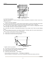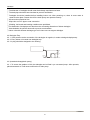
1
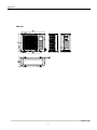
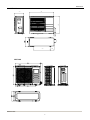
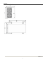
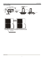
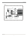
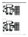
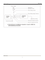
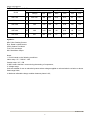
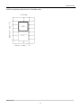
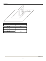
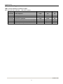
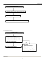
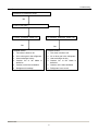
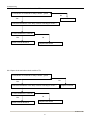
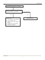
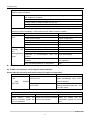
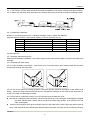
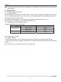
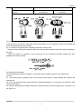
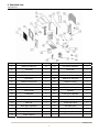
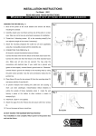
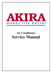
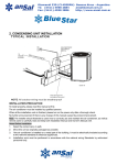
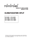
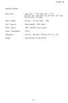
SERVICE MANUAL CONDENSING UNITS ASE-18A, ASE-24A ASE-36A, ASE-48A, ASE-60A Dimensions 1. Dimensions 12.5 ASE-18A Outdoor units 2 Dimensions ASE-24A 895 860 330 62 141 590 ASE-36A Outdoor units 3 Dimensions ASE-48A ASE-60A Outdoor units 4 Service space 2. Service Space Capacity≤60000Btu Obstacle >30cm Air inlet >30cm >60cm (Wall or obstacle) Air inlet Fix with bolt Maintain channel >200cm >60cm Air outlet Deep foundation Necessary width 600mm M10 bolt 4pieces per unit Outdoor units 5 Wiring diagrams ASE-24A BLACK FAN2 OUTDOOR UNIT WIRING DIAGRAM RED RED R S XT7 COMP KM8 RED C2 RED WHITE BLACK M BLUE CAP1 BLACK CODE COMP CAP1 C2 FAN2 XT3 XT4 XP1 XS1 RT3 XT7 KM8 XT2 Y/G C RT3 RED RED RED BLACK XP1 XS1 RED BLACK BLACK XT3 XT2 XT4 T3 E TO INDOOR UNIT Y/G 1 TO INDOOR UNIT 2 3 4 5 6 TO INDOOR UNIT Outdoor units 6 PART NAME COMP COMP CAP FAN CAP OUTDOOR FAN 5-WAY TERMINAL 6-WAY TERMINAL CONNECTORS CONNECTORS TEMP.SENSOR MID-TERMIANL CONTACTOR 3-WAY TERMINAL Wiring diagrams ASE-36A T5 RED(A1) BLACK(HI) RED(A1) XT5 RED BLACK CODE COMP FAN3 CT1 CN200 CN100 BLACK(L3) BLUE(N) 3 T R 4 T R CN201 BLACK(HI) RED(LOW) WIRING DIAGRAM CN203 CN208 MAIN CONTROL BOARD BLACK(L1) BLACK(L2) 88 PX S X 99 PX S X CN206 H-PRO K1 CAP3 BLACK(L1) KM1 A1 1 3 5 BLACK(L2) KM1 A2 2 4 6 T5 XT4 XT5、6 BLACK(L3) 21 22 FAN3 BLUE BLUE BLUE(N) BLACK(L3) BLACK(L2) W BLUE(N) Y/G BLACK(L1) U BLUE(N) CAP3 V COMP XT6 XT3 Y/G A B C N 1 2 3 4 AC CONTACTOR TRANSFORMER 4-WAY TERMINAL CONNECTOR H-PRO HIGH PRESSURE SWITCH CT1 CURRENT DETECTOR RT3 PIPE TEMP. SENSOR CONNECTORS CONNECTORS XP8-9 CN100-208 P.C.BOARD SOCKETS RED XT4 OUTDOOR FAN FAN CAP XS8-9 Y/G BLUE(N) PART NAME COMPRESSOR K1 TEMP. PROTECT SWITCH RT4 ROOM TEMP. SENSOR XT3 5-WAY TERMINAL TO INDOOR UNIT TO INDOOR UNIT ASE-48A ASE-60A T5 CN206 BLUE CN203 FAN3 FAN4 BLACK(L3) BLUE(N) BLACK(L2) BLACK(HI) RED(A1) WHITE CODE COMP CN200 CN100 RED(A1) 3 T R 4 T R CN201 BLACK(L1) 8S 8 P XX 9S 9 P XX MAIN CONTROL BOARD BLACK(HI) RED(LOW) XT5 WIRING DIAGRAM CN208 H-PRO K1 CAP3 CAP4 BLACK(L1) KM1 BLACK(L2) BLACK(L3) A1 1 3 5 A2 2 4 6 21 22 KM1 BLUE(N) BLUE(N) W BLACK(L3) BLACK(L2) COMP CAP3 XT6 WHITE YELLOW XT1 XT2 1 2 3 4 A B C N Y/G 5-WAY TERMINAL PIPE TEMP. SENSOR XS8-9 CONNECTORS CN100-208 RED BLUE CONNECTOR HIGH PRESSURE SWITCH RT3 XP8-9 Y/G BLUE(N) RED BLACK(L1) U BLUE(N) FAN4 TRANSFORMER 4-WAY TERMINAL XT1 V FAN CAP AC CONTACTOR XT2 H-PRO YELLOW RED OUTDOOR FAN T5 XT5、6 FAN3 PART NAME COMPRESSOR CONNECTORS P.C.BOARD SOCKETS K1 TEMP.PROTECT SWITCH RT4 ROOM TEMP. SENSOR CAP4 TO INDOOR XT2 TO INDOOR XT1 Outdoor units 7 Field wiring 4. Field Wiring Outdoor units 8 Electric characteristics 5. Electric Characteristics Units Model Compressor OFM Hz Voltage Min. Max. MSC RLA KW FLA ASE-18A 50 220~240 198 264 36.8 8.75 53 0.61 ASE-24A 50 220~240 198 264 61 11.4 53 0.66 ASE-36A 50 380 342 418 61 6.58 250 1.38 ASE-48A 50 380 342 418 66 8.22 65 0.7 ASE-60A 50 380 342 418 67 9.77 65 0.7 Symbols: MSC: Max. Starting Current RLA: Rated Locked Current OFM: Outdoor Fan Motor FLA: Full Load Amps. KW: Rate Motor Output Notes: 1. RLA is based on the following conditions: Indoor temp. 27℃ DB/19℃ WB Outdoor temp. 35℃ DB 2. MSC means the Max. current during the starting of compressor; 3. Voltage range Units are suitable for use on electrical systems where voltage supplied to unit terminals is not below or above listed range limits; 4. Maximum allowable voltage variation between phase is 2%; Outdoor units 9 Operation limits 6. Operation Limits Ensure the operating temperature is in allowable range. emp.(°C) Cooling 45 STD 35 Ambient 17 With low ambient temp. cooling module -7 17 24 30 Indoor temp.(°C) Outdoor units 10 Sound levels 7. Sound levels 1m Microphone Model Noise level(dB(A)) ASE-18A 48 ASE-24A 55 ASE-36A 57 ASE-48A ASE-60A 58 Outdoor units 11 Troubleshooting 9. Troubleshooting LEDs’ for the indication of outdoor trouble ASF-36A, ASF-48A, ASF-60A, 380-415V, 3 phase Type Contents LED1 LED2 LED3 Flash Off Off Off Off Flash Protection Phase sequence Protection Overload of current Protection Lack of phase Flash Off Off Protection Protection of pressure Flash Flash Off Protection Open-circuit and short-circuit trouble of T3 Off Flash Flash Protection Open-circuit and short-circuit trouble of T4 Off Flash Off Protection High temperature protection of condenser Flash Flash Flash Outdoor units 12 Troubleshooting 9.2.1 Phase sequence error: Phase sequence error Change the order of two of the wires to power supply. Switch on the unit again. If the problem can not be solved, the outdoor PCB is defective 9.2.2 Overload of current Overload of current Check the current, normally The max. current for ASF-36A is 9.4 A The max. current for ASF-48A is 10.9A The max. current for ASF-60A is 13.2A Is the current in rated range? No Yes The outdoor PCB is defective Possible reason 1. Outdoor fan is defective 2. The compressor is defective 3. Refrigerant is over charged 4. Air enter the refrigerant system 5. Heat exchanger is too dirty Outdoor units 13 Troubleshooting 9.2.3 Lack of phase Lack of phase Check the power supply, is it 3 phase, Yes Check the connection between power supply and terminal, Yes Outdoor PCB is defective Outdoor units 14 Troubleshooting 9.2.4 Protection of pressure or temp. Protection of pressure or temp. Yes Is it k1 or K2 open ? Is temp. protective switch K1 Is pressure protective switch K2 Yes Possible reason 1. The wires is loose to K1 2. Air or other gas in the refrigerant. 3. Heat exchanger is dirty 4. Outdoor fan or fan blade is defective 5. Outdoor unit is bad ventilation 6. Refrigerant is leakage Yes Possible reason 1. The wires is loose to K2 2. Air or other gas in the refrigerant. 3. Heat exchanger is dirty 4. Outdoor fan or fan blade is defective 5. Outdoor unit is bad ventilation 6. Refrigerant is two much Outdoor units 15 Troubleshooting 9.2.5 Open-circuit and short-circuit trouble of T3 Is connection to connector of temp. sensor good? No Yes Repair connector Check the resistance of the temp. sensor according to Annex 1 Is it the resistance is normal? No Yes Indoor PCB is defective. Replace the sensor 9.2.6 Open-circuit and short-circuit trouble of T4 Is connection to connector of temp. sensor good? No Yes Check the resistance of the temp. sensor according to Annex 1 Repair connector Is it the resistance is normal? Yes Indoor PCB is defective. No Replace the sensor Outdoor units 16 Troubleshooting 9.2.7 High temperature protection of condenser High temperature protection of condenser Check the resistance of the temp. sensor according to Annex 1, is it normal? No Yes Possible reason 1. Air or other gas in the refrigerant. 2. Heat exchanger is dirty 3. Outdoor fan or fan blade is defective 4. Outdoor unit is bad ventilation 5. Refrigerant is leakage Replace the sensor Outdoor units 17 Troubleshooting 9.3 Troubles and Solutions If any the following abnormal conditions occur, turn off the power supply immediately. Please contact our dealer. TROUBLES Indicator lamps flash rapidly, after your disconnecting and connecting the unit, the situation is the same. Fuse or circuit breaker work frequently. Foreign matter or water has fallen into the unit. Remote controller is disabled or the switch is out of hand. Any other unusual conditioner is observed. If any of the following conditions occur, check your unit and resolve corresponding problems referring to given remediation. If the trouble can't be settled contact our dealer. Trouble Unit does not start Air flowing normally with low cooling(heating) effect Cause Solutions Power failure. Wait for the comeback of power Power switch is open. Switch on the power Fuse of power switch may have blown. Replace the fuse Batteries of remote controller are exhausted. Replace the batteries The time is not start-up time you have set. Wait or cancel the time set. Temperature is not set correctly. Set the temperature properly. Door or window is open. Close door and window. Air filter is blocked with dust or dirtiness. Clean the air filter. Inlet/outlet blocked. of indoor/outdoor units are Clear all blockages. Inlet/outlet blocked. of indoor/outdoor units are Clear the blockage, then restart your operation. Be in 3 minutes protection of compressor Wait NOTE: Do not replace electric wire or repair the air conditioner by yourself to avoid possible danger. 9.4 Troubles and solutions concerning the remote controller Please make the following check before asking for repair or maintenance. Trouble Cause Solutions CAN NOT CHANGE THE FAN SPEED SETTING Check if the mode display on the LCD is AUTO The lndoor Unit will select fan speed automatically when AUTO mode is selected. Check if the mode display on the LCD is DRY The lndoor Unit will select fan speed automatically when the unit is on DRY mode. The transmission symbol does not flash Symptom Checking items Cause Press ON/OFF button, the remote controlling signals can not be transmitted Check if the remote controller has run out of power When the battery was out, transmission signals can not be sent Outdoor units 18 MCAC-UTSM-2006-12 Troubleshooting Temperature display disappear Symptom Checking items Temperature Display does not light. Check if the mode display on the LCD is FAN ONLY Cause You can not set the temperature when the unit is on FAN ONLY mode. The Display Goes Off Symptom Checking items Cause The indication on the display disappears after a lapse of time. Check whether the timer operation has come to an end when the OFF TIMER is indicated on the display. The air conditioner operation stops since the set time elapsed. The ON TIMER indicators go off after a lapse of certain time. Check whether the timer operation is started when the ON TIMER is indicated on the display. When the time set to start the air conditioner is reached, the air conditioner will automatically start and the appropriate indicator will go off. The Signal Receiving Tone does Not Sound Symptom Checking items Cause No receiving tone sounds from the indoor unit even when the ON/OFF button is pushed. Check whether the signal transmitter of the remote controller is properly directed to the receiver of the indoor unit when the ON/OFF button is pushed. Direct the signal transmitter of the remote controller to the receiver of the indoor unit, and then repeatly push the ON/OFF button twice. Buttons on the remote controller don't work. Press Reset button. 91 Outdoor units 19 Installation Installation Installation 20 Installation 1. Refrigerant pipe installation 1.1. Measure the necessary length of the connecting pipe, and make it by the following way. a. Connect the indoor unit at first, then the outdoor unit. Bend the tubing in proper way. Do not harm them. CAUTIONS: z Daub the surfaces of the flare pipe and the joint nuts with frozen oil, and wrench it for 3~4 rounds z With hands before fasten the flare nuts. Be sure to use two wrenches simultaneously when you connect or disconnect the pipes. Tubing size Torque 6.35 1420~1720N.cm(144~176kgf.cm) 9.52 3270~3990N.cm(333~407kgf.cm) 12.7 4950~6030N.cm(504~616kgf.cm) 16 6180~7540N.cm(630~770kgf.cm) 19 9720~11860N.cm(990~12106kgf.cm) b. The stop value of the outdoor unit should be closed absolutely (as original state). Every time you connect it, first loosen the nuts at the part of stop value, then connect the flare pipe immediately (in 5 minutes). If the nuts have been loosened for a long time, dusts and other impurities may enter the pipe system and may cause malfunction later. So please expel the air out of the pipe with refrigerant before connection. c. Expel the air after connecting the refrigerant pipe with the indoor unit and the outdoor unit. Then fasten the nuts at the repair-points. 1.2. Locate The Pipe a. Drill a hole in the wall (suitable just for the size of the wall conduit), then set on the fittings such as the wall conduit and its cover. b. Bind the connecting pipe and the cables together tightly with binding tapes. Do not let air in, which will cause water leakage by condensation. c. Pass the bound connecting pipe through the wall conduit from outside. Be careful of the pipe allocation to do no damage to the tubing. 1.3. Connect the pipes. 1.4. Then, open the stem of stop values of the outdoor unit to make the refrigerant pipe connecting the indoor unit with the outdoor unit in fluent flow. 1.5. Be sure of no leakage by checking it with leak detector or soap water. 1.6. Cover the joint of the connecting pipe to the indoor unit with the soundproof / insulating sheath (fittings), and bind it well with the tapes to prevent leakage. 2. Vacuum dry and leakage checking 2.1. Vacuum Dry: use vacuum pump to change the moisture (liquid) into steam (gas) in the pipe and discharge it out of the pipe to make the pipe dry. Under one atmospheric pressure, the boiling point of water(steam temperature) is 100℃. Use vacuum pump to make the pressure in the pipe near vacuum state, the boiling point of water falls relatively. When it falls under outdoor temperature, the moisture in the pipe will be vaporized. Installation 21 Installation 2.2. Vacuum dry procedure There are two methods of vacuum dry due to different construction environment: common vacuum dry, special vacuum dry. ①. Common vacuum dry procedure z Vacuum dry (for the first time)---connect the all-purpose detector to the inlet of liquid pipe and gas pipe, and run the vacuum pump more than two hours (the vacuum pump should be below -755mmHg) z If the pump can’t achieve below -755mmHg after pumping 2 hours, moisture or leakage point will still exist in the pipe. At this time, it should be pumped 1 hour more. z If the pump can’t achieve -755mmHg after pumping 3 hours, please check if there are some leakage points. z Vacuum placement test: place 1 hour when it achieves -755mmHg, pass if the vacuum watch shows no rising. If it rises, it shows there’s moisture or leakage point. z Vacuuming from liquid pipe and gas pipe at the same time. z Sketch map of common vacuum dry procedure. ② Special vacuum dry procedure z This vacuum dry method is used in the following conditions: There’s moisture when flushing the refrigerant pipe. Rainwater may enter into the pipe. z Vacuum dry for the first time ······ 2h pumping ③. Vacuum destroy for the second time ······ Fill nitrogen to 0.5Kgf/cm2 Because nitrogen is for drying gas, it has vacuum drying effect during vacuum destroy. But if the Installation 22 Installation moisture is too much, this method can’t dry thoroughly. So, please pay more attention to prevent water entering and forming condensation water. ④. Vacuum dry for the second time······1h pumping Determinant: Pass if achieving below -755mmHg. If -755mmHg can’t be achieved in 2h, repeat procedure ③ and ④. ⑤. Vacuum placing test ······ 1h ⑥. Sketch map of special vacuum dry procedure 3. Additional charge 3.1. When the length of the one-way pipe is less than 5m, additional refrigerant charge after vacuuming is unnecessary. 3.2. When the length of one-way pipe is over 5m, the additional charge quantity is as follows (unit in gram): Calculation method Refrigerant R410A Liquid diameter(mm) Unit amount (g/m) Formula Φ6.35 30 (L-5)×22 Φ9.53 65 (L-5)×60 Φ12.7 90 (L-5)×110 Remark:1、The additional refrigerant charge is simply related with the liquid pipe diameter. 2、In the up formula, “L” means total length of liquid pipe(unit: m). 4. Water drainage 4.1. Gradient and Supporting 4.1.1 Keep the drainpipe sloping downwards at a gradient of at least 1/100. Keep the drainpipe as short as possible and eliminate the air bubble. 4.1.2 The horizontal drainpipe should be short. When the pipe is too long, a prop stand must be installed to keep the gradient of 1/100 and prevent bending. Refer to the following table for the specification of the prop stand. Hard PVC pipe Diameter Distance between the prop stands 25~40mm 1.5~2m Installation 23 Installation 4.1.3. Precautions ① The diameter of drainpipe should meet the drainage requirement at least. ② The drainpipe should be heat-insulated to prevent atomization. ③ Drainpipe should be installed before installing indoor unit. After powering on, there is some water in water-receiver plate. Please check if the drain pump can operate correctly. ④ All connection should be firm. ⑤ Wipe color on PVC pipe to note connection. ⑥ Climbing, horizontal and bending conditions are prohibited. ⑦The dimension of drainpipe can’t less than the connecting dimension of indoor drainpipe. ⑧ Heat-insulation should be done well to prevent condensation. ⑨Indoor units with different drainage type can’t share one convergent drainpipe. 4.2 Drainpipe Trap 4.2.1. If the pressure at the connection of the drainpipe is negative, it needs to design drainpipe trap. 4.2.2. Every indoor unit needs one drainpipe trap. 4.2.3. A plug should be designed to do cleaning. 50cm 50cm Plug 4.3 Upwards drainage(drain pump) 4.3.1. To ensure the gradient 1/100, the drainpipe can be lifted it you use water lpump. After upwards, place downwards or it will cause malfunction to drain pump. Installation 24 Installation 4.4 Convergent drainage 4.4.1. The number of indoor units should be as small as possible to prevent the traverse main pipe overlong. 4.4.2. Indoor unit with drain pump and indoor unit without drain pump should be in different drainage system. 4.4.3. Selecting the diameter Number of connecting indoor units→Calculate drainage volume→Select the diameter Calculate allowed volume =Total cooling capacity of indoor units(HP)×2 (l/ hr) Hard Hard Hard Hard Hard Allowed volume(lean 1/100) ∽≤14 14<∽≤88 88<∽≤334 175<∽≤334 334<∽ (l/ hr) I.D. (mm) ¢25 ¢30 ¢40 ¢50 ¢80 Thick 3.0 3.5 4.0 4.5 6.0 4.5 Drainage test 4.5.1 Drainage without drain pump After finishing drainpipe installation, pour some water into the water receiver plate to check if the water flows smoothly. 4.5.2 Drainage with drain pump 4.5.2.1 Poke the Water Level Switch , remove the cover, use water pipe to pour 2000ml water into the water receipt plate through the water inlet. 4.5.2.2 Turn on the power to Cooling operation. Check the pump’s operation and switch on the Water Level Switch. Check the pump’s sound and look into the transparent hard pipe in the outlet at the same time to check if the water can discharge normally. 4.5.2.3 Stop the air conditioner running, turn off the power, and put back the cover. z Stop the air conditioner. After 3 minutes, check if it has abnormity. If the collocation of drainpipes is illogical, the water will flow back overfull, which will cause the alarm lamp flashes, even overflow from the water receipt plate. z Keep on pouring water until it gives an alarm signal for high water level, check if the pump drains water at once. If the water level can’t fall below the alarmed water level after 3 minutes, the air conditioner will stop. Installation 25 Installation Turn off the power and drain the remained water, then turn on the air conditioner. Note: The drain stuff in the main water receipt plate is for maintenance. Stuff up the drain stuff to prevent water leakage. 5. Insulation work 5.1 Insulation material and thickness 5.1.1. Insulation material Insulation material should adopt the material which is able to endure the pipe’s temperature: no less than 70℃ in the high-pressure side, no less than 120℃ in the low-pressure side(For the cooling type machine, no requirements at the low-pressure side.) Example: Heat pump type----Heat-resistant Polyethylene foam (withstand above 120℃) Cooling only type---- Polyethylene foam (withstand above 100℃) 5.1.2. Thickness choice for insulation material Insulation material thickness is as follows: Refrigerant pipe Drainage pipe Pipe diameter (mm) Adiabatic material thickness Φ6.4—Φ25.4 10mm Φ28.6—Φ38.1 15mm Inner diameterΦ20—Φ32 6mm 5.2 Refrigerant pipe insulation 5.2.1. Work Procedure ① Before laying the pipes, the non-jointing parts and non-connection parts should be heat insulated. ② When the gas proof test is eligible, the jointing area, expanding area and the flange area should be heat insulated 5.2.2. Insulation for non-jointing parts and non-connection parts Installation 26 Installation wrong Gas pipe and liquid pipe should right Insulate the gas pipe (cooling only) Insulate the gas pipe and liquid pipe For construction convenience, before laying pipes, use insulation material to insulate the pipes to be deal with, at the same time, at two ends of the pipe, remain some length not to be insulated, in order to be welded and check the leakage after laying the pipes. 5.2.3. Insulate for the jointing area, expanding area and the flange area ① Insulate for the jointing area, expanding area and the flange area should be done after checking leakage of the pipes ② Make sure there’s no clearance in the joining part of the accessorial insulation material and local preparative insulation material. 5.3 Drainage pipe insulation The connection part should be insulated, or else water will be condensing at the non-insulation part. 5.4 Note 5.4.1 The jointing area, expanding area and the flange area should be heat insulated after passing the pressure test 5.4.2 The gas and liquid pipe should be heat insulated individually, the connecting part should be heat insulated individually. 5.4.3 Use the attached heat-insulation material to insulate the pipe connections (pipes’ tie-in ,expand nut ) of the indoor unit Installation 27 PARTS GUIDE CONDENSING UNITS ASE-18A, ASE-24A ASE-36A, ASE-48A, ASE-60A 8. Exploded view Exploded view ASF-18A No. Part Name Quantity No. Part Name Quantity 1 Clamp for front net 8 18 Fan motor capacitor 1 2 Front net 1 19 Wire joint 1 3 Front clapboard 1 20 Separating board 1 4 Propeller fan 1 21 Installation board for E-parts 1 5 Fan motor 1 22 Washer for wire joint 1 6 Holder for fan motor 1 23 Clamp for wiring 1 7 Foam over holder for motor 1 24 Compressor capacitor 1 8 Cover 1 25 Capacitor clamp 1 9 Little handle 1 26 Chassis 1 10 Condenser 1 27 Front right clapboard 1 11 Support board for motor holder 1 28 Compressor 1 12 Left clapboard 1 29 Liquid valve assy 1 13 Rear net 1 30 Liquid pipe valve 1 14 Rear right clapboard 1 31 Gas pipe valve 1 15 Big handle 1 32 Copper nut, TLM-A01 1 16 Installation plate for valves 1 33 Copper nut, TLM-C03 1 17 Water collector 1 Outdoor units 2 Exploded view ASF-24A No. Part Name Quantity No. 1 Front net 1 2 Cabinet,Front 1 3 Fan,Propeller 1 19 1 20 1 21 1 22 1 23 4 Fan Motor 5 Mount,Fan 6 Topcap 7 Condenser Motor Ass'y Ass'y 18 Part Name Quantity Washer for wire joint 1 Terminal install board 1 Terminal 1 Block,2p AC contactor Capacitor,Fan Wire Terminal 1 Motor Clamp 1 1 Block,5p 1 8 Inlet Pipe for Condenser 1 24 Compressor 1 9 Outlet Pipe for Condenser 1 25 Fixture,Segregator 1 1 26 Liquid pipe valve 1 10 Rear Net 11 Support board,Back side 1 27 Capillary pipe 1 12 Handle 2 28 Gas pipe valve 1 13 Separating board 1 29 refrigerant Container 1 1 30 14 Base Pan Ass'y Support board, Left Side 1 15 Cabinet,Front-Right 1 31 Big handle 1 16 Capacitor 1 32 Small Handle 1 1 33 Copper nut, TLM-B02 1 1 34 Copper nut, TLM-D04 1 17 18 Clamp Capacitor, Compressor Wiring Installation Panel Outdoor units 3 Exploded view ASF-36A No. Part Name Quantity No. Part Name Quantity 1 Clamp for front net 10 19 Container clamp 1 2 Front net 2 20 Fan motor capacitor 1 3 Front clapboard 1 21 Installation board for E-parts 1 4 Propeller fan 1 22 AC contactor 1 5 Fan motor 1 23 Main control board,Outdoor unit 1 6 Holder for fan motor 1 24 Wire joint for multiplexer 2 7 Chassis 1 25 Wire joint for multiplexer 1 8 Separating board 1 26 Washer for wire joint 1 9 Cover 1 27 Wire clamp 1 Condenser I 1 28 Wire joint for power 1 Condenser II 1 29 Liquid valve assy 1 11 Support board for motor holder 1 30 Liquid valve 1 12 Left supporting bar 1 31 Gas valve 1 13 Rear net 1 32 Compressor 1 14 Rear right clapboard 1 33 Discharge temp sensor 1 15 Big handle 1 34 Front right clapboard 1 16 Installation plate for valves 1 35 Copper nut, TLM-C03 1 17 Pipe temp sensor 1 36 Copper nut, TLM-E05 1 18 Refrigerant container 1 10 Outdoor units 4 Exploded view ASF-48A No. Part Name Quantity No. Part Name Quantity 1 Front net 2 15 Cabinet,Front Side 1 2 Cabinet,Front 1 16 E-control box, assy 1 3 Fan,Propeller 2 17 2 18 1 19 AC contactor 1 1 20 Low Pressure Valve 1 1 21 PCB board,outdoor unit 1 Condensator I 1 22 Terminal Block,3p 1 Condensator II 1 23 Wire joint for power 1 9 Left Side Cabinet 1 24 Compressor 1 10 Supporter, Rear Cabinet 1 25 10 Supporter, Rear Cabinet 1 26 Fixture,Segregator 1 1 27 Low Pressure Valve 1 4 5 Fan Motor Room temp. sensor,outdoor 6 Mount,Fan 7 Topcap 8 Motor Ass'y Terminal Refrigerator Motor Block,2p Container 2 3 1 11 Cabinet,Back 12 Handle 2 28 13 Plate,Sound-proof 1 29 Discharge temp controller 1 1 30 Pipe temp. sensor 1 14 Base Pan side Capacitor,Fan Ass'y Capillary Tube Ass'y 1 Outdoor units 5 Exploded view ASF-60A No. Part Name Quantity No. Part Name 1 Front net 2 15 2 Cabinet, Front 1 16 3 Fan, Propeller 2 17 2 18 1 19 AC contactor 1 1 20 Low Pressure Valve 1 1 21 PCB board, outdoor unit 1 Condensator I 1 22 Terminal Block,3p 1 Condensator II 1 23 Wire joint for power 1 9 Left Side Cabinet 1 24 Compressor 1 10 Supporter, Rear Cabinet 1 25 10 Supporter, Rear Cabinet 1 26 Fixture, Segregator 1 11 Cabinet, Back side 1 27 Low Pressure Valve 1 12 Handle 2 28 Capillary Tube Ass'y 1 13 Plate, Sound-proof 1 29 Discharge temp controller 1 1 30 Pipe temp. sensor 1 4 5 Fan Motor Room temp. sensor, outdoor 6 Mount, Fan 7 Topcap 8 14 Base Pan Motor Ass'y Ass'y Outdoor units 6 Cabinet, Front Side Quantity E-control box, assy Capacitor, Fan Terminal Refrigerator Motor Block,2p Container 1 1 2 3 1