1
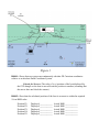
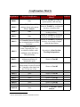
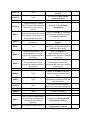
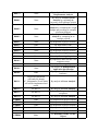
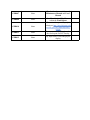
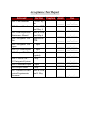
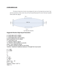
LPARD-TDF-2012
Lafayette Programmable
Autonomous River Droid
Tracking and Data Fusion
ECE492 - Spring 2012
Acceptance Test Plan
Last Revision Date 3/5/2012 by David Salter
Table of Contents
Table of Contents
Purpose
Acceptance Testing
Acceptance Test T001 - Sensor Fusion:
Acceptance Test T002 - SCADA
Acceptance Test T003 - Demo App
Detailed System Requirements
R000: Position and Heading Estimates
R001: Operational Swath
R002: System Control and Data Acquisition
R003: Autonomous Mode and Manual Override
R004: Control Modes
R005: Data Link
R006: User Interface
R007: Environmental
R008: Payload
R009: API and SDK
R010: Demonstration Application
R011: Power Input Independence
General Project Requirements
GPR001: Documentation
GPR002: Environmental
GPR003: EMI/EMC
GPR004: Hazmats
GPR005: Safety and Good Practice
GPR006: Reliability
GPR007: Maintainability
GPR008: Manufacturability
GPR009: Life Cycle Sustainability
GPR010: Ethics
GPR011: Project Demonstration
GPR012: Final Disposal of Projects
Confirmation Matrix
Acceptance Test Report
Purpose
To ensure that our designed system meets all the requirements as specified in
the LPARD-TDF-2012 Statement of Work, this document will provide the tests and
measurements that will be carried out to prove the system meets requirements. Each test
will outline a testing scenario that provides the materials needed and location where the
test is to be executed. Included with each test will also be a procedure and a specific list
of requirements that the test will verify.
Acceptance Testing
Acceptance Test T001 - Sensor Fusion:
This test verifies the following requirements:
● R000-1,2,3
● R001-1,2,3
● R005-2
Required Materials:
● Tripods (2x for mounting sensors)
● Pair of Surveying Tripods
● Laptop
● Extension cord (2x 25’,1x 50’ 1x 100’)
● 18V AC Adaptor (3x)
● Power Strip (1x with at least 5 slots)
● Surveying Stand
● Tape Measure (length of 50’ or greater)
● Fold up table to place laptop on.
● 5m CAT6 cable (2x)
● Sensor Circuitry to be mounted on tripod (2x)
● USB hub and two I2C converters
● Masking Tape to mark locations on ground
● Laptop charger (precautionary)
Procedure:
1. Take all required equipment out to the Watson Quad.
2. Plug in a 50’ extension cord to wall outlet inside Acopian doors and plug a power
3.
4.
5.
6.
strip to the end.
Set up table and laptop with USB hub next to power strip.
Turn on laptop, plug laptop charger (if laptop battery is low) to the power-strip,
and start GUI program by double clicking the icon on the desktop.
Attach sensor circuitry to tops of tripods (following instructions in final User’s
Manual) and set up each tripod at approximately the same height (~ four feet).
Plug in two 25’ extension cords to power strip and attach 18V Adapter to the end
of each. Plug an 18V adapter to the power jack on each sensor tripod.
7. Connect an I2C wire from each AZ/EL sensor to the USB converter plugged into
the laptop’s USB hub.
8. Connect 100’ extension into power strip with 18V adapter to end and plug into the
boat’s power jack.
9. Set up two tripods approximately 10 meters apart from one another (directly
facing each other) and measure the exact distance from ultrasound sensor to
ultrasound sensor using the tape measure.
10. Enter the actual distance measured into the “Baseline Sensor Distance” field in the
calibration screen of the GUI program (first window that pops up).
11. Press the “Calibrate button”.
12. Rotate the tripods in their current position so that the sensors face perpendicular to
the baseline distance (facing out towards “river area”).
13. Place a piece of masking tape at position approximately half way between the two
tripods and a distance of approximately two meters from the baseline distance (this
will represent the origin point of our local coordinate system).
14. Place one surveying stand so that it is centered on this origin.
15. Place the other surveying stand approximately at the positions marked by the red
dots on Figure 1 below. Once each position is measured, record the actual x and y
position and place a piece of tape on the ground to mark the position.
16. After each location has been marked, turn the power switch on the boat so that the
boat is powered on and move the boat to the marked locations (place the boat on
the ground with the lighting beacon directly on top of the tape and the ultrasonic
sensor facing the center of the two beacons).
17. Allow boat to sit at each position so that the SCADA program can log at least 10
(x,y) positions of the boat. Use these 10 data points to compute the RMS (x,y)
position of the boat.
Diagram of Test001
Scenario
Figure 1
R000-1: Shows that our system can continuously calculate 2D Cartesian coordinates
relative to an absolute Earth Coordinate System.
Criteria for Success: The value of (x,y) position of the boat displayed by
the GUI changes as the boat is moved from one position to another (assuming that
the mover does not block the sensors).
R000-2: Show that the calculated position of the boat is accurate to within the required
10 cm RMS value.
Position P1:
Position P2:
Position P3:
Position P4:
Position P5:
Displayed ____________
Displayed ____________
Displayed ____________
Displayed ____________
Displayed ____________
Actual RMS ____________
Actual RMS ____________
Actual RMS ____________
Actual RMS ____________
Actual RMS ____________
Criteria for Success: The IR sensor successfully detects angles in azimuth
and elevation within 0.5 degrees RMS. The ultrasound sensors successfully detect
range within 14 cm RMS. These are based off of the logged raw sensor data from
points P1-P5.
Criteria for Success: The total RMS position for (P1 through P5) is within
the RMS value accepted by R000 (20 cm proposed). Based on the equations
below.
R000-3: Shows the system is capable of providing continuous heading updates by
comparing reported values to known values.
Position P1:
Position P2:
Position P3:
Position P4:
Position P5:
Displayed ____________
Displayed ____________
Displayed ____________
Displayed ____________
Displayed ____________
Actual RMS ____________
Actual RMS ____________
Actual RMS ____________
Actual RMS ____________
Actual RMS ____________
Criteria for Success: The heading values provided are accurate to within
0.25 degrees RMS at up to 25 meters.
R001-1: Position estimates are accurate to values specified in R000-2 and R000-3 over a
0 to 25 meter range.
Criteria for Success: If the positions measured in R000-2 are within the
proposed value (analysis given in the document Error Analysis), and the QA tests
for both the IR and Ultrasound sensors pass for range detection out to 25 meters
(QA Tests are provided in: Sound Sensors Specification Document and IR
Sensor Specification, then it is inferred that the the measurements are successful
to within 25 meters. (Error Analysis document takes the QA requirements for IR
and Ultrasound subsystems and generates errors out to 25 meters).
R001-2: Position estimates are accurate to values specified in R000-2 and R000-3 over a
± 90 degree in azimuth from the shore station.
Criteria for Success: Points P1 and P5 labeled in Figure 1 (if placed at
the labeled positions), shows a ~ ±83 degree operational swath. If points P1 and
P5 are measured successfully in R000-2, then these points therefore meet the
operational swath requirements.
R001-3: Degraded accuracy shall be possible over a swath out to 200 meters in range.
Criteria for Success: As long as the GPS is sending data to the GUI
program over the laptop via the RF link, we will have “degraded accuracy”
by means on the GPS position. The requirement is therefore successful if the
GUI program on the laptop displays the GPS value and the provided analysis
(shown in document RF Distance Analysis) shows that our RF link is capable of
communicating over 200 meters (200m QA test for RF is impractical).
GPS value displayed on GUI (yes/no) _________
R005-2: Data link does not interfere with signals used for positioning.
Criteria for Success: Success criteria for R000-2 and R000-3 have been met as there is position data being transmitted to the boat (shore sensors) and to the
shore (fused position), meeting those requirements implies the data link does not
interfere.
Acceptance Test T002 - SCADA
Requirements Verified:
● R002-1, 2, 4, 6, 7, 8, 9, 13
● R003-1
● R004-2, 3, 4
● R005-1
● R006-1, 2
Required Materials:
● AEC Room 400
● At least two test engineers
● Laptop with USB port running LPARD software
Laptop AC power cable
LPARD Shore Interface box, complete with antenna and USB cable
LPARD Boat Hardware, complete with sensors and antenna
Desktop Computer with USB port running Arduino software
USB to miniUSB cable
USB to USB cable
2 18V AC Adapter
Arduino Mega 2560 with Dummy Sensor firmware
Custom RJ45 to Arduino adapter (Cut open CAT6 cable with pins for the
appropriate signals)
● Power Supply with power cable.
●
●
●
●
●
●
●
●
●
Procedure:
1. Bring all required materials to AEC400.
2. Read the User Manual.
3. Set the laptop, LPARD Shore Interface box, Arduino, and Power Supply on center
table.
4. Plug in laptop power cable into laptop and into wall power.
5. Plug 18v AC converter into LPARD Shore Interface box and into wall power.
6. Plug power supply into wall power.
7. Plug LPARD Shore Hardware USB cable into laptop.
8. Plug Arduino into laptop using USB to USBb cable.
9. Connect power and ground on power supply to A0 and GND, respectively, on the
Arduino.
Plug LPARD Interface box into the SDA and SCL ports of the Arduino
10.
using the Custom RJ45 to Arduino adapter.
Place LPARD Boat Hardware on lab desk near whiteboard.
11.
Open Boat Microcontroller access on LPARD Boat Hardware box
12.
Plug Boat Microcontroller into desktop computer using USB to miniUSB
13.
cable.
Open a terminal to view the output of the Boat Hardware serial output one
14.
of two ways:
a. Open arduino.exe, select COM8, and press the Serial Monitor button.
b. Open X-CTU, select COM8, and click the Terminal tab.
Turn on laptop.
15.
Start the LPARD software.
16.
Enter user name as “Test002” and location as “AEC400”.
17.
Enter baseline distance as 1m in prompt and hit OK.
18.
Turn on boat and hit Calibrate. The GUI will open.
19.
Have one test engineer move position of boat and look for constantly
20.
updating boat status data on GUI. At the same time, have another test engineer
change the Power Supply output voltage and look for changes on the terminal
display connected to the Boat Hardware.
Continue step 20 for about one minute.
21.
Change the control mode from Autonomous Freeze (the default) to
22.
Autonomous Ferry and verify that a Ferry input can be entered and the system logs
the command.
Change the control mode back to Autonomous Freeze and verify that a
23.
Ferry input can no longer be entered and the system logs the command.
Click on the “Script” button and input a combination of freezes and ferries
24.
in the specified input and verify that the script runs (the commands are displayed
in the system log).
Set the x-axis to x-position and the y-axis to y-position and verify that the
25.
graph correctly displays the updating x vs y position and the compass shows the
heading.
Navigate to log file directory on laptop and verify that data from the test
26.
session has logged correctly for: each sensor, initial polar to Cartesian position
conversion, fused position value, and the system commands and faults.
Power down the boat’s micro-controller and verify that the boat is no
27.
longer connected to the system and both the GUI and the log file for the system
log this fault.
Once finished, power down the boat, then close the program, then power
28.
down the laptop.
R002-1: Show SCADA supports all the operating and maintenance modes.
Criteria for Success: Success will be determined if the system runs
properly throughout the test and all of the mode changes.
R002-2: Show SCADA serves as the Operation User Interface for autonomous control..
Criteria for Success: Success will be determined if the autonomous mode
can be changed from Ferry to Freeze and back again and a script (combination of
ferry and freezes) can be run with all of the mode changes logged in the system
log.
R002-4: Show SCADA UI allows a trained human technician to easily control and
monitor the processes.
Criteria for Success: Ease of control shall be affirmed by correlating
controllable UI fields to a correctly outlined procedure for use in the user manual.
Success of monitoring the process shall be determined by the numerical and
graphical display of all relevant data being logged.
R002-6: Show the following parameters are monitored and stored by SCADA: boat
position and orientation, raw position sensor data, hydrology sensor data, voltage,
current, and power delivered by power supplies, subsystem temperatures, and operational
state.
Criteria for Success: Success will be determined if a separate and accurate CSV
file with session data has been created for: each sensor, initial position fusion from
polar to Cartesian, and completely fused position displayed in the GUI.
R002-8: Show plots over specified parameter ranges can be generated by the user.
Criteria for Success: Success will be determined if throughout the test, the
plot continuously updates dependant on the axis selections.
R002-9: Show the SCADA logs commands, events, exceptions, faults, and operation
state changes.
Criteria for Success: Success will be determined if the system log has been
generated for the test session. The program will log all data displayed in the GUI
under system output which will contain all the parameters listed above. Additional
information may be logged and should not preclude success of this requirement
being demonstrated.
R002-13: Show the SCADA can automatically log an event, enable an alarm, and declare
a fault to shutdown the system.
Criteria for Success: Success will be determined if the fault tested is
affirmed in the system log and displayed on the GUI..
R003-1: Show the LPARD includes an autonomous closed loop controller that interfaces
with the shore based RC link for propulsion and maneuvering.
Criteria for Success: Simulate ability to close loop, without
implementation on the micro-controller.
R004-2: Show freeze mode can be supported by the existing software.
Criteria for Success: Success will be determined by the successful system
logging of freeze mode.
R004-3: Show ferry mode can be supported by the existing software.
Criteria for Success: Success will be determined by the successful system
logging in ferry mode.
R004-4: Show script mode can be supported by the existing software.
Criteria for Success: Success will be determined by the successful system
logging of the script that is run.
R005-1: Show full-duplex communication by having real time data appear on both sides
of the RF link at the same time.
Criteria for Success: During step 18, real time data appeared on the GUI
and the Terminal display.
R006-1: Show real time display of relevant information.
Criteria for Success: Success will be determined if the GUI implements
R006-2 at the rate of data recording, which by default will be once per second.
R006-2: Show both numeric and graphical representations.
Criteria for Success: Success will be determined by the presence of a
graphical representation of data in the GUI, with changeable axes to display any
possible data. GUI will also have a field allocated for sensors on the boat, and
a field for payload sensors. Each will contain numerical representations of any
sensor listed.
Confirmation Matrix
Requirement
Proposed Modification
Confirmation
Method1
R000-1
None
Shown in Test 001 by noting the
system updates while moving.
R000-2
10 cm RMS to 20 cm RMS.
Analysis shown in document
Error Analysis
R000-3
None
R001-1
None
R001-2
R001-3
R002-1
R002-2
R002-3
R002-4
R002-5
R002-6
R002-7
R002-8
R002-9
R002-10
Shown in Test 001 by verifying the
accuracy of position data.
Shown in Test 001 by verifying the
heading accuracy.
Shown in Test 001 by examining
accuracy at a range of distances.
Proposed change to ±80 degrees
Shown in Test 001 by examining
with Omnidirectional Proposal
accuracy over a range of angles
due to azimuth limits of AZ/EL
from the base station.
Positioner.
Proposed change to
define “degraded past 25 m”
By analysis in Boat Position
as within an absolute earth
Tracking Independence
coordinate system defined by
GPS positioning.
Proposed change to only
implement operation in
Shown in Test 002
maintenance mode
Proposed change to have manual
control turned on and off from an
Shown in Test 002
RC Controller rather than from
the GUI for ease of use
None
By inspection
None
Shown in Test 002
None
By inspection
None
Shown in Test 002
None
Shown in Test 002
None
Shown in Test 002
None
Shown in Test 002
By analysis in Lifetime Capacity
None
Analysis
1 All tests and documents used for confirmation in bold.
Achieved
R002-11
None
R002-12
None
R002-13
R002-14
R003-1
R003-2
R004-1
R004-2
R004-3
R004-4
R005-1
R005-2
R005-3
R006-1
R006-2
R006-3
R007-1
R007-2
By analysis in Expandability
Analysis
By analysis in Data Storage
Format Analysis
Shown in Test 002
None
Proposed change to writing
specifications for the software
By memo in Aural Signal
and hardware that would be
Specification
needed
Proposed replacement with
Shown in Test 002 by examining
showing that control loop can be
boat hardware outputs in response
implemented once actuators are
to transmitted commands.
integrated into the system
Proposed replacement with a
By analysis in Manual Control
specification
Analysis
By inspection the code contains
None
the ability to manipulate motors to
handle the three modes.
Proposed replacement with
Shown in Test 002 by
showing that the SCADA
demonstration of necessary
supports the implementation of commands and data flow within the
this feature
control loop
Proposed replacement with
Shown in Test 002 by
showing that the SCADA
demonstration of necessary
supports the implementation of commands and data flow within the
this feature
control loop
None
Shown in Test 002
Shown in Test 002 by showing
None
real-time data transferred both
ways.
Shown in Test 001 by inspection of
None
simultaneous operation of RF link
and positioning.
By memo detailing end user
None
responses on necessary data speeds
None
Shown in Test 002
None
Shown in Test 002
None
By inspection of the GUI
Since we are not implementing
the final boat packaging, this
By analysis in Environmental
requirement should not be
Requirements Analysis
applicable.
By analysis in Environmental
See proposed change in R007-1.
Requirements Analysis
R007-3
None
R008-1
None
R008-2
None
R008-3
None
R009-1
R009-2
R009-3
R009-4
R010-1
R010-2
None
None
None
None
None
None
R010-3
None
R010-4
None
R010-5
None
R010-6
None
R011-2
Proposed replacement
with analysis, though
AC “Maintenance Power Mode”
will still be implemented and
tested.
See R011-1
R011-3
See R011-1
R011-4
GPR001
GPR002
GPR003
GPR004
GPR005
See R011-1
None
None
None
None
None
GPR006
None.
R011-1
By analysis in Environmental
Requirements Analysis
By analysis in Boat Payload
Analysis by explaining the
necessity of all hardware on boat
By analysis in Boat Payload
Analysis by examining the weight
budget and providing an example
placement diagram
By analysis in Boat Payload
Analysis by comparing to an
example payload
By inspection on project website.
By inspection of code.
By inspection on project website.
By inspection on project website.
Shown by Demo App Inspection.
Shown by Demo App Inspection.
By inspection, demo will use a full
computer screen.
Shown by Demo App Inspection.
By analysis in Demonstration
Application Specification
By inspection of code and demo
hardware.
By analysis in Power Analysis
By analysis in Power Analysis
Successful if long term power QA
test passes.
By analysis in Power Analysis
By inspection on project website.
By inspection on project website.
By inspection on project website.
By inspection on project website.
By inspection on project website.
See Reliability Memo in Final
Report
GPR007
None.
GPR008
None.
GPR010
None.
GPR011
None.
GPR012
None.
Tmaintain shows usefulness of
Maintenance Manual and User’s
Manual
See Manufacturability Memo
within the Final Report
Shown in video posted to project
website at: http://sites.lafayette.edu/
ece492-sp12/cdr-materials/ethicsreport/
Demonstration will take place after
the final report for ECE Faculty
By inspection of Labs and project
display
Detailed System Requirements
The following requirements represent the final project requirements for the
LPARD-TDF-2012 system. If any requirement within the original scope of work is not
achievable within or applicable to the 14 week schedule, the required documentation will
be referenced within that requirement. The following are the agreed upon and altered
requirements adapted from the LPARD-TDF-2012 Statement of Work as on the last
revision date of this document noted at the bottom of the title page. No requirements can
be modified without the explicit agreement of the ECE492 Faculty.
R000: Position and Heading Estimates
1. Continuously updated estimate of the 2D (x/y) position of the boat relative to an
absolute Earth Coordinate system.
2. The position estimate shall be in Cartesian coordinates with an uncertainty of less
than 10 cm RMS.
3. System provides continuously updated estimates of the boat heading relative to the
same coordinate system used in R000-1 with an uncertainty less than 0.25 degree
RMS.
R001: Operational Swath
1. Position estimate are accurate to values specified in R000-2 and R000-3 over a 0
to 25 meter range.
2. Position estimates are accurate to values specified in R000-2 and R000-3 over a ±
90 degree in azimuth from the shore station.
3. Degraded accuracy shall be possible over a swath out to 200 meters in range.
R002: System Control and Data Acquisition
1. SCADA supports all the operating and maintenance modes.
2. SCADA serves as the Operational User Interface for both autonomous and manual
control.
3. SCADA software is fully documented with source code, design, and end-user
documentation.
4. SCADA UI shall allow a trained human technician to easily control and monitor
the processes.
5. SCADA application software written in conformance with the LPARD-TDF-2012
API using the delivered SDK.
6. Following parameters are monitored and stored by SCADA:
a. Boat position and orientation
b. Raw LPARD position sensor data
c. End-user hydrology sensor data
d. Voltage, current, and power delivered by supplies
e. Temperatures of all subsystems
f. Operational State
7. Parameters mentioned in R002-6 have adjustable sampling rates of up to 60
samples per minute and are recorded electronically with a time stamp.
8. Plots over a specified parameter range can be generated by the user.
9. SCADA logs commands, events, exceptions, faults, and operational state changes
of the LPARD system.
SCADA has sufficient capacity for retaining data records over the lifetime
10.
of the system.
SCADA system is expandable to allow the incorporation of new boat
11.
position control algorithms and new sensors and expandability is possible without
altering existing code.
Data storage is in a portable, non-proprietary format readily useable by
12.
common data analysis tools.
SCADA can automatically log an event, enable an alarm, and declare a
13.
fault to shutdown the system.
A loud aural signal shall be provided that SCADA uses for alarm
14.
conditions which the SCADA system is able to silence until a subsequent alarm
condition occurs.
R003: Autonomous Mode and Manual Override
1. LPARD includes an autonomous closed loop controller that interfaces with the
shore based RC control link for propulsion and maneuvering.
2. It is possible to switch back and forth between autonomous control and manual
control with a minimal “glitch”.
R004: Control Modes
1. LPARD is capable of freeze, ferry, and script mode under autonomous control.
2. Freeze mode can hold constant position in river currents of less than 1 m/s with
position error within 20 cm RMS.
3. Ferry mode allows the boat to translate in a straight line within 20 cm RMS to a
current position to a designated second position.
4. Script mode allows LPARD to perform a sequence of movements consisting
of freezes and ferries according to predefined script entered through the user
interface.
R005: Data Link
1. SCADA contains a high-speed full duplex with bidirectional communication
between the shore station and the boat.
2. The data link does not interfere with signals used for positioning.
3. Data link bit rate is established so to fulfill end user needs.
R006: User Interface
1. Real time display of relevant information is provided.
2. Both numeric and graphical representations are shown.
3. Simple interface for control modes and parameters is provided.
R007: Environmental
1. On-boat portion of system is designed and packaged so that it may be operated day
or night, in moderate fog and rain, winds less than 20 km/h, and when splashed
with clear or muddy water.
2. Equipment installed on the boat survives immersion to IEC IP-67 standards and
regain operation immediately after it surfaces.
3. Shore based equipment in the demonstration need only meet GPR002 and does not
need to be water resistant, but the design shall be such that IP-67 standards can be
met by the shore equipment in production.
R008: Payload
1. Equipment installed on the boat is minimized
2. Equipment on the boat is of a mass and location so as to not reduce the boat’s
stability and resistance to capsizing.
3. Equipment leaves ample room and freeboard for the weight and size of typical end
user payload.
R009: API and SDK
1. LPARD has a fully documented software API and SDK that allows an applications
programmer to write software that uses interfaces and functions of SCADA
system.
2. Software support for LPARD-TDF-2012 uses API to access SCADA functions.
3. SDK includes compilers, linkers, libraries, include files, utilities, as well as
developer level documentation.
4. The complete SDK, including API documentation and application source under
configuration control shall be delivered to or linked by the project web site.
R010: Demonstration Application
1. Demonstration application is user friendly.
2. Allows non-technical, minimally trained human user to witness an automatic
demonstration.
3. Includes a large display.
4. Demonstration Application has few interactive options and a robust tolerance for
possible operating user mistakes.
5. System damage is not possible via demonstration application.
6. This application software must be written in conformance with the LPARD API,
built with tools provided in the SDK, and run on a suitable hardware platform
included with and powered by the LPARD-TDF-2012 system.
R011: Power Input Independence
1. LPARD can operate temporarily without any power derived from AC mains.
2. All voltages needed are generated by LPARD-TDF-2012 circuitry and energy
storage devices per GPR005.
3. LPARD can operate in a maintenance mode for long periods of time without
draining batteries, where power is derived entirely from building mains.
4. It is easy to switch in and out of “maintenance power mode”.
General Project Requirements
GPR001: Documentation
1. Complete and accurate documentation must be provided with all projects. These
2.
3.
4.
5.
6.
7.
8.
9.
documents shall include documents for mechanical and electrical fabrication,
test results, software development kits, maintenance manual, user manual, and
specification compliance matrices, and technical papers. All documentation
shall be accumulated in electronic form, centralized in a project web site, and
thoroughly indexed. The web site represents the primary point of delivery for
document data items.
Text documents shall be written in a professional style commensurate with quality
standards established by Lafayette College ECE writing courses (e.g. ES225 and
ECE211).
All original paper documents should be scanned and stored electronically. The
original should be disposed of per GPR012.
Test reports for hardware and software must show the date/time of testing, name
and signature of the tester, and name/signature of any witnesses.
For all electronic PCB designs the following fabrication documents are required:
dated, and numbered schematics or mechanical drawings on Lafayette College
drawing format, circuit net lists, bills of materials, artwork, assembly drawings,
and all other files and instructions necessary for CAM or manual manufacturing.
The source files for fabricating PCBs and editing linked schematics shall be
clearly identified and preserved.
Documentation must be provided both for original designs and for any
subcontracted designs. For purchased vendor components within the design, all
vendor manuals and documentation shall be retained with the system. Proper
mechanical drawings are required for fabricated mechanical parts. Manufacturers
data sheets and interface drawings are required for all purchased components.
For software and firmware designs: Source code, and executable binaries for all
applications; Verilog, constraints and configuration bitstreams for FPGAs; and
ROM image files in commonly accepted JED or HEX formats for all PLDs.
A “Users” manual is required. This should be a high level document that explains
all operational procedures and techniques needed to operate the system is a safe
and effective manner, including “getting started”, “FAQ”, detailed explanations of
all functions and controls, and user level calibration and maintenance
A technical “Maintenance” manual is required. This should be a low level
document that explains the unique technical principles and details of system
operation. The maintenance manual includes information on any advanced
maintenance or calibration techniques that could be applied by an expert
maintainer. A set of schematics, pinouts of all connectors, the signal assignments
of all cables, and the semantics of all interfaces (hardware and software) must be
documented within this manual.
10. All documentation must be provided and delivered in electronic form. Emailing
a description of a document along with a URL into the project web site is an
acceptable and desirable form of delivery. The use of standard and portable
document formats (e.g. PDF, TXT), must be used so that the documentation can
be viewed on any computer without the need for proprietary applications. The
documentation must be arranged in an organized and professional manner on the
project web site.
GPR002: Environmental
1. All projects must demonstrate reliable and normal functional operation in ambient
lab temperatures of 15 °C to 30 °C, 10% to 80% RH, non condensing. The
overall system must tolerate a storage environment of 0 °C to +60 °C, 5% to
95% RH, non condensing. Designs should use electronic components rated for
commercial temperature range (0 –70 °C) or better.
GPR003: EMI/EMC
1. Unintentional electromagnetic radiation radiated or conducted from designs must
meet US CFR Title 47Part 15 subpart B regulations for Class A digital equipment.
Intentional radiators must meet subpart C regulations. Exemptions from 15.103 are
not allowed.
GPR004: Hazmats
1. Hazardous materials should be avoided in designs. If use of a hazardous
material is essential to the function of the design and there is no non hazardous
alternative, the use of the hazardous material must comply with the Lafayette
College Chemical Hygiene Plan.
2. All materials used in electronic circuit fabrication must meet 2002/95/EC RoHS
directives. NiCd or Lead Acid batteries may not be used in new designs.
3. Any portion of the design or prototype that is discarded must be discarded
according to the Lafayette College Chemical Hygiene plan. Also, projects should
discard the collected electronic waste in an ecological friendly manner as per
the 2002/96/EC WEEE directive, either by ecological disposal or by reuse/
refurbishment of the collected waste.
GPR005: Safety and Good Practice
1. All work shall comply with good industry practice that enhances reliability and
maintainability. These practices include such items as:
○ Color coded wiring in accordance with applicable industry standard color
codes(e.g. NFPA 79 or UL508 for power wiring, EIA/TIA 568 for network
wiring, etc…)
○ Clear labeling of all controls and indicators.
○ An obvious and clearly labeled system wide power shutdown switch.
○ Silkscreen on PCBs that includes reference designators, noted power
supply voltages and other critical signals. Silkscreen must show a Lafayette
College logo, the words “Made in USA”, a RoHS logo, assembly number
and revision, and designated locations for serial numbers to be attached
or written. PCB bottom copper should have text indicating the board part
number and rev.
○ Fuses shall be socketed and at least 5 spares must be included with
system delivery; breakers shall be resettable. All are readily accessible per
maintainability requirements.
○ Service loops on all cable harnesses.
○ Access panels on enclosures.
3. Software/firmware developed must adhere to the principles and practice
established in Lafayette College course CS205. Source code must be maintained
under configuration control.
4. Embedded computer processors shall have reset buttons. These buttons
must be readily acceptable for maintenance, but not so easy to hit that they
degrade reliability.
5. Current drain analysis must be provided for all power supplies. Each supply
voltage must have a current rating with a 50% safety factor over the anticipated
peak current.
6. All resistors or other parts dissipating more than 25 milliwatts shall be identified
and analysis shall be provided that shows all such parts are properly rated for peak
and average power dissipation and have a proper heat sink and fan, if necessary,
that provides adequate cooling over the ambient temperature range.
7. Components must be cooled such that the surface temperature is no greater than
40 70 degrees C above ambient.
8. Power dissipation rating of parts shall be 50% overrated over the required
temperature range.
9. Working voltage of capacitors shall be 25% overrated above the peak voltage
anticipated, including all expected glitches, spikes, and tolerance limits.
10. Project activities must adhere to the general Lafayette College safety policy,
possibly augmented by any ECE Department or ECE Laboratory safety rules.
Applicable rules are those in effect on the date of ATP.
11. Any project that develops AC RMS or DC potential differences greater than 30
Volts between any two points within the design (other than at the unmodified
mains input side of a UL listed commercial power supply) must develop
and implement an electrical safety plan before any circuits are powered. The
safety plan must document the processes, design constraints, and equipment
that will be used to ensure the safety of all participants. The ECE Director of
Laboratories must approve the electrical safety plan. A project team member
must be designated project safety officer. It shall be the project safety officer’s
responsibility to insure that all activities adhere to the project safety plan.
12. All equipment developed must comply with applicable national standards.
Specifically, all electric supply, communications lines, and equipment must be
designed, constructed, operated, and maintained in accordance to The National
Electrical Safety Code (NESC) – ANSI C-2. Installations of electric conductors
and equipment that connect to a building main supply of electricity must be
designed, constructed, operated and maintained in accordance to The National
Electric Code (NEC) ANSI/NFPA 70.
13. Any interconnection with the Lafayette College power grid is subject to the
approval of Plant Operations. Any interconnection with the Lafayette College
campus computer network is subject to the approval of the Information
Technology Services department.
14. Use and design of lasers shall be in accordance with American National Standards
Institute (ANSI) Z136.1-2000, "American National Standard for Safe Use of
Lasers". Only low power Class I, II and Class IIIa (<5 mW) lasers should be used.
If project requirements necessitate higher power, the project must develop and
implement a laser safety plan before any laser work begins. The safety plan must
document the processes, design constraints, and equipment that will be used to
ensure the safety of all participants.
15. All projects that involve RF power of any level must be designed to ensure that
participants are not exposed to RF in excess of the recommended exposure limits
adopted by the FCC (most recently in 1996, but note the proposed rule change in
2003). If project requirements necessitate radiated RF power in excess of 100 mW,
the project must develop and implement an RF exposure safety plan before any
high power RF work begins. The safety plan must document the processes, design
constraints, and equipment that will be used to ensure the safety of all participants.
16. Projects that contain recognized hazards must develop a project safety plan. Such
hazards include but are not limited to high altitude, operation at sea, on lakes, or
in rivers or mines, exposure to electrical, chemical, biological, radiological, or
psychological hazards. All projects that involve machinery that create hazards
such as those created by point of operation, ingoing nip points, rotating parts,
flying chips and sparks, etc…, must develop and implement a machinery safety
plan before any machinery work begins. At a minimum the plan must address US
Title 29 CFR Part 1910 Occupational Safety and Health Standards, Sub Part O,
Machinery and Machine Guarding.
GPR006: Reliability
1. The system wide Mean Time Between Failures (MTBF) must be greater than 1000
2.
3.
4.
5.
hours over the system lifetime.
Reliability requirements must be demonstrated in the ATP both by analysis and by
Inspection. The use of MIL HDBK 217, Bellcore TR 332, or other equivalent
techniques are encouraged for the analysis. Every part and subsystem in the full
BOM must be explicitly considered in the MTBF analysis.
Parts with power dissipation over 25 milliwatts shall be identified and the
reliability analysis shall include reliability derating of these components based on
the expected dissipation.
In addition to the analysis, a reliability inspection shall be conducted during
ATP where the system is shown to operate for 24 hours without any obvious
failure.
Failures are defined as anything that causes system requirements to be missed.
Failures include, but are not limited to computer software lock ups, shutdowns
caused by overheating, automatic operations stalled by exceptions or requests for
human intervention, as well as random component failure.
GPR007: Maintainability
1. The system wide Mean Time To Repair (MTTR) must be less than 1 week over
the system lifetime.
2. Maintainability requirements must be demonstrated in the ATP both by analysis
and by Inspection. The use of MIL HDBK 472 (N1) and MIL STD 470B,
ISO/IEC 25000:2005, or other equivalent techniques are encouraged for the
analysis.
3. In the maintainability analysis you should assume a stock of recommended spare
parts. The list of these spare parts should be included in the ATP. The Users
Manual should include a section giving simple troubleshooting procedures. The
Maintenance Manual should have more elaborate diagnosis and troubleshooting
resources.
4. In addition, a maintainability inspection shall be conducted during ATP where a
novice using procedures included in the User Manual demonstrates the diagnosis
and repair of a likely failure, and an expert using resources included in the
Maintenance Manual demonstrates the diagnosis and repair of an unlikely failure.
GPR008: Manufacturability
1. A production design is a project design that could reasonably be manufactured in
large quantity (e.g. greater than 1000 units/yr). All production designs must be
built from components and subassemblies that have a sustainable source of supply
over the system lifetime. To demonstrate that this requirement is met, it must be
shown that each item in the Bill of Materials (BOM) for the design is available
from a minimum of two independent suppliers. In addition, industry trends shall
be considered when selecting implementation options. Designs should choose
options most aligned with future industry trends. The tolerances of components
shall be considered in the design. Any component with a value that determines a
critical voltage, time constant, frequency, or other parameter shall have a tolerance
such that system requirements are met with 99% yield in manufacturing. An
analysis shall be provided that identifies any tolerance critical components and
proves that the tolerances are adequate to meet system requirements at that yield.
GPR009: Life Cycle Sustainability
N/A
GPR010: Ethics
1. As design engineers decide what can be done, always there is an implicit
requirement for them to justify what ought to be done.
2. In acknowledgement of this implicit requirement, all ECE projects must be
evaluated with respect to explicit ethical principles. An ethics report must be
produced that analyzes social and political aspects of the design and justifies them
with respect to such ethical principles. A summary of the ethics report is due at
CDR.
3. The report must give ethical and/or political arguments for and against full
development of your technology. Team members should divide into two, pick a
pro or con side and each separately write that argument, then read the opposing
side’s argument and write a rebuttal. Your arguments must be objective; that is
to say, they must be based on reason and evidence. Arguments are not someone’s
subjective opinion. Arguments must directly reference documented empirical
evidence (e.g. research studies), generally recognized moral principles (e.g.
utilitarianism), scientific or mathematical results (e.g. Game Theory), government
enforced laws, or professional ethical codes (e.g. the IEEE Code of Ethics). Cite
material in support of your arguments. Give a bibliography with citations.
4. The IEEE Code of Ethics must be explicitly considered in the ethical analysis.
GPR011: Project Demonstration
1. Completed projects must be demonstrated for review by ECE faculty.
2. It is highly encouraged that the entire design or some major functional subsystem
of the design is suitable for continuous, unattended display as a self-contained,
active demonstration that would excite the interest of students, faculty, and other
ECE Department visitors. Such demonstrations must fit in a compact public
area and operate safely and without unreasonable disturbance of its neighbors.
User interaction with the demo is encouraged, but if activated by someone,
the demonstration must deactivate automatically after some short delay. The
MTTR and MTBF of the demonstration must meet or exceed the project-level
Maintainability and Reliability requirements given herein. Visitor interaction
with the demonstration, and possible failures caused by such interaction, shall be
considered in the MTBF analysis.
GPR012: Final Disposal of Projects
1. Projects may be stored for future work, placed on display, or discarded. Time must
2.
3.
4.
5.
6.
7.
8.
be included in project schedules for final disposal.
If a project is to be stored, all its materials must be collected together in a single
location. If possible, these materials should be enclosed in a sealed container,
locked cabinet, or secure room that contains only these materials from one project
and no other. If certain parts are impractical to store with the bulk of the project
materials, these separate parts must be clearly labeled so their association with the
stored project is obvious.
Projects placed on display may have portions not on display. The undisplayed
portions shall be either stored or discarded as described herein.
Portions of projects or complete projects that are discarded must be discarded in
accordance with Hazmat procedures described herein.
Test equipment moved from labs shall be replaced in its original location.
Trash, loose wires, scattered components, and other detritus resulting from
frenzied development and testing shall be cleaned up.
Paper documents that have been scanned per GPR001 shall be placed in a paper
recycling bin.
The project web site must be updated with all final documents. The documents on
the final web site must match the delivered system. Obsolete documents on the
web site shall be removed.
Acceptance Test Report
Deliverable
Initials
Date
3/5/2012 by 1
pm
______
___/___/___
Draft at CDR,
final May 4
______
___/___/___
D003: Final Report and
Maintenance Manual
Draft at CDR,
Final May 4
______
___/___/___
D004: Acceptance Test
Plan
Approved at
CDR
______
___/___/___
D005: Acceptance Test
Report
27 April
______
___/___/___
D006: QA Audit Report
27 April
______
___/___/___
D007: Project Web Site
Updated
regularly
______
___/___/___
______
___/___/___
D009: Conference Paper 6 April
______
___/___/___
D010: Project Poster
4 May
______
___/___/___
D011: Detailed LPARD
System Requirements
Document
Draft at CDR,
final 4 May
______
___/____/____
D001: CDR Materials
D002: Users Manual
D008: LPARD-TDF2012 Integrated System
Due Date
Completed
4 May