1
VDO Kienzle Fleet Manager
200
Product Manual
Rev. 2.1 November 1998
TU00.0028.00 000 02
1. List of contents
1. List of contents
1. List of contents ................................ .......... 1
2. Safety regulations ................................ ........ 3
2.1 Note before installation
3
2.2 Note after installation
5
2.3 Note during operation
5
3. Introduction ................................ .............. 6
3.1 Confirmation of conformity
6
3.2 Utilisation as directed
6
3.3 Declaration of conformity
6
3.4 Product overview
7
3.5 Order numbers
13
3.6 System requirements
14
3.7 System description
14
4. Installation ................................ ............. 15
4.1 Technical requirements
15
4.2 Personal requirements
15
4.3 Tools
16
4.4 Installation vehicle unit
16
4.5 Installation vehicle interface
17
4.6 Wiring
4.6.1 Interruption
4.6.2 Additional switchin g output
18
19
19
4.7 Status inputs
20
4.8 Serial interface
21
5. Configuration ................................ ............ 22
5.1 Vehicle plug and Driver plug
22
5.2 First initialising
26
5.3 Distance
26
5.4 Number of revolutions
27
1
1. List of contents
6. Function test ................................ ............ 28
6.1 Download data
28
7. Starting ................................ ................. 29
7.1 Setting of the vehicle root data
29
8. Maintenance ................................ .............. 30
9. Troubleshooting ................................ .......... 31
10. Operating manual for th e VDO Kienzle Fleet Manager 200 .. 32
10.1 Driver registration and disarming of the on -board
computer
32
10.2 Data transmission
32
10.3 Setting of the vehicle root data
32
10.4 Setting of date and time
32
10.5 Acoustic signals
33
11. FMDealer Utility ................................ ........ 36
12. Service Information ................................ ..... 39
2
2. Safety regulations
2. Safety regulations
2.1 Note before installation
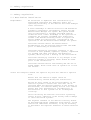
Requirements
We would like to emphasise that installation by an
unqualified technician may adversely affect the
operating reliability of the vehicle and could endanger
other road users.
A basic knowledge of vehicle electrical and mechanical
systems is required to successfully install the VDO
Kienzle Fleet Manager 200 system. The system should
only be installed by a suitably qualified vehicle
technician with a basic knowledge of the operation of
computers. We strongly recommend that technicians
attend a VDO Kienzle training course to acquire the
skills needed for installation, conf iguration and
operation of the VDO Kienzle Fleet Manager 200 system.
Installers should consult the manufacturers’
documentation for the specific vehicle make and model
prior to undertaking an installation.
Installers should pay particular attention to the
location of fuel systems, hydraulic systems, compressed
air systems and other electrical and mechanical
systems, which may have a bearing on the installation.
Installers should pay attention to any changes to the
vehicle’s systems or settings, which should be noted
prior to the installation.
Installers should refrain from smoking and the use of
naked flames, which could caus e an ignition in or near
the vehicle.
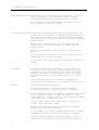
Secure the workplace Remove the ignition key from the vehicle’s ignition
lock.
Ensure that the vehicle’s engine cannot be
unintentionally started during the installation.
Record all data stored in the volatile memor y of the
vehicle’s systems to ensure that such data can be
restored. When the negative terminal of the battery is
disconnected, all volatile memory will be lost. Please
ensure that such information is recorded prior to
disconnection so that systems can be reconfigured
correctly.
Short-circuiting the vehicle’s electrical system may
result in fire, explosion of the battery and/or damage
to other electrical systems.
The negative terminal of the vehicle’s battery should
be disconnected before commencing insta llation. If the
vehicle has additional batteries, it may be necessary
to disconnect the negative terminals of these batteries
too.
3
2. Safety regulations
Note during installation Should it be necessary to remove seats, covers or
other components, care should be taken to avoid
accidental damage and/or disconnection of cables.
All components should be checked for damage prior to
being installed into the vehicle.
Installation position Installers should ensure that the components of the
product do not influence or hamper the fun ctioning of
the vehicle’s systems. Care should be taken to ensure
that the product’s components do not get damaged during
installation.
Ensure that sufficient space is available for all
components of the product prior to commencing the
installation.
Please pay attention to the routing
wiring.
of cables and
Do not install the product in or near the location of
mechanical or electrical airbags.
Do not drill into supporting or stabilising braces or
beams.
Procedure
For small installation opening s, a drill should be
used. For larger openings, a conical milling cutter,
compass saw or file should be used. All rough edges
should be trimmed. Careful attention must be paid to
the manufacturers’ safety regulations for all tools
used.
Oils and fuels must be collected in appropriate
containers and disposed of in accordance with the law.
Wiring
Note the product’s wire gauge.
If the wire gauge is reduced, current density
increases which may cau se the wiring to overheat.
Cables should be routed in existing channels and should
not be routed parallel to ignition cables or other
cables subject to high current. Cables should be fixed
with cable-ties or adhesive tape.
Do not route cables over moving parts. Do not fix
cables on the steering column.
Ensure that the cables are not exposed to pulling,
pressure or shearing deformation.
If the cables are routed through drilled holes, rubber
grommets or similar protection should be provided.
Suitable cable-strippers should be used to strip
insulating material from cables and cable -strippers
4
2. Safety regulations
should be adjusted to avoid damaging or separating the
wire strands.
Cables should only be connected using smooth solder or
suitable crimping lugs.
A proper crimping tool should be used on all crimping
lugs.
Careful attention must be paid to the manufacturers’
safety regulations for all tools used.
Insulate free strands to prevent short -circuits.
Connections to vehicle power supply must be installed
with a fuse or current limiting device.
Be aware that short-circuiting may be caused by faulty
connections and crushed or damaged cables.
Short-circuiting the vehicle’s electrical system may
result in fire, explosion of the battery and/or damage
to other electrical s ystems. To prevent this, all
connections carrying current must be soldered and
insulated correctly. Other connections such as the
speed signal, RPM signal, brake light or clutch switch
can be made with crimping lugs.
Incorrect connections can lead to sho rt circuits.
Connections should only be made in accordance with the
vehicle’s wiring diagram.
Current and voltage should be measured with a
multimeter or diode test lamp. The use of inadequate
test equipment may result in the damage to control
devices or other electrical systems.
2.2 Note after installation
Reconnect the vehicle’s ground cable to the negative
terminal of the battery.
Re-configure the values in the volatile memory of all
systems.
Check all vehicle functions.
Explain the functions of the VDO K ienzle Fleet Manager
200 system to the customer and give the customer the
attached operating manual.
2.3 Note during operation
The product must be operated in accordance with
operating instructions. Failure to use the product as
directed might result in perso nal injury, material
damage and/or damage to the environment.
5
3. Introduction
3. Introduction
3.1 Confirmation of conformity
e1
The product was developed, produced and tested according
to regulations 71/245/EWG, which were updated with
95/54/EG and the recognized state -of-the-art.
021320
3.2 Utilisation as directed
The product is only for the use in earthbound vehicles and working
machines.
3.3 Declaration of conformity
We declare on our own responsibility that the product
is in compliance with following norm(s) or documents:
DIN EN 50081-1 (03/93), DIN EN 50082 -2 (02/96)
6
3. Introduction
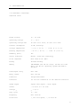
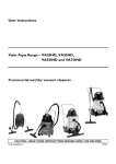
3.4 Product overview
Vehicle Unit
Rated voltage
12 / 24 Volt
Operating voltage
9 ... 36 V
Operating voltage max.
40 Volt for 1 hour, 50 Volt for 5 min.
Current consumption
30 mA (Stand by)
Storage temperature
- 4 ºF (- 20 ºC) ... + 158 ºF (+ 70 ºC)
Working temperature
- 40 ºF (- 40 ºC) ... + 185 ºF (+ 85 ºC)
Humidity (max.)
95%
Serial interface
Master /Slave bus technology
Clock component
Real Time Clock (RTC)
Backup
Lithium Battery
Memory
1MB EEPROM (512 kB for trips, 128 kB for tacho
data, 360 kB for operating system and device
drivers)
Interrupter relay
max. 25A
Relay output
max. 150 mA
Indicator
Integrated buzzer
Interface
I2C for the connection of the vehicle interf ace
Speed signal
Square wave signal / Sine signal
Offset
- 50 Volt to + 50 Volt
Voltage
pp
pp
> 0,5 V
Duty cycle
1% - 99%
Frequency
max. 5000 Hz
Protection
+
/- 600 Volt spike,
+
/- 50 Volt DC
7
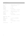
3. Introduction
RPM – signal
Square wave signal / Sine signal
Offset
- 50 Volt to + 50 Volt
Voltage
pp
pp
> 0,5 V
Duty cycle
1% - 99%
Frequency
max. 5000 Hz
Protection
+
3. Frequency input
Square wave signal / Sine signal
Offset
- 50 Volt to + 50 Volt
Duty cycle
1% - 99%
Frequency
max. 10.000 Hz
Protection
+
Digital inputs / Analog
inputs
4
Trigger voltage
0 – 38,33 Volt (programmable)
Resolution
150 mV
Frequency
max. 1 Hz
Protection
+
Protection class
IP 54
8
/- 600 Volt spike,
/- 600 Volt spike,
/- 300 Volt spike,
+
/- 100 Volt DC
+
/- 50 Volt DC
+
/- 50 Volt DC
3. Introduction
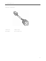
Vehicle Interface
Connection
Compact plug
Attachment
One way push nut
9
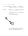
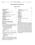
3. Introduction
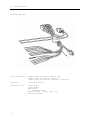
Wiring Harness
Plug connections
Compact plug for FM 200 vehicle unit
Compact plug for vehicle interface
Compact plug for starter interrupt connection
Indicator
Integrated buzzer
Connections for
Power supply
Speed signal
RPM signal
3rd. Frequency input
Digital input / analog input (4)
Switching output
10
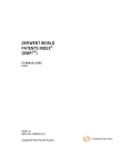
3. Introduction
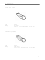
Driver Plug (blue)
Case
Plastic
Memory
8kb EEPROM
Driver ID, Access authorization , Date and Time
Vehicle Plug (green)
Case
Plastic
Memory
256kb EEPROM
Several memory sectors for trips and tacho data
11
3. Introduction
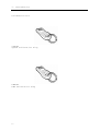
Calibration Kit
SPDCAL
Speed Calibration Plug
RPMCAL
RPM Calibration Plug
12
3. Introduction
3.5 Order numbers
X10.723/002/002
VDO Kienzle Fleet Manager 200 Kit Hardware
X39.723/002/029
Vehicle Unit FM 200
X39.723/002/030
Wiring Harness FM 200
X39.723/002/033
Vehicle plug FM 200 (green, 256 kB)
X39.723/002/006
Driver plug FM 200 (blue, same as FM 100)
X39.723/002/005
Vehicle Interface
X39.723/002/031
Metal housing FM 200
X39.723/002/004
One way screws FM (4x)
X39.723/002/034
PC Software Fleet Manager 2001 CD
X39.723/002/009
PC Download Module
X39.723/002/051
Harness Converter FM100 => FM200
X39.723/002/035
Installation and User Manual Software, German/English
X39.723/002/042
User Manual Hardware, German/English
X39.723/002/043
Free
X39.723/002/028
Calibration Kit (2x calibration plugs, same as FM 100)
13
3. Introduction
3.6 System requirements
The VDO Kienzle Fleet Manager 200 is designed for
utilisation in vehicles, special vehicles and working
machines with a 12/24 electrical system. VDO Kienzle
Fleet Manager 2001 application softwar e is required to
complete the installation process.
3.7 System description
The VDO Kienzle Fleet Mana ger 200 is an on-board
computer for utilisation in earthbound vehicles,
special vehicles and working machines. The system is
designed to record vehicle information as speed, RPM,
temperature data and fuel data, parking, stop and
driving times as well as ot her vehicle status
information. It is possible to configure the system to
record tacho data with a one second interval. This
tacho data can include date, time, speed, RPM as well
as the current status of the digital/analog inputs. To
enforce driver identif ication, the VDO Kienzle Fleet
Manager 200 is equipped with a relay, which can be used
to interrupt the vehicle’s starter circuit. Driver
identification is carried out by means of a driver
specific blue plug. A vehicle specific green plug is
provided for the data extraction. Trip and status data
is analysed and processed using the VDO Kienzle Fleet
Manager 2001 application software. The Microsoft SQL
Server database provides flexibility and simplifies the
processing and exporting of information.
14
4. Installation
4. Installation
4.1 Technical requirements
To install the VDO Kienzle Fleet Manager 200 system,
the workshop needs:
- Standard technical equipment and appropriate tools
for use with vehicles .
- Personal computer with a CD -ROM drive (minimum
Pentium 100 with a minimum of 16 MB RAM and a minimum
of 80 MB of free disk space, CD – ROM drive,
available parallel port ). The personal computer
should be running the Microsoft Windows 95 or Windows
98 operating system.
- VDO Kienzle Fleet Manager calibration set
(calibration kit).
4.2 Personal requirements
The technician who will undertake the installation of
the VDO Kienzle Fleet Manager 200 system:
- Must be a trained vehicle technician.
- Should have a knowledge of how to use a personal
computer.
Attention
Installation should only be undertaken by a vehicle
technician with comprehensive occupation specific
knowledge whom has complete command of the actions
required by the occupation.
We would like to emphasize that installation by an
unqualified technician may adversely affect the
operating reliability of the vehicle and could endanger
other road users.
Please take note of the safety information starting on
page 3 of the section entitled " 2. Safety regulations".
15
4. Installation
4.3 Tools
Standard technical equipment and appropriate tools for
use with vehicles are required to install the VDO
Kienzle Fleet Manager 200 system. Vehicle specific
tools may be required for the removal of consoles and
covers.
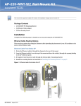
4.4 Installation vehicle unit
Installation position The vehicle unit must be installed inside the
passenger compartment or the driver cabin, to protect
it from possible damage by water or other environmental
factors .
Attention!
Please take note of the sa fety regulations on page 4
concerning the Installation position . The unit should
not be installed in or near the ventilation or heating
systems, which may cause it to overheat.
The unit should be installed in a position where it
will not be subjected to pressure, impact or excessive
vibration.
Select the installation position carefully before
proceeding with the installation.
Mark and drill the required holes.
Route cables from the uni t to the appropriate senders
within the vehicle. Additional information can be
found in the wiring diagram.
After connecting the system components and performing a
system test, mount the vehicle unit securely, making
use of the optional metal armoured hou sing if required.
The armoured housing is available as a spare part. It
can be used as protection against manipulation.
16
4. Installation
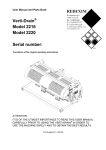
4.5 Installation vehicle interface
Installation position The vehicle interface must be installed inside the
passenger compartment or the driver cabin, to protect
it from possible damage by water or other environmental
factors.
Attention!
Please take note of the safety regulations on page 4
concerning the Installation position . The vehicle
interface should not be installed in or near the
ventilation or heating systems, which may cause it to
overheat.
The vehicle interface should be installed in a position
where it will not be subjected to pressure, impact or
excessive vibration.
Select the installation position carefully before
proceeding with the installation.
Drill size 13/16” - 20 mm
Mark and drill or cut the required hole.
Remove the mounting clip from the vehicle interface.
Remove the protection film from the gumm ed surface of
the protection ring and press it firmly against the
back of the interface. Insert the interface into the
mounting hole and slide the mounting clip into
position.
17
4. Installation
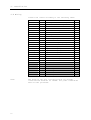
4.6 Wiring
Connect the cables according to the following table:
Colour
Red
Black
Brown
Blue/white
Black/whit
e
Brown/whit
e
Green
Pinno.
12
1
2
19
18
2
20
Connection
Battery PWR (use 7.5 amp in
line
fuse)
Ignition
(use 7.5 amp in line
fuse)
GND
Speed
Speed PWR (For powered sending
units)
Speed GND
RPM signal
Brown/red
22
Switching output
Violet
21
Additional frequency input
White/viol
et
White/red
5
6
3
4
Digital/analog
Digital/analog
Digital/analog
Digital/analog
Black
Black
A1
A2
Starter interruption
Starter interruption
(red)
(brown)
12
7
Buzzer PWR
Buzzer GND
Black
Black
Black
Black
9
8
10
13
Code Plug PWR
Code Plug Data
LED
Code Plug GND
White/gree
n
White/yell
ow
Note:
18
input
input
input
input
no.
no.
no.
no.
Term
30
15
31
1
2
3
4
The wires on the grey coloured groun d are already
connected and need not be linked. All power connections
must be fuse protected.
4. Installation
4.6.1 Interruption
The VDO Kienzle Fleet Manager 200 has an internal relay
intended exclusively for the interruption of the
vehicle’s starter circuit.
Connection
Connect the two starter interruption wires to the
corresponding terminals on the back of the vehicle
unit. Cut the wire from the ignition lock to the
starter (term 50) and solder the starter interruption
wires from the VDO Kienzle Fleet Manager 200 uni t onto
the ends of the wires from the starter circuit. These
wires can be connected either way around because the
relay is a normally closed relay, which is opened upon
driver registration.
Attention!
The internal relay is intended only for starter circui t
interruption (term 50). This relay should not be used
to interrupt the fuel pump or ignition (term +15) power
supplies. For high current starter solenoid
applications an additional relay may be required .
4.6.2 Additional switching output
The VDO Kienzle Fleet Manager 200 has an additional
switching output protected from overloading. To
activate this output, one or more events must be
configured in the Fleet Manager 2001 application
software. The output signal of the Fleet Manager 200 is
ground. The maximum current of a device connected to
this output must not exceed 150 mA.
Connection
Connect the brown/red wire (FM pin 22) to the ground
contact of the relay (Relay pin 85). Connect the
positive contact of the relay (Relay pin 86) to term
key on power or const ant power (depending on the
operation) of the vehicle power supply.
19
4. Installation
4.7 Status inputs
The VDO Kienzle Fleet Manager 200 is equipped with four
status inputs. These inputs are programmable and can be
used to monitor either digital or analog sign als. The
operating range of these inputs is between 0 and 38,88
Volts at a resolution of 150mV. The specific switching
thresholds for the vehicle are stipulated in the Fleet
Manager 2001 software. The system can be configured to
record information when suc h events occur. This
information can be transmitted to the Fleet Manager
2001 software via the green vehicle plug.
Note
This signal must be > 0 volt and can be processed by
the unit in steps of 150mV. As a result, the signal
from certain devices which oper ate on a variable
resistance may not be registered correctly when
connected directly to the Fleet Manager 200 unit.
Please also refer to the technical specifications the
section entitled ” 3.4 Product Overview”.
20
4. Installation
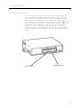
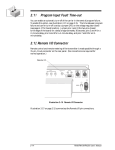
4.8 Serial interface
The serial interface i s currently not supported. It
will be used for additional features such as GSM data
extraction, integration with the Global Positioning
System or the connection of a keyboard. In principle
the interface is based on the Universal Serial Bus like
”Master/Slave” technology, well-known in the computer
industry. This technology allows for more than one
device to be connected to the interface. Appropriate
device drivers for connected devices will be uploaded
via the green vehicle plug to the Fleet Manager 200
unit.
Serial Interface
Wiring Harness
21
5. Configuration
5. Configuration
This section describes the initial configuration of the
Fleet Manager 200 system. For more detailed information
please refer to the Installation and User Manual of the
Fleet Manager 2001 application software or to the
online help function.
5.1 Vehicle plug and Driver plug
Configuration
Take the blue and the green plug out of the Fleet
Manager 200 package. Start the Fleet Manager 2001
application software on your computer.
Note
The FM 2001 software has to be set up for the specif ic
customer. You must configure the events to be monitored
by your Fleet Manager 2001 system before continuing.
Please refer to the online help for more information
about parameters and events.
Insert the green vehicle plug into the download module.
From the “Code Plug” menu, click on "Initialise Plug".
Choose "Vehicle Plug" from the menu. If the vehicle to
be initialised is not shown in the list, click the
"Add" button. Enter an ID number, registration number
and description of the vehicle into the vehicle
properties dialog. Select the appropriate unit type
(here FM 200). Information such as Site and
Configuration Group are not transferred into the unit
and can be configured by the customer at a later stage.
If Configuration Groups have already been define d,
these should be used to configure new vehicles so that
the appropriate default settings are inserted
automatically into the new vehicle records.
Default settings include details on the threshold
values for speed and rpm, and whether the exceeding of
a limit is recorded with or without start and end
odometer.
Click the "Ok" button to save the new vehicle record.
Additional tabs will become available in the vehicle
properties dialog. Use the “Input Configuration”,
“Event Configuration” and “Tacho Configur ation” tabs to
specify which devices are connected to the unit and
which information you would like recorded.
On the “Input configuration” tab, you will notice that
the Speed and RPM inputs are shown as being connected
by default. If there is no RPM signa l connected, please
uncheck this item.
Please ensure that all inputs are calibrated correctly.
For inputs connected to digital devices (switches),
please specify a trigger value in mV. For analog
inputs, please enter any two pairs of values as well as
the corresponding unit of measure. This information
will be used to display information on the tacho data
graph.
22
5. Configuration
Use the “Tacho Configuration” tab to specify which
inputs should be recorded at one-second intervals. It
is recommended that you enable recording of all inputs
after installation. Once the configuration has been
uploaded and a test performed, this setting can be
changed to suit the customer’s requirements.
For more detailed information on these procedures
please refer to the Installation and User Manual of the
Fleet Manager 2001 software or to the online help
function.
All further details of vehicle settings can be entered
subsequently during commissioning at the customer’s
premises.
Then select „Load“ and „Exit“.
Device drivers
The Fleet Manager 200 memory only contains the
operating system at the time of delivery. Before the
on-board computer can be configured with the specific
vehicle data, the current device drivers must be
loaded. This is done with the menu option „Code Plug“ „Initialise plug“ - „Device driver“, or with a
specially programmed „driver plug“, if programming tool
FMDealer.exe is available.
In order to load the device drivers to the green
vehicle plug, it first has to be initialised for the
relevant vehicle.
Open the menu option „Code Plug“ and click on the sub option „Initialise plug“. Select the option „Vehicle
plug“. Follow the instructions on the screen up to step
3 of 4 (Initialise plug with the following data).
Deselect the „Update event configuration“ option and
click on „Continue“. The following screen tells you
that only the vehicle ID is being transmitted to the
plug. Confirm this message.
Open the „Code Plug“ menu option and click on the sub option „Initialise plug“. Select the option „Device
drivers“. Follow the further instructions on the
screen. When you have finished your entries, the device
drivers are loaded to the previously initialised green
vehicle plug.
Insert the vehicle plug into the reader socket in the
vehicle. The device drivers and the vehicle ID are
loaded into the on-board computer. This process lasts
approx. 1 minute.
Caution!
Always wait until the data transfer is concluded before
removing the plug from the reader socket. Correct
transfer is indicated by two short signal tones. If a
different tone sequence is heard, data transfer is
defective and must be repeated. To do this, the vehicle
plug has to be re-initialised and the device drivers
then loaded again. This is necessary, as the
transmission of the vehicle ID and the device drivers
only functions once after re-initialisation.
Note
Using the program FMDealer.exe, it is possible to
format a green vehicle plug in such a way that it can
23
5. Configuration
be used as a permanently functioning „device driver
plug“. It is recommended that this plug be stored
together with the calibration plugs.
Configuration
Open the menu option „Code Plug“ and click on the entry
„Initialise plug“. Select the option „Vehicle plug“.
Follow the further instructions on the screen up to
step 3 of 4 (Initialise plug with the following data ).
Activate the entries „Update event configuration“ and
„Set mileage“. Then you can change the plug format by
moving the relevant control. Confirm the entries by
clicking on the „Continue“ button. The data to be
transferred to the plug are then shown. Con firm this
entry. The data are then transferred to the vehicle
plug.
The configuration data and the odometer reading are
then loaded into the green plug and can be transferred
to the on-board computer. Insert the green vehicle plug
into the reader socket in the vehicle. The data are
then transferred. This process is announced by a short
signal tone at the start and end of the transmission.
The on-board computer is now programmed with the
vehicle ID, the configuration settings and the mileage.
Note
If the vehicle ID is to be changed at a later date, the
green vehicle plug has to be formatted first and then
initialised with the new vehicle ID. The configuration
of the on-board computer remains unchanged.
For configuration of the blue plug and for transfer of
the date and time, proceed as follows:
From the “Code Plug” menu, click on "Initialise Plug".
Choose the second item, "Driver Plug". Insert the blue
driver plug into the download module and click the “Ok”
button. If the required driver is not shown on the li st
click the "Add" button. Enter an ID number and the
driver’s name into the driver properties dialog. Select
the „Vehicle access“ tab and select the appropriate
vehicles. In addition, data on the personnel number and
report group membership can be entered , but these are
not written to the key and can therefore be added
during commissioning at the customer’s premises. On
conclusion of your entries, click on „OK“. The blue key
is now assigned to the previously selected driver and
contains not only the driver ID but also the vehicle
access table.
After installing the VDO Kienzle Fleet Manager 200, the
unit’s real-time clock should be set to the current
date and time.
Note
The software defaults to a time ten minutes ahead of
the current time. You may change th is to any time but
you should allow yourself sufficient time to get to the
vehicle to insert the plug into the vehicle interface.
Caution!
Ensure that the daylight saving is enabled in the VDO
Kienzle Fleet Manager 2001 software!
Software
From the “Code Plug” menu, click on "Set Date / Time”
and then enter the date and time at which you will
24
5. Configuration
insert the plug into the vehicle interface. The driver
plug will be configured with the specified date and
time.
Vehicle
Insert the blue driver plug into the vehicle in terface
at exactly the pre-programmed date and time. The unit
will beep three times indicating the date and time has
been set successfully.
25
5. Configuration
5.2 First initialising
First initialising
Insert the green vehicle plug in to the vehicle
interface. The Fleet Manager 200 reads the data on the
plug and records the vehicle ID, the odometer and
configuration information. The system is now ready for
operation.
Note
Before recording driving information, the system must
be calibrated as described below.
5.3 Distance
Two calibration plugs ("SPD CAL" and "RPM CAL") are
provided for calibrating the VDO Kienzle Fleet Manager
200 system. Before calibrating the system, the blue
driver plug should be initialised as described above.
Calibration (1)
Disarm the system using the blue plug and drive to the
beginning of a demarcated 20 meter distance. Insert the
violet plug labelled "SPD CAL" into the vehicle
interface and drive the demarcated 20 meters. Remove
the violet plug from the vehicle inte rface. The Fleet
Manager 200 unit is now calibrated with the correct
distance to pulse ratio.
Note
The speed calibration plug “SPD CAL” is pre -programmed
for use over 20 meters. This value can be changed
voluntarily.
Calibration (2)
Disarm the system using the blue plug and drive to the
beginning of a demarcated 20 meter distance. Now
measure the exact distance to pulse ratio using the
appropriate measurement tools. It is also possible to
determine the distance to pulse ratio using a roller
test bench. Set the speed calibration plug “SPD CAL” to
the correct distance to pulse ratio using the
“FMDealer.EXE” workshop software. Disarm the system
using the blue driver plug and turn the ignition on.
Insert the calibration plug into the vehicle interface.
The unit will beep three times indicating that it has
been calibrated successfully.
26
5. Configuration
5.4 Number of revolutions
Calibration (1)
Disarm the system using the blue driver plug. Insert
the violet plug labelled "RPM CAL" into the vehicle
interface and start the engine. In crease the engine
speed to 2001 RPM and keep this value constant for a
few seconds. Remove the violet plug from the vehicle
interface. The Fleet Manager 200 will now be calibrated
to the engine speed of the vehicle.
Note
The RPM calibration plug “RPM CAL” is pre-programmed
for use at 2000 RPM. This value can be changed using
the “FMDealer.EXE” workshop software.
Calibration (2)
Disarm the system using the blue driver plug. Now
measure the exact frequency of the RPM signal using the
appropriate measurement t ools. Set the RPM calibration
plug to the correct frequency using the “FMDealer.EXE”
workshop software. Disarm the system using the blue
driver plug and turn the ignition on. Insert the
calibration plug into the vehicle interface of the
vehicle. The unit will beep three times indicating that
it has been calibrated successfully.
Note
For further information on the program FMDealer.exe,
please consult the relevant documentation.
27
6. Function test
6. Function test
6.1 Download data
Test drive
Disarm the system by inserting the blue p lug into the
vehicle interface and wait for the acoustic signal.
Remove the plug and start the engine. Allow the vehicle
to idle in neutral gear for at least two minutes so
that the unit records a sub -trip. Carry out a test
drive.
Read out
After the test drive, turn off the ignition and insert
the green vehicle plug into the vehicle interface. A
beep will be heard indicating the start of data
transmission. At the same time the LED on the vehicle
interface will flash. A second beep will be heard once
data transmission has completed. Remove the green
vehicle plug and insert it into the download module to
transfer the Data to the VDO Kienzle Fleet Manager
2001.
Note
More information on this procedure on this can be found
in the documentation and the online help function of
the VDO Kienzle Fleet Man ager 2001 application
software.
28
7. Starting
7. Starting
7.1 Setting of the vehicle root data
The VDO Kienzle Fleet Manager 200 system allows the
setting of vehicle specific values e.g. threshold
values for speed, RPM, standing times, pa rking times
etc. These values are defined in the VDO Kienzle Fleet
Manager application software and are transferred to the
vehicle using the green vehicle plug.
Software
For information on programming the vehicle root data,
please refer to the documentati on and the online help
functions of the VDO Kienzle Fleet M anager 2001
application software.
After the vehicle root data has been entered, it should
be transferred onto the green vehicle plug.
Vehicle
Insert the green vehicle plug into the vehicle
interface. The data on the plug will be transferred
automatically into the on -board computer. Test drive
the vehicle and download the data into the VDO Kienzle
Fleet Manager 2001 application software to ensure that
the configuration changes were successful.
29
8. Maintenance
8. Maintenance
The VDO Kienzle Fleet Manager 200 unit is maintenance free.
Please ensure that the vehicle interface is kept clean
and free of dust and dirt.
30
9. Troubleshooting
9. Troubleshooting
LED does not flash No voltage
Check the voltage supply of
the Fleet Manager 200.
The Fleet Manager
200 can not be
released
The blue driver plug is not
released for the vehicle
Use the correct driver plug
or get the driver plug
released for the vehicle
The recorded
vehicle data is
incorrect
The Fleet Manager 200 has
not been calibrated
correctly
Calibrate the Fleet Manager
as described again
Time/Date of the
trips are
incorrect
The clock in the Fleet
Manager 200 is misadjust
Set the date and time by
means of the blue driver
plug
The buzzer warns
when turning on
the ignition
The driver registration was
not done or
Register with your blue
driver plug
there is no using
permission for this vehicle
Get your blue driver plug
released for the vehicle
and register with it
31
10. Operating manual for the VDO Kienzle Fleet M anager 200
10. Operating manual for the VDO Kienzle Fleet M anager 200
10.1 Driver registration and disarming of the on -board
computer
For driver registration, insert the blue driver plug
containing your personal ID into the vehicle interface.
The on-board computer issues two beeps and the LED in
the vehicle interface stops flashing. You may now start
the engine. If the LED in the vehicle interface remains
flashing, this indicates that registration has failed
and you do not have permission to drive the vehicle.
Repeat the procedure if you believe you have been
granted permission to drive the vehi cle. Permission to
use the vehicle is defined using the Fleet Manager 2001
application software.
10.2 Data transmission
To transmit data to or from the unit, insert the green
vehicle plug into the vehicle interface.
A short beep indicates the start of data tra nsmission.
The LED in the vehicle interface will flash quickly
during data transmission. A second beep indicates the
start of the second phase of data transmission. A third
beep indicates that data transmission is complete and
the LED will flash at one-second intervals. Only data
recorded since the last download will be transferred.
This is why the time between beeps may be very short.
Should a failure occur during transmission an acoustic
code will sound. Please refer to section " 10.5 Acoustic
signals" for more information.
10.3 Setting of the vehicle root data
The green vehicle plug is used to set the vehicle root
data. This plug should be initialised with the vehicle
threshold values using the Fleet Manager 2001
application software. These values will be transferred
into the on-board computer the next time the plug is
inserted into the vehicle interface.
Details on the various threshold values can be found in
the software manual or the online help function of the
software.
10.4 Setting of date and time
If it is necessary to set the date and time of the
vehicle unit, please refer to the Fleet Manager 2001
software manual.
Insert the blue plug into the vehicle interface at the
exact time pre-programmed with the software. The buzzer
issues three short beeps indicating that the date and
32
10. Operating manual for the VDO Kienzle Fleet Manager 200
time have been set successfully.
10.5 Acoustic signals
The FM 200 on-board computer has a diagnostic function,
which provides information about memory capacity,
communication with plugs and operating conditions. This
information is conveyed by means of the buzzer and the
LED in the vehicle interface.
33
10. Operating manual for the VDO Kienzle Fleet M anager 200
General communication failure
LED:
Buzzer
:
No changes
–––
Armed:
LED:
Buzzer
:
?
off
Requesting driver
registration:
LED:
Buzzer
:
Off
––
––
–– 10 times while
turning on ignition
or until driver registration
Driver registration
correct:
LED:
Buzzer
:
Goes off
–
–
Driver registration
wrong:
LED:
Buzzer
:
?
–
FM200 used memory
capacity
80%-95%:
LED:
Buzzer
:
Off after driver registration
one second after driver registration –
FM200 used memory
capacity
95%-100%:
LED:
Buzzer
:
Off after driver registration
one second after driver registration
––
––
Calibration:
LED:
Buzzer
:
? ? ? ? ? ? flickers
––––––––
–––––––– ... until
removal of calibration plug
Setting date/time with
blue plug:
LED:
Buzzer
:
? flickers during data transmission ?
–
–
–
LED:
Buzzer
:
Off
––––– while exceeding ––––––
Vehicle registration
correct:
LED:
Buzzer
:
? flickers during data transmission ? ? . . .
regular flashing
–
Vehicle registration
wrong:
LED:
Buzzer
:
?
Memory of green plug
full, but
still data to transmit:
LED:
Buzzer
:
Flickers as long as memory available, followed
by
?
?
?
–
–– 5 Seconds tone ––
Communication failure
at data transmission:
During start-up
?
?
?
?
. . . continuous flashing
. . . continuous flashing
–
–
–
––
During calibration
While driving
Exceed threshold value
while driving:
During data transmission
––––––––––––– = 1 second
34
?
–
–
? . . . continuous flashing
––––
10. Operating manual for the VDO Kienzle Fleet Manager 200
35
11. FMDealer Utility
11. FMDealer Utility
The FMDealer Utility replaces the FM100 dealer utility
(Dealer.exe) and contains more enhan ced funcionality.
The utility caters for FM200 plugs as well as for FM100
plugs.
Setup
The FMDealer Utility comes with a Windows setup. For
installation please doubleclick on the setup.exe file
and follow the instructions.
FMDealer.exe runs under:
- Windows 3.1
- Windows 3.11
- Windows 95
- Windows 98
Functionality
Menu FILE
- Exit Shuts down the program.
Menu EDIT
- App Setup
Sets the Date Format (DD/MM/YY or MM/DD/YY).
- Plug Comms
Sets the communications port (LPT1 or LPT2).
Autopolling On/Off (The download module is
automatically polled to see if a plug has been
inserted).
- Language
Sets the language.
Menu CALIBRATION
- RPM/SPEED
Configures the calibration plugs.
Window "CALIBRATION":
Plug Type: Calibration plug for RPM or Speed.
Min: Valid min. value
Max: Valid max. value
Calibration Increment: The Calibration value can be a
multiple of this increment.
Button Increment: Number by which the calibration value
increments or decrements, when the up or down arrow
buttons are pressed.
36
11. FMDealer Utility
Calibration Method:
Manual
Speed: The vehicle is driven the set distance with the
"SPD CAL" plug inserted, then removed.
RPM: The "RPM CAL" plug is inserted, the engine is
revved to the calibration speed and held there. The
plug is then removed. During calibration, the unit beep
in 1 second intervals. The LED will flash as the unit
receives pulses. When the plug is removed, the unit
should beep 3 times to indicate that the calibration is
successful.
Automatic
For known pulses, at the specified engine speed or
distance, { Speed: (pulses/1000m), RPM: (pulses/sec at
1000RPM) } insert plug and wait for 3 beeps.
Diagnostic
The inserted plug is set as a diagnostic plug. The plug
behaves similarly to a manual calibration plug, except
values in the OBC are not chan ged. It is used to verify
whether the unit is detecting pulses, the unit code
plug socket LED will flash at a rate preportional to
the pulse rate.
Menu OPTIONS
- Set Date/Time
Setting Date/Time onto a blue plug.
Note
If required, set Daylight Saving Time!
- Initialise Plugs: Driver (ID)
Vehicle (ID)
Update vehicle unit (Overwrites the vehicle ID in the
FM200 unit if the checkbox is checked)
Odo (green plug)
Clear FM200 memory
Formats a blue plug which can be used to clear the
memory of a FM200 unit
Note
This feature does not work with FM100 units!
- Calibration
Configures calibration plugs.
- Format Plugs
Formats plug memory.
- Calibration (violet)
- Driver (blue)
- Vehicle (green)
- Device Drivers
Format Device Drivers allows one to format a green
FM200 vehicle plug in such way, that the device drivers
can be uploaded more than one time to a FM200 unit.
This allows one to go from vehicle to vehicle without
37
11. FMDealer Utility
re-loading the device driver. No vehicle ID is
transferred during this operation. Caution must b e
taken to label this plug carefully so that vehicles are
not inadvertantly loaded with incorrect device drivers.
Note
38
Take care that the appropriate plug is always chosen.
The "FORMAT" function can also be used to repair
corrupt plugs.
12. Service Information
12. Service Information
This chapter contains service information concerning
the Fleet Manager 200.
39