1
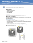
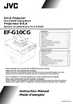
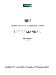
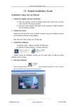
INSTRUCTION MANUAL
FOR ASSEMBLY AND INSTALLATION OF
EF-L1000CG <METAL FIXTURES SUSPENDED FROM CEILING>
LCD Projector Compatible with Installation
Model Name: LX-D1000 (Body’s mass is 4.5 Kg)
For Selling and Installing Stores
■ Read this instruction manual carefully before assembly and/or installation. Be sure to carry out the
work properly always with safety in mind.
■ Do not permit the customers to engaged in assembly and/or installation. Make sure that your customers request you, the professional installers, for assembly and/or installation.
■ It is mandatory that you use the provided accessories for assembly and/or installation work. The metal
fixtures cannot be used for the LCD (liquid crystal display) projectors and appliances other than those
that are designated by our company.
■ The total mass of the metal mixtures for the ceiling is 5.5 Kg.
DETAILS TO BE STRICTLY OBSERVED FOR SAFETY
Before assembly and/or installation, be sure to read carefully the “details to be strictly observed for safety.”
The risk and its extent caused by erroneous handling are demarcated as follows:
WARNING
Probability that can result in critical consequences such as death or serious injury in case of erroneous
handling.
CAUTION
Probability that can result in injury or damage of houses and/or household effects in case of erroneous handling.
WARNING
Carry out installation so that a safety rate definitely comes to
more than 5 times.
Select a strong place where the mass of the LCD projector and
the metal fixtures can be held sufficiently.
If they are installed at a spot having insufficient strength, the
metal fixtures attached to the ceiling can come off and fall, resulting in injury.
Be sure to carry out installation under a ceiling with a horizontal
surface.
Avoid installation under an inclined or warped ceiling.
CAUTION
Take necessary measures to prevent any possible swing using
wires, etc.
Otherwise, temblors and vibrations can result in falls, causing
injury.
Pay attention not to allow any children hang onto the fixtures.
Otherwise, injury can result.
Be sure to install them at a place where there is no other apparatus such as a fire alarm, etc., or malfunction of appliances and
instruments, etc., can result.
BHU30002-036-001
–1–
CHECK AND MAKE SURE
CAUTION: When installing component parts, caution must be
exercised not to use any parts except the ones packed with the body.
Check and confirm before assembly and/or installation that the following parts are packed along with the body as accessories:
No.
Quantity
No.
q
Coupling plate
Names of parts
1
!1
Hexagon head bolts [C] (M10 × 65)
1
w
Supporter for LCD projector
1
!2
Nut
1
e
Assembling bolts (M8 × 25)
4
!3
Washers (for M10)
2
r
Rotary setscrews [E] (M5 × 10)
2
!4
Screws [B] (M8 × 14)
2
t
Screws [A] (M4 × 12)
2
!5
Hexagon wrench (for M5)
1
y
Ceiling plate
1
!6
Hexagon wrench (for M8)
1
u
Inner pole
1
!7
Rotary mini setscrews (M5 × 5)
2
i
Inner pole fixing plate
1
!8
Hexagon socket bolts (M5 × 16)
4
o
Hexagon socket bolts (M5 × 10)
4
!9
Washers (for M5)
4
!0
Collar
1
@0
Nuts (for M5)
4
Names of parts
Quantity
PROCEDURES FOR ASSEMBLY AND INSTALLATION (Refer to Fig. 3)
1.
2.
To begin with, determine the projection range, then the fixing position of the metal fixtures’ ceiling plate. (The projection lens center of
the ceiling plate is apart about 24 mm from that of the LCD projector.
Refer to Fig. 4)
Fig. 1
(Bottom view of LCD projector)
Install the ceiling plate underneath the ceiling as illustrated in Fig. 3.
For the size of the metal fixtures’ fixing hole, refer to Fig. 3-1. Use
the fixing screw of the ceiling plate larger than M8.
WARNING: Check and make certain that there is a safety rate of
more than 5 for the total mass of the metal fixtures including the
LCD projector.
3.
Turn the LCD projector over, and loosen only the angle adjuster located at the position illustrated in the figure. See Fig. 1. (At this
time, take the sponge out from between the angle adjuster and the
body.)
4.
Set the body’s plate to the LCD projector, and slide it in the direction
indicated by the arrow mark. See Fig. 2.
5.
Insert the 2 screws [A] into the two holes provided at the bottom of
the LCD projector, and tighten the angle adjuster. (See Fig. 2 and
Fig. 3)
6.
Set the supporter for the LCD projector from the bottom, tighten the
screws [B], and secure the supporter.
7.
Set the inner pole fixing plate and the inner pole temporarily with 4
hexagon socket bolts (M5 × 10) as illustrated in Fig. 3, and insert the
inner pole into the hole of the coupling plate.
8.
Fix the inner pole fixing plate and the coupling plate with 4 hexagon
socket bolts (M5 × 16), and tighten them with 4 nuts (for M4).
Loosen this portion of
the angle adjuster
counterclockwise.
Fig. 2
t Screws [A] (M4 × 12)
Body’s plate
9.
Adjust the holes of the inner pole and the ceiling plate, put on the
collar, washer, and nut in the order as shown in Fig. 3, and fasten
them with a hexagon bolt [C].
10. Make adjustments on the rotating direction of the entire body of the
metal fixtures, and then tighten the 4 hexagon socket bolts (M5 ×
10) that were temporarily fixed as mentioned in Procedure 7 above.
11. Tighten the inner pole using 2 rotary setscrews [E], and furthermore
secure the inner pole using 2 rotary mini screws.
–2–
Angle adjuster
Slide
(*) Fastening bolt to
install arm (1 bolt)
WARNING
(*) Part
: The asterisked fastening bolt to install an arm (1 bolt)
is built in to constitute a part of the body’s plate.
: Never remove the above-mentioned bolt under any
circumstances since it is absolutely required to
ensure safety.
Fig. 3 ASSEMBLY
t 2 screws [A]
(M4 × 12)
u Inner pole
!8 4 hexagon socket
bolts (M5 × 16)
q Coupling
plate
!7 2 rotary mini
setscrews (M5 × 5)
Fig. 3-1
!1 Hexagon head bolts
[C] (M10 × 65)
20
10
15
5
!2 Nut
150
!3 Washers (for M10)
(109.6)
y Ceiling plate
!3 Washer (for M10)
!0 Collar
(109.6)
i Inner pole
fixing plate
150
Size of fixing hole of base metal fixtures
@0 4 nuts (for M5)
r 2 rotary setscrews [E] (M5 × 10)
!9 4 washers
(for M5)
e 4 assembling bolts (M8 × 25)
o 4 hexagon socket
bolts (M5 × 10)
!5 Hexagon wrench
(accessory)
Body’s plate
(*) Fastening bolts for
body’s plate (4 bolts)
(*) Holder plates (2 plates)
Air inlet (❈)
LCD projector
(*) Fastening bolts for
holder plate (8 bolts)
Hexagon socket bolts
for M5
!4 2 screws [B] (M8 × 14)
Note:
❈ Air inlet:
This is an inlet to bring cool air into the LCD
projector. Do not cover it with a lid, etc.
w Supporter for LCD projector
Unit of indicated dimensions (mm)
WARNING
(*) Parts
: The asterisked parts such as the holder plates (2 plates), fastening bolts for holder plates (8 bolts), and fastening bolts for body’s
plate (4 bolts) are built in to constitute component parts of the body’s plate.
: Never remove the above-mentioned component parts under any circumstances since they are absolutely required to ensure safety.
Fig. 4 FRONT VIEW
Exhaust hole (❈)
24
Unit of indicated dimension (mm)
Note:
❈ Exhaust hole:
This is a hole to exhaust hot air inside the LCD projector. When
installing the unit near a wall, etc., keep it away more than 50 cm
or so from the face of the exhaust hole.
–3–
ADJUSTMENT OF PROJECTION POSITION
1.
(Refer to Fig. 5)
Carry out horizontal and vertical adjustments as follows:
(1) To adjust the horizontal position of the screen, loosen rotary setscrews [E] (there are two pieces on both sides) and 4 hexagon
socket bolts (M5 × 10), and rotate the projector horizontally.
(2) To adjust the vertical position of the screen, loosen the assembling bolts (there are 4 pieces on both sides), then tilt the front of the
projector vertically.
2.
Tighten the rotary setscrews [E], hexagon socket bolts (M5 × 10), assembling bolts, and fix the LCD projector.
Fig. 5 ADJUSTMENT
Hexagon wrench
(accessory)
126.2
Rotary setscrew [E]
Assembling bolt for M8
148
405
Tip of LCD Projector ~ Center of ceiling plate
48
Lens center
Tilt adjusting latitude
of 15 degrees
453
Assembling bolt
(M8 × 25)
339
367
Unit of indicated dimensions (mm)
FILTER CLEANING
(Carry out filter cleaning with appropriate intervals)
Before replacing the filter, never forget to turn
OFF the main power switch and unplug the
power cord from the outlet.
1.
Fig. 6 REPLACEMENT
Remove the 2 filter guard fixing screws,
and remove the filter guard.
2.
Push the knob of the filter cover in the
direction indicated by the arrow mark, and
raise it.
3.
Take out the filter, wash it well in water or
synthetic detergent, and dry it completely.
4.
Set the filter on the filter cover, and install
the filter cover on the body.
5.
Tighten 2 filter guard fixing screws, then
set the filter guard.
Filter guard
Filter
Filter cover
2 filter guard
fixing screws
VICTOR COMPANY OF JAPAN, LIMITED
–4–
Printed in Japan
0999YMPS/VP