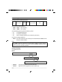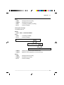
1
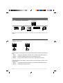
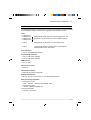
UNI-TELWAY
Section
Contents
Page
1 General
5
1.1
Network documentation presentation
5
1.2
Communication principles
1.2-1 General
1.2-2 Managing the UNI-TELWAY link
6
6
8
2 Operating principle
9
2.1
Sending a message
2.1-1 Access to the bus
2.1-2 Master to slave
2.1-3 Slave to master
2.1-4 Slave to slave
9
9
10
11
12
2.2
Connecting a station
13
2.3
Multiple exchange operation
14
3.1
General
15
3 Communication architecture
15
3.2
Examples of architectures
3.2-1 UNI-TELWAY in RS 485 mode
3.2-2 UNI-TELWAY in RS 232 mode
16
16
16
3.3
Devices which can be connected
17
___________________________________________________________________________
1
E
UNI-TELWAY
Section
Contents
Page
4 Characteristics and performance
19
4.1
Summary of UNI-TELWAY services
19
4.2
UNI-TELWAY on an isolated RS 485 link
4.2-1 Physical characteristics
4.2-2 Performance
20
20
21
5 Hardware installation
23
5.1
General
23
5.2
Wiring system
24
5.3
Description of the equipment
5.3-1 Trunk cable
5.3-2 TSX SCA 50 T-junction box
5.3-3 TSX SCA 62 subscriber socket
5.3-4 Terminal port isolation box : TSX P ACC01
26
26
26
26
27
5.4
Connecting devices
5.4-1 Principle of daisy chain connection
5.4-2 Principle of tap link connection
28
28
28
5.5
Installing the line
5.5-1 Installation
5.5-2 Connecting the shielding
5.5-3 Line termination
29
29
29
29
5.6
Installing the TSX SCA 50
5.6-1 Mounting
5.6-2 Wiring
5.6-3 Line termination
30
30
30
30
E
___________________________________________________________________________
2
UNI-TELWAY
Section
Contents
Page
5.7
Installing the TSX SCA 62
5.7-1 Mounting
5.7-2 Addressing
5.7-3 Wiring
5.7-4 Line termination
31
31
31
32
32
5.8
Installing the TSX P ACC 01
5.8-1 Mounting
5.8-2 Internal view
5.8-3 Wiring
5.8-4 Configuring the operating mode
5.8-5 Line termination
33
33
33
34
34
34
6 Appendix
35
6.1
Coding the address on TSX SCA 60 / 61 / 62 units
35
6.2
Coding frames
36
E
___________________________________________________________________________
3
Section
General 11
1 General
1.1
Network documentation presentation
This manual is designed for users implementing a UNI-TELWAY network.
The complete network documentation set is structured in the following way :
• general information on X-WAY communication is covered in the Communication
Reference Manual, TSX DR NET,
• general information on hardware is described in the in the User's manual :
TSX DM 37E,
• general information on the installation of the software for the various networks is
given in the manual : TLX DM PL7 M10E,
• information specific to each network is given in the specialized manuals :
- FIPWAY network
: TSX DG FPWE
- UNI-TELWAY bus
: TSX DG UTWE (this document)
- Modbus/Jbus protocol
: TSX DG MDBE
- PCMCIA cards
: TSX DM37E, part K
Note :
Each module is supplied with operating instructions for installing hardware in the PLC.
General
AEG
TSX DR NET
FIPWAY
UNI-TELWAY
AEG
AEG
TSX DG FPW
TSX DG UTW
AEG
TSX DM 37N
Modbus/Jbus
AEG
TSX DG MDB
AEG
TLX DM PL7M
HARDWARE SOFTWARE
___________________________________________________________________________
5
1.2
Communication principles
1.2-1 General
UNI-TELWAY is a standard for communication between control system components
(PLCs, MMI terminals, variable speed drives, numerical controllers, weighing equipment,
etc).
UNI-TELWAY provides easy communication with devices such as supervision and
management computers.
Examples of applications :
• management of control and
monitoring equipment by a PLC,
• man-machine interface and
supervision function.
TSX 37
TSX 37
ATV Variable speed drive
NUM Numerical controller
CCX 77
TSX 47
XGS Inductel
XGS
On
OK
L1
L2
DEF1
DEF2
IN1
IN2
OUT1
OUT2
___________________________________________________________________________
6
General
1
UNI-TELWAY requires :
• a master station which supervises the datalink and controls its operation. It manages
the communication rights of the various connected stations. This station is a PLC of
type :
- TSX 47 to 107 equipped with a UNI-TELWAY module (integrated in the processor,
or TSX SCM 21.6 communication module),
- TSX 17 equipped with a UNI-TELWAY module (TSX SCG 116),
- TSX 37 equipped with a TSX SCP 114 PCMCIA card (TSX SCP 111 for specific
applications) or communicating via the terminal port.
• 1 to 27 slave stations which process the various data transported via the network.
It should be noted that a station can have several datalink addresses (logical
addresses defined by the hardware or the software depending on the type of
device). For example, PLCs can use up to 3 datalink addresses, while CCX 17
operator panels use
2, etc.
A master station always has datalink address 0. There can be up to 27 slave devices
which share 98 datalink addresses.
It is advisable to use consecutive datalink addresses for performance reasons.
___________________________________________________________________________
7
1.2-2 Managing the UNI-TELWAY link
UNI-TELWAY is used for communication at equal levels and sends messages from :
1
Master to slave.
2
Slave to master.
3
Slave to slave.
TSX 37
Master
Bus manager
1
Slave 1
2
3
Slave 2
Slave 3
Slave n
Slave to slave communication is performed in two steps which are automatically linked
together without any action being necessary from either the processor or the application
program of the master station PLC :
• routing of the message to the master module (slave n° 2 to the UNI-TELWAY module
of the master),
• automatic direction of this message to the destination station (slave n° 3).
The UNI-TELWAY bus and its UNI-TE application protocol coordinate activity between
intelligent devices and enable :
• communication from one application to another, for example between PLCs,
• communication from an application to the system of a device (for example : reading
bits, words, managing operating modes, etc).
___________________________________________________________________________
8
Section 22
Operating principle
2 Operating principle
2.1
Sending a message
2.1-1 Access to the bus
The master cyclically interrogates each station. It knows, from the configuration, the
number of datalink addresses to scan.
The master scans each datalink address in ascending order (Polling).
If there is no response at the end of a time period TO (Time Out), the request is repeated.
If there is no response a second time, the slave is provisionally removed from the polling
list.
The value of the Time Out can be configured in the master.
___________________________________________________________________________
9
2.1-2 Master to slave
The datalink master can send its message at any time during the "polling" cycle.
This message can carry a request, or a UNI-TE response or unsolicited data.
The response from the slave can be :
• information indicating that the message has been received (ACK),
• information indicating that the message has been received but that due to insufficient
resources, it will not be processed (NACK).
No response at the end of the time period TO (Time Out) indicates that the message was
incorrect or that the slave was not present.
TSX 37 Master
Datalink
address 1
Datalink
address i
Datalink
address n
Polling
EOT
Polling datalink address i
EOT
Message 1
ACK
Polling n
EOT
Polling
EOT
Etc.
___________________________________________________________________________
1 0
Operating principle
2
2.1-3 Slave to master
The slave can only send its message when it is polled by the master. This message can
be a request, a confirmation or unsolicited data.
The response from the master can be one of the following :
• information indicating that the message has been received (ACK),
• information indicating that the message has been received but that due to insufficient
resources, it will not be processed (NACK).
No response at the end of the time period TO (Time Out) indicates that the message was
incorrect.
TSX 37 Master
Datalink
address 1
Datalink
address i
Datalink
address n
Polling 1
EOT
Polling i
Message
ACK
Polling n
EOT
Polling 1
EOT
___________________________________________________________________________
1 1
2.1-4 Slave to slave
Communication between slaves is performed in two steps which are automatically
linked together by the datalink master :
• sending slave to master,
• master to destination slave.
TSX 37 Master
Datalink
address 1
Datalink
address i
Datalink
address i + 1
Datalink
address n
Polling 1
EOT
Polling i
Message for station n
ACK
Message from station i
ACK
Polling i + 1
EOT
___________________________________________________________________________
1 2
Operating principle
2.2
2
Connecting a station
Summary
The master polls the datalink addresses from 1 to "n" :
• "n" is the number of datalink addresses indicated when the master is configured (the
configuration procedure is described in the documentation for the device performing
the master function),
• n = 31 in the default configuration.
Connecting a station
If the station address is higher than n (maximum number of slaves polled), the master
will need to be configured again to include the new address.
If the new station was included in the configuration of the master, the connection is
performed automatically.
Disconnecting a station
When a station does not respond to the master's polling (power break, physical
disconnection, etc) it is declared as missing. The master re-interrogates a missing
station periodically (every tenth cycle) to enable it to be reconnected.
If the master station is no longer operating, the activity on the medium disappears. The
polling system is only reactivated when the master resumes operation.
In all cases, a red indicator lamp indicates that a station is no longer being polled (for
example, ERR lamp on PLCs).
This indicator lamp is generally located on the communication module of the station
concerned.
___________________________________________________________________________
1 3
2.3
Multiple exchange operation
UNI-TELWAY can be used for multiple exchange operation. A station can initiate an
exchange on the bus while other stations are waiting for responses to previous
exchanges.
Example
Sending a message from the datalink master to :
• slave i,
• slave j.
Sending back data after producing the responses.
Polling i
Rqi
Rqj
Polling j
CRi
CRj
Datalink
Preparation
of request i
Preparation
of request j
Processing of
CRi
Processing of
CRj
Master
Production
of confirmation
Slave i
Awaiting
polling i
Production
of confirmation
Slave j
Awaiting
polling j
___________________________________________________________________________
1 4
Section 33
Communication architecture
3 Communication architecture
3.1
General
UNI-TELWAY integrates into a communication architecture which conforms to the OSI
model.
7
APPLICATION
UNI-TE
6
PRESENTATION
5
SESSION
4
TRANSPORT
3
NETWORK
X-WAY
Addressing system
2
DATALINK
UNI-TELWAY
1
PHYSICAL
RS 485
UNI-TE application layer
This is a list of requests common to all devices (standard requests) or specific to certain
products (specific requests for PLCs or numerical controllers).
It provides the following services :
• reading/writing of objects (bits, words, etc),
• management of operating modes (Init, Run, Stop),
• bus and device diagnostics,
• uploading and downloading of files and programs,
• semaphore management.
Network layer
This provides the functions for routing messages from the sender to the destination.
Each communicating device is identified by a unique address.
UNI-TELWAY datalink layer
This manages the access rights to the line for the various devices, according to a Master/
Slave procedure. A slave device is identified by its datalink address(es). The fixed
master allocates the bus successively to the datalink addresses.
Physical layer
It is an industrial bus with an isolated RS 485 physical interface. For certain specific
applications the physical layer can be 20 mA CL or RS 232 with no modification of the
higher layers.
Application example : data exchange by Modem via an RS 232 link.
___________________________________________________________________________
1 5
3.2
Examples of architectures
3.2-1 UNI-TELWAY in RS 485 mode
TSX 37 Master
CCX 17
TSX 17-20
TSX 37
TSX 37
ATV 16
RS485 is the most frequently used configuration. The master communicates with all the slaves on the
network.
3.2-2 UNI-TELWAY in RS 232 mode
Example : Modem link
TSX 37
Modem
TSX 37
Modem
A UNI-TELWAY RS 232 station is connected to the telephone network in the following
way :
• step 1
: change the UNI-TELWAY RS 232 card to CHARACTER MODE protocol,
• step 2
: initialize the Modem and connect to the telephone line,
• step 3
: return the UNI-TELWAY RS 232 card to UNI-TELWAY protocol.
A UNI-TELWAY RS 232 station is disconnected from the telephone network in the
following way :
• step 1
: change the UNI-TELWAY RS 232 card to CHARACTER MODE protocol,
• step 2
: disconnect the telephone line.
___________________________________________________________________________
1 6
Communication architecture
3.3
3
Devices which can be connected
The following list of devices which can be connected is not exhaustive. It may be updated
with the addition of further devices which support the UNI-TELWAY protocol.
PLCs :
•
•
•
•
TSX/PMX 47
TSX/PMX 67
TSX/PMX 87
TSX/PMX 107
equipped with a UNI-TELWAY module (integrated in the
processor or a TSX SCM 21.6 communication module)
• TSX 37
equipped with a TSX SCP 111/114 PCMCIA card
• TSX 17
equipped with specific modules (refer to the hardware
documentation for this micro-PLC)
Cell controllers :
• CCX 77 with MONITOR software.
Programming terminals :
• FTX 417 with XTEL software,
• FTX 507 with XTEL software.
MMI terminal :
• CCX 17, XBT
Numerical controller :
• NUM xxx
Identification system :
• XGS inductive sensors (Inductel)
Variable speed drives :
• ATV 16, ATV 45, ATV 66, RTV 74, RTV 84, MASAP MSP-62.
Data processing equipment :
• Connection to level 2
- BULL , DIGITAL , HEWLETT-PACKARD , IBM.
• Connection to level 1
- SCIAKY, ARROW, KISTER, etc.
Local area networks :
• FACTOR , LAC/LAC2
___________________________________________________________________________
1 7
Section 44
Characteristics and performance
4 Characteristics and performance
4.1
Summary of UNI-TELWAY services
Whichever physical interface is used, the services which can be used on UNI-TELWAY
(Application layer), are those provided by UNI-TE, that is :
• requests with confirmation in point-to-point mode (maximum length of a frame :
240 bytes on TSX 37 and 128 bytes on other products),
• unsolicited data without confirmation in point-to-point mode (maximum length :
240 bytes),
• broadcast messages (maximum length : 240 bytes).
Note :
A detailed list of UNI-TE services and their coding is provided in the X-WAY Communication
Reference Manual, TSX DR NET. This list is also provided as an appendix to this document.
Additional service which can be used : exchange of event-triggered data. This is the
exchange of unsolicited data between slaves and the master (maximum 8 bytes).
___________________________________________________________________________
1 9
4.2
UNI-TELWAY on an isolated RS 485 link
4.2-1 Physical characteristics
Transmission and configuration
Transmission mode
Asynchronous in baseband
Data rate
From 1 200 bits/s to 19 200 bits/s
Medium
Shielded double twisted pair
Number of devices * (without repeater)
28 devices maximum
Datalink addresses
98 datalink addresses
Bus length
1 000 metres maximum excluding tap links
Tap links
20 metres maximum
* Reminder
27 slaves + 1 master
(It should be noted that this is the maximum number of datalink addresses, which may represent
fewer devices).
___________________________________________________________________________
2 0
Characteristics and performance
4
4.2-2 Performance
The application to application response time on the UNI-TELWAY bus is linked to :
• the network cycle time (NCT),
• the software response time of the client and server devices. Each device has its own
software response time, which cannot be quantified here (see note on the next page),
• the degree of asynchronism between the client-network-server cycles.
The network cycle time is the time separating two consecutive interrogations of the same
datalink address.
This time depends on :
• the number of datalink addresses polled,
• the data rate,
• the station turnaround time (time between one "polling" and its acknowledgment),
• the number, length and type of messages (master to slave, slave to master or slave
to slave dialog).
The diagram to the right
shows the Network Cycle
Time (NCT), excluding
messages, for data rates of
9600 and 19200 bits per
second :
NCT (no messages)
(mS)
A : 9600 bps
400
B :19200 bps
300
200
100
1
4
8
12
16
20
24
27
Addresses
(Slave)
Turnaround time = 5 ms.
When there are messages, the network cycle time is determined by adding the following
values (in milliseconds) to the above curves :
Direction of exchange
9 600 bps
19 200 bps
M
→
S
24
+
1.2 N
17
+
0.6 N
S
→
M
19
+
1.2 N
12
+
0.6 N
S
→
S
44
+
2.3 N
29
+
1.15 N
(N = Number of usable characters corresponding to the message to be exchanged).
___________________________________________________________________________
2 1
Note :
The application to application response time in a distributed control system architecture not only
depends on the communication system, it also depends on :
• the processing time of the devices sending and receiving the message,
• the degree of asynchronism between the cycles of the bus and the processors.
This response time must
be evaluated by the
designer of each application
according to the devices
which are connected.
Event
Device 1
Confirmation
CT1 CT1
UNI-TELWAY bus
The processing time for a
device can vary from one to
two cycle times depending
on the degrees of
asynchronism.
Device 2
CT1 CT1
NCT
NCT
CT2 CT2
Action
NCT = Network Cycle Time (UNI-TELWAY bus).
CT1 = Device 1 bus Cycle Time.
CT2 = Device 2 bus Cycle Time.
___________________________________________________________________________
2 2
Section 55
Hardware installation
5 Hardware installation
5.1
General
The methods used for connection to the UNI-TELWAY bus are specific to each device
which is connected (see the list of these devices in section 3.3). On the device side, the
connection depends on the type of device connected (PLC, variable speed drive,
etc). For more detailed information on these connections (connection equipment,
pinouts, wiring, etc), refer to the specific documentation for each device.
On the network side, devices are connected using one of two methods :
• daisy-chaining, directly with no tap-off at device level (for example : station B),
• by T-shaped tap links (for example : station C), which is an easy method for installing
intermediate stations.
1000 m
20 m
Station
a
Station
b
Station
c
Station
d
___________________________________________________________________________
2 3
5.2
Wiring system
This section, illustrated by the diagram below, covers briefly the methods of connection to
the UNI-TELWAY bus. Connection of the various devices depends on the type of device
itself and is consequently described in more detail the appropriate documentation.
2
1
2
7
2
TER AUX
Adaptor
8
9
4
TSX 37
Device
TSX 37
6
+ Terminal port
+ TSX SCP 114
PCMCIA card
3
Model 40
Model 40
ATV
5
___________________________________________________________________________
2 4
Hardware installation
5
1
TSX CSA••• bus cable, double shielded twisted pair. The shielding must be
connected to the earth of each device.
2
TSX SCA 50 passive T-junction box matches the impedance when it is installed
at the end of the line.
3
TSX SCA 62 passive 2-channel UNI-TELWAY subscriber socket is used for
coding the addresses of both connected devices, and matching the impedance
when it is installed at the end of the line.
4
TSX SCA 61 passive terminal block, used for connecting equipment, with the
appropriate connections (ATV-45 Masap variable speed drives), located at the
extremities of the network . It is used for coding the address of the connected device.
5
TSX LES 64/74 UNI-TELWAY connection boxes, used to connect PLC processors
which have an integrated UNI-TELWAY port as standard (TSX model 40). They are
connected to the bus via tap links (used with a TSX SCA 50). They are used for
coding the addresses of the connected devices.
6
TSX SCP 114 PCMCIA card for connecting TSX 37/57 PLCs to the UNI-TELWAY
bus.
7
TSX P ACC 01 connection box for connecting a TSX 37/57 PLC to the UNI-TELWAY
bus via the PLC terminal port. The connection cable is integrated in the box.
8
TSX SCP CU 4030 UNI-TELWAY connection cable between the TSX SCP 114
PCMCIA card and the TSX SCA 50 T-junction box.
9
TSX P CU 1030 connection cable between the TSX P ACC01 and a PC or FTX 507
programming terminal.
Note :
Items 4, 5, 6, 8 and 9 are specific to the devices which they are connecting. These modules, cables
and special connectors are described in detail in their respective technical documentation
(however the list is not exhaustive).
In the remainder of this section on wiring only those items which are common to the UNI-TELWAY
bus are described, that is :
• the TSX SCA ••• trunk cable,
• TSX SCA 50 T-junction box,
• TSX SCA 62 subscriber socket,
• TSX P ACC 01 connection box.
___________________________________________________________________________
2 5
5.3
Description of the equipment
5.3-1 Trunk cable
This is a shielded cable which is made up of a double pair of twisted conductors. It is
packaged in three different lengths :
• TSX CSA 100 : 100 meters,
• TSX CSA 200 : 200 meters,
• TSX CSA 500 : 500 meters.
5.3-2 TSX SCA 50 T-junction box
This is a passive T-junction box comprising a printed circuit with three sets of screw
terminals. It is used to connect a station via a T-shaped tap link on the trunk cable of a
UNI-TELWAY transmission line. It can be installed, without the need for any special
measures, in any location on the site (wiring ducts, etc).
This T-junction box provides :
• continuity of the electrical signals in all
three directions, as well as shielding
continuity,
• line termination when it is fitted at the
end of the line.
5.3-3 TSX SCA 62 subscriber socket
This is a passive connector comprising a printed circuit fitted with screw terminal blocks
and 15-pin female connectors, for connection to the UNI-TELWAY bus of two devices
which will not take TSX SCA 60/61 connection blocks.
This socket includes :
• address coding of the two devices,
• line termination when it is fitted at the
end of the line.
As this socket is used for address coding,
the connection cable between the socket
and the device is limited to 1.50 m.
___________________________________________________________________________
2 6
Hardware installation
5
5.3-4 Terminal port isolation box : TSX P ACC01
This box is a wiring accessory which connects to the terminal port of TSX 37/57 PLCs
via an integral cable which has a mini-DIN connector at one end. Its connection is
described in the document : Integrated communication, part E.
Note
A TSX SCA 72 active RS 232/RS 485 adaptor box is also available for
connecting a device which has the UNI-TELWAY layers but an RS 232
physical interface (for example, a computer port) to the UNI-TELWAY bus.
___________________________________________________________________________
2 7
5.4
Connecting devices
5.4-1 Principle of daisy chain connection
Here, the subscriber socket (or terminal
block) is directly connected to the trunk
cable of the UNI-TELWAY bus.
Model 40
UNI-TELWAY
5.4-2 Principle of tap link connection
Here, the tap link is the same type of cable
as the UNI-TELWAY bus trunk cable, and
must not exceed 20 meters in length.
SCA 50
SCA 50
The continuity of the signals and the
shielding is assured by the T-junction box.
The connection equipment (cable,
communication module, connector) is specific
to each device which is connected.
___________________________________________________________________________
2 8
Hardware installation
5.5
5
Installing the line
5.5-1 Installation
No particular precautions need to be taken when installing the cable within one building.
It should not be installed on the outside of a building.
However it is important to avoid running power cables close to one another over long
distances.
The line is made up of a bus cable (maximum 1,000 meters from end to end, excluding
tap links) and tap links (maximum 20 meters each).
Note :
See Part C of the TSX DR NET manual (X-WAY communication).
5.5-2 Connecting the shielding
The shielding wire must be grounded via the terminal block and the ground of each
device.
When connecting devices which are some distance away, in order to observe the safety
standards (protection of personnel), it is necessary to check the voltage between the
different ground terminals. There may be a significant difference in voltage between the
ground terminals, which may present a risk to personnel during connection.
If this is the case, the quality of the grounding must be improved.
Note :
See Part C of the TSX DR NET manual (X-WAY communication).
5.5-3 Line termination
Line termination is essential for both ends of the UNI-TELWAY bus. A jumper in the TSX
SCA 50 T-junction boxes and the TSX SCA 62 subscriber sockets, or a TSX SCA 61
terminal block, enables the impedance matching line terminator to close the line.
___________________________________________________________________________
2 9
5.6
Installing the TSX SCA 50
5.6-1 Mounting
65
=
This can be installed on a perforated plate, ref. AM1 PA..., or on an AM1 DE/DP DIN
omega rail with LA9 D09976 fixing plate.
=
AM1-PA••
2 x Ø 5,5
AM1 DE/DP
=
50
=
____________________________________________________________________
5.6-2 Wiring
Place the cable glands contained in the
T-junction box in position and connect the
bus according to the diagram to the right.
Shielding
Insulating sleeve
(compulsory)
1
White
Red
TSX CSA 100/200/500 cable
White
Blue
2
0 VL
3
0 VL
4
D(A)
5
D(B)
1 2 3 4 5
Set the jumper to the ON position, as shown to the right
(the products are supplied in the OFF position).
1 2 3 4 5
When TSX SCA 50 T-junction boxes are connected
directly to a device at the end of the line, this line must be
closed using the line termination circuit.
1 2 3 4 5
5.6-3 Line termination
ON
OFF
___________________________________________________________________________
3 0
Hardware installation
5.7
5
Installing the TSX SCA 62
5.7-1 Mounting
=
The subscriber socket can be installed on :
• a perforated plate, ref. AM1-PA...,
48
65
• an omega rail, ref. AM1 DE/DP with fixing plate
LA9 D09976.
=
35
2 x Ø 5,5
=
50
=
5.7-2 Addressing
The address of a device on the
UNI-TELWAY link is coded using the
micro-switches located on the printed
circuit. Coding is performed by setting the
micro-switches to the OFF position.
Each switch in the addressing system is
assigned a binary weight, 1-2-4-8-16. A
pin which is set to the OFF position
corresponds to binary value 1 (0 at the ON
position).
This address is assigned a parity switch
which must be set so that there is always
an odd number of pins in the OFF position.
See the examples opposite, showing the
coding of stations 5, 11 and the link master
(address 0), or Appendix 6.1 which lists
the codes for all datalink addresses from 0
to 31.
channel 1
ON
OFF
1 2 3 4 5
1 2 3 4 5
SW2
SW1
ON
OFF
channel 2
Address
Parity
ON
1 2 3 4 5 6
OFF
Binary weight
P 16 8 4 2 1
Master station
ON
1 2 3 4 5 6
OFF
P 16 8 4 2 1
Station 5
Station 11
ON
1 2 3 4 5 6
ON
1 2 3 4 5 6
OFF
P 16 8 4 2 1
OFF
P 16 8 4 2 1
___________________________________________________________________________
3 1
5.7-3 Wiring
Place the cable glands contained in the
connection box in position and connect the
bus according to the diagram to the right.
Shielding
Insulating sleeve
(compulsory)
1
White
Red
White
TSX CSA 100/200/500 cable
Blue
2
0 VL
3
0 VL
4
D(A)
5
D(B)
5.7-4 Line termination
When subscriber sockets are connected
directly to a device at the end of the line,
this line must be closed using the line
termination circuit.
SW1
ON
ON
OFF
OFF
Set the jumper to the ON position, as
shown to the right (products are supplied
in the OFF position).
___________________________________________________________________________
3 2
Hardware installation
5.8
5
Installing the TSX P ACC 01
5.8-1 Mounting
The TSX P ACC 01 connection box is installed on :
• a perforated plate, ref. AM1 PA...,
65
=
• a DIN rail with fixing plate.
=
AM1-PA••
2 x Ø 5,5
=
AM1 DE/DP
50
=
5.8-2 Internal view
4
2
4
2
5
1
3
JA
S1
3
1
5
S2
JB
S1
Selection of operating mode (master or slave).
S2
Line termination.
JA and JB Terminal blocks for connection to the UNI-TELWAY bus.
___________________________________________________________________________
3 3
5.8-3 Wiring
Place the cable glands contained in the
connection box in position and connect the
cable to terminal blocks JA and JB.
Shielding
Insulating sleeve
(compulsory)
1
White
Red
TSX CSA 100/200/500 cable
White
Blue
2
0 VL
3
0 VL
4
D(A)
5
D(B)
5.8-4 Configuring the operating mode
The operating mode is selected using switch S1 as shown below :
UNI-TELWAY master
UNI-TELWAY slave
or character mode
OFF
OFF
S1
S1
5.8-5 Line termination
Line termination is selected using switch S2 as shown below :
Position at end of UNI-TELWAY line
Other positions
OFF
OFF
S2
S2
___________________________________________________________________________
3 4
Section 66
Appendix
6 Appendix
6.1
Coding the address on TSX SCA 60 / 61 / 62 units
Master station
Station 1
Station 2
ON
1
2
3
4
5
6
1
2
3
4
5
6
OFF
P 16 8
4
2
1
P 16 8
4
2
4
5
6
P 16 8
4
2
1
1
2
4
5
6
P 16 8
4
2
1
6
P 16 8
4
2
1
1
2
4
5
6
P 16 8
4
2
1
5
6
P 16 8
4
2
1
2
3
4
5
6
P 16 8
4
2
1
3
4
5
6
P 16 8
4
2
1
1
2
4
5
6
P 16 8
4
2
1
4
5
6
P 16 8
4
2
1
1
2
4
5
6
P 16 8
4
2
1
6
P 16 8
4
2
1
5
6
P 16 8
4
2
1
2
4
5
6
P 16 8
4
2
1
OFF
1
2
3
4
5
6
P 16 8
4
2
1
5
6
P 16 8
4
2
1
2
ON
1
2
3
4
5
6
P 16 8
4
2
1
OFF
ON
1
2
3
4
5
6
P 16 8
4
2
1
OFF
Station 15
ON
1
2
3
4
5
6
P 16 8
4
2
1
ON
1
2
3
4
5
6
P 16 8
4
2
1
OFF
OFF
Station 19
ON
1
2
3
4
5
6
P 16 8
4
2
1
ON
1
2
3
4
5
6
P 16 8
4
2
1
OFF
OFF
Station 23
ON
1
2
3
4
5
6
P 16 8
4
2
1
ON
1
2
3
4
5
6
P 16 8
4
2
1
OFF
OFF
Station 27
ON
1
2
3
4
5
6
P 16 8
4
2
1
ON
1
2
3
4
5
6
P 16 8
4
2
1
OFF
OFF
Station 30
Station 31
ON
1
OFF
OFF
Station 29
4
1
Station 11
OFF
ON
3
2
Station 26
3
Station 28
4
ON
ON
1
P 16 8
OFF
Station 25
4
2
5
OFF
ON
3
6
Station 22
3
Station 24
1
4
ON
OFF
2
3
Station 21
3
1
2
OFF
ON
2
5
Station 18
3
Station 20
4
Station 7
ON
OFF
1
1
Station 17
ON
2
1
OFF
Station 16
3
Station 14
OFF
1
2
ON
1
2
ON
Station 13
4
4
OFF
ON
3
1
Station 10
3
Station 12
2
P 16 8
ON
OFF
1
6
OFF
Station 9
5
5
OFF
ON
4
4
ON
Station 6
3
Station 8
3
3
ON
OFF
2
2
Station 5
3
1
1
1
ON
2
ON
OFF
Station 4
1
Station 3
ON
3
4
5
6
P 16 8
4
2
1
OFF
ON
1
2
3
4
5
6
P 16 8
4
2
1
OFF
ON
1
2
3
4
5
6
P 16 8
4
2
1
OFF
OFF
___________________________________________________________________________
3 5
6.2
Coding frames
Messages have the following structure :
Start
Datalink address
Message Address
Remote address
length
type
Data
Start
The start of message identifier is :
• <DLE> <STX>
when selecting,
• <DLE> <ENG>
when polling.
The addressing types are given the following values :
• 00H
for simplified addressing,
• 20H
for standard addressing,
• 22H
service message (request not processed by the server).
The end of message identifier is :
• <BCC> this is the modular 256 sum of the bytes contained between <DLE> and the
last byte of data included.
Note
Any <DLE> character contained in the data field is doubled in order to ensure
transparency of the character. In this case, the second <DLE> character is taken
into account when calculating the BCC.
Selection message
The datalink frame is :
Master
<DLE> <STX> <DATALINK ADDR.> <LENGTH> <NPDU> <BCC>
<TYPE> <REMOTE ADDR.> <APDU>
<REQUEST CODE> <CATEGORY CODE> <DATA>
• <NPDU> :
network frame (Network Protocol Data Unit),
• <APDU> : application frame (Application Protocol Data Unit).
___________________________________________________________________________
3 6
Appendix
6
Slave
• <ACK>
:
message received correctly,
• <NACK> :
message not processed,
• <EOT>
:
no message available (for polling),
• Silence
:
incorrect message.
Interrogation message
The datalink frame is :
Master
• <DLE> <ENQ> <DATALINK ADDR.>
Slave
• <EOT>
:
no message available,
• Silence
:
incorrect message.
<DLE> <STX> <DATALINK ADDR.> <LENGTH> <NPDU> <BCC>
<TYPE> <REMOTE ADDR.> <APDU>
<REQUEST CODE> <CATEGORY CODE> <DATA>
• <NPDU> :
network frame (Network Protocol Data Unit),
• <APDU> :
application frame (Application Protocol Data Unit).
Master
• <ACK>
:
message received correctly,
• <NACK> :
message not processed,
• Silence
incorrect message.
:
___________________________________________________________________________
3 7
___________________________________________________________________________
3 8
Index
Index
Index communication UNI_TELWAY
Index
U
A
Architecture
UNI-TELWAY in RS 232 mode
UNI-TELWAY in RS 485 mode
3/15
3/16
3/16
C
Coding the address on
TSX SCA 60 / 61 / 62 units
Communication principles
Connecting a station
Connecting devices
Daisy chain
Tap link connection
6/37
1/6
2/13
5/28
5/28
5/28
UNI-TELWAY link
UNI-TELWAY on an isolated
RS 485 link
Performance
Physical characteristics
1/8
4/20
4/21
4/20
W
Wiring system
5/24
D
Description of the equipment
Terminal port isolation box :
TSX P ACC01
Trunk cable
TSX SCA 50 T-junction box
TSX SCA 62 subscriber socket
Devices which can be connected
5/26
5/27
5/26
5/26
5/26
3/17
I
Installation
TSX P ACC 01
TSX SCA 50
TSX SCA 62
Installing the line
5/30
5/33
5/30
5/31
5/29
S
Sending a message
Master to slave
Slave to master
Slave to slave
2/9
2/10
2/11
2/12
___________________________________________________________________________
1
B