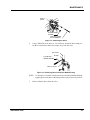
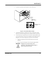
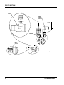
1
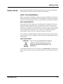
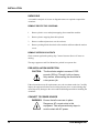
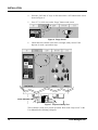
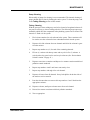
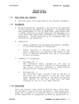
® Accutinter 3200 Series Maintenance Manual Part # 23106 Rev. A 10/23/97 CONFIDENTIAL PROPERTY OF FLUID MANAGEMENT ® (C) COPYRIGHT 1999 FLUID MANAGEMENT AS AN UNPUBLISHED WORK ALL RIGHTS RESERVED This material cannot be copied or disclosed to others without the prior written permission of Fluid Management. Fluid Management® A Unit of IDEX Corporation 1023 Wheeling Road Wheeling, Illinois 60090-5776 Telephone: (847) 537-0880 1-800-462-2466 Fax: (847) 537-5530 TABLE OF CONTENTS INTRODUCTION . . . . . . . . . . . . . . . . . GENERAL SCOPE OF MANUAL HOW TO USE THIS MANUAL SAFETY 5 INSTALLATION . . . . . . . . . . . . . . . . . 11 VERIFY SITE REQUIREMENTS UNPACKING PRE-INSTALLATION INSPECTION CONNECT TO POWER SOURCE INTERFACE CONNECTIONS START UP INITIAL DISPENSE MAINTENANCE . . . . . . . . . . . . . . . . . 17 COVER REMOVAL/INSTALLATION CLEANING LOADING COLORANT LUBRICATION PARTS SECTION . . . . . . . . . . . . . . . . 33 Accutinter 3200 iii iv Fluid Management ® INTRODUCTION INTRODUCTION GENERAL The Accutinter 3200 is a microprocessor-controlled colorant dispenser used for custom-blending of paint. This completely self contained unit is controlled by a built-in computer loaded with ColorPro software. The software is fully menu driven and is designed for ease of use. The software has an “on-line-help” utility that contains information found in the User Manual. Figure 1 shows an overall block diagram of the unit, indicating the interconnection of the various major components. Dispense Control Board If used If used Figure 1. Overall Block Diagram A DC motor (a second motor is optional) drives all the pumps simultaneously with a speed reducer and drive chain. An encoder wheel and magnetic hall-effect sensor provide a known number of electrical pulses per revolution of the motor. These pulses are counted by the dispense control board. Figure 2 is a simplified block diagram of the tinting operation as observed in one colorant. The positive displacement pump delivers a fixed volume of colorant per revolution. From the pump output port the colorant is pushed to the input of a threeway solenoid valve. The valve diverts the colorant to one of two locations: Accutinter 3200 • External container. • Back to the canister which holds the colorant. 5 INTRODUCTION CANISTER VALVE AGITATOR AGITATOR MOTOR PUMP PAINT CAN ENCODER PUMP MOTOR CONTROL SYSTEM Figure 2. Block Diagram of Tinting Operation The colorant in each canister is periodically agitated by a paddle assembly driven by a motor. These agitation motors, located on the bottom of the canisters, are powered by 115 VAC. The entire system runs on 115 VAC. This incoming power is converted to: • 5 volts DC for the electronics (microprocessor and circuit boards) • 24 volts DC for solenoids and relays. A constant-voltage transformer provides 19 volts AC which is converted to a low DC voltage. This power is used to run the pump motor at low speed for recirculation of colorants and low-speed dispenses. The pump is driven at high speed with 130 Volts DC. for high-speed dispensing. The model 3200 Accutinter has a built-in computer that stores the formulas on a hard disk drive. The built-in computer has an externally accessible floppy drive located on the tight side of the machine. 6 Fluid Management® INTRODUCTION SCOPE OF MANUAL This manual provides instructions for installation and scheduled maintenance of the Accutinter. It is intended to be used by service technicians and operators. General knowledge of the operation of the Accutinter is practical when maintaining this equipment. Review the User Manual that came with the Accutinter or refer to the “on-line-help” utility before performing any service procedures on the equipment. This manual is shipped with each Accutinter 3200 along with the following documentation: • The Accutinter 3200 schematic. • The Getting Started with ColorPro Manual. P/N 20936 • The Accutinter Service Guide. P/N 22763 This manual is to be used in conjunction with the other documentation that comes with the equipment. HOW TO USE THIS MANUAL The manual is organized into four (4) sections including this one. Each section is divided into sub-sections that cover a given Accutinter topic. The intent is to provide a basic reference work that can be used to address installation and maintenance issues. SAFETY The Accutinter line of precision colorant dispensers is a safe and effective collection of quality equipment. This equipment is designed to bring many years of operation. In order to avoid damage to the equipment or bodily injury, basic precautions and warnings must be observed. For the Accutinter line, these basic precautions and warnings are accompanied by special labels. Warning Labels There are a number of warning labels on the Accutinter dispenser. Read all of these labels. Keep the labels clean so they are easy to read. If the warning labels become damaged or unreadable, purchase new labels from Fluid Management. See the Parts List section of this manual for ordering information. Safety Information in This Manual Improper maintenance can shorten the life of this equipment. Performing procedures improperly can be hazardous and could result in serious injury or death. The precautions and procedures stated in this manual apply to installers and maintenance personnel. This manual must be read thoroughly before installing or maintaining this equipment. It should be kept near the machine for reference and periodically be reviewed by all personnel who work with the equipment. Some Accutinter 3200 7 INTRODUCTION actions involved in operation and maintenance of the machine can cause serious accidents if they are not performed in the manner described in this manual. Proper precautions must be taken during the maintenance of this equipment. Carelessness and disregard for safety can result in damage to the equipment and injury or even death to the technician. This manual contains statements regarding safety precautions. The precautions are categorized as follows: WARNING: The warning sign indicates that a high probability of serious injury or death exists if the hazard is not avoided. These safety messages describe precautions that must be taken to avoid the hazard. CAUTION: NOTE: A caution is used to signify that precautions must be taken to avoid actions that could damage the equipment. This word is used for information regarding the equipment that may be used by the service technician to make the procedure easier to perform. This equipment uses AC and DC power to operate. AC power can cause injury and even death. Most of the procedures in this manual can and should be performed with the equipment disconnected from the power source. WARNING: There are maintenance procedures detailed in this manual that are required to be performed with the equipment powered. Warnings regarding electrical shock hazards will accompany those procedures. All electrical shock warnings must be heeded to ensure that these maintenance procedures may be performed safely. 8 Fluid Management® INTRODUCTION NOTES: 10 Fluid Management® INSTALLATION INSTALLATION Record the Model Number and Serial Number on the parts section of this Manual. These numbers are located on the back panel of the Accutinter. VERIFY SITE REQUIREMENTS Before you begin the installation procedure, inspect the installation site and ensure that it meets all necessary requirements. If the equipment is installed in an inappropriate site, routine maintenance and service procedures may be difficult to perform. SPACE REQUIREMENTS Ensure that there will be ample space around the installed equipment. Some maintenance procedures require that service personnel have access to the rear of the equipment. If the equipment is placed against a wall, there must be sufficient room to move the Accutinter away from the wall. There must be ample room at the front of the equipment for the operator to move about. The assembled Accutinter is approximately 50 inches (127 cm) wide and 25 inches (64 cm) deep. The Accutinter weighs approximately 1000 pounds (450 kg). Ensure that the floor at the operation site is level, and that it will easily be able to withstand the weight of the equipment. AVAILABLE POWER CAUTION: The use of non-dedicated AC electrical service to the Accutinter may result in improper operation and damage to the equipment. The Accutinter requires 115 VAC at 20 Amps on a dedicated line. Ensure that the power supply is sufficient for the Accutinter and that it meets all national and local codes. Accutinter 3200 11 INSTALLATION UNPACKING A screwdriver and pair of scissors or diagonal cutters are required to unpack the Accutinter REMOVE PROTECTIVE COVERING. 1. Remove plastic cover and nylon strapping from around the machine. 2. Remove plastic wrapping from the keyboard. 3. Remove cardboard protectors over the canisters. 4. Remove packing blocks from back of the machine and from under the canister covers. REMOVE INTERIOR CONTENTS Check contents against the packing slip. Contact Customer Service if items are missing. The surge suppressor and User Manual are packed in a separate box. PRE-INSTALLATION INSPECTION CAUTION: The Accutinter weighs in excess of 1000 pounds (450 kg). Though it rolls on heavyduty casters, maneuvering the Accutinter is a two-person job. If the selected site meets all requirements, move the Accutinter to the site. Carefully inspect the equipment for dents and scratches that may have occurred during shipment. Report any damage to the carrier and Fluid Management before installing the Accutinter. CONNECT TO POWER SOURCE WARNING: Ensure that all covers are in place. Dangerous AC current exists in this equipment. Take all precautionary steps to avoid contact with AC power. 12 Fluid Management® INSTALLATION 1. Plug the single plug surge protector that you received with the machine into a 20-amp dedicated line. 2. Plug the Accutinter and monitor into the surge protector. INTERFACE CONNECTIONS The Accutinter is equipped with a serial interface to connect the dispenser to additional external equipment such as a scale or spectrophotometer color matching system. Connect the peripherals equipment as follows: 1 Connect the serial port located on the left side of the Accutinter to the serial port on the peripherals. 2. Connect electrical power to the peripherals. START UP Once you have connected the Accutinter to AC power, the computer will boot-up and the display will show the ColorPro home page. If an error message appears or the PC does NOT come up running ColorPro, call 1-800-462-2466 for assistance. To prepare the Accutinter for everyday operation, refer to the software section of the Accutinter Service Guide. Spectrophotometer Configuration The model 3200 Accutinter is designed to use a spectrophotometer for color matching functions. The following steps represent the process by which the color matching system is configured in the Accutinter system: 1 With ColorPro running and the main menu open, press “F4” or click once on the “Setup” icon. (1.) Figure 3. Selecting Setup Screen Accutinter 3200 13 INSTALLATION 2. From the next screen, select the “External Data” tab. 3. Select the appropriate color matching system and click on the “Add” button. Follow the prompts as required. Scale Configuration The model 3200 Accutinter is designed to use an external scale for color calibration. The scale configuration is done in FM Text. PREPARING AND FILLING THE CANISTERS Refer to “Canister Layout” in the User Manual before filling the canisters. The Accutinter is shipped with a quantity of colorant in the canisters. Shake or stir (depending on what the manufacturer recommends for their colorant) enough colorant to fill each canister. Each small canister (orange plastic cover) holds six (6) quarts of colorant. Each large canister (red plastic cover) holds five (5) gallons of colorant. These canisters must be filled (nut not overfilled) to capacity for the Accutinter to operate properly. 1. Open the colorant compartments by raising the compartment top covers. NOTE: 2. Pull the cap off each canister, one at a time, and fill with the appropriate colorant until the canister is filled. The “full level.” 3. Fill each of the remaining canisters with colorants. 4. Refer to “COLORANT LEVELS” in the User Manual and change all colorant levels to FULL. NOTE: 14 Make sure that you fill all of the canisters to the “full level” just under the bottom of the deflector shield. If the colorant covers wire of the agitation blade, the canister is overfilled. To ensure accurate results, you must allow the aeration in the colorant to escape. Allow to sit at least 12 hours before proceeding. Fluid Management® INSTALLATION INITIAL DISPENSE Determine if the Accutinter is operating by performing a purge. 1. Place a container under the dispense nozzle as shown below. DISPENSE NOZZLE DISPOSABLE CONTAINER Figure 4. Dispense Test 2. Press “F3” or using the touch mouse, click once on the “Maintenance” icon. as shown in Figure 5. (2.) Figure 5. Selecting Maintains Screen 3. Accutinter 3200 From the screen in Figure 6, press the “Ctrl” and “P” keys or click once on the “Purge” tab with the touch mouse. This will open a new screen. 15 INSTALLATION 4. Press the “Ctrl” and “A” keys or click once on the “All” button on the screen shown in Figure 6. 5. Press “F3” or click once on the “Purge” button on the screen. (3.) (4.) Figure 6. Purge Screen 6. Check that each colorant comes out in a straight, steady stream. If the dispense is erratic, repeat these steps. (5.) GOOD DISPENSE BAD DISPENSE Figure 7. Dispense Quality Test The Accutinter is ready to be put into operation. Refer to the “help screen” or the User Manual before initiating a dispense. 16 Fluid Management® MAINTENANCE MAINTENANCE GENERAL This section of the manual provides information for routine maintenance of the Accutinter. The main focus is on cleaning, maintaining colorant levels and proper lubrication. COVER REMOVAL/INSTALLATION Many of the procedures in this section require the technician to remove and reinstall covers to gain access to components in the Accutinter. This section shows the location of the covers and explains how to remove and replace them. The following illustration shows the three covers that are removed for many of the maintenance procedures. The lower front cover exposes the dispenser motor, power supplies, and fuses. It also permits access to some of the canister agitation motors. LOWER FRONT COVER Figure 8. Lower Front Cover Location Accutinter 3200 17 MAINTENANCE The lower rear cover exposes the relay panel with fuses, valves, pumps, and remaining agitation motors. UPPER REAR COVER SCREWS LOWER REAR COVER Figure 9. Upper and Lower Rear Cover Location The upper rear cover permits access to the dispense control board and built-in computer. All lower covers are secured with captive screws. The screws securing the upper rear cover are not captive. When removing the upper rear cover, retain the screws for reinstallation. CLEANING The long term and reliable operation of the Accutinter is largely dependent upon keeping the system clean. Spills on the surface of the Accutinter or Accutinter sensors should be wiped up as they occur. This section addresses the procedures involved in cleaning and maintaining the cleanliness of the Accutinter and its components. 18 Fluid Management® MAINTENANCE Pump Cleaning Disassembly of pumps for cleaning is not recommended. The internal cleaning of pumps should only be done by flushing the entire system. To clean the pump, refer to the Tubing Cleaning section of this manual. Tubing Cleaning With the passage of time, tubing may need to be cleaned of coagulated colorant. It may not be necessary to remove tubing to do this. The following steps represent a method by which all of the components in the plumbing system can be cleaned. The intent is to “flush out” the system. 1 Find a clean container for each colorant in the system. These containers will be used to store the colorant for later reintroduction back into the system. 2. Dispense all of the colorant from one channel until all of the colorant is gone from the canister. 3. Repeat step number two (2) for each of the remaining channels. 4. Fill one (1) canister with hot tap water and recycle for five (5) minutes. A switch on the relay panel can be used recycle colorant. (See “Recirculation Switch Location” on page 31.) 5. Dispense water into a container and dispose in a manner consistent with local pollution control standards. 6. Repeat step numbers 4 and 5 until water runs nearly clear. 7. Repeat step numbers 4 through 6 for each channel. 8. Dispense all water from all channels. It may be helpful to brush the sides of the canisters to free material. 9. Pour the colorants that were removed in step numbers 2 and 3 back into the appropriate canisters. 10. Dispense colorant, until pure colorant comes from each channel. 11. Discard in a manner consistent with local pollution standards. 12. Test as appropriate. Accutinter 3200 19 MAINTENANCE Canister & Agitator Cleaning The agitators and canisters can be cleaned in one of two (2) ways: • Disassembly. • System Flush. Disassembly & Cleaning 1 Find a clean container for each colorant in the system. These containers will be used to store the colorant for later reintroduction back into the system. 2. Dispense all of the colorant from the channel until all of the colorant is gone from each canister. 3. Lift up and remove the agitation blade assembly. 4. Clean the agitation blade assembly thoroughly in soap and warm water. 5. Discard the water in a manner consistent with local pollution control standards. 6. Clean the canister (in place) thoroughly in soap and warm water. 7. Dispense all water from all channels 8. Pour the colorants that were removed in step 2 back into the appropriate canisters. 9. Purge each colorant, dispense one ounce of colorant from each channel and discard in a manner consistent with local solution standards. 10. Test as appropriate. Nozzle Cleaning The Tubing Cleaning process covered in this section should be used in an effort to clean the valves before the decision is made to replace the nozzle. the following steps represent the process by which a clogged nozzle can be cleared. If you are troubleshooting nozzle problems, you should try cleaning before considering replacement. 1 20 Using a paper clip or similar device, clear the nozzle channel being careful not to score any portion of the nozzle assembly. Do this to each channel that may be effected. Fluid Management® MAINTENANCE NOZZLE PAPER CLIP Figure 10. Nozzle Cleaning 2. Perform the purge operation observing the colorant streams. It may be necessary to repeat this procedure several times before the nozzle is clear. If this does not correct the problem, the nozzle assembly must be changed. 3. If the nozzle is clear, purge the system of air and perform appropriate tests. Valve Cleaning If valve problems persist, it may be necessary to disassemble the valve for cleaning. This section describes a through disassembly and cleaning of the valves. It also explains how the valve can be replaced with a new one. It is a major operation and should be preformed only if the valves have become inoperative. Valves may stop functioning if coagulated colorant prevents the parts from moving. Valves Removal Accutinter 3200 1. Remove power by disconnecting power cord from power source. 2. Place an empty 32-ounce can under the dispense nozzle. Opening a line will cause colorant to drain. 3. Open the lower rear cover exposing the valves. Figure 11 on page 22 shows the location of the valves. 21 MAINTENANCE VALVES Figure 11. Location of Valves 4. Unplug the small power plug from the valve. FAULTY VALVE SOCKET HEAD SCREW POWER PLUG Figure 12. Unplugging Valve Power Connector 5. Using a 3/16″ ball-nose Allen wrench, remove the socket-head screws that hold the faulty valve to the valve bar. The hoses will hold the faulty valve in place. NOTE: 22 Some colorant will drain from the valve and hoses. Have small containers or paper towels handy. Fluid Management® MAINTENANCE FAULTY VALVE SOCKET HEAD SCREW 3/16" BALL NOSE ALLEN WRENCH Figure 13. Removing the Valve 6. Using a flat-blade screw driver or 1/4″ nut driver, loosen the hose clamps on the three colorant lines. Move the clamps away from the valve. TOP HOSE FLAT BLADE SCREW DRIVER CLAMP FAULTY VALVE Figure 14. Removing Hose Clamp from Barbed Fitting NOTE: 7. Accutinter 3200 If a heat gun is available, slowly heat the area around each barbed fitting. Applying heat to the hose at the fitting makes removal easier to perform. Remove all three hoses from the valve. 23 MAINTENANCE HEAT THIS AREA FAULTY VALVE HEAT GUN HEAT THIS AREA Figure 15. Heating the Barbed Fitting NOTE: If you are cleaning or repairing the existing valve, proceed to the next section. If you are installing a new replacement valve, proceed to “Installing the New Valve.” Valves Disassembly USE 3/4" OPEN END WRENCH SPRING LARGE END SMALL END QUICK RELEASE FITTING BARBED FITTING USE ADJUSTABLE WRENCH SOLENOID UES 1" OPEN END WRENCH USE 9/19" OPEN WRENCH ON 90 DEGREE FITTING Figure 16. Exploded View of Valve 1. 24 Remove the 90° fitting from the solenoid (coil). Turn the fitting counterclockwise. Fluid Management® MAINTENANCE 2. Remove the 1″ nut to release the solenoid from the neck of the valve. NOTE: 3. Accutinter 3200 If a spanner wrench is not available, an adjustable wrench may be used: reinsert the 90° fitting and use the wrench on the two flats above the threads on the valve body. Use a spanner wrench to remove the silver neck from the brass valve base. Grasp the valve at the base, but not the end. The two pieces inside the valve are a spring and a viton poppet assembly. 25 MAINTENANCE Valve Cleaning 1. Prepare a solution of soapy water. 2. Clean all parts thoroughly with the soapy water, using a small synthetic brush. 3. Be sure no debris is embedded in the viton seat of the poppet. 4. Check that there are no slices in the poppet, and no pieces missing. 5. Rinse all parts thoroughly with clear water. Valve Reassembly 1. The parts should all be clean and dry. 2. Refer Figure 16 on page 24 to reassemble the valve. Valve Insertion CAUTION: NOTE: 1. Do not cross-thread the screws in the aluminum bar. When installing the valve, be sure that the words “IN” and “OUT” stamped on the brass valve body are placed in the proper direction. The side labeled “IN” should be coming from the pump and the side labeled “OUT” should be going to the dispense nozzle. Install the valve on the valve bar and secure with the two socket-head screws. NEW VALVE SOCKET SCREWS HEAD Figure 17. Installing Valve 26 Fluid Management® MAINTENANCE 2. Verify that the hose clamps are in place on the hose ends before pushing tubing in. 3. If a heat gun is available, heat the hose ends. 4. Push the hoses over the fittings. 5. Tighten the hose clamps. 6. Reconnect the power plug to the valve. WARNING: Dangerous AC current exists in this equipment. Take all precautionary steps to avoid contact with AC power. 7. Restore power to the dispenser, and turn on the recirculation switch so that the pumps are turning at low speed. The recirculation switch is located on the relay panel. 8. Check for leaks around the valve fittings. 9. Turn the recirculation switch off. 10. Manually dispense approximately 5-10 ounces of colorant into a clean container to purge any air introduced into the system. Make sure that the colorant does not flow through the recirculation port. 11. Replace the lower rear cover. 12. Restore power to the Accutinter. 13. Test as appropriate. Accutinter 3200 27 MAINTENANCE LOADING COLORANT NOTE: When filling the canisters with colorant, the recirculation deflector should never be covered. Open one colorant container at a time and pour immediately into the appropriate canister. RECIRCULATION DEFLECTOR MAXIMUM LEVEL Figure 18. Filling Canisters 1. Remove the canister covers from each canister on the Accuitnter. 2. Open one container of colorant at a time. 3. Pour the colorants slowly into the appropriate canisters not exceeding the level defined by the recirculation deflector. 4. Update the colorPro software under the setup icon. CAUTION: If the software is not properly updated, the Accutinter will not function properly. LUBRICATION Oil Level Check And Lubrication The speed reducer connects the shaft of the dispenser motor to the drive chain and pumps. The speed reducer requires very little maintenance provided the oil level is properly maintained. The oil level should be checked periodically, and the level should be maintained if leakage occurs. The oil must be changed each time maintenance procedures are preformed that require gearbox disassembly. 28 Fluid Management® MAINTENANCE Excessive noise or vibration during the recirculation cycle indicates low oil level or worn elements. To check the oil level: 1. Disconnect power to the machine and remove the lower front cover. 2. Referring to the figure below, remove the oil-level plug located above the drive shaft. MOTOR SPEED REDUCER GEAR BOX OIL CHECK HOLE Figure 19. Inspecting Oil Level 3. If oil does not seep out, the level is low, and should be topped up with one of the following lubricants: AGMA #8 Amoco Cyl. Oil No. 680 Cylasstic TK680 Gulf Senate 680 Mobil 600 W Super Cyl. Oil Hector 3000-S 4. Check for leaks at the housing bolts. Tighten bolts if necessary. 5. Replace the dispenser’s covers, and restore power. Chain Lubrication Periodic lubrication of the drive chains is recommended to ensure smooth operation. If the chains are noisy or if they have not been lubricated in a year, perform the following procedure to lubricate the chains. Accutinter 3200 29 MAINTENANCE SOCKET 1/4" ALLEN WRENCH 1/2" WRENCH POWER PLUG 1/2" OPEN END WRENCH ALLEN WRENCH WITH MOTER, POWER BOX & FUSES LUBRICATION OF CHAINS DRIVE CHAINS 1/2" OPEN END WRENCH WITH MOTER, POWER BOX & FUSES REMOVED Figure 20. Chain Lubrication WARNING: Dangerous AC current exists in this equipment. Take all precautionary steps to avoid contact with AC power. 1. Remove the lower front cover and the lower rear cover from the dispenser. WARNING: Keep hands and clothing clear of moving machine parts. 30 Fluid Management® MAINTENANCE 2. Locate the recirculation switch and place it in the ON position. LOCATION OF RELAY PANEL BACK OF ACCUTINTER RECIRCULATION SWITCH RELAY PANEL Figure 21. Recirculation Switch Location 3. As the motor and chains are turning at low speed, carefully spray a chain lubricant on the chains through at least one complete rotation of each chain. 4. It may be necessary to temporarily remove the power supply module to gain access to all the chains. The wires to the module are long enough to leave it plugged in, yet moved far enough away to provide access to the chain. a. Turn the recirculation switch off, and disconnect power from the dispenser. b. Use a 1/2″ open-end wrench to remove the power supply module. WARNING: Dangerous AC current exists in this equipment. Take all precautionary steps to avoid contact with AC power. Accutinter 3200 31 MAINTENANCE WARNING: Keep hands and clothing clear of moving machine parts. 32 c. Restore power and turn the recirculation switch on. d. Lubricate the remaining chains as specified in step 3. e. Disconnect power, and secure the power supply module in place. 5. After lubrication, turn the recirculation switch on for a few seconds. 6. Turn the recirculation switch off, and replace the covers. Fluid Management® MAINTENANCE NOTES: Accutinter 3200 33 MAINTENANCE 34 Fluid Management® PARTS SECTION PARTS SECTION This section is designed to assist you in • Performing service functions and • Identifying parts. All repairs must be performed by qualified service personnel. TERMS: Unless prior arrangements have been made, parts will be shipped UPSCOD. All prices are F.O.B. Wheeling, Illinois, and are subject to change without notice. In all correspondence or phone orders for parts, please state model number and serial number of the Miller Mixer. Order less than $25.00 will be assessed a $5.00 handling charge. RETURNS: No parts are to be returned without prior authorization. A Returned Goods Authorization number is required. Accutinter 3200 33 PARTS SECTION EQUIPMENT MAINTENANCE LOG RECORD MODEL NUMBER HERE: _________________________ RECORD SERIAL NUMBER HERE: _________________________ SERVICE DATE 34 DESCRIPTION & PARTS REPLACED (STATE IF UNDER WARRANTY) SERVICED BY Fluid Management ® PARTS SECTION SPARE PARTS ORDER Fluid Management Parts Order Form Photocopy and use this form to Mail or fax orders to: Fluid ManagementA unit of IDEX | Phone: 1(800) 462-2466 1023 South Wheeling Road | Fax: 1(847) 537-5530 Wheeling, IL 60090 | | Sold To: Ship To: ________________________ ________________________ ________________________ ________________________ ________________________ ________________________ ________________________ ________________________ P.O. Number___________ PHONE # (___)___-____ Ship Via: ______________________ Collect Prepaid QUANTITY PART NUMBER Taxable Tax Exempt (Fax copy of exemption certificate.) DESCRIPTION UNIT PRICE S S S S S S S S S S Comments: ____________________________________________________ ____________________________________________________ ____________________________________________________ _______________________ ________________________ Signature Name (Pease print) Accutinter 3200 ______________ Date: 35 PARTS SECTION MONITOR NOZZLE KEYBOARD TOUCH MOUSE FLOPPY DRIVE QUART SHELF CANISTORS CAN SENSOR CANISTER COVERS MOTOR POWER SUPPLY GEAR REDUCER PUMP MOTOR(S) Figure 22 Location of Major Components Accessible From Front 36 Fluid Management ® PARTS SECTION POWER SUPPLY BUILT-IN COMPUTER DISPENSE CONTROL BOARD PUMPS VALVES Figure 23 Location of Major Components Accessible From Back The remainder of this section illustrates the location of parts along with lists of part numbers. Accutinter 3200 37 PARTS SECTION PUMP BODY S15500 ELBOW FITTING S4600326 ADAPTOR S15625 INTAKE FITTING S03879 COUPLING HALF S03482 38 Fluid Management ® PARTS SECTION PART NO DESCRIPTION NO REQ S03482 PUMP COUPLING HALF (2 PER PUMP) A/R S03879 PUMP INTAKE FITTING, 1” OD X 3/8” NPT (1 PER PUMP) A/R S15550 SLEEVE MOUNTED PUMP, 2GPM (1 PER COLORANT) A/R S15625 PUMP OUTPUT ADAPTOR (1 PER PUMP) A/R PUMP MOTOR (2ND MOTOR OPTIONAL) 1 (2) ELBOW FITTING (1 PER PUMP) A/R S19470 S4600326 Accutinter 3200 39 PARTS SECTION PUMPS PUMP MOTOR S19470 COVER S03301 SPACER S03484 SENSOR S50180 BRUSHES S4100820 MAGNET S50118 CONNECTOR S01367 DISK & HUB S50152 COVER LOCATION MOUNTING BRACKET S50163 BRACKET S01834 TERMINAL S20354 SCREW S03005 CONNECTOR S01312 40 LOCK WASHER S01123 Fluid Management ® PARTS SECTION PART NO DESCRIPTION NO REQ S01123 LOCK WASHER, #6 (1 PWE ENCODER) A/R S01312 ENCODER SENSOR CONNECTOR (1 PER ENCODER) A/R S03484 SPACER (1 PER MOTOR) A/R S03301 COVER (1 PER ENCODER) A/R S01367 ENCODER CONNECTOR (1 PER ENCODER) A/R S03005 SCREW, # 6-32 X 1/4” (1 PER ENCODER) A/R S01834 ENCODER SENSOR BRACKET (1 PER ENCODER) A/R S19470 PUMP MOTOR (2ND OPTIONAL) A/R S50118 ENCODER MAGNET (1 PER ENCODER) A/R S50163 ENCODER BRACKET (1 PER ENCODER) A/R S50180 ENCODER SENSOR (1 PER ENCODER) A/R S4100820 MOTOR BRUSHES 1 SET PER MOTOR) A/R Accutinter 3200 41 PARTS SECTION SET SCREW S12148 SPIDER S01038 KEY S15179 HUB S15603 CHAIN S06393 SPROCKET S65153 SPROCKET S15513 PUMP MOUNT ASSEMBLY S15503 PUMP S15504 (CCW) S15543 (CW) LOCK WASHER S00219 WASHER S00217 SCREW S01119 SPEED REDUCER S06662 MOTOR S19470 42 Fluid Management ® PARTS SECTION PART NO DESCRIPTION NO REQ S00217 FLAT WASHER, 3/8” 4 S00219 LOCK WASHER, 3/8” SPLIT 4 S01038 COUPLING SPIDER (1 PER PUMP) S01119 SCREW, 3/8-16 X 1 1/4” S06393 CHAIN, 1/4” PITCH X 71 LINKS (1 ASSEMBLY PER PUMP, LESS 1) A/R S06662 SPEED REDUCER A/R S12148 SET SCREW, 1/4-20 X 5/16” (2 PER PUMP) A/R S15179 KEY, 3/16 X 1” (1 PER PUMP MOTOR) 1 (2) S15503 PUMP MOUNTING ASSEMBLY (1 PER PUMP) A/R S15504 PUMP, CCW A/R S15513 WELDMENT SPROCKET WITH HUB (1 PER PUMP MOTOR) A/R S15543 PUMP, CW A/R S15603 COUPLING HUB (1 PER PUMP MOTOR) A/R S65153 WELDMENT SPROCKET (1 PER PUMP) A/R Accutinter 3200 A/R 4 43 PARTS SECTION STOP S06488 BRACKET S21995 SHELF S21712 SCREW SF0028C3N10 WASHER S4000326 NUT S4000003 LIGHT BOARD S01178 NUT S4000027 WASHER S01670 NOZZLE S21709 ORPHICE S21710 44 Fluid Management ® PARTS SECTION PART NO DESCRIPTION NO REQ S01670 WASHER, 3/16” ID X 3/8” OD X 1/16” 2 S06488 QUART CAN POSITIONING STOP 1 S01178 BOUNG HOLE LIGHT RESISTOR BOARD 1 S21709 NOZZLE BLOCK S21710 ORPHICE (1 PER COLORANT) S21712 QUART SHELF 1 QUART SHELF MOUNTING BRACKET 2 S4000003 NUT, 1/4-20 2 S4000027 NUT, 10-32 2 S40003262 LOCK WASHER, 1/2” OD. 2 NUT, 10-31 2 21995 SF0028C3N10 Accutinter 3200 1 A/R 45 FLOPPY DRIVE S21599 SERIAL PORT S15385 CAN SENSOR S21700 DISPENSE CONTROL BOARD S16281 FLASH ROM S18809 46 Fluid Management® PART NO DESCRIPTION NO REQ S15385 SERIAL PORT CABLE ASSEMBLY 1 S16281 DISPENSE CONTROL BOARD 1 S18809 FLASH ROM, 256K 1 S21599 FLOPPY DRIVE 1 CAN SENSOR 1 21217 Accutinter 3200 47 POWER SUPPLY S21650 FAN S????? S????? POWER CABLE POWER S21650 SUPPLY S21650 AUX PC PORT S4601346 PORT S21899 DISPENSE CONTROL BOARD S16281 OUTLET S1007266? PROCESSOR BOARD S21716 48 Fluid Management® PART NO DESCRIPTION NO REQ S15995 MICROPROCESSOR 1 S21138 PROCESSOR BOARD 1 S21597 MEMORY BOARD 8 MB (NOT SHOWN) 1 S21650 DUAL VOLTAVE POWER SUPPLY PHONE LINE PORT 1 S1007266 S121899 POWER RECEPTICAL 1 S4601346 MONITOR PORT 1 Accutinter 3200 49 1 2 3 4 5 6 TERMINAL S21408 CONNECTOR S01520 7 8 END BLOCK S5608210 DIN RAIL S21734 9 10 11 12 13 14 15 16 17 18 MONITOR S16378 END PLATE S21413 TERMINAL S21410 FUSE S01791 FUSE S01463 FV1 FV2 FV3 FV4 FUSE S01752 FV5 FV6 FV7 FV8 OUT IN IN OUT KEYBOARD S22452 TOUCH MOUSE S19198 50 Fluid Management ® PART NO DESCRIPTION NO REQ S01463 FUSE,1A @ 250V 1 S01520 POWER INPUT CONNECTOR 1 S01752 FUSE, SLOW BLOW, 3A @ 250V 8 S01791 FUSE, SLOW BLOW, 2A @ 250V 1 S16378 14” COLOR CRT MONITOR 1 S19198 TOUCH MOUSE 1 S21408 TERMINAL BLOCK 8 S21410 TERMINAL BLOCK 1 S21413 TERMINAL BLOCK END PLATE 1 S5608210 TERMINAL BLOCK END BLOCK 2 Accutinter 3200 51 BACK OF ACCUTINTER RELAY PANEL S65217 FUSE 3A SLO BLOW S5108248 HIGH VOLTAGE RECTIFIER S12595 HIGH SPEED SOLID STATE RELAY S6288 RECIRCULATION MOTOR SOLID STATE RELAY LOW SPEED S6288 52 AGITATION & PUMP MOTOR TEST SWITCHES S1717 LOW VOLTAGE RECTIFIER S12595 HIGH SPEED TEST BUTTON S01339 FUSE 15 A, SLO BLOW S06286 AGITATION MOTOR SOLID STATE RELAY S6288 Fluid Management ® PART NO DESCRIPTION NO REQ S01339 PUSHBUTTON (1PER PUMP MOTOR) S06268 FUSE, 15 AMP, SLOW BLOW 1 S1717 TOGGLE SWITCH, SPDT 2 S6288 SOLID STATE RELAY 3 S12595 FULL WAVE BRIDGE RECTOFYER 2 S65217 RELAY PANEL ASSEMBLY 1 S5108248 FUSE, 3 AMP, SLOW BLOW 1 Accutinter 3200 1(2) 53 LIMITED WARRANTY ON EQUIPMENT HARDWARE WARRANTY If within one year from the date of shipment or one year from the proven date of installation, any equipment covered by this manual shall prove to be defective in materials or workmanship upon examination by FLUID MANAGEMENT (“SELLER”), SELLER will supply identical or substantially similar replacement equipment or parts, or at SELLER's option, will repair or allow credit for such equipment. In addition, within the United States and Canada, labor costs are covered for the first six months following shipment or proven installation date for repairs to the following components: crankshafts, motors, speed reducers, circuit boards, relays, relay panels, power supplies, transformers, frames, gear pumps, solenoid valves, canholders, bearings and clutch springs. All labor must be approved in advance by SELLER and performed by a Fluid Management Authorized Service Center. PURCHASER MUST NOTIFY SELLER OF A WARRANTY CLAIM WITHIN THIS PERIOD. NO RETURNS ARE AUTHORIZED WITHOUT A RETURN GOODS AUTHORIZATION FORM. Any repair or replacement provided hereunder shall be warranted against defects in material or workmanship for the unexpired portion of the equipment warranty. This warranty does not cover software, which is covered by separate warranty. Disclaimer THIS WARRANTY SHALL BE APPLICABLE ONLY IF THE EQUIPMENT SHALL BE THE PROPERTY OF THE ORIGINAL PURCHASER OR USER, AND SHALL HAVE BEEN PROPERLY USED, OPERATED AND MAINTAINED IN ACCORDANCE WITH THE MANUAL OR INSTRUCTIONS PROVIDED WITH THE EQUIPMENT AND FOR THE PURPOSE FOR WHICH SOLD. NORMAL WEAR AND TEAR IS NOT COVERED BY THIS WARRANTY. THIS WARRANTY SHALL NOT BE APPLICABLE IF THE EQUIPMENT OR ANY PART THEREOF HAS BEEN REPAIRED OR REPLACED BY THE BUYER WITHOUT THE SELLER'S PRIOR PERMISSION OR HAS BEEN SUBJECTED TO ANY ACCIDENT, CASUALTY, MISAPPLICATION, ALTERATION, ABUSE OR MISUSE. NO OTHER WARRANTY, EITHER EXPRESS OR IMPLIED, AND INCLUDING A WARRANTY OR MERCHANTABILITY AND FITNESS FOR A PARTICULAR PURPOSE, HAS BEEN OR WILL BE MADE BY OR ON BEHALF OF SELLER OR BY OPERATION OF LAW WITH RESPECT TO THE EQUIPMENT AND ACCESSORIES OR THEIR INSTALLATION, USE, OPERATION, REPLACEMENT OR REPAIR. SELLER SHALL NOT BE LIABLE BY VIRTUE OF THIS WARRANTY, OR OTHERWISE, FOR ANY INCIDENTAL, SPECIAL OR CONSEQUENTIAL DAMAGE RESULTING FROM THE USE OR OPERATION OF THE EQUIPMENT, WHETHER OR NOT SELLER WAS APPRISED OF THE POSSIBILITY OF SUCH DAMAGES. IRRESPECTIVE OF ANY STATUTE, THE BUYER RECOGNIZES THAT THE EXPRESS WARRANTY SET FORTH ABOVE IS THE EXCLUSIVE REMEDY TO WHICH IT IS ENTITLED AND WAIVES ALL OTHER REMEDIES, STATUTORY OR OTHERWISE. REPAIR OR REPLACEMENT SHALL BE BUYER'S SOLE REMEDY UNDER THIS WARRANTY. Fluid Management ® LIMITED WARRANTY ON EQUIPMENT SOFTWARE WARRANTY I. FLUID MANAGEMENT (“SELLER”) warrants that it has the right to grant a license for use of the Software included in its equipment. II. SELLER warrants for a period of ninety (90) days from the date of sale of its equipment that the Software will substantially conform with the functionality described in the Manual accompanying the equipment. This warranty is void if a Software error or malfunction is caused by machine malfunction, by modification of the Software or equipment not made by SELLER, or by incorrect data or procedures used by BUYER'S personnel, or if BUYER fails to apply the current release of the Software provided to BUYER. BUYER'S SOLE AND EXCLUSIVE REMEDIES UNDER THIS WARRANTY ARE (1) THE CORRECTION OF THE SOFTWARE SO THAT IT PERFORMS AS WARRANTED (CORRECTION WILL BE BY ERROR MAINTENANCE WHICH MAY INCLUDE THE REPAIR OR REPLACEMENT OF THE SOFTWARE) OR (2) IF, AFTER REPEATED EFFORTS, SELLER DETERMINES THAT IT IS UNABLE TO MAKE THE SOFTWARE PERFORM AS WARRANTED. BUYER MAY RETURN THE EQUIPMENT TO SELLER AT BUYER'S EXPENSE. SELLER SHALL NOT BE LIABLE FOR ANY ACTUAL OR CONSEQUENTIAL DAMAGES INCURRED BY BUYER. III. EXCEPT AS EXPRESSLY STATED IN THIS WARRANTY, SELLER MAKES NO WARRANTIES, EXPRESS OR IMPLIED, CONCERNING THE SOFTWARE, INCLUDING ALL WARRANTIES OR MERCHANTABILITY AND FITNESS FOR A PARTICULAR PURPOSE. Software License 1. SELLER grants to BUYER, subject to the terms and conditions contained in this Software License, a non-exclusive and nontransferable license (except as provided below) to use the proprietary computer software programs and related materials (Software) in association with SELLER's equipment set forth in this Manual. 2. BUYER shall have the right to use the Software solely for its own internal operation at the Location where first placed in operation and on the Central Processing Unit (CPU) described in this Manual. 3. When the CPU is temporarily inoperable, BUYER may transfer the use of the Software to a backup central processing unit until operable status is restored to the CPU. In addition, BUYER may make copies of the Software for purposes of backup only. 4. This Software License is assignable and transferable in connection with the equipment for which this Manual is provided. Proprietary Information 1. BUYER acknowledges that the Software for the equipment set forth in this Manual constitutes proprietary and confidential information of SELLER and that the protection of this information is of the highest importance. BUYER agrees to keep the Software in strict confidence, to take appropriate steps to ensure that persons authorized to have access to the Software shall refrain from any unauthorized reproduction or disclosure of the Software and to restrict access to and display of the Software to BUYER'S personnel who need to access or display the Software to enable BUYER to use the Software as contemplated by this Agreement and who have been advised of and have agreed to treat the Software in accordance with BUYER'S obligations. 2. BUYER will not lend, sell, give, lease or otherwise disclose the Software or any associated programs derived or developed from the Software without the prior express written approval of SELLER. 3. BUYER will not be liable for disclosure of any Software if: 3.1 The information is rightfully known to BUYER prior to receipt of it from SELLER, or 3.2 The information is in or comes into the public domain through no act or omission on the part of BUYER, or 3.3 The information is rightfully disclosed to BUYER by a third party with SELLER's approval and without restriction on disclosure. 4. BUYER agrees that the Software and all copies and versions made by BUYER are and shall remain the sole property of SELLER. BUYER agrees to include SELLER's proprietary notice on all copies of the Software in whole or in part, and in any form made by the BUYER. 5. The obligations set forth in this Agreement shall survive the termination of this or any other Agreement with SELLER. Fluid Management ® ® 1023 Wheeling Road Wheeling, Illinois 60090-5776 Voice (847) 537-0880 (800) 462-2466 Fax (847) 537-5530 Part # 23106 Rev. A 23/23/97