1
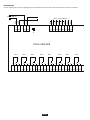
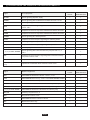
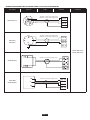
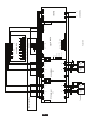
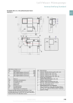
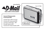
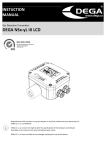
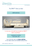
INSTRUCTION
MANUAL
Modular Evaluation Controller
DEGA UMA x Standart Profi
ISO 9001:2008
Quality Management Systems
Systéme de Qualité
www.sgs.com
Content
Page 2 / For your protection
Page 2 / Operational and external conditions
Page 2 / Technical data and information
Page 4 / Accessories
Page 5 / Terminology
Page 6 / Description of the individual modules
DEGA UMA CU/CUL
DEGA UMA 2I/2IL/8I/8IL
DEGA UMA RE8
Page 9 / Description of the signals of the individual modules
Page 10/ Installation, assembly and disassembly of the controller
Page 11/ Connecting the transmitters to the DEGA UMA x Standard Profi controller
Page 12/ Operation and maintenance
Page 13/ Appendices
Page 16/ General warranty terms and conditions
Reproduction of this manual, or any part thereof, in any form, without the prior written permission of DEGA CZ s.r.o.
is prohibited.
DEGA CZ s.r.o. reserves the right to alter the specifications of the hardware and software described in this manual at
any time and without prior notice.
DEGA CZ s.r.o. bears no liable for any damage resulting from the use of this device!
FOR YOUR PROTECTION
Watch out for static electricity
Prior to installing or handling the product, ensure that you do not have an accumulated static charge. Touch a grounded
metal object to trigger the discharge of any accumulated electric charge. Otherwise the product could suffer damage.
In the event of any failure of the equipment unplug it immediately
If you notice an unusual odour or smoke emanating from the product, unplug it from the mains and from all peripherals.
Continued operation could result in injury or property damage. After disconnecting the product deliver it to an authorised
service centre or the manufacturer for inspection.
Do not use the product in the vicinity of flammable gases or
in areas where there is a potential occurrence of these gases.
Do not use electronic equipment in the vicinity of flammable gases; this could potentially cause a fire or an explosion. The
product is not designed for use in industrial or commercial spaces nor in „Ex“ hazardous areas.
Do not disassemble the product and ensure against its contact with water
Contact with internal components of the product may cause an electric shock. In the case of any failure refer the servicing
of the product exclusively to a certified service centre. Contact with water can create a short circuit in the product and
consequent damage to property or personal injury.
Utilise only certified DEGA accessories
The device is certified and is technically and functionally suitable for authentic „DEGA“ accessories. In the event that the
device is utilised with other products the manufacturer shall not liable for any damages that this may cause.
Use cables of the appropriate types
To ensure compliance with the parameters of the product, to connect the product to other devices or to the power supply
utilise exclusively the cables recommended and described in the Technical Data and Information section.
Attention to proper grounding
When connecting the DEGA device inside a metal box, the user is required to connect the 230 VAC (LN PE) supply by
means of a three-core cable with a minimum cross section of 1.5 mm2 and to ground the box with a separate yellowgreen PE conductor with a minimum cross-section of 6 mm2.
OPERATIONAL AND EXTERNAL CONDITIONS ( CSN 33 2000-5-51 )
Operating temperature range:
AA4 (-5 ro + 40°C)
Relative humidity of the ambient air:
AB5 (up to 95% at + 40°C) without condensation
Altitude:AC1
Occurrence of humidity:AD1
The incidence of solid foreign bodies:
AE1
Occurrence of corrosive or pollutant substances:
AF1
Vibration:AH1
The type of materials processed or stored:
BE1
Degree of pollution:2
In terms of the risk of electric shock, in accordance with CSN 33 2000-3 and with CSN 33 2000-5-51 the device is intended for use in no
explosive atmosphere. The modular controller is intended for use primarily in internal spaces and to be either mounted in racks or placed in
DEGA boxes.
TECHNICAL DATA AND INFORMATION
Supply voltage for the controller (source): 230V AC/50 Hz
Supply voltage for the modules of the controller and its accessories: 12 V DC
(DEGA UMA-CU ,DEGA UMA 2I, DEGA UMA 8I, DEGA UMA RE, DEGA UMA AK)
Ingress Protection:IP 20
Degree of interference suppression:Class A
Wire connection:
DEGA UMA CU/CUL, 2I/2IL, DEGA UMA 8I/8IL, DEGA UMA RE8:
screw terminals max. 2.5 mm2
DEGA UMA AK, DEGA UMA TL, DEGA UMA SIG R/G/Y
screw terminals max. 2.5 mm2
PAGE 2
EVERY CONTROLLER IS COMPOSED OF THE POWER SOURCE AND THE FOLLOWING BASIC MODULES:
Processing modules
DEGA UMA CU (the DEGA UMA x Standard evaluation module, i.e. detection levels 1 -2)
DEGA UMA CUL (the DEGA UMA x Profi evaluation module, i.e. detection levels 1 -4)
Power consumption:140 mA
Dimensions (w x h x d)
145 x 128 x 55 mm
Weight:350g
Output ampacity:
60 mA, without protection against short circuiting
Contact outputs:relay, potential free
Voltage and current at the contacts:
250 V AC, 4 A
Material from which the contacts are made:
AgCdO
Setting options (by default the values highlighted are set):
- automatic reset of the acoustic alarm - TA
22s, 45s, 3min., 6min., 12min.
- blocking after the switching-on - TB
22s, 45s, 3min.
- the switching delay of the relay of levels 1 - 4 -TZ
0s, 10s, 20s
Input modules
DEGA UMA 2I /8I (input module for 2/8 transmitters for the DEGA UMA x Standard, i.e. detection levels 1 – 2)
DEGA UMA 2IL /8IL (input module for 2/8 transmitters for the DEGA UMA x Profi, i.e. detection levels 1 -4)
Output ampacity:
60 mA, without protection against short circuiting
Input signal:
DEGA UMA 2IL/ 8IL
4 – 20 mA
DEGA UMA 2I /8I
„Standardised DEGA signal“, i.e. a current signal that can
adopt only three discrete values (with a tolerance of ± 2 mA):
4 mA for a concentration lower than level 1
10 mA for a concentration higher than level 1
16 mA for a concentration higher than level 2
Input impedance:100 Ω
DEGA UMA 2I/2IL
DEGA UMA 8I/8IL
Max. number of transmitters connected
2
8
Power consumption50 mA200 mA
Dimensions (W x H x D)
145 x 128 x 55mm 375 x 128 x 55
Weight:300g600g
Supply voltage for the transmitters: (VDC):
10, 12, 18
10, 12, 18
PAGE 3
ACCESSORIES
The relay module
DEGA UMA RE8 (relay module with 8 relays)
Power consumption:200 mA
Dimensions (W x H x D)
128 x 93 x 45mm
Weight:220g
Contact outputsSPDT, potential-free
The voltage and current on the contacts
250 V AC, 8 A
The auxiliary relay
DEGA UMA RE (auxiliary relay)
Power consumption:25 mA
Dimensions (W x H x D)
15 x 75 x 50 mm
Contact outputsSPDT, potential-free
The voltage and current on the contacts
250 V AC , 8 A
DEGA UMA PORE (auxiliary power relay)
Coil Input:12V DC
Power consumption:50 mA
Dimensions (W x H x D)
18 x 90 x 65 mm
Contact outputs:SPDT, potential-free
The voltage and current on the contacts:
250 V AC , 16 A
Acoustic signalling
DEGA UMA AK II (acoustic signalling of the controller)
Power consumption:max. 15 mA
Dimensions:Ø 33mm x 81mm
Protection from the front:
IP30
DEGA S II (IP20 degrees of protection)
Power consumption:500 mA
DEGA S II IP54 (IP54 degrees of protection)
Power consumption:50 mA
DEGA S ex (sounder for potentially explosive atmospheres)
Power consumption:150 mA
DEGA UMA TL II (reset button for the acoustic alarm)
Dimensions:Ø 30mm x 87mm
Optical signalling
DEGA UMASIG R/G/Y (external optical indicator on the control panel door)
Power consumption:max. 15 mA
Dimensions:Ø 7mm x 29mm
Protection from the front:
IP65
DEGA MR II (krytí IP20)
Power consumption:500 mA
DEGA MR II IP54 (krytí IP54)
Power consumption:250 mA
DEGA M ex (The sounder of potentially explosive atmospheres)
Power consumption:150 mA
DEGA panel S L (backlit LED panel)
Consumption S1:500mA
Consumption S2:1000mA
Consumption L1:1000mA
Consumption L2
:2000mA
PAGE 4
TERMINOLOGY
The modular DEGA UMA x Standard/Profi controller is used for supplying power to transmitters and to evaluate their status. It is
designed as a modular system, which enables the creation of an optimal set for a specific application. All statuses are indicated by
LEDs on the modules. Individual modules are mounted on a DIN rail and are connected by wires and by the DEGA UMA SK5/40 system
cable.
Basic types:
DEGA UMA x Standard (the level 1 - 2 controller for x transmitters; x= the number of transmitters)
DEGA UMA x Profi (the level 1 - 4 controller for x transmitters; x= the number of transmitters)
The capacity of the controller can only be selected in even number units, i.e. DEGA UMA 2 Standard, DEGA UMA 26 Standard etc. A minimum set consists of a controller for 2 transmitters (DEGA UMA 2 Standard or DEGA UMA 2 Profi) and a maximum set consists of a controller
for 620 transmitters (DEGA UMA Standard 620 or 620 Profi DEGA UMA)!
The controller is composed of the following basic modules:
- Source
- DEGA UMA CU processing module (detection levels 1 -2)
- DEGA UMA CUL processing module (detection levels 1 -4)
- DEGA UMA 2I or DEGA UMA 8I input modules for two or eight transmitters (detection levels 1 -2)
- DEGA UMA 2IL or DEGA UMA 8IL input modules for two or eight transmitters (detection levels 1 -4)
Accessories:
DEGA UMA x BOX - A box with a lock for the installation of the controller outside the rack, i.e. on a wall, etc.
(x=the capacity of the controller in accordance with the number of transmitters connected)
DEGA UMA RE8 - the relay module with eight relays used for the power control of the connected appliances if the relay in the DEGA UMA CU/CUL module is not sufficient
DEGA UMA RE - an independent relay used for the power control of the connected appliances
DEGA UMA PORE - an independent power relay used for the power control of the DEGA PANEL S1/L1 (230 V AC) backlit panels
DEGA UMA AK II - the internal acoustic alarm of the controller installed on the DEGA UMA x BOX
DEGA UMA TL II - the internal reset button of the acoustic alarm
DEGA UMA SIG R/G/Y - an external red/green/yellow indicator for the rack doors or for the special DEGA panel on the rack
I/O converter - the converter is used to convert the output signal of the controller to a digital signal.
DEGA VISIO III - for the sake of clarity, we recommend this software to enable the comprehensive and detailed monitoring of the
entire detection system in/from one central location. This software enables the monitoring of both the transmitters and
the entire units, the backup of all the status of all the transmitters with the possibility of tracking their history both
graphically and with the possibility of export of data. The software can be used with the DEGA UMA x Standard/Profi
controller only when using I/O converters.
External acoustic and optical signalling:
DEGA MR II/MY II/MG II/MSL II - Rotating beacon - red/yellow/green/column
DEGA PANEL L1/S1/L2/S2 II - Backlit one-sided or two-sided panel of two possible sizes - 500 x 200 mm or 1000 x 200 mm.
DEGA S II - External sounder
DEGA TL II - External reset button of the acoustic alarm
PAGE 5
DESCRIPTION OF THE INDIVIDUAL MODULES
2
3
UR E
UR E
UR E
UR E
G ND
S IG R
G ND
AK E
III.L E V E L .E
II.L E V E L .E
I.L E V E L .E
R E ADY E
E R R OR E
DEGA UMA-R E 8
27 26 25 24 23 22 21
36 35 34 33 32 31 30 29 28
4
SK
SK
R E ADY
DEGA
UMA U
CU
UMA-C
E R R OR
I.LE V E L ALAR M
II.LE V E L AL
UMApřís
accessories
UMA
luš ens tví
RE2
RE1
Only for
pouze
proUMA-xIL
UMA-xIL
REA
REP
RE3
RE4
III.LE V E L AL
IV .LE V E L AL
DEGA UMA-xI
PE
1
PE
1
ON
39 38 37
T LE
T LE
UC C
UC C
G ND
Source
zdroj
UMA-Z
+
+
IV .L E V E L .E
+
S IG A
+
S IG R
S IG Y
+
+
S IG R
S IG R
TL
S IG G
+
G ND
maximální
zatížení
Output
ampacity
výstupu
100
mA\100 mA
U
MAaccessories
přís luš ens
UMA
– tví
button
sindicator
igná lkyand
a tla
čítko
DEGA UMA CU/CUL
The basis of the system with its output functions and controls for the DEGA UMA 2I/2IL/8/8IL and DEGA UMA RE8 modules. It
includes a summary exceeding relay for the individual alarm levels from all the channels with optical signalling, the output of the
acoustic alarm, signalling the operation of the detector and a summary of the failures of the individual channels of the controller;
it can be fitted optionally with DEGA REP and DEGA REA relays (an acoustic alarm and operation signalling). The triggering of the
acoustic alarm by individual failure levels can be blocked by internal jumpers. For multiplication of contacts on the alarm, DEGA RE1
to DEGA RE2 or to DEGA RE4, it is possible, in the place of the DEGA UMA SIG R indicators, to implement an external DEGA UMA RE8
relay module.
1
2
2
3
3
4
1
5
2
6
3
7
1
8
2
3
1
2
3
1
2
3
1
2
3
9 10 11 12 13 14 15 16 17 18 19 20
DEGA UMA-xI
RE1 - relay switching at detection level 1 of the alarm
RE2 - relay switching at detection level 2 of the alarm
REP - relay switching in the event of a failure of the detection system
REA - relay switching of an external acoustic alarm (by default set at detection level 2)
RE3 - relay switching at detection level 3 of the alarm
PAGE 6
DEGA UMA 2I/2IL/8I/8IL
An input module for transforming the signal from the transmitters. It is supplied as either a two-channel (DEGA UMA 2I/2IL) or
an eight- channel model (DEGA UMA 8I/8IL). In „L“ variant transmitters it can be connected with an output of 4-20 mA and set to
evaluate four levels of alarm; this is applicable to controllers of DEGA UMA x Profi type. For each channel a failure and two levels of
alarm are signalled optically and these are also linked to the external relay switch.
Note: The inputs for the controller can also be configured for the older transmitters of the DEGA series - DEGA DSx and DEGA DBx.
Indicators
s ignálkyalarm
alarm
1R H
+A1
+
ALHE
1R HE
ALAR MH
E R R OR H
-A2
ALAE
1R AE
ALAR MA
E R R OR A
UC C
ON
UC C
G ND
2R AE
-A2
zdroj
source
UMA-Z
-A2
S IG R
2R H
+
2R HE
1R A
+A1
x or UMA-RE8
1R x1Rnebo
UMA-R E 8
relay of
relé
1.slevel
tup.1
S IG R
2R A
x or UMA-RE8
2R x2Rnebo
UMA-R E 8
relay 2.s
of level
relé
tup.2
-A2
+A1
UMA
accessories,
external
U MA
přís luš ens
tví
relay and indicators
externí relé a s ignálky
UR E UMA-C U
+A1
SK
SK
DEGA UMA-xI
Channel
A...
kanál
A...
PE PE
source
zdroj
UMA-Z
. . . ChannelXX
....kanál
1A 2A 3A 4A
1H 2H 3H 4H
DEGA UMA-xI
+1bTransmitter
Ssnímač
6 -4 č.No.
1 1
+UB O UT
1 2 3
snímač
č.No.
X1
Transmitter
S -D
+B
s nímač DE G A
s nímač DE G A
NS x
NB x,NB X -E ,DV ,NB C O 2-I
PAGE 7
DEGA UMA RE8
A relay module with 8 relays for distinguishing the individual alarm levels from the individual channels of the controller.
RE8
RE7
RE6
RE5
RE4
RE3
RE2
UR E
UR E
32 31 30 29 28 27 26 25
34 33
ON
36 35
RE1
1R xE , 2R xE UMA-xI
G ND
G ND
DEGA UMA-CU
DEGA UMA-RE8
UMA-R E 8
1
1
2
2
RE3
RE2
RE1
3
3
1
4
2
5
3
6
1
7
2
8
RE5
RE4
3
9
1
2
3
1
2
RE7
RE6
3
1
2
3
1
2
RE8
3
1
2
3
10 11 12 13 14 15 16 17 18 19 20 21 22 23 24
PAGE 8
DESCRIPTION OF THE SIGNALS OF THE INDIVIDUAL MODULES
DEGA UMA
CU/CUL
DEGA UMA 2I/2IL
DEGA UMA 8I/8IL
optical signalling of power supply
+
+
ERRORx
optical signalling of the individual transmitters for levels 1 and 2
-
+
AlxE
optical signalling of the failure of individual transmitters
-
+
1RxE
output for the external signalling of the individual transmitters for
levels 1 and 2
-
+
2RxE
output for the external relay of the individual transmitters for level 1
-
+
ERROR
output for the external relay of the individual transmitters for level 2
-
+
ERRORE
optical signalling of a summary failure
-
+
READY
output for the external optical signalling of a summary failure
-
+
READYE
optical signalling of an operation
-
+
RE1, 2
output for the external optical signalling of an operation
-
+
I., II., III., IV. LEVEL ALARM
summary relay for levels 1 and 2
-
+
I., II., III., IV. LEVEL ALARME
optical signalling of the switched summary relay for levels 1, 2, 3
and 4
-
+
AKE
output for the external optical signalling of the switched summary
relay of the acoustic alarm
-
+
TLE
output for an external summary acoustic alarm
-
+
1st, 2nd, 3rd, 4th level
relay
input for the reset button of the external acoustic alarm
-
+
Signal
Optional equipment
DEGA UMA
CU/CUL
DEGA UMA 2I/2IL
DEGA UMA 8I/8IL
AlxE
DEGA UMA-SIG R external indicator – levels 1, 2- red
-
+
1RxE
DEGA UMA-RE external relay – level 1 or the DEGA UMA-RE8 module
-
+
2RxE
DEGA UMA-RE external relay – level 2 or the DEGA UMA-RE8 module
-
+
ERRORE
DEGA UMA-SIG Y external indicator of a summary failure - yellow
+
-
READYE
DEGA UMA-SIG G external indicator of the operation - green
+
-
I., II., III., IV. LEVEL ALARM
DEGA UMA-SIG R external indicator for the summary relay
+
-
RE3, RE4
Summary relay for levels 3, 4
+
-
REA
Relay for the acoustic alarm
+
-
AKE
DEGA UMA-AK external acoustic indicator
+
-
REP
Operational Failure relay
+
-
TLE
DEGA UMA-TL the external reset button of the acoustic alarm
+
-
Signal
Basic equipment
ALARM
PAGE 9
INSTALLATION, ASSEMBLY AND DISASSEMBLY OF THE CONTROLLER
The controller is designed for mounting on a DIN rail in a rack or in the DEGA box. At the customer’s request, it is possible to supply
the indicator panel for mounting on the door of the rack.
DEGA gas detection transmitters of the following types may optionally be connected to the device:
a) the gas detection transmitter of the DEGA NBx-yL II type
is a linear transmitter communicating by means of an analogue current loop 4-20 mA. It is supplied in versions designed for the
detection of natural gas (methane), propane-butane (butane), carbon monoxide (CO), combustible gases, carbon dioxide (CO2) and
more than 100 other gases in accordance with the customer’s requirements.
b) the gas detection transmitter of the DEGA NSx type
with a semiconductor sensor communicating by means of a 4-20 mA current loop. It only transmits information in regard to two
concentration levels. These transmitters are suitable for industrial and also potentially explosive atmospheres („Ex“ zone 1).
c) the DEGA NSx-CL, DEGA NSx-EL, DEGA NSx-IL
are linear transmitters for use in potentially explosive atmospheres („Ex“ zone 1), communicating through an analogue 4-20 mA
current loop. They are supplied in versions for the detection of natural gas (methane), propane-butane (butane), carbon monoxide
(CO), combustible gases, carbon dioxide (CO2) and more than 100 other gases, in accordance with the customer’s requirements.
d) the DEGA DV/DV-T/DV-Tc/DV-TTc transmitter
is a special version of the transmitters (probes) that monitor the concentration of ammonia in water. Utilised for a 2-level detection.
e) transmitter of the DEGA DSx / DBx /NBx type of an older provenance
PAGE 10
CONNECTING TRANSMITTERS TO THE DEGA UMA x Standard/Profi CONTROLLER
Transmitter
Terminal
2
Shielded 3 x 1 mm2 (max. length 300m)
Shielded 3 x 1.5 mm2 (max. length 1100m)
1
5
DEGA NBx-yL II
3
C+
DEGA DSx
DEGA NSx
Cable
4
Terminal
Controller
1A..H
2A..H
3A..H
4A..H
Shielded 3 x 1 mm2 (max. length 300m)
Shielded 3 x 1.5 mm2 (max. length 1100m)
B+
S
D-
1A..H
2A..H
3A..H
4A..H
DEGA UMA 2I/2IL
DEGA UMA 8I/8IL
Shielded 2 x 1 mm2 (max. length 300m)
DEGA NBx-E(L)
1
DEGA NZV
DEGA NBCO2-I
Shielded 3 x 1 mm2 (max. length 300m)
2
1A...H
2A...H
3A...H
4A...H
3
PAGE 11
OPERATION AND MAINTENANCE
1.OPERATION
This compact controller does not require any special maintenance during operation. The surface can be cleaned with a cloth as
needed.
2.MAINTENANCE
For proper operation of the detection system (which also includes the controller) it is requisite to periodically undertake specifically
the following servicing of the transmitters connected to the controller:
a) calibration at least once every 6-12 months (i.e. setting the detection limits, checking the responsiveness of the sensor, checking
the system’s functionality). The precise interval is dependent on the level of contamination of the environment, the degree of
accuracy required and the level of occurrence of the selective gases in the environment.
Calibration should be carried out only by authorised service centres holding a valid certificate of competency or by the manufacturer.
b) „Functional checking“ at least once every 3-12 months. Functional checks are performed utilising the test gas at the concentration
that is intended for it – this must not exceed the limit range of the transmitter. We recommend gases with a certified 1st grade of
purity!
Recommendation: For ideal functioning it is recommended to carry out the calibration and the functional checks once every 6
months or the calibration once every 12 months and the functional check once every 3 months.
The means for testing the fire alarm transmitters must not be utilised for these checks!
PAGE 12
APPENDICES
No.1 A sample block diagram of the detection system
Illustrated as an example of maximum configuration is the connection of the detector with the DEGA UMA 4 STANDARD controller,
consisting of a power source, the DEGA UMA CU output module and two DEGA UMA 2I input modules with connected transmitters.
Four transmitters have been selected for the purpose of illustration. For each transmitter alarm levels 1 and 2are indicated by the
DEGA SIG R indicator lights that activate the outputs to which the individual DEGA UMA-RE8 relay modules are connected. Used for
the power supply is URE voltage supplied by the DEGA UMA CU module. This module summarises the signalling of alarm levels 1
and 2 through a connection between the DEGA SK5 system cable and input modules and it switches the contacts to the relay at the
level 1(RE1) and level 2 (RE2). It also summarises any failure messages and switches the contacts of the DEGA UMA REP operation
relay. The DEGA UMA REP and DEGA UMA REA relays (for the acoustic alarm) are included in the accessories of the controller as
also are the external optical signalling of levels 1 and 2, DEGA UAM SIG G, failure, DEGA UMA SIG Y and the DEGA UMA AK sounder
with a DEGA UMA TL reset button for resetting the alarm. For all external elements it is necessary to check the polarity of the power
supply; the DEG AUMA SIG A and DEGA UMA SIG R indicators of the RE1 and RE2 summary relays (in the DEGA UMA-CU module)
are powered by URE.
No. 2 Installation of the detection system in garages
This diagram shows a small-scale detection system for garages. Its general principles are also applicable to other situations.
The four transmitters are divided into two pairs. The Group 1 transmitters are controlled via relay RE1 and the power relay, e.g. the
ventilation in one floor of garages; Group 2 is solved in a similar manner. A summarising signal of level 1 is provided by the parallel
connection of outputs in the group. The dashed line on the coil of relay RE1 suggests the possibility of connecting the coil of an
additional relay if multiplication of the contacts for signalling to the fire alarm system is required. External relay coils are powered
by URE supplied by the DEGA UMA CU module. Attention must be paid to the correct polarity: + A1, -A2!
The function of the DEGA UMA CU module is to summarise the reports emanating from the input modules. The level 1 output relay
(RE1) is not utilised because of the manner of grouping of the transmitters. Level 2, which controls the lighting boards, is summarily
assessed using the RE2 relay. Level 2 also switches the DEGA MR II beacon via an external RE3 relay. Terminal 30 of the DEGA UMA
CU module, which in other instances is used for switching the optical signalling, is used as the output. Provided that the power
source is sufficient, beacons can be placed in parallel up to a total number of 15 items per single relay contact.
PAGE 13
+
+
ALAR MA
E R R OR A
+
B
Transmitter
S níma č
NB x
Transmitter
snímač
č.1
No.1
NS x
Transmitter
snímač
č.2
No.2
+
A
B
PE
PE
(1)
DEGA U MA-2I
A
ALAR MB
1
2
K
UC C
G ND 19
18
17
E xternísignalling
s igna liz a ce
External
ON
S IG R
2 . s t. 16
1.s t. 15
s ig. 14
IN
E R R OR B
+1b
6S
-4
K
SK
K
ON
G ND 19
18
17
+
(2)
A
snímač
Transmitter
č.3
NB CNo.3
O 2-I
NZV
1 2 3
+
A
DEGA U MA-2I
UC C
ALAR MA
PE
PE
1
2
S IG R
3
4
5
6
S IG R
2 . s t. 16
1.s t. 15
s ig. 14
IN
2 . s t. 13
1.s t. 12
s ig. 11
7
8 IN
9
10
+B
S
-D
E R R OR A
3
4
5
6
+
S IG R
E R R OR B
+
B
B
2 . s t. 13
1.s t. 12
s ig. 11
K
7
8 IN
9
10
NB x-E
Transmitter
snímač
No.4
č.4
+UB
OUT
ALAR MB
R3
R4
R5
R6
DEGA U MA-R E 8
G
R E 1 32
R E 2 31
30
29
28
27
26
R E 8 25
R7
R8
SK
K
RE1
G ND 39
38
37
IV .L E V E L AL AR M
III.L E V E L AL AR M
II.L E V E L AL AR M
TL
RE3
ON
I.L E V E L AL AR M
E R R OR
R E ADY
UC C
RE2
RE4
RE6
+
+
+
+
+
S IG
S IG
S IG
S IG
S IG
G
Y
R
R
A
RE5
RE7
1.s t.
RE1
2.s t.
RE2
P rov.
REP
Akus t.
REA
DEGA U MA-C U
RE8
1 2 3 4 5 6 7 8 9 10 11 12 13 14 15 16 17 18 19 20 21 22 23 24
R2
UR E
36
35
R1
34
33
G ND
P říloha 1
Appendix 1
27
26
25
G ND
24
23
22
21
UR E
K
UC C
230V /50H z
PE
ZDROJ
SOURCE
U MA-Z
L N
G ND
14
13
12
11
10
1
2
36
K v it. a k .
35
P rov. 34
P or. 33
1 . s t. 32
2 . s t. 31
Akus t. 30
29
28
3
4
5
6
7
8
9
10
11
12
13
14
9
8
7
6
5
3
4
PAGE 14
ON
Transmitter
PAGE 15
Transmitter
snímač
No.2č.2
Groun 1
Transmitter
snímač č.1
No.1
relay
group 1 level 1
Transmitter
snímač
No.4 č.4
Groun 2
Transmitter
snímač
No.3 č.3
relay
group 2 level 1
DEGA MR II +
DEGA T
-
Příloha 2
Appendix 2
DEGA PANEL S1/S2/L1/L2
(12V DC)
+
L
N
PE
SOURCE
ZDROJ
GENERAL WARRANTY TERMS AND CONDITIONS
When following the instructions for installation, operation and maintenance, the manufacturer guarantee 24 months from
the date of receipt for the product. Should the product purchased be put into operation by an entity other than the seller, the
warranty period commences from the date that the product is put into operation, provided that the buyer ordered its commissioning
within three weeks of its receipt. The customer expressly acknowledges that during the warranty period that extends beyond the
length of the warranty period that is specified in the Commercial Code (the statutory warranty) s/he can neither require replacement
of the product nor may s/he withdraw from the contract.
1. When claiming a product defect it is necessary to submit a proof of purchase that contains the following information: name and
surname, name and business name, address and the warranty card, if the buyer received one from the seller. The validity of the
warranty shall not be affected by non-compliance with the obligations related to the issuance of the warranty card.
2. Claims concerning the product (for a warranty repair only complete devices are accepted) may be filed during the warranty
period only with the seller from which it was purchased; subsequently the seller is required to forward the product to an
authorised service centre or to the manufacturer.
3. A condition for the recognition of the rights under the warranty is the installation of the product having been undertaken by an
authorised person in possession of a valid certificate from the manufacturer.
4. This warranty is not applicable to:
- a product that has not been put into operation by the manufacturer or by a certified employee in possession of a valid
certificate issued by the manufacturer ,
- damage caused by fire, water, static electricity, power surges in the electric supply or in the public network, accident, improper
use of the product, wear and tear
- contamination of the product and its subsequent cleaning,
- damage caused by improper installation, any adjustment, modification or improper manner of use inconsistent with the
instruction manual, the technical standards or the applicable safety regulations in the Czech Republic,
- damage to the product during transportation caused by improper handling or handling of the product in a manner contrary to
the advice provided in the instruction manual,
- DEGA products that have been used in association with other than original DEGA products, including consumables and
accessories,
- bearing additional parts or consumables (e.g. a foil label, seal, etc.), that are detrimental to normal wear and tear during
operation, together with wear and tear of the product and its parts caused by their normal use.
5. Claims regarding a product defect that can be dealt with reasonably quickly and without additional consequences will be
resolved by remedying the defect (repair) or by replacement of the product part , because in such a case it is a contradiction of
the standard norms that the entire product shall be replaced (§ 616, paragraph 4 of the Commercial Code).
6. The buyer who exercises the right of warranty repair is not entitled to the return of the parts that have been replaced.
7. The warranty period can be extended for up to 48 months and its validity can be extended beyond the standard length on the
basis of the conclusion of an individual warranty contract. Further information may be obtained through a specific business
meeting.
8. For the complete version of the general business conditions and of the claims procedure go to www.dega.cz
Manufacturer: DEGA CZ s.r.o., K Žižkovu 640/9, 190 00 Prague 9, Czech Republic
Tax ID: CZ 279 029 43, Company ID: 279 02 943; Telephone (cz) : +420 774 447 660-5, Fax: +420 227 203 512
E-mail: [email protected] , Web: www.dega.cz
© 2012 DEGA CZ S.R.O.
USER MANUAL VER.: 07DEGAUMA201210
PAGE 16