1
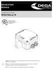
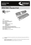
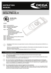
INSTUCTION MANUAL Gas Detection Transmitter DEGA NSx-yL III LCD Reproduction of this manual, or any part thereof, in any form, without the prior permission of DEGA.CZ s.r.o. is prohibited. DEGA CZ s.r.o. reserves the right to alter the specifications of the hardware and software described in this manual at any time and without prior notice. DEGA CZ s.r.o. bears no liable for any damage resulting from use of this device. Content For your safety .............................................................................................................................. Chyba! Záložka není definována. Technical data and information .................................................................................................... Chyba! Záložka není definována. Operational conditions ................................................................................................................. Chyba! Záložka není definována. Terminology .................................................................................................................................. Chyba! Záložka není definována. Product description....................................................................................................................... Chyba! Záložka není definována. Instalation, assembly and disassambly of the transmitter ........................................................... Chyba! Záložka není definována. 1. Assembly of the transmitter ................................................................................................................................................. 5 2. Replacement of the sensor module .................................................................................. Chyba! Záložka není definována. 3. Replacement of the battery .............................................................................................. Chyba! Záložka není definována. 4. Connecting the transmitter via current loop to the the controler DEGA UPA II DEGA UPA III a DEGA UDA III ......... Chyba! Záložka není definována. 5. Connecting the sensor via RS485 to the controller DEGA UPA III/UDA III ............................................................................ 7 6. Installation of wiring for RS485 ......................................................................................... Chyba! Záložka není definována. Selecting the appropriate type of cable depends on the fire report and the protocol for determining external influences .................................................................................................................................................. Chyba! Záložka není definována. 7. Setting the RS485 adress of the transmitter......................................................................................................................... 7 8. Terminating resistor.......................................................................................................... Chyba! Záložka není definována. 9. Communicaton protocol switch DEGA/MODBUS ............................................................. Chyba! Záložka není definována. Transmitter fuctions ..................................................................................................................... Chyba! Záložka není definována. 1. Turning on the transmitter ................................................................................................................................................... 8 2. Gas detection ........................................................................................................................................................................ 8 3. Malfunction ....................................................................................................................... Chyba! Záložka není definována. 4. Monitoring the calibraton periods.................................................................................... Chyba! Záložka není definována. 5. Reading the record of measured concentrations and alarms .......................................... Chyba! Záložka není definována. Transmitter controls ......................................................................................................................................................................... 8 1. History menu „HIST“ ............................................................................................................................................................. 9 2. Information menu „INF“ ..................................................................................................................................................... 10 3. Settings menu „SET“ ........................................................................................................................................................... 11 4. Test menu „TEST“ ............................................................................................................................................................... 13 Operation, maintenance, inpection and service of the transmitter ............................................................................................... 13 1. Usage limits ......................................................................................................................................................................... 13 2. Operation ............................................................................................................................................................................ 14 3. Operation/Maintenance ..................................................................................................................................................... 14 Accessories and basic types of transmitters ................................................................................................................................... 14 1. Calibration adapter / connection to the gas pump DEGA GAS INLET ................................................................................. 14 2. Cover against splashing water DEGA WATER CAP .............................................................................................................. 14 3. Funnel for gas collection DEGA COLLECT CAP .................................................................................................................... 14 4. Additional Ex „d“ DEGA BUSHING ....................................................................................................................................... 14 Basic types of transmitters ............................................................................................................................................................. 15 1. Transmitters with a catalytic sensor NSx-CL III LCD ............................................................................................................ 15 2. Transmitters with an electrochemical sensor NSx-EL III LCD.............................................................................................. 15 3. Transmitters with an infrared sensor NSx-IL III LCD ........................................................................................................... 16 4. Transmitters with a semiconductor sensor NSx-SL III LCD ................................................................................................. 16 Attachments.................................................................................................................................................................................... 17 1. Chart for setting the transmitter adress ............................................................................................................................. 17 2. Table of error codes ............................................................................................................................................................ 18 2. Signalization transmitted by the current loop 4-20 mA .................................................................................................... 18 General warranty terms and conditions ......................................................................................................................................... 19 For your safety Beware of static electricity Electronic components are sensitive to static electricity. Do not touch them directly - they may get damanged. The device is intended to be installed by a trained person 2 The product is designed for installation only by a certified technician. The manufacturer is not liable for damages resulting from incorrect or improper handling. In case of malfunction, immediately unplug from the power supply If you notice an unusual smell or smoke emitting from the product, unplug it from the power supply, battery backup and all other attachments. Continued operation could result in injury or property damage. After disconnecting, have the device inspected at an authorized dealer or manufacturer. Do not open the transmitter and do not replace the sensors in the transmitter in a potentially explosive atmosphere Opening the cover and replacing the sensor in the transmitter in a potentially explosive atmoshpere can cause an explosion. If service is necessary, first unplug the device from the power supply. After that the device may be disassembled and the sensors may be replaced. Do not disassemble the product and ensure against it's contact with water Contact with internal components of the product may cause an electric shock. In case of any malfuction entrust the servicing of the product exclusively to a certified service centre. Contact with water can create a short circuit in the product and consequent damange to property or personal injury. Use appropriate cable types To ensure compliance with the parameters of the product, only use cable types recommended in this guide. Dispose of used products and trasmitter sensors with respect to the environment Transmitter sensors contain hazardous substances. Dispose of them in accordance with the current legislation on environmental protection. Use the transmitter only with the appropriate certified DEGA products The device is certified as functionally and technically qualified only with original "DEGA" accessories. In case of using the device with any other products the manufacturer is not liable for any damages that may occur. Undertake regular functional checks and calibrations of the transmitter Perform regular "CALIBRATION" (setting the detection limits, checking the responsivness of the sensor, checking the functionality of the transmitter) and "OPERATIONAL AND FUNCTIONAL CHECKS" of the entire detenction system (sensor excitation with subsequent control of optical and audible alarms, triggering fans, shutdown technology, etc.). Perform calibration and operational and functional checks only at certified service centers with a valid certificate of competence or the manufacturer. Warning: The transmitter automatically checks it's calibration period - the period of validity of it's calibration. After 12 months since the last calibration (Max. calibration period) the transmitter will transmit this fact to the host system. The transmitter must be calibrated immediately at a certified service center with a valid certificate of competance or the manufacturer. See section "Monitoring the calibration peridos". Technical data and information Supply voltage: Cable connections via 4-20 mA: 24 V nominal, operational range 8-30 V shielded cable 3 x 1 mm (max. 1200 m) shielded cable 3 x 1,5 mm (max. 2400 m) Cable connections via RS485: shielded cable 4 x 0,8 mm (max. 1200 m) - see section “ instalation of cabeling for RS485“ Output: 4 - 20 mA RS485 - protocol DEGA, or MODBUS Communication speed of RS485: Functional safety EN61508: 9,6 kB SIL 2 Marking according to ATEX: II 2 G Ex d IIB+H2 T6 Gb Tamb:-40°C-+60°C II - class environment - non-mining environment 2 G - explosive atmospheres - zone 1 Ex d - type of protection - flameproof enclosure „d“ IIB+H2 - gas group T6 - temperature gas group Gb - type of protection according to EPL Tamb - operating temperature range Dimensions without bushings: Weight: 150x170x65 mm (WxHxD) 2,1 kg 3 Capacity of the internal memory of history: 44 days at 60s recording interval Interval record storage memory: 60 s (adjustable range 1-255 s) Consumption/input at 24V (output RS485) DEGA NSx-EL III LCD 45 mA/1,1 W DEGA NSx-CL III LCD 90 mA/2,2 W DEGA NSx-IL III LCD 70 mA/1,7 W DEGA NSx-SL III LCD 90 mA/2,2 W Consumption/input at 24V (output 4-20mA) DEGA NSx-EL III LCD 65 mA/1,6 W DEGA NSx-CL III LCD 110 mA/2,7 W DEGA NSx-IL III LCD 90 mA/2,2 W DEGA NSx-SL IIU LCD 110 mA/2,7 W Response time (T90) DEGA NSx-EL III LCD max. 180 s - based on sensor type DEGA NSx-CL III LCD max. 15 s DEGA NSx-IL III LCD max. 15 s DEGA NSx-SL III LCD max. 30 s Warm-Up time DEGA NSx-EL III LCD max. 180 s DEGA NSx-CL III LCD max. 30 s DEGA NSx-IL III LCD max. 15 s DEGA NSx-SL III LCD max. 180 s Time to stabilize (>5day without power) DEGA NSx-EL III LCD Up to several hours - based on sensor type DEGA NSx-CL III LCD max. 1 h DEGA NSx-IL III LCD max. 30 min DEGA NSx-SL III LCD max. 5 h Sensor lifetime in a clean environment DEGA NSx-EL III LCD 1-3 years DEGA NSx-CL III LCD 3-6 years DEGA NSx-IL III LCD 5 + years DEGA NSx-SL III LCD 3-6 years Operational conditions Ambient temperature: Relative humidity: Air pressure: -40°C to +85 °C 0-95 % RH 86 - 108 kPa Flow of ambient air: Protection level with a cover: Location: max. 2 m/s - flow directly to the sensor in not allowed IP 64, with a DEGA WATER CAP IP66 cover BE3N2 - explosive atmoshpheres - zone 1 (2 G) Terminology The marking system for sensors DEGA NSx-yL III LCD: Gas sensor DEGA NSx-yL III LCD Series of detectors in potentially explosive atmospheres Type of detected gas Sensor type with linear output Third generation product with new DEGA design Versions with an LCD display DEGA NSx-EL III LCD with an electrochemical sensor They operate on the principle of change of electrical parameters on the electrodes stored in electrolyte, due to oxidation/reduction reactions of the detected gas on it's surface. These sensors have good selectivity and the ability to detect very low concentrations of toxic gases. DEGA NSx-CL III LCD with a catalytic sensor (Pelistor) They operate on the principle of catalytic combustion - gas concentration is measured based on the amount of heat released in a controlled combustion reaction. The reaction is supported by a suitable temperature and the pressence of a catalyst. These sensors can be used to detect a broad range of flammable gases. The sensors are characterized by fast response,a long lifetime and high stability. A minimum of 10% of Oxygen in the air is required for it's proper function. DEGA NSx-IL III LCD with an infrared sensor (NDIR) Top quality scanning method. They operate on the principle of infrared spectroscopy. The sensors have excellent selecivity in organic matter, do not require any oxygen in the atmoshpere and are resistant to catalyst poisons (sulfur and silicon compounds) which cause a change of sensitivity of catalytic sensors. The sensors are characterized by high stability and a long lifetime. DEGA NSx-SL III LCD with a semiconductor sensor Cheapest method of scanning. They operate on the principle of changes in electrical conductivity of semiconductors by changing the concentration of the detected gas. Their advatage is a long lifetime in a clean environment and a wide range of different types of gases and vapors. Their disadvatage is their low selectivity - the sensor largly responds to other gases for which it is not calibrated. 4 Other types: DEGA NSx-yL III basic version DEGA NSx-yL III LCD RE - with an LCD display and a quad relay DegaConfig - sensor adjusting software enabling it's full configuration and calibration. Product descritpion Magnetic control „BACK“ IrDa interface 2 9 Body of the removable sensor 10 0 1 Mounting holes 2 PCB electronics 3 Ex „e“ bushing 4 5 Body of the removable sensor 6 Power supply terminal block+24V DC 7 Power supply terminal block GND 8 17 Battery CR2032 18 DIP switch for the RS485 adress 19 Programming connector 20 21 Status LED 22 Calibration jumpers 1 5 6 Magnetic control „FRONT“ OptionalEx „d“ bushing 3 Ex „d“ bushing 4 7 Body of the removable sensor 8 Ex „e“ bushing 11 0 Cover against splashing water (optional accessories) Magnetic control „ENTER/EXIT“ Cover against splashing water (optional accessories) Optional Ex „e“ bushing Signal terminal block 4-20mA LCD display connector Instalation, assembly and disassembly of the transmitter Before assembling, read the valid instalation standarts EN 60079-29-2 (Selection, instalation, use and maintenance of detectors for combustible gases and oxygen) and EN 45544-4 (Guildelines for the selection, installation, use and maintenance of detectors of toxic substances). In explosive environments the electrical installation must be performed according to DIN EN 60079.14 (Electrical instalation in hazardours areas) 5 Secure that the sensor is reachable by air. The transmitter must be in a free area with no obstacles in its way (furniture etc.) Ensure that the input of the sensor cannot be polluted by layers of dust or other contamination. 1. Assembly of the transmitter The transmitter consists of four parts - the body of the transmitter, the removable sensor and Ex „d“ bushings. Transmitter assembly procedure is as follows: a) Disassemble the transmitter with the four hexagon socket screws 4mm b) Disconnect the LCD motherboards c) Mount the transmitter on a flat surface with four 6mm fasteners in height above the floor with the gas entrance facing downwards, as specified by the detected substance d) Direct the cable trough the bushing e) Connect the cabeling to the terminal block. When using the second Ex „d“ bushing, dismout the Ex „d“ blind plug. It is allowed to use only Ex „d“ bushings with M20x1,5 threads f) Connect the LCD g) Assemble the transmitter with the four hexagon sockets scews 4mm 2. Replacement of the sensor module This activity must not be performed when the sensor is energized. In case of need to replace the sensor module with a new piece, unscrew and remove the cover. Disconnect the sensor module cable from the PCB (1), loosen the sink screw (2) and unscrew the steel cylinder with the sensor (3). Screw the new sensor module, retain it with the sink screw and connect the cable to the PCB. Finally, mount the cover and connect to the power supply. 3. Replacement of the battery Životnost baterie ve snímači je asi 5 let. Po této době již nemusí být některé funkce detektoru zachovány. Baterii vyjmeme z držáku a nahradíme ji typem Panasonic BR2032. Výměnou baterie ve snímači, který není pod napájením, dojde k vymazání interních hodin. 4. Connecting the transmitter via current loop to the controler DEGA UPA II DEGA UPA III a DEGA UDA III Connect one transmitter to each channel of the controler as shown in the picture below 6 5. Connecting the sensor via RS485 to the controller DEGA UPA III/UDA III 6. Installation of wiring for RS485 Wiring must be done using bus topology and according to the RS485 principles. Maximum number of connected transmitters per controler channel is 16 (may be less depending on the configuration of the controller), while the total length of the connecting cable (electrical distance between the controller and the last transmitter) should not exceed 1200 meters. Due to voltage disposals caused by each transmitter, the maximum addition of distances must be L1+L2+L3+…+L16: Cable type NSx-CL III LCD NSx-IL III LCD NSx-SL III LCD NSx-EL III LCD Shielded 4x0,8mm 1,7 km 2,3 km 2,3 km 3,4 km Shielded 4x1mm 2,7 km 3,5 km 3,5 km 5,2 km Shielded 4x1,5mm 4,9 km 5,9 km 5,9 km 9,2 km Shielded 4x2,5mm 8,1 km 10,9 km 10,9 km 16,2 km Selecting the appropriate type of cable depends on the fire report and the protocol for determining external influences. 7. Setting the RS485 adress of the transmitter Each transmitter must have a unique adress within the entire bus, otherwise there will be communication collisions and malfunctions. The transmitter adress can either be set internally using the DegaConfig program or using the DIP switch on the PCB. If the position 6 (labeled ADD) is in the ON position, then the adress according to the setting of pins 1-5 is considered. Otherwise the adress set in DegaConfig is considered. The adress can be set from range 1-31 using binary values. A table with DIP settings for individual adresses is listed in the attachment "Chart for setting the transmitter adress" 8. Terminating resistor According to the RS485 specifications, the last device on the bus must be ending with a terminating resistor 120R. Plug a jumper on the JP2 connector of the last device on the bus to include the 120R terminating resistor. In the default configuaration the jumper connector is not plugged. 9. Communication protocol switch DEGA/MODBUS Plugging a jumper in the JP1 connector will swtich from the DEGA communication protocol to the MODBUS communication protocol. Transmitter functions The detector's motherboard is equipped by status LEDs, which help in detecting problems during the installation. LED „POW“ shines at correct power LED „TxD“ flashes when transmitting a packet via RS485 LED „RxD“ flashes when a packet is correctly recieved via RS485 LED „ERR“ shines/flashes in case of malfunction or substandart situations 7 1. Turning on the transmitter After turning on the power the LED "POW" starts shining and the LED "ERR" starts flashing, indicating a forming sequence of the sensor and automatic testing procedures, which can take up to 180s depending on the sensor used. The output of the current loop is 1mA. During this sequence, testing of internal electronics and stabilization of the sensor in order to eliminate false alarms after turning on, is taking place. At this time, the display only shows the time to the beginning of the measurement loop. After completion of the formation, a 4mA current begins to flow on the output of the current loop and the transmitter starts working according to it's settings. 2. Gas detection The transmitter continuously measures the detected gas concentration in the atmoshpere and converts it's current value into a 4-20 mA signal or transmits it's value to the evaluation unit via DEGA/MOBUS protocol. 3. Malfunction In case of malfunction the LCD displays the measured concentration, an error code and a key symbol . On the PCB this condition is indicated by the yellow „ERR“ LED. The meaning of each error code is included in the attachment "Table of error codes" 4. Monitoring the calibration periods The transmitter continuously checks the calibration validity of the connected sensor. After 12 months since the last calibration (Max. calibration interval) the LED "ERR" starts flashing and an inscription starts flashing on the LCD display. The connected sensor must be calibrated immediately. The transmitter will transmit the information about the ending calibration via current loop. The transmission will be the following: 10s transmitting a 4-20mA signal informing about the actual gas concentration following a 1 second interval of 2mA current. 5. Reading the record of measured concentrations and alarms The transmitter periodically after 60s stores the current detected concentration into it's internal memory. The internal memory retains data from the last 64260 measurements (cca 44 days). In order to read this information, the program DegaConfig is required. Refer to the DegaConfig program instruction. Transmitter controls Transmitters equipped with an LCD display can be controlled by the magnetic contact located on the sides of the display 1 Warning: calibration required 2 Warning: Service is required 3 Data display 4 Time display 5 Channel number (adress) 6 Activated magnetic control 7 8 Calibration icon 8 9 Measured value 10 11 Measured value units 12 13 Alarm STEL (exceeding shortterm exposure limit) 14 15 Alarm indication Communication with the control panel in progress Bar graph of the measured value Alarm PEL (exceeding long-term exposure limit) Reached alarm level - „BACK“ move backwards in the menu, reducing the value - „FRONT“move forwards in the menu, increasing the value - „ENTER“ confirm/enter the menu Placing a magnet into the indent „ “ for 2s, activates the magnetic control, which is displayed by the icon „ “ on the LCD. Reaching level 4 alarm with catalytic and semiconductor sensors causes a ratchet phenomenon, where even after recovery from gas leak, the sensor is still in level 4 alarm and needs to be manually reset by pressing „ “. Main menu structure: Menu entry | History->-Information->-Settings->- Test->- Exit |-----------------------<------------------------------| Menu History Display Description Browsing the alarm history Information Information about transmitter settings Settings Transmitter configuration Test Testing the transmitter funcions Exit Return to normal operation 1. History menu „HIST“ Browsing the history Menu Display History of all alarms Description Use „ “ to go trough individual alarms. Displays the date and time of the alarm. Return to the history menu „ Highest concentration in the past hour “ Displays the highest measured concentration and alarm for the past hour. Return to History menu „ 9 “ Highest concentration in the past 8 hours Displays the highest measured concentration and alarm Highest concentration in the past 12 hours Displays the highest measured concentration and alarm Highest concentration in the past 24 hours Displays the highest measured concentration and alarm Highest concentration stored in the memory Displays the highest measured concentration and alarm, that is stored in the memory. Return to History menu Exit Return to the main menu for the past 8 hours. Return to History menu „ for the past 12 hours. Return to History menu „ for the past 24 hours. Return to History menu „ „ “ “ “ “ 2. Information menu „INF“ Information about settings. Sequentially displays the following information. Access previous information by pressing „ Menu Display Description Date of next Displays the date of the next calibration calibration Date of last calibration Displays the date of the last calibration Power voltage Displays the power voltage Temperature Displays the chip temperature (about 15°C higher than the ambient temperature) RS485 device adress Displays the device adress Range up to Measured concentration value corresponding to 20mA current Alarm level 1 Displays alarm level 1 10 “ Alarm level 2 Displays alarm level 2 Alarm level 3 Displays alarm level 3 Alarm level 4 Displays alarm level 4 3. Settings menu „SET“ Protected by password 0004. By enetering a wrong password, the transmitter returns to measurement mode. The password can be changed in the menu SET->PSWD. Menu Display Description Calibration Sensor calibration Setting the alarms Setting the alarms Setting the range of the 20mA current loop Setting the range of the 20mA current loop Changing the password Changing the password Setting the year Setting the year Setting the date Setting the date Setting the time Setting the time Exit Calibration a) Connect fresh air to the sensor input. The icon „ „ “ flashes. After the value stabilizes, move onto the next step using “ 11 b) Using „ “ select the concentration of the calibration gas, confirm „ “ c) Connect the calibration gas to the sensor input. The icon „ “ flashes. Wait until the value stabilizes and confirm „ “ d) Using „ “ swtch between „YES“ - save calibration, or „NO“ - return to the Settings menu. Confirm the selected option „ “ e) In case of saving a new calibration, the transmitter will restart. Setting the alarms a) Using „ “ select the concentration for alarm 1. Confirm „ “ b) Using „ “ select the concentration for alarm 2. Confirm „ “ c) Using „ “ select the concentration for alarm 3. Confirm „ “ d) Using „ “ select the concentration for alarm 4 Confirm „ “ e) Using „ “ switch between „YES“ - save settings, or „NO“ - return to the Settings menu. Confirm the selected option „ “ Setting the range of the 20mA current loop a) Using „ “ select the concentration appropriate to 20mA range. Confirm „ b) Using „ “ switch between „YES“ - save settings, nebo „NO“ - return to the Settings menu. Confirm the selected option „ “ “ Changing the password a) Using „ “ select a number in thousands. Save the selected number „ b) Using „ “ select a number in hundreds. Save the selected number „ c) Using „ “ select a number in tens. Save the selected number „ “ d) Using „ “ select a number in units. Save the selected number „ “ e) Using „ “ switch between „YES“ - save settings, nebo „NO“ - return to the Settings menu. Confirm the selected option „ “ “ “ Setting the year a) Using „ “ select a number in thousands. Save the selected number „ b) Using „ “ select a number in hundreds. Save the selected number „ c) Using „ “ select a number in tens. Save the selected number „ “ d) Using „ “ select a number in units. Save the selected number „ “ e) Using „ “ switch between „YES“ - save settings, nebo „NO“ - return to the Settings menu. Confirm the selected option „ “ “ “ Setting the date a) Using „ “ select a number in thousands. Save the selected number „ b) Using „ “ select a number in hundreds. Save the selected number „ c) Using „ “ select a number in tens. Save the selected number „ “ d) Using „ “ select a number in units. Save the selected number „ “ e) Using „ “ switch between „YES“ - save settings, nebo „NO“ - return to the Settings menu. Confirm the selected option „ “ “ “ Setting the time a) Using „ “ select a number in thousands. Save the selected number „ b) Using „ “ select a number in hundreds. Save the selected number „ c) Using „ “ select a number in tens. Save the selected number „ 12 “ “ “ d) Using „ “ select a number in units. Save the selected number „ e) Using „ “ switch between „YES“ - save settings, nebo „NO“ - return to the Settings menu. Confirm the selected option „ “ “ 4. Test menu „TEST“ Protected by password 0004. By enetering a wrong password, the transmitter returns to measurement mode. The password can be changed in the menu SET->PSWD. Menu 4.20 mA current loop test Using „ Digital communication test Using „ Transmitter restart Using „ „ “ set the output current in a 4-22 mA range. Return to Test menu “ “ set the concentration broadcasted via RS485 in measuring range of the sensor.. Return to Test menu „ “ switch between „YES“ - for restart, or „NO“ for returning to Test menu. Confirm „ Return to main menu “ “. Return to main menu Operation, maintenance, inspection and service of the transmitter 1. Usage limits To maintain proper operation of the transmitter it is neccesery to respect the fact, that step changes of humidity, condensation or rapid changes of pressure can cause incorrect indication of the measured value. Each sensing technology is suited for different methods of application, which is described below. All sensors are characterized by a smaller or larger crosssensitivity to other gases than those which are set. Therefore before processing project documentation we recommend to have the air in the deployment area of the detection system analyzed. a) catalytic sensors: Trace amount of vapors of silicon compounds and sulfur compounds cause a permanent loss of sensitivity, which requires recalibration or replacement of the sensor. Longterm crossing of the measuring range causes a decrease in sensitivity. In case of an atmoshpere having an oxygen content of less than 17%, there will be an underestimaton of the measured value. In case of an atmoshpere having an oxygen content of more than 25%, there will be an overestimation of the measured value. b) electrochemical sensors: Constant exposure to toxic gases or short-term exposure to gases, which greatly exceed the maximum range of the sensor, can damage the electrochemical sensor, which requires recalibration or replacement. High temperature along with low relative humidity have a negative effect on the sensor's lifetime. In case of an atmoshpere having an oxygen content of less than 1% for longer than 1 hour, there will be an underestimation of the measured value. c) infrared sensors: Vapor acids and alkalis can etch the optical system and distort the measurements. A check or a calibration may be neccesery. d) semiconductor sensors: Short-term exposure to gases or vapors of organic solvents, which greatly exceed the maximum range of the sensor, may damage the sensor and a recalibration or replacement may be required. In case of an atmoshpere having na oxygen content of less than 18%, there will be an underestimation of the measured value. 13 2. Operation To maintain proper operation of the transmitter it is neccesery to respect the fact, that the presence of certain concentrations of gases or vapors, other than those for which the sensor is set, can cause an alarm, even if the concentration of the gas does not exceed the set level. Given the range of disturbing gases or vapors (diluents, exhaust gases, vapors of organic substances, disinfectants, etc.) a generally allowable concentration of interfering gases can not be determined. Data on cross-sensitivity to certail gases are included at the apporpriate sensors. Therefore before processing project documentation we recommend to have the air in the deployment area of the detection system analyzed. 3. Operation/Maintenance In case of contamination the surface can be cleaned with a slightly moistened cloth. The seonsors have a different lifetime depending on the sensing technology used, and environmental conditions. Characteristics of the sensors vary over time. Therefore it is required to perform regular checks and calibrations, which can be done in two ways: a) 1x every six months carry out a „calibration“ and functional control - adjust the sesitivity of the sensor using calibration gas and check the functionality of the system. The exact interval depends on the purity of the environment, required accuracy and the occurrance of disturbing gases in the atmoshpere. b) 1x every twelve months carry out a „calibration“ - adjust the sesitivity of the sensor using calibration gas and check the functionality of the system. The exact interval depends on the purity of the environment, required accuracy and the occurrance of disturbing gases in the atmoshpere. Also carry out a „functional control" 1 x every three months checking the function of the entire detection system using a test gas, which does not exceed the range of the sensor. We recommend using gas intended for laboratory use. For the „functional control“ do not use means for testing fire alarm detectors! Perform calibration only at certified service centers with a valid certificate of competence or the manufacturer. For the Czech Republic only DEGA CZ s.r.o. Accessories and basic types of transmitters 1. Calibration adapter/connection to the gas pump DEGA GAS INLET 2. Cover against splashing water DEGA WATER CAP 3. Funnel for gas collection DEGA COLLECT CAP 4. Additional Ex „d“ bushing DEGA BUSHING M20x1,5 for cables having an outter diameter of 6,5-12 mm M20x1,5 for cables having an outter diameter of 10-14 mm 14 Basic type of transmitters 1. Transmitters with a catalytic sensor NSx-CL III LCD Transmitter type DEGA NSM-CL III LCD DEGA NSP-CL III LCD Detected gas Methane (CH4) Natural gas CNG Butane (C4H10) Propan-Butane LPG Measurement range Measurment of current loop (4-20mA) Standard alarm setting Resolution Calibration gas 0–100% LEL 0-20% LEL 1. st. 5% LEL, 2. st.10% LEL 3. st. 15% LEL, 4. st. 20% LEL 0,1% LEL Methane 0,88 % 0–100% LEL 0-20% LEL 1. st. 5% LEL, 2. st.10% LEL 3. st. 15% LEL, 4. st. 20% LEL 0,1% LEL Butane 0,32 % DEGA NSH-CL III LCD Hydrogen (H2) 0–100% LEL 0-20% LEL 1. st. 5% LEL, 2. st.10% LEL 3. st. 15% LEL, 4. st. 20% LEL 0,1% LEL Hydrogen 0,8 % DEGA NSB-CL III LCD Gasoline vapors 0–100% LEL 0-20% LEL 1. st. 5% LEL, 2. st.10% LEL 3. st. 15% LEL, 4. st. 20% LEL 0,1% LEL Hexane 0,18 % DEGA NSL-CL III LCD Other flammable and combustible gases and vapors according to the selectivity of the sensor 0–100% LEL 0-20% LEL 1. st. 5% LEL, 2. st.10% LEL 3. st. 15% LEL, 4. st. 20% LEL 0,1% LEL According to the selectivity of the sensor Standard alarm setting Resolution Calibration gas 1 ppm Carbon Monoxide 130 ppm 2. Transmitters with an electrochemical sensor NSx-EL III LCD Transmitter type Detected gas DEGA NSC-EL III LCD Carbon Monoxide (CO) DEGA NSA-EL III LCD Ammonia (NH3) Measurement range 0- 1000 ppm 0-1000 ppm DEGA NSCL-EL III LCD Chlorine (Cl2) 0-100 ppm 0-20 ppm Measurment of current loop (4-20mA) 0-130 ppm 0-300 ppm 0-50 ppm 0-5 ppm DEGA NSO-EL III LCD Oxygen (O2) 0-30 % vol. 0-30 % obj DEGA NSO3-EL III LCD Ozone (O3) 0-5 ppm 0-0,2ppm DEGA NSHCL-EL III LCD DEGA NSH2S-EL III LCD DEGA NSNO2-EL III LCD DEGA NSNO-EL III LCD Hydrogen chloride (HCl) 0-20 ppm 0-50 ppm Nitrogen dioxide (NO2) 0-20 ppm DEGA NSS-EL III LCD Sulfur dioxide (SO2) DEGA NSCH-EL III LCD Formaldehyde (CH2O) 0-10ppm 1 ppm 1. st. 14 ppm, 2. st.18 ppm 3. st. 27 ppm, 4. st. 47 ppm ALARM "PEL" 20 ppm/8h 1. st. 0,3 ppm, 2. st.0,5 ppm 3. st. 1,5 ppm, 4. st. 3 ppm ALARM "PEL" : 0,2 ppm/8h 1. st. 19% vol., 2. st.18% vol. 3. st. 16% vol., 4. st. 15% vol. or 1. st. 23% vol., 2. st.24% vol. 3. st. 26% vol., 4. st. 27% vol. 1. st. 0,1 ppm, 2. st. 0,13 ppm 3. st. 0,17 ppm, 4. st. 0,2 ppm ALARM "PEL 0,05 ppm/8h 1. st. 4,9 ppm, 2. st. 6 ppm 3. st. 8 ppm, 4. st. 9,3 ppm 0,1 ppm 0-250 ppm 0-20 ppm 0-15ppm 0-15ppm 0-15ppm 0-3,5 ppm ALARM "PEL" according to Government regulation č.321/2007 : 8h/7,1 ppm 1. st. 5 ppm, 2. st. 7 ppm 3. st. 8 ppm, 4. st. 10 ppm ALARM "PEL" 4,94 ppm/8h 1. st. 5 ppm, 2. st. 7 ppm 3. st. 8 ppm, 4. st. 10 ppm ALARM "PEL" 7,57 ppm/8h 1. st. 1,7 ppm, 2. st. 2 ppm 3. st. 2,5 ppm, 4. st. 3,5 ppm Ammonia 300 ppm 0,1 ppm Chlorine 5 ppm 0,1 % Air 0,01ppm Ozone 0,3 ppm 0,1 ppm Hydrogen chloride 10 ppm 0,1 ppm Hydrogen sulfide 15 ppm 0,1 ppm Nitrogen dioxide 15 ppm ALARM "PEL" 5,43 ppm/8h 1. st. 6,5 ppm, 2. st. 8 ppm 3. st. 10 ppm, 4. st. 13 ppm Hydrogen sulfide (H2S) Nitric oxide (NO) 1.st.26 ppm, 2. st. 45 ppm, 3st.:87ppm, 4 st. 130 ppm ALARM "PEL": a)according to ČSN 50 291 120min./30ppm Application: Detection in residential buildings b) According to ČSN 73 6058: 30min. / 87 ppm Applications: Underground garages c) according to Government regulation č.321/2007 : 8h/26 ppm Aplication: Working staff environment 1. st. 75 ppm, 2. st.150 ppm 3. st. 225 ppm, 4. st.300ppm 0,1 ppm Nitric oxide 15 ppm 0,1 ppm Sulfur dioxide 4 ppm 0,01 ppm Formaldehyde 1 ppm ALARM "PEL" 1,91 ppm/8hod 0 - 10 ppm 0-0,7 ppm 15 1. st. 0,3 ppm, 2. st. 0,5 ppm 3. st. 0,6 ppm, 4. st. 0,7 ppm DEGA NSC2H4-EL III LCD Ethylene (C2H4) 0 - 10 ppm 0-10 ppm 1. st. 1,7 ppm, 2. st. 5 ppm 3. st. 7 ppm, 4. st. 10 ppm 0,1 ppm Ethylene 10 ppm DEGA NSC2H4O-EL III LCD Ethylene oxide (C2H4O) 0 – 10 ppm 0-1,5 ppm 1. st. 0,5 ppm, 2. st. 0,8 ppm 3. st. 1,2 ppm, 4. st. 1,5 ppm 0,1 ppm Ethylene oxide 2 ppm DEGA NSH-EL III LCD Hydrogen (H2) 0 - 1000 ppm 0-400 ppm 1. st. 100 ppm, 2. st. 200 ppm 3. st. 300 ppm, 4. st. 400 ppm 1ppm Hydrogen 400 ppm DEGA NSHCN-EL III LCD Hydrogen cyanide (HCN) 0 - 100 ppm 0-8,3 ppm 1. st. 2,5 ppm, 2. st. 5,0 ppm 3. st. 6,2 ppm, 4. st. 8,3 ppm 1 ppm Hydrogen cyanice 10 ppm DEGA NSPH3-EL III LCD Phosphine (PH3) 0 - 5 ppm 0-0,2 ppm 1. st. 0,06 ppm, 2. st. 0,1 ppm 3. st. 0,15 ppm, 4. st. 0,2 ppm 0,1 ppm Phosphine 0,3 ppm DEGA NSSIL-EL III LCD Silane (SiH4) 0 - 50 ppm 0-5 ppm 1. st. 2 ppm, 2. st. 3 ppm 3. st. 4 ppm, 4. st. 5 ppm 0,1 ppm Silane 6 ppm DEGA NSCLS-EL III LCD Chlorine dioxide (ClO2) 0-1 ppm 0-0,2 ppm 1. st. 0,06 ppm, 2. st. 0,1 ppm 3. st. 0,15 ppm, 4. st. 0,2 ppm 0,01 ppm Chlorine dioxide 0,3 ppm DEGA NSL-EL III LCD Other chemical substances according to customer requirements Depending on the type of sensor According to chemical substance According to chemical substance According to chemical substance 3. Transmitters with an infrared sensor NSx-IL III LCD Transmitter type Detected gas Measurement range Measurment of current loop (4-20mA) Standard alarm setting Resolution Calibration gas DEGA NSCO2-IL III LCD Carbon dioxide (CO2) 0-5 % vol. 0-2,5 % vol. 1. st. 0,5%, 2. st. 1% 3. st. 2%, 4. st. 2,5% 0,1 % Carbon dioxide 2,5% DEGA NSM-IL III LCD Methane (CH4) / Natural gas /Coal gas / CNG 0–100% LEL 0-20% LEL 1. st. 5% LEL, 2. st. 10% LEL 3. st. 15% LEL, 4. st. 20% LEL 0,1 % Methane 0,88% DEGA NSP-IL III LCD Butane / LPG / Propane-Butane 0–100% LEL 0-20% LEL 1. st. 5% LEL, 2. st. 10% LEL 3. st. 15% LEL, 4. st. 20% LEL 0,1 % Butane 0,32 % DEGA NSB-IL III LCD Gasoline vapors 0–100% LEL 0-20% LEL 1. st. 5% LEL, 2. st. 10% LEL 3. st. 15% LEL, 4. st. 20% LEL 0,1 % Hexane 0,18 % DEGA NSE-IL III LCD Etane 0–100% LEL 0-20% LEL 1. st. 5% LEL, 2. st. 10% LEL 3. st. 15% LEL, 4. st. 20% LEL 0,1 % Etane 20% LEL DEGA NSET-IL III LCD Ethanol 0–100% LEL 0-20% LEL 1. st. 5% LEL, 2. st. 10% LEL 3. st. 15% LEL, 4. st. 20% LEL 0,1 % Ethanol 20% LEL DEGA NSEY-IL III LCD Ethylene 0–100% LEL 0-20% LEL 1. st. 5% LEL, 2. st. 10% LEL 3. st. 15% LEL, 4. st. 20% LEL 0,1 % Ethylene 20% LEL DEGA NSO-IL III LCD Oxid etenu 0–100% LEL 0-20% LEL 1. st. 5% LEL, 2. st. 10% LEL 3. st. 15% LEL, 4. st. 20% LEL 0,1 % Oxid ethenu 20% LEL DEGA NSH-IL III LCD Hexane 0–100% LEL 0-20% LEL 1. st. 5% LEL, 2. st. 10% LEL 3. st. 15% LEL, 4. st. 20% LEL 0,1 % Hexane 20% LEL DEGA NSR-IL III LCD Bromomethane 0–100% LEL 0-20% LEL 1. st. 5% LEL, 2. st. 10% LEL 3. st. 15% LEL, 4. st. 20% LEL 0,1 % Bromomethane 20% LEL DEGA NSN-IL III LCD Nitrous oxide 0–100% LEL 0-20% LEL 1. st. 5% LEL, 2. st. 10% LEL 3. st. 15% LEL, 4. st. 20% LEL 0,1 % Nitrous oxide 20% LEL DEGA NST-IL III LCD Pentane 0–100% LEL 0-20% LEL 1. st. 5% LEL, 2. st. 10% LEL 3. st. 15% LEL, 4. st. 20% LEL 0,1 % Pentane 20% LEL DEGA NSPR-IL III LCD Propene 0–100% LEL 0-20% LEL 1. st. 5% LEL, 2. st. 10% LEL 3. st. 15% LEL, 4. st. 20% LEL 0,1 % Propene 20% LEL DEGA NSL-IL III LCD Other flamable and combustible gases and vapors according to the selectivity of the sensor 0–100% LEL 0-20% LEL 1. st. 5% LEL, 2. st. 10% LEL 3. st. 15% LEL, 4. st. 20% LEL 0,1% LEL According to the selectivity of the sensor 4. Transmitters with a semiconductor sensor NSx-SL III LCD Transmitter type Detected gas Measurement range Measurment of current loop (4-20mA) Standard alarm setting Resolution Calibration gas DEGA NSC-SL III LCD Carbon monoxide (CO) 0- 1.000 ppm 0-130 ppm 1. st. 26 ppm, 2. st. 45 ppm 3. st. 68 ppm, 4. st. 87 ppm 1 ppm Carbon monoxide 130 ppm DEGA NSM-SL III LCD Methane /CNG / Natural gas 0–100 % LEL 0-20 % LEL 1. st. 5% LEL, 2. st.10% LEL 3. st. 15% LEL, 4. st. 20% LEL 0,1 % Methane 0,88 % DEGA NSP-SL III LCD Butane / LPG / Propane-Butane 0–100 % LEL 0-20 % LEL 1. st. 5% LEL, 2. st.10% LEL 3. st. 15% LEL, 4. st. 20% LEL 0,1 % Butane 0,32 % DEGA NSA-SL III LCD Ammonia (NH3) 0-1.000 ppm 0-300 ppm 1. st. 75 ppm, 2. st.150 ppm 3. st. 225 ppm, 4. st. 300ppm 1 ppm Ammonia 300ppm DEGA NSB-SL III LCD Gasoline and diesel vapors 0–100% LEL 0-20 % LEL 1. st. 5% LEL, 2. st. 10% LEL 3. st. 15% LEL, 4. st. 20% LEL 0,1 % Hexane 0,18% DEGA NSF-SL III LCD Freon R134a 0–600 ppm 0-600 ppm 1. st. 150ppm, 2. st.300 ppm 3. st. 450 ppm, 4. st. 600ppm 1 ppm R134a 600ppm 16 DEGA NSH-SL III LCD Hydrogen (H2) 0-100% LEL 0-20 % LEL 1. st. 5% LEL, 2. st.10% LEL 3. st. 15% LEL, 4. st. 20% LEL 0,1 % Hydrogen 0,8% DEGA NSY-SL III LCD Acetylene (C2H2) 0–100% LEL 0-20 % LEL 1. st. 5% LEL, 2. st.10% LEL 3. st. 15% LEL, 4. st. 20% LEL 0,1% Acetylene 20 % LEL Depending on the type of refrigerant Depending on the type of refrigerant Depending on the type of refrigerant 1 ppm Depending on the type of refrigerant 0 – 20.000 ppm 0-20 ppm 1. st. 10 ppm, 2. st. 13 ppm 3. st. 16 ppm, 4. st. 20 ppm 1 ppm HFO1234yf 20ppm 0-20 % LEL 1. st. 5% LEL, 2. st.10% LEL 3. st. 15% LEL, 4. st. 20% LEL 0,1 % According to the detected substance DEGA NSR-SL III LCD DEGA NSHFO-SL III LCD DEGA NSL-SL III LCD Refrigerants: R401A, R404A, R407C, R32, R410A, R12, R22 2,3,3,3Tetrafluoroprop1-ene, HFO-1234yf Other flammable and combustible gases and vapors according to the selectivity of the sensor 0 – 100 % LEL LEL - Lowest explosion level ALARM "PEL": Permitted exposure limit - maximal permitted value of the avarage concentration over time. Alarm settings can be chosen freely according to customer requirements in measurement range. Attachments 1. Chart for setting the transmitter adress adress 1 2 3 4 5 1 2 3 4 5 6 7 8 9 10 11 12 13 14 15 OFF ON ON OFF OFF ON ON OFF OFF ON ON OFF OFF ON ON OFF OFF OFF ON ON ON ON OFF OFF OFF OFF ON ON ON ON OFF OFF OFF OFF OFF OFF OFF ON ON ON ON ON ON ON ON OFF OFF OFF OFF OFF OFF OFF OFF OFF OFF OFF OFF OFF OFF OFF ON OFF ON OFF ON OFF ON OFF ON OFF ON OFF ON OFF ON adress 16 17 18 19 20 21 22 23 24 25 26 27 28 29 30 31 1 OFF ON OFF ON OFF ON OFF ON OFF ON OFF ON OFF ON OFF ON 17 2 OFF OFF ON ON OFF OFF ON ON OFF OFF ON ON OFF OFF ON ON 3 OFF OFF OFF OFF ON ON ON ON OFF OFF OFF OFF ON ON ON ON 4 OFF OFF OFF OFF OFF OFF OFF OFF ON ON ON ON ON ON ON ON 5 ON ON ON ON ON ON ON ON ON ON ON ON ON ON ON ON 2. Table of error codes code 1 cause Sensor is not present (EEPROM is not communicating) 2 Unknows sensor type 3 Type 2 senesor type ID not found in the table setting LMP91000 CRC does not match the sensor EEPROM LMP91000 does not respond The set sensor ID does not match with the connected sensor Reserved EL sensor test error Transmitter is in preheating mode 4 5 6 7 8 9 10 11 12 Reserved reserved Error reading the internal FLASH 13 Error reading the internal FLASH 14 Error reading the internal FLASH 15 16 Sensor error The device exceeded the maximum calibration interval by 50% The measured value exceeds the range of 10% The result of the AD covertion is out of range 129 130 solution Disconnect and reconnect the sensor, then restart the sensor by disconnecting and reconnecting the power Contact the manufacturer Contact the manufacturer - FW update required Sensor error - contact the manufacturer Sensor error - contact the manufacturer Checking the configuration of the sensor required Reserved Sensor error Wait a few minutes, the transmitter will automatically enter measurement mode Restart the transmitter. If the error persists, contact the manufacturer Restart the transmitter. If the error persists, contact the manufacturer Restart the transmitter. If the error persists, contact the manufacturer Replace the sensor Calibration is necceserry If the error persists, contact the manufacturer Contact the manufacturer 3. Signalization transmitted by the current loop 4-20mA Measurement: The measure concentration is directly proportional to 4-20mA current output Exceeding the range of measured concentrations: Current output ranges from 20-22mA End of valid calibration: Current output transmits the actual measured concentration for 9s in a 4-20mA range and for 1s 2mA current Malfunction: Current output will be set to 0,5mA Provádění servisního zásahu (žhavící sekvence senzoru): Proudový výstup se nastaví na 1mA 18 General warranty terms and conditions When following the instructions for installation, operation and maintenance, the manufacturer guarantee 24 months from the date of receipt for the product. Should the product purchased be put into operation by an entity other than the seller, the warranty period commences from the date that the product is put into operation, provided that the buyer ordered its commissioning within three weeks of its receipt. The customer expressly acknowledges that during the warranty period that extends beyond the length of the warranty period that is specified in the Commercial Code (the statutory warranty) s/he can neither require replacement of the product nor may s/he withdraw from the contract. 1. When claiming a product defect it is necessary to submit a proof of purchase that contains the following information: name and surname, name and business name, address and the warranty card, if the buyer received one from the seller. The validity of the warranty shall not be affected by non-compliance with the obligations related to the issuance of the warranty card. 2. Claims concerning the product (for a warranty repair only complete devices are accepted) may be filed during the warranty period only with the seller from which it was purchased; subsequently the seller is required to forward the product to an authorised service centre or to the manufacturer. 3. A condition for the recognition of the rights under the warranty is the installation of the product having been undertaken by an authorised person in possession of a valid certificate from the manufacturer. 5. Claims regarding a product defect that can be dealt with reasonably quickly and without additional consequences will be resolved by remedying the defect (repair) or by replacement of the product part, because in such a case it is a contradiction of the standard norms that the entire product shall be replaced (§ 616, paragraph 4 of the Commercial Code). 6. The buyer who exercises the right of warranty repair is not entitled to the return of the parts that have been replaced. 7. The warranty period can be extended for up to 48 months and its validity can be extended beyond the standard length on the basis of the conclusion of an individual warranty contract. Further information may be obtained through a specific business meeting. This warranty is not applicable to: a product that has not been put into operation by the manufacturer or by a certified employee in possession of a valid certificate issued by the manufacturer A product that did not have regulary performed calibrations and functional checks by the manufacturer or by a certified employee is possession of a valid certificate issued by the manufacturer. damage caused by fire, water, static electricity, power surges in the electric supply or in the public network, accident, improper use of the product, wear and tear contamination of the product and its subsequent cleaning damage caused by improper installation, any adjustment, modification or improper manner of use inconsistent with the instruction manual, the technical standards or the applicable safety regulations in the Czech Republic damage to the product during transportation caused by improper handling or handling of the product in a manner contrary to the advice provided in the instruction manual DEGA products that have been used in association with other than original DEGA products, including consumables and accessories bearing additional parts or consumables (e.g. a foil label, seal, etc.), that are detrimental to normal wear and tear during operation, together with wear and tear of the product and its parts caused by their normal use For the complete version of the general business conditions and of the claims procedure go to www.dega.cz Manufacturer: DEGA CZ s.r.o., K Žižkovu 640/9, 190 00 Praha 9, Czech republic Tax ID: CZ 279 029 43, IČO: 279 02 943; Telephone (cz): +420 774 447 661-2, Fax: +420 227 203 512 E-mail: [email protected] , Web: www.dega.cz © 2015 DEGA CZ s.r.o. User Manual ver.: 01DEGANSx-yLIII LCD 070915 19