1
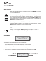
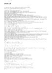
CLEO
MARK 2
USER MANUAL
USER MANUAL
CLEO MARK 2
The information contained within this manual does not include all of the details of design, production or
variations of the equipment. Nor does it cover every possible situation that may arise during installation,
operation or maintenance. If you need particular assistance beyond the scope of this manual please contact our
technical staff.
Magnetic Field - Caution
CAUTION
RISK OF ELECTRIC SHOCK
DO NOT OPEN
WARNING! RISK OF HAZARDOUS ENERGY!
TO REDUCE RISK OF ELECTRIC SHOCK OR FIRE DO NOT
EXPOSE TO RAIN OR MOISTURE.
NO USER SERVICEABLE PARTS INSIDE.
REFER SERVICING TO QUALIFIED SERVICE PERSONNEL.
UNIT MUST BE EARTHED AND CORRECTLY FUSED.
If an equipment rack is to be used, we would
recommend mounting the amplifiers in the bottom of
the rack and mounting pre-amplifier and other
sensitive equipment such as the Cleo Mk2 at the top of
the rack.
Do not locate sensitive high-gain equipment such as
pre- amplifier or tape decks directly above or below the
amplifiers.
Because amplifiers have a high power density there is
a strong magnetic field which can induce hum into
unshielded devices that are located nearby. The field
is strongest just above and below the unit.
The exclamation mark triangle is used to
alert the user to important operating or
maintenance instructions in the
literature accompanying the product.
The lightning bolt triangle is used to alert
the user to the presence of un-insulated
“dangerous voltage” within the unit that
may constitute a risk of electric shock.
CE Conformity
Features
This equipment has been tested and found to conform
to the requirements of the EMC Directive 89/336/EEC,
the requirements of the Low Voltage Directive
73/23/EEC, amended by 93/68/EEC and to the
following standards:
EMC Emission
EN55103-1 (1996)
EMC Immunity EN55103-2 (1996)
Electrical Safety EN60065 (1998)
!
!
!
!
!
!
!
!
2 Input 6 Output configuration
Input on Male XLR, Output on Female XLR
Parametric, Bell or Shelving on any Filter
Dynamic Range of 112dB un-weighted
Digital gain adjustments from -15dB to 15dB
MIDI system Exclusive (sysex) dump capabilities
Pre-loaded with system parameters for Ohm speakers
Attractive styling
Wellington Close • Parkgate • Knutsford
Cheshire • WA16 8XL • England
Tel: +44 (0)1565 654641 • Fax: +44 (0)1565 755641
Email: [email protected] • Website: www.ohm.co.uk
2
CLEO
INTRODUCTION
Congratulations on having purchased an OHM CLEO Mark 2
Please read this manual and familiarize yourself with the operation of your OHM CLEO Mark 2 before
you attempt to power up the unit. For your own safety we recommend you take the time to read all
the warnings and precautions on the page opposite and study the connection details to ensure
correct usage and avoid any misuse which may invalidate your warranty.
Record the serial number, found on the back of the unit, in the spaces designated on the warranty
card, and in the space provided below. Refer to the model and serial numbers whenever you call
your dealer for information or service on this product.
Model
Serial Number
Unpacking
Carefully open the shipping carton and check for any noticeable damage.
Every OHM CLEO Mark 2 has been rigorously tested and inspected before being carefully packaged,
prior to shipping. If any damage has occurred to the packaging or the unit during transit, please
notify the delivery company as soon as possible. Only the consignee can file a claim against the
carrier for shipping damage. Be sure to save the carton and all packing materials for the carriers
inspection.
We recommend that you retain the original carton and packing materials for use should you transport
or ship the unit in future.
Precautions
! Retain this manual for future reference.
! Do not stand the unit vertically on its rear.
! Always check that the correctly rated power is supplied to your unit.
! Avoid direct contact of your CLEO with water or other liquids.
! Do not operate this unit while standing in liquid
!
When cleaning the unit wipe with a soft, dry cloth.
If more heavy duty cleaning is required,
disconnect from the mains and use a damp cloth, ensuring that the unit is completely dry before
reconnecting to the mains.
!
Do not use solvents or chemicals on the exterior of the unit as the may cause the surface to
discolour or peel.
This unit is only intended for qualified personnel to operate and install. Do not attempt to repair or
service yourself. Please refer to qualified technical service department. The user must have sufficient
electrical contact to earth. Electrostatic charges may effect the operation of the CLEO.
3
FEATURES
Active crossover filters with up to 48dB/Octave slopes to divide the audio spectrum into separate
passbands for each transducer. Up to six outputs can be derived from either of the two inputs or a
sum of both.
Up to thirty eight bands of parametric or shelving equalization for smoothing system frequency
response over the entire bandwidth.
60 storage locations for user programs.
Up to 630 ms signal path (in 21µs steps) on inputs for delay towers and clusters and outputs for
transducer alignment.
Output Limiters, with adjustable thresholds and automatic attack and release settings based on
crossover frequency,
protects speakers from overloads damage whilst retaining full musical
dynamics.
Front panel controls for channel muting, programming and level information.
Security Lock Out modes for protecting and hiding program settings.
Delay units representable in milliseconds, metres, feet and frames per second.
Polarity reversal on each output.
Digital gain adjustment from -15dB to 15dB.
MIDI system exclusive (sysex) Dump capabilities to save and transfer programs between units and to
archive settings.
Wide mails range : 90~250V 50/60Hz.
4
CLEO
FRONT PANEL
LED Input Barographs
The Input Barographs respond to -30dB input and also indicate
CLIP
LIMIT
3dB
6dB
12dB
24dB
30dB
These show the input level: -30dB, -24dB, -12dB,
digital clipping.
-6dB, -3dB, LIMIT, CLIP. In
addition, the CLIP lights function both as analog input clip indicators and to show if
there is clipping in the digital signal path. If both A&B CLIP LEDs flash but the LED
directly below the CLIP does not, this would indicate that the DSP is clipping and not
the analog input circuitry. This situation would most likely be caused by excessive
digital gain or EQ in one or more outputs.
A
LED Output Barographs
CLIP
LIMIT
3dB
6dB
12dB
24dB
30dB
The Output Barographs represent signal level relative to the limiter threshold
The Jog Dial
To the right of the display screen there is a continuous JOG DIAL that, when turned,
changes the values in the value area of the screen. If this control is pushed in it will
step through the input and output modes. If held down and tuned it will enable fast
switching through the available modes.
PREV, NEXT,
and
These buttons enable the user to scroll through the various screens and to both
select a parameter to adjust(PREV/NEXT) and to fine adjust the value of the
currently selected parameter (
and
=). Where the parameter is non-numeric
these keys scroll through a list of options.
5
FRONT PANEL
SAVE/RECALL
Used to save edited programs to a new memory location and to RECALL save setups
from the internal memories.
To select a reconfigured program press the RECALL button on the front panel. From
new the unit does not contain any preset programs but if the unit has been used
before it may contain user preprogrammed setups. Use the PREV / NEXT buttons
located on the left side of the LCD screen to choose the correct program. Press the
RECALL again to enable the program.
The save key is also used as an ENTER button to confirm certain operations.
Pressing the SAVE key when in recall mode will exit the operation and pressing
RECALL in a save operation will achieve the same results.
MUTE
Press any of the front panel MUTE keys to toggle the channel in and out of
mute. The button will light red when the output is muted.
LCD Display
DIGITAL SPEAKER
MANAGEMENT
This display can generally be addressed in four working areas:
1. The top left area shows the current operational mode (Input or Output).
2. The bottom left area displays the currently selected parameter associated with the above mode.
3. The bottom right area indicates the value associated with this parameter.
4. The top right area only displays information relating to the current state of the CLEO.
Mode
Parameter
6
IN SUM A+B *
Delay 2.14ms
Information
Value
CLEO
OPERATION
1.
PROGRAMS
1.1 Program Saving
A program can be stored in any one of the 60 available memory locations. Pressing SAVE/ENTER
displays the Save screen with the last used program on the screen. Pressing either PREV/ENTER
or turning the JOG DIAL enables the selection of the required memory for saving your new program.
SAVE
1 MINISTRY
1.2 Program Naming
The program can be given a name using alphanumerical characters of up to 8 digits in length. To input a
new name, press the
to move the cursor into the name area of the screen. The screen will display the
current name of the program that is being edited (after a short time), and the cursor will locate under the
first character to be modified. Characters can be changed using the PREV / NEXT buttons or the JOG
DIAL and the next character along can be selected using the
Button. Use the
button to go back to
change or correct previously set characters.
Pressing SAVE / ENTER a second time will save the new name if the program location is not locked.
1.3 Program Lock
User programs can be locked to prevent accidentally overwriting the memory. The store will fail if the
lock button character is displayed when SAVE / ENTER is pressed. The ‘Program Locked’ message will
appear on the screen for a few seconds, when the message disappears the lock can be turned off with
either the next button or by turning the JOG DIAL anticlockwise. This will now successfully save the new
name.
PROGRAM LOCKED!
1 PLASA
After pressing the SAVE / ENTER button the CLEO asks whether the program should be saved ‘Locked’
or ‘Unlocked’. Turning the JOG DIAL will select between the two options, select your preference and
press SAVE / ENTER.
STORE UNLOCKED ?
LOCKED
STORE UNLOCKED ?
UNLOCKED
1.4 Program Recall
Pressing RECALL will enter the recall mode with the last used program on the screen. Use the PREV /
ENTER buttons or the JOG DIAL to select a program to recall. Only programs that have already been
stored will be available to choose from. There will always be at least one default program in existence in
the unit’s memory.
7
OPERATION
RECALL
1 UNUSED
Pressing RECALL a second time will recall the program.
1.5 Delete Program
Under Utilities mode, press either
or turn the JOG DIAL clockwise, enter into the Delete
Program Mode:
UTILITIES
DELETE PROG
ENTER TO DELETE
1 MONITORS
NO
Choose the program to be deleted using the
Press enter to delete the program.
and
buttons.
Pressing the PREV/NEXT buttons at any time will exit the Delete Program mode.
Note: locked programs have to be unlocked to be deleted, this applies to Program Lock and
OEM/Owner locks.
2.
CONFIGURATION
2.1 Configuration
Configuration is the basis of the unit and saved as part of the program information, along with the
Stereo Link setting associated with the mode chosen here. Changing this mode reconfigures the
overall routing and linking of the unit. The operation has to be confirmed, as routing, linking, delay
linking and crossover band name will all be changed. The unit will also mute outputs to ensure that
appropriate bandwidth settings can be checked before continuing. The output parameters can now
be changed including the routing, delay linking and band names as required.
UTILITIES
CONFIG
MONO
A number of particular system configurations are possible using that CLEO. Select the
configuration that is closest to your needs and change the parameters as necessary. The
configuration setting is saved as part of the program data when a setup is stored to a user memory.
To select the desired configuration use the
and
buttons or the JOG DIAL This will display a
screen similar to the one shown below that asks to change the setup to the displayed configuration.
CHANGE TO 3 WAY ?
ENTER TO CONFIRM
8
CLEO
OPERATION
Press SAVE/ENTER to reconfigure the CLEO to the desired set up.
Pressing any other keys will cancel the operation and return you to the previous configuration.
2.2
Mono Mode
Switching to Mono configuration forces all Outputs to be routed from input A.
Crossover frequencies are set to OUT, i.e. Full range operation.
Delay linking defaults to off.
Stereo linking is unavailable.
Band names will be changed to ‘Band 1’ through ‘Band 6’
CHANGE TO MONO ?
ENTER TO CONFIRM
2.3
2 Channel * 3 Way Mode
UTILITIES
CONFIG 2CH 3WAY
Output 1,3 & 5 are routed from Input A.
Output 2,4 & 6 are routed from Input B.
All delay linking defaults to off.
Stereo Link will be switched on.
Band names will be set to 1&4 ’low’, 2&5 ’mid’, 3&6 ‘high’ for Outputs 1~6 respectively.
NOTE: LOW AND HIGH FREQUENCIES ARE SET TO DEFAULT VALUES.
If the CLEO is used for a stereo 2 way only system, Outputs 3-6 would be used with Low (3&4) and
High (5&6). This allows Subwoofers to be added later on Output 1&2 without the need to rewire
existing systems.
Output 1
L
Output 2
Stereo Link
L
Delay
Link
Delay
Link
Output 3
M
Delay
Link
H
Output 5
Output 4
Stereo Link
Stereo Link
M
H
Delay
Link
Output 6
9
OPERATION
2.4
LCR 2 Way Mode
When using a derived centre cluster feed such as in LCR (Left, Centre, Right) installation, the
configuration can be changed to a 3 channel 2 way configuration, where the centre is a sum of A &
Outputs 1 & 4 are routed from Input A.
Outputs 3 & 6 are routed from Input B.
Outputs 2 & 5 will be routed from Input sum A+B.
All delay linking defaults will be switched off.
Stereo Link will be switched on.
Band Names will be set to ‘Low’ & ‘High’.
Stereo Link
Output 1
Delay
Link
L
Output 2
Delay
Link
L
Output 3
Delay
Link
L
H
H
H
Output 4
Output 5
Output 6
Stereo Link
3.
STEREO LINK
3.1 Stereo Link
This parameter adjusts the stereo linking of various input and output parameters and works in
conjunction with the configuration setting. This parameter is also stored as part of the program data.
SETUP
STEREO LINK
ON
In 2 channel 3 way mode, Output pairs 1&2, 3&4, 5&6 are linked.
In LCR 2 way mode outputs 1, 2 & 3 are typically low and 4,5 & 6 are high.
3.2
Step and Offset
There are two different relationships between linked parameters: Step and Offset.
A step parameter has discrete selections such as Filter type, High pass slope, Polarity, etc. When
channels are linked and a step parameter is changed, e.g High pass slope type, both channels values
will be forced to be the same.
10
CLEO
OPERATION
Offset parameters don’t have discrete selections, instead they have a range of numerical values
such as gain, frequency or delay. These parameters can have offsets between them when the
channels are linked. If any linked parameter reaches the value limit, none of the linked parameters
will be able to move further in that direction.
Table 1 Linked parameter relationships
2 Channel 3 Way
Parameter
Linking Type
Input Delay
Offset
A-B
A-B
Step
A-B
A-B
Input EQ Frequency
Offset
A-B
A-B
Input EQ +/-
Offset
A-B
A-B
Output Name
Offset
1-2, 3-4, 5-6
1-3, 4-6
Output Source
Offset
A(1, 3&5) /B(2, 4&6)
A(1&4) / B(2&6) / A+B(3&5)
Output Gain
Offset
1-2, 3-4, 5-6
1-3, 4-6
Output Limit
Offset
1-2, 3-4, 5-6
1-3, 4-6
Output Delay
Offset
1-3, 3-5, 2-4, 4-6
1-4, 2-5, 3-6
Output Delay Link
Offset
1-3, 3-5, 2-4, 4-6
1-4, 2-5, 3-6
Output Polarity
Step
1-2, 3-4, 5-6
1-3, 4-6
Output Lo Shape
Step
1-2, 3-4, 5-6
1-3, 4-6
Offset
1-2, 3-4, 5-6
1-3, 4-6
Step
1-2, 3-4, 5-6
1-3, 4-6
Offset
1-2, 3-4, 5-6
1-3, 4-6
Step
1-2, 3-4, 5-6
1-3, 4-6
Output EQ Frequency
Offset
1-2, 3-4, 5-6
1-3, 4-6
Output EQ +/-
Offset
1-2, 3-4, 5-6
1-3, 4-6
Output EQ Width
Offset
1-2, 3-4, 5-6
1-3, 4-6
Input EQ Type
Output Lo Frequency
Output Hi Shape
Output Hi Frequency
Output EQ Type
LCR 2 Way
11
OPERATION
4.
CROSSOVER MODE
SETUP
XOVER MODE BOTH
This Utility allows the crossover slopes of the associated bands to be linked together for ease of
setting. For example, when in 'Both' mode changing the frequency of the Hi slope of an output
channel set up as say 'low' band will also change the frequency of the Lo slope in the adjacent 'Mid'
band output channel. The bands do not necessarily need to actually crossover at the same frequency
as an offset can be maintained between them.
Both
Edge
L
L
M
L
M
L
M
M
Edge mode keeps all the crossover slopes separately adjustable. This mode is useful in initial system
set up to tune a driver/cabinet's individual response.
SETUP
*
XOVER MODE BOTH
5
DELAY UNITS
Pressing the PREV/NEXT button, you will be able to scroll to the Delay Units screen.
SETUP
DELAY UNITS
ms
Delay Units can be changed for the specific application to display in:
Milliseconds (ms)
Frames per second (24, 25 & 40 fps)
Feet/inches (ft ‘ins’)
Metres (m)
Use the
and
button or JOG DIAL to select the preferred measurement units.
Returning to the delay parameter will then allow the delay value to be viewed and adjusted in the
selected units.
12
CLEO
OPERATION
6.
SECURITY LOCK OUTS
6.1
Security Settings
There are three levels of security for the unit, Lock Out, OEM Lock and Owner Lock. These are
used to protect the parameters or programs from being inadvertently changed or tampered with by
unqualified or unauthorized users.
6.2
Lock Out
This is the most basic security. With Lock Out on, no parameters can be adjusted(except Lock Out
and Display Contrast), mutes and trims are inactive and no programs can be stored or recalled.
Unless you know how to unlock the unit in the Utilities page, the unit will stay safe from accidental
change.
SETUP
LOCK OUT
6.3
OFF
OEM Lock
OEM Lock allows the user to lock any or all of the parameters in a single program from being seen or
adjusted. These locks are stored within the program.
SETUP
OEM LOCK
Pressing
OFF
from the Utilities screen, shown above, displays the password screen. The default
password is ‘ABCD’. Enter a new alphabetic password by using the
and
buttons to move the
cursor and the down buttons or JOG DIAL to change the letters.
OEM PASSWORD
********
Pressing SAVE/ENTER briefly displays the following message and then enters the Lock All mode.
LOCK SETUP
OEM
ENTER WHEN DONE
6.4 Lock All
This screen allows all the parameters to be locked immediately, they can be selectively unlocked at a
later date. To lock all parameters use
or turn the JOG DIAL clockwise to display ‘YES’. If some
locks have already been set and you want to unlock them all, set this option to ‘YES’ then back to
‘NO’.
To skip this option, press SAVE/ENTER.
LOCK SETUP
LOCK ALL ?
OEM
NO
13
OPERATION
6.5 Lock Set Up Mode
A further press of either the PREV/NEXT buttons enters the Lock Set up mode.
Once in the Lock Setup Mode it is possible to navigate around the input and output screens as
normal but with these important differences:
Parameter values can no longer be changed.
The SAVE and RECALL screen are not accessible.
Only the Config and Stereo Link Utilities are lockable.
The unit is always unlinked.
If a parameter is unlocked the parameter name and value is displayed as usual. Pressing
or turning
the JOG DIAL clockwise changes the value display to a check mark, as shown below, to indicate that
this parameter is now locked. Select the particular parameters that are to be locked from view and
change their values to check marks. Conversely, if Lock All was selected then select and change the
parameters state to unlocked, e.g. No check mark as required.
IN B
DELAY *
OEM
EQs. will not display in lock setup mode if they are unassigned, i.e. not given any cut/boost value.
Attempting to save into a new EQ will display the following screen:
NO MORE EQS OWN
LOCK UNUSED ?
This allows the programmer to prevent a user from assigning further EQs. Alternatively the ability to
add further EQs. Can be left on.
If the CLEO is powered down while in Lock setup mode, the unit will be returned to the locked state
when it is turned back on, with the current password still valid.
IMPORTANT: write down your password and keep it in a safe place. There is no way around
this security mechanism without the password.
6.6
Confirming the Lock Selection
When all the desired parameters are locked, confirm the lock setup process with the
SAVE/ENTER button, (as indicated when first entering the mode). The unit now returns to
the password screen with the current password displayed. This password can be changed if
required by using the
and
button to move the cursor and the PREV/NEXT or the JOG
DIAL to change the letters.
NEW PASSWORD ? *
ABCD
14
CLEO
OPERATION
Pressing SAVE/ENTER saves the password and returns the display to the Utilities menu.
The unit will now not display locked parameters. If all parameters for a particular input or output
channel have been locked the selection button for that channel will no longer display any associated
screens as there are no parameters available to adjust.
Unlocked parameters display as normal and can still be edited although the associated program
cannot be stored back into it’s original locked location and must be saved to a new user memory. In
order to free up the memory location for further use, the locked program would have to be deleted,
using the Delete Prog facility in the Utilities.
The screen below shows a program that has both been OEM locked, (indicated by the diamond
symbol) and that unlocked parameters have been edited, (indicated by the asterisk). The program
edited symbol ‘*’ is not displayed in the Lock setup mode.
1 UNUSED
*
To return to the Lock setup mode to revise the selection of locked parameters or to turn the locks off
altogether, select the Utilities mode and locate the lock screen. Press the
button or turn the JOG
DIAL anti-clockwise to display the password screen. Enter the password and press SAVE/ENTER,
lock will now be switched off.
6.7 Owner Lock
This second level of security operates in exactly the same way as OEM lock except that where ‘OEM’
was displayed there is now the word ‘OWN’ and the diamond icon is replaced by a padlock, see below
left. It is possible to use both these modes in conjunction to give particular access to some
parameters and not others. In this case both the padlock and the diamond symbols are displayed in a
single icon, see below right. The default password for the Owner lock is ‘MINI’.
1 UNUSED
7.
The
1 UNUSED
CONTRAST
and
parameter button or rotary encoder increase/decrease the display contrast and viewing
angle of the LCD. A graphical indication of the parameter changing is displayed by a rotating line
symbol.
SETUP
CONTRAST
15
OPERATION
8
DELETE PROGRAM
To delete a program, press either
or turn theJOG DIAL clockwise.
SETUP
DELETE PROG
Choose the program to be deleted using the
Press ENTER to delete the program.
and
NO
button, or the JOG DIAL.
Pressing the PREV/NEXT button at any time will leave the Delete Program mode.
ENTER TO DELETE
1 MONITORS
Notes:
Locked programs have to be unlocked before they can be deleted, this applies to Program Lock and
OEM/Owner Locks.
9.
MIDI OPERATION
9.1 MIDI Channel Number(1-16)
MIDI is used to transmit and receive program changes and to transmit system exclusive dump data
between units. Use the
and
buttons or rotary encoder to adjust the channel number from 1 to 16.
Both sending and receiving equipment needs to be set to the same MIDI channel to communicate
correctly.
SETUP
MIDI CHANNEL 16
9.2 MIDI Mode (OFF, PROGRAM, MASTER, THRU, PC PORT)
This mode sets the type of information the CLEO transits on it’s MIDI out socket, and is dependent
on the use of the CLEO in the system. The possible selections are:
OFF
No MIDI messages, except systems exclusive dumps, are transmitted.
SETUP
MIDI MODE
OFF
PROGRAM (Prog)
Enables the unit to transmit MIDI program changes.
SETUP
MIDI MODE
16
PROG
CLEO
OPERATION
MASTER
Enables transmission of all control changes to other devices on the same MIDI channel, e.g. To run
two CLEO in parallel for stereo applications.
SETUP
MIDI MODE
MASTER
THRU
Allows the throughput of data received at the MIDI in socket to the MIDI out.
SETUP
MIDI MODE
THRU
PC PORT
This mode allows the RS-232 port on the rear of the CLEO to be used to perform MIDI systems
exclusive dumps and to control other CLEO.
SETUP
MIDI MODE
9.3
PCPORT
MIDI Systems Exclusive Dump
This Utility is used to transfer Program information between CLEO units of the same model as well
as to any MIDI Sysex (System Exclusive) capable sequencer or computer. Attach a MIDI cable
SETUP
MIDI DUMP
Pressing the
*
NO
button on the sending unit will display the prompt screen as seen below.
MIDI DUMP ?
ENTER TO CONFIRM
A MIDI sysex message is now sent out that prompts the receiving unit that an incoming MIDI
dump will occur. A receiving CLEO should display a message to allow an incoming dump.
If you do not want the receiving unit to have it’s memories overwritten then press the
button on
the receiving unit to change the ‘Allow Dump?’ Message to ‘NO’. The receiving unit will return to
normal operation and ignore any incoming program information.
Pressing PREV/NEXT at any time will return the sending unit to the Utilities mode.
Pressing SAVE/ENTER on the sending unit performs the dump.
17
OPERATION
The sending unit should now display the following message.
MIDI DUMP
PREPARING...
If communication is successful then a progress percentage will be shown on the sending unit. When
this reaches 100% the sending unit will return to the MIDI dump default screen and the MIDI
dump is complete.
NOTE: A system dump received by a different model can wipe all the memory information from that
unit. If you have several different models linked together and you wish to perform sysex dumps
between them make sure that all that should not receive the information are either switched off or set
to another MIDI channel.
10.
INPUT
10.1 Input Mode
There are three input sections: input A, input B and input Sum (A+B). Delay and EQ can be added to
inputs A, B and stereo linked A&B but only delay is available directly to the sum A+B.
IN B
DELAY
*
0.007M
10.2 Input Delay
Delay is available from 0-635ms in 21µs increments for input A, input B and input sum A+B. There
cannot be more than 635.417ms delay on any input or output path.
Delay units to represent this value, as milliseconds, feet, or frames per second are set in the Utilities
section.
10.3 input EQ
inputs A, B (and A&B) can have EQ assigned to them. High and Low shelving with 12dB or 6dB/Octave
slopes as well as full parametric bell curves are available. To add EQ to input sum A+B, adjust EQ
parameters on the individual unmixed inputs (A,B) which are then summed into A+B.
IN A & IN B
Eq1
BE11
11
*
Sp12
OUTPUTS
There are six output sections: output1~output6.
The output parameter screens are accessed by pushing the the JOG DIAL
11.1
Stereo Linked Outputs
When the unit is Stereo Linked, combinations of outputs are linked so that when changing
parameters such as EQ or crossover settings, both channels change together.
In 2 channel 3 way configuration, output 1 and 2 parameters, output 3 and 4 parameters and output
5 and 6 parameters are ganged in pairs.
18
CLEO
OPERATION
In LCD 2 way configuration outputs 1,3 and 5 are linked as are 2,4 and 6.
When outputs are linked, the band name is derived from the channel assigned to the lower numbered
output. Similarly, if the linked outputs are offset, the parameter value for the lower numbered output
is displayed. To see the values set for the higher numbered output turn stereo link off.
11.2
Output Name
OUT 1 & 2
NAME
Band1
Band1
The output band name is selected from a pre-programmed list. Use the and button or the JOG
DIAL to scroll through the list. Choose a name that most appropriately describes the usage for each
channel.
Available names:
L Low, L Mid, L High
R Low, R Mid, R High
C Low, C Mid, C High
Subs, Low, Low Mid, Hi Mid, High
Mid+High
1”Horn, 1.5”horn, 2”horn
Bullet
Flat
Unused
Bar, Bstage
Delay
Centre
Mono
Aux
Delay 1-6
10”, 12”, 15”, 18”, 21”, 24”
L Subs, C Subs, R Subs
Source
Choose which input or combination of inputs supplies the output channel.
The options are input A, input B or the sum of inputs A and B - denoted as A+B. When stereo linked in
2 channel 3 way mode, the selection is normally inputs A&B.
OUT 1&2
SRCE IN
Band1 *
A&B
11.3
Gain
Output channel gain is adjustable from -15dB to +15dB in 0.2dB steps. The nominal setting for
outputs is 0dB.
OUT 1&2
GAIN
BULLET
-13.4DB
19
OPERATION
11.4
limiter
Each output channel has a dedicated limiter that can be set to a threshold anywhere between -10dBu
to +20dBu.
OUT 1 & 2
LIMIT
AUX *
-6.2DBU
There are two primary uses for limiters: One is for prevention of amplifier clipping and the second is
to limit the amount of power transmitted to the transducers. In applications where systems are likely
to run at high volume levels for long periods of time, setting the correct limiter threshold is essential
for the protection of speaker drivers.
The value set in this screen is also the output channel meter reference value. If the limiter is adjusted
to say 2.0dBu, then the output meter for the selected channel will represent +2dBu at LIMIT with the
-3, -6, -12 and -20dBu reading relative to that level. I.e. -1dBu, -4dBu, -8dBu and -18dBu.
Note that limiters are usually set slightly below the maximum settings.
Limiter Level Calculations
The method for setting the limiting threshold is given by the following equation:
Limiting Threshold (dBu)= Transducer voltage limit (dBu) - Amplifier Gain (dB).
11.5
Delay
Output Channel Delay is adjustable from 0-365 ms in 21µs. At no time can there be more then 635
ms of delay on any output path. The
and
buttons select delay time values in 21µs steps whilst the
JOG DIAL can be used to select larger delays quickly.
OUT 1 & 2 BAND 3 *
4.958MS
DELAY
Use the
and
buttons or the JOG DIAL to select the preferred measurements units.
Returning to the delay parameter, by pressing the associated output button, recalculates the delay
values for all displays and remembers this setting until it is either changed or stored with a program.
11.6 Delay Linking
OUT 2
C LOW *
DELAY LINK
TO 5
This is used to maintain offsets between various channels. Typical uses include setting individual
transducer delay offsets for optimum performance and then linking them, i.e. Driver alignment. If
either linked channel is changed, the other linked channel(s) will follow and maintain the offset.
20
CLEO
OPERATION
Normally, the transducer delays are set first, then the overall delay for cluster alignment or delay
tower set- up second. The following table shows the linkable channels in each mode.
OUTPUT
Mono
2 Channel 3 Way
3 Channel 2 Way
1
2
3
4
2
3
4
5
3
4
5
6
4
5
6
None
6
None
None
None
None
5
6
None
When using Delay Linking, it is recommended that the adjustment order is:
Driver alignment within cabinets
Cluster alignment within clusters
Delay alignment between clusters. In two channel 3 way and LCR 2 way, the default settings
include Delay Linking as well as Stereo Linking.
11.7
Polarity
Using the
and
buttons or the JOG DIAL the polarity of the output signal can be invested. If the
polarity is changed on a linked output, both outputs will change in the same selection.
OUT 3 & 4
POLARITY
AUX *
NORMAL
11.8 Crossover Shapes and Frequencies
Low edge filter type
The low edge filter can be selected from the Bessel 12, 24dB/Octave or Butterworth 6, 12, 18, 24 or
48dB/Octave or Linkwitz-Riley 12, 24 and 48dB/Octave.
OUT 5 & 6
LO SHAPE
HIGH *
L-R 24
The options are displayed as:
BUT 6,
BUT12,BES12,L-R12,
BUT18
BUT24,BES24,L-R24,
BUT48,L-R48.
Low edge filter frequency
This control adjusts the cut off frequency of the selected Low Frequency (high pass) Crossover. The
range is from 15Hz to 16KHz in approximately 1/6 Octave steps with ‘Out” at the bottom end and ‘Off’
when adjusted beyond 16KHz.
21
OPERATION
OUT 5 & 6
LO FREQ
HIGH *
8.00KHZ
Note: If the Low edge filter frequency is raised beyond 16KHz, the channel output will be
switched off. This is different to muting the output channel in that any signal assigned to
this output will not indicate on the output meters.
High edge filter type
The high edge filter frequency can be selected from Bessel 12, 24dB/Octave or Butterworth 6,
12,18,24 or 48dB/Octave or Linkwitz-Riley 12, 24 or 48dB/Octave.
The options are displayed as:
BUT6
BUT12, BES12, L-R12
OUT 5 & 6
HIGH *
HIGH SHAPE L-R 48
BUT18
BUT24, BES 24, L-R24
BUT48, L-R48.
High edge filter frequency
This control adjusts the cut off frequency of the selected High Frequency Crossover. The range is
from 15Hz to 16KHz in approximately 1/6 Octave steps with ‘Out’ beyond 16KHz.
12
Assignable EQ
OUT 5 & 6
LO SHAPE
HIGH *
L-R 24
Multiple EQ’s can be assigned to individual input and output channels.
If there is no EQ on the currently selected channel (and there are filters available), the PREV button
will step into an unused Bell EQ with 1KHz frequency, 0dB Cut/Boost and width of 0.3. Further EQ’s
can only be assigned to a channel after this EQ is used first by applying some degree of Cut or Boost,
pressing the PREV button then steps into a new EQ.
The EQ Parameters are in the order: EQ type, EQ frequency, EQ Cut/Boost amplitude and then EQ
Width (for Bell type frequencies only).
EQ type
The screen below shows that the first EQ is on outputs 1&3 (labeled as ‘Low’) and that it is assigned in
stereo, denoted by the S, which also indicates that two EQ’s are in use (across the two channels). A
12dB/Octave low shelving type has been chosen and there are currently still 26 spare DSP filters.
OUT 1 & 3
LOW *
EQ1S LO12
SP26
22
CLEO
OPERATION
EQ Frequency
The frequency of the EQ is adjustable from 15Hz to 16Khz in approximately 1/6 Octave steps. The
screen below shows that this is the first EQ on Output2 (labeled as ‘High’). It has a frequency of 1Khz.
If using a Low Shelving filter this would be the 3dB point.
OUT 2
EQ1 FQ4
HIGH *
1KHZ
EQ Cut/Boost
Selectable gain from -15dB to +15dB in 0.5dB steps. Setting an EQ Cut/Boost to 0dB effectively
de-assigns the filter and allows it to be assigned to another channel.
OUT 2
EQ1 + -
HIGH *
6.5DB
EQ Bandwidth
Width is only available for Bell type EQs 0.05 to 3.00 Octaves in 0.05 Octave steps.
OUT 6
EQ1
BAND 6 *
WD2.200 OCT
REAR PANEL
(1)
(2)
(3)
(4)
(5)
(1) POWER SUPPLY IEC MAINS PLUG: 90~250VOLTS, 50/60HZ
(2) RS232 CONNECTOR
(3) MIDI OUT/MIDI IN/MIDI THRU
(4) OUTPUTS: OUTPUT 1~6
(5) INPUTS: INPUT 1~2
23
SPECIFICATIONS
Input Section
Input Impedance
Maximum Input Level
Input Gain
CMRR
Input Connector
10kOhm, electronically balanced
+20dBu
+/-15dB variable in 0.1dB steps
Better than 50dB (30Hz-20kHz)
XLR-3F or equivalent
Output Section
Output Impedance
Maximum Output Level
Output Gain
Output Connector
<50 Ohms, electronically balanced
+20dBu into 600 Ohms or greater
+/-21dB, variable in 0.1dB steps
XLR-3M or equivalent Transformer Balancing optional
Crossover Filters
Slopes
Type
6, 12, 18, 24, or 48dB per octave (Filter type dependant)
Bessel, Butterworth, or Linkwitz-Riley
Delays
Delay Step
Max Delay time
21µs
630ms
EQ
Maximum number of EQ filters
EQ Type
EQ Gain
Q (bandwidth)
EQ freq
Dynamic Slope
General Performance
Frequency Response
Dynamic range
Channel Separation
Distortion (THD)
Input Metering
Output Meter Indication
General
Dimensions
Weight
AC Power
Fuse
As part of our continuous R & D programme,
24
60 (depending on crossover slopes)
Parametric, Bell or shelving on any filter. Nine filters assigned to
Dynamic EQ.
+/-15dB, variable in 0.2dB steps
0.05 to 3 octaves, variable in 0.05 steps
15Hz to 20kHz
2:1 to 20:1 ( dynamic EQ's only )
with filters out
15Hz - 20kHz, +/-0.25dB 15Hz - 40kHz, +/-3dB
>112dB unweighted 22Hz to 22kHz , >117dB on AES/EBU input
>80dB, 30Hz to 20kHz
<0.005%, 20Hz - 20kHz @+10dBu output
-20dB, -12dB, -6dB, -3dB, CLIP relative to Clip point (+20dBu)
SIG (-40dB), -20dB, -12dB, -6dB, -3dB, 0dB, OVER (+6dB)
relative to limiter threshold setting
(481mm x 44mm x 223mm)
3.6kgs, unpacked
90V-250V 50/60Hz
T 1A
reserves the right to change specifications without prior notice.
CLEO
NOTES.
Wellington Close • Parkgate • Knutsford
Cheshire • WA16 8XL • England
Tel: +44 (0)1565 654641 • Fax: +44 (0)1565 755641
Email: [email protected] • Website: www.ohm.co.uk