1
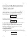
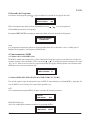
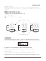
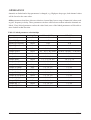
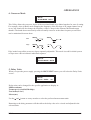
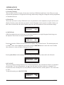
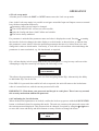
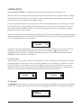
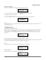
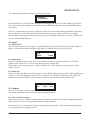
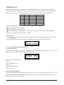
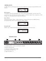
Manual de Usuario / User’s Manual
DSP-26
Antes de utilizar el equipo, lea la sección
“Precauciones de seguridad” de este manual.
Conserve este manual para futuras consultas.
Before operating the device, please read the
“Safety precautions” section of this manual.
Retain this manual for future reference.
DSP-26
DSP-26
Precauciones de Seguridad
Safety Precautions
Procesadores / Processors
Conserve y lea todas estas instrucciones.
Siga todas las advertencias.
El signo de exclamación dentro de un triángulo indica la
existencia de componentes internos cuyo reemplazo puede
afectar a la seguridad.
Keep these instructions.
Heed all warnings. Follow all instructions.
The exclamation point inside an equilateral triangle indicates the
existence of internal components whose substitution may affect
safety.
Aparato de Clase I.
Class I device.
El signo del rayo con la punta de flecha, alerta contra la
presencia de voltajes peligrosos no aislados. Para reducir el
riesgo de choque eléctrico, no retire la cubierta.
The lightning and arrowhead symbol warns about the presence
of uninsulated dangerous voltage. To reduce the risk of electric
shock, do not remove the cover.
El equipo dispone de un conector estándar IEC320-14, con
portafusible, como conector de alimentación.
The device have a standard connector
fuseholder, for mains.
El cableado exterior conectado a estos terminales requiere de su
instalación por una persona instruida o el uso de cables flexibles
ya preparados.
The connected outer wiring to these terminals requires of its
installation by an instructed person and the use of a flexible the
cable already prepared.
Este símbolo indica que el presente producto no puede ser
tratado como residuo doméstico normal, sino que debe
entregarse en el correspondiente punto de recogida de equipos
eléctricos y electrónicos.
This symbol on the product indicates that this product should
not be treated as household waste. Instead it shall be handed
over to the appicable collection point for the recycling of
electrical and electronic equipment.
La posición de encendido está indicada en el interruptor
mediante los correspondientes símbolos normalizados (IEC
60417-1:1998 y IEC 60417-2:1998).
The ON position is indicated in the switch by means of the
corresponding standardized symbols (IEC 60417-1:1998 and
IEC 60417-2:1998).
Si el aparato es conectado permanentemente, la instalación
eléctrica del edificio debe incorporar un interruptor multipolar con
separación de contacto de al menos 3mm en cada polo.
If the apparatus is connected permanently, the electrical system
of the building must incorporate a multipolar switch with a
separation of contact of at least 3mm in each pole.
No exponga este equipo a la lluvia o humedad. No use este
aparato cerca del agua (piscinas y fuentes, por ejemplo). No
exponga el equipo a salpicaduras ni coloque sobre él objetos
que contengan líquidos, tales como vasos y botellas. Equipo IP20.
Do not expose this device to rain or moisture. Do not use this
apparatus near water (for example, swimming pools and
fountains). Do not place any objects containing liquids, such as
bottles or glasses, on the top of the unit. Do not splash liquids
on the unit. IP-20 equipment.
Limpie con un paño seco. No use limpiadores con disolventes.
Clean only with a dry cloth. Do not use any solvent based
No instale el aparato cerca de ninguna fuente de calor como
radiadores, estufas u otros aparatos que produzcan calor. Debe
instalarse siempre sin bloquear la libre circulación de aire.
Do not install near any heat sources such as radiators, heat
registers, stoves or other apparatus that produce heat.
The circulation of air must not be blocked.
Equipo diseñado para funcionar entre 15ºC y 35ºC con una
humedad relativa máxima del 75%.
Working temperature ranges from 15ºC to 35ºC with a relative
humidity of 75%.
Desconecte este aparato durante tormentas eléctricas,
terremotos o cuando no se vaya a emplear durante largos
periodos.
Unplug this apparatus during ligtning storms, earthquakes or
when unused for long periods of time.
Tenga en cuenta que la tensión nominal de alimentación es el
valor indicado en la etiqueta, con un rango ±10% de ese valor
(según IEC 60065:2001). Si debe sustituir el fusible preste
atención al tipo y rango.
Take into account that the nominal AC voltage is the value shown
in the equipment ±10% (according to IEC 60065:2001). If the
fuse needs to be replaced, please pay attention to correct type
and ratings.
Si el cable o enchufe de alimentación está dañado, debe ser
sustituido por un cable o conjunto especial a suministrar por el
fabricante o por su servicio postventa.
If the cable or the mains plug are damaged they must be
replaced. Contact the manufacturer to provide you with the
necessary spare parts.
No existen partes ajustables por el usuario en el interior de este
equipo. Cualquier operación de mantenimiento o reparación
debe ser realizada por personal cualificado. Es necesario el
servicio técnico cuando el aparato se haya dañado de alguna
forma, tal como que haya caído líquido o algún objeto en el
interior del aparato, haya sido expuesto a lluvia o humedad, no
funcione correctamente o haya recibido un golpe.
No user serviceable parts inside. Refer all servicing to qualified
service personnel. Servicing is required when the apparatus has
been damaged in any way, such as power-supply cord or plug is
damaged, liquid has been spilled or objects have fallen into the
apparatus, the apparatus has been exposed to rain or moisture,
does not operate normally or has been dropped.
IEC320-14, with
DECLARACIÓN DE CONFORMIDAD
DECLARATION OF CONFORMITY
D.A.S. Audio, S.A.
C/ Islas Baleares, 24 - 46988 - Pol. Fuente del Jarro - Valencia. España
(Spain).
Declara que DSP-26:
Declares that DSP-26:
Cumple con los objetivos esenciales de las Directivas:
Abide by essential objectives relating Directives:
l
Directiva de Baja Tensión (Low Voltage Directive)
2006/95/CE
l
Directiva de Compatibilidad Electromagnética (EMC)
2004/108/CE
l
Directiva RoHS
2002/95/CE
l
Directiva RAEE (WEEE)
2002/96/CE
Y es conforme a las siguientes Normas Armonizadas Europeas:
In accordance with Harmonized European Norms:
l
EN 60065:2002
l
EN 55103-1:1996 Electromagnetic compatibility.
Product family standard for audio, video, audiovisual and entertainment lighting control apparatus
for professional use. Part 1:Emission.
l
EN 55103-2:1996 Electromagnetic compatibility.
Product family standard for audio, video, audiovisual and entertainment lighting control apparatus
for professional use. Part 2:Immunity.
Audio, video and similar electronic
apparatus. Safety requirements.
CARACTERÍSTICAS
I
0
¡ Filtros activos con pendientes de hasta 48dB/Octava para dividir el espectro del audio en pasabandas
separados para cada transductor. Pueden derivarse hasta seis Salidas de cualquiera de las dos
Entradas o la suma de ambas.
¡ Hasta 38 bandas de ecualización paramétrica o shelving para suavizar la respuesta en frecuencia
del sistema sobre el ancho de banda completo.
¡ 60 memorias de almacenamiento para Programas de usuario.
¡ Hasta 630 ms de retardo de señal por ruta de señal (en pasos de 21 µs) en Entradas y Salidas para
torres retardadas y clusters, así como para el alineamiento de altavoces.
¡ Limitadores de salida con umbrales ajustables y ajustes automáticos de ataque y liberación basados
en la frecuencia del crossover, protección de altavoces frente a daños por sobrecarga mantienendo
toda la dinámica musical.
¡ Controles en el panel frontal de mute, programación e información de nivel por canal.
¡ Modos de Bloqueo de Seguridad para proteger y ocultar los ajustes de programa.
¡ Unidades de Retardo representadas en milisegundos, metros, pies y frames por segundo.
¡ Inversión de Polaridad en cada Salida.
¡ Ajuste digital de ganancia desde -15 a +15dB.
¡ Capacidad de volcado de exclusivo sistema MIDI (sysex) para guardar y transferir programas
entre unidades y para archivar ajustes.
¡ El rango de voltaje está entre: 90~250V 50/60Hz
DSP-26
Manual del usuario/ User´s manual
1
PANEL FONTAL
I
0
Medidores LED de Entrada
Los medidores de Entrada responden a -30dB de señal de entrada y también
indican el clipping digital. Indican el nivel de entrada: -30dB, -24dB, -6dB, -3dB,
LIMIT, CLIP
Además, las luces funcionan tanto como indicadores de clip de entrada analógica
como para indicar si se produce clipping en la ruta de la señal digital. Si los CLIPs
A&B destellan pero el LED que está inmediatamente debajo del CLIP no lo hace,
significa que el DSP está en clipping y no el cicuito analógico de entrada. Esta
situación puede producirse por una excesiva ganancia digital o EQ en una o más
Salidas.
Medidores LED de Salida
Los medidores de Salida representan el nivel de señal relativo al umbral del limitador.
Mando Giratorio
A la derecha de la pantalla hay un mando giratorio contínuo que cuando es accionado
cambia los valores en el área de valores de la pantalla. Si se pulsa este control,
cambiaremos secuencialmente los modos de Entradas y Salidas. Si lo mantenemos
pulsado y lo giramos, conmutará rápidamente a través de los modos disponibles.
PREV, NEXT,
y
Estos botones permiten la navegación a través de las diferentes pantallas y la
selección de un parámetro para ajustar (PREV/NEXT) y la realización de ajustes
precisos del valor del parámetro seleccionado (< y >). Cuando el parámetro no es
numérico estas flechas desplazan la pantalla a través de la lista de opciones.
2
Manual del usuario/ User´s manual
DSP-26
PANEL FRONTAL
RECALL y SAVE/ENTER
Sirven para almacenar Programas editados en una nueva memoria y para recuperar
ajustes guardados desde las memorias internas.
Para seleccionar un Programa preconfigurado, pulse el botón RECALL. El aparato
no contiene ningún preset de Programa de fábrica, pero si la unidad ha sido utilizada
anteriormente puede contener ajustes de usuario preprogramados. Utilice PREV/NEXT
para elegir el Programa correcto. Pulse RECALL otra vez para activar el Programa.
La tecla SAVE se utiliza también como botón de ENTER para confirmar ciertas
operaciones. Pulsando SAVE cuando estamos en modo “recall” saldremos de la
operación y pulsando RECALL en una operación “save” conseguiremos el mismo
resultado.
Mute
Presionar cualquier tecla MUTE del panel frontal para activar o desactivar el mute
de ese canal. El botón se encenderá en rojo cuando la salida esté en mute.
LCD Display
DIGITAL SPEAKER
MANAGEMENT
La pantalla generalmente está dividida en cuatro áreas de trabajo:
1. El área superior izquierda muestra el modo en el que está el DSP-26 ( Input o Output)
2.El área inferior izquierda muestra el parámetro seleccionado actualmente, asociado con el modo
superior.
3.El área inferior derecha indica el valor asociado con este parámetro.
4.El área superior derecha sólo muestra información activa al estado actual del DSP-26.
Modo
Parámetro
DSP-26
IN SUM A+B *
Delay 2.14ms
Información
Valor
Manual del usuario/ User´s manual
3
USO
1.Programas
1.1 Almacenamiento de Programas
Un programa puede ser almacenado en cualquiera de las 60 memorias disponibles. Pulsando
SAVE/ENTER muestra la pantalla Save con el último programa usado. Pulsando cualquier botón
PREV/NEXT o girando la rueda seleccionaremos la memoria para almacenar nuestro nuevo
Programa.
SAVE
1 MINISTRY
1.2 Nombre de Programa
El programa puede nombrarse con caracteres alfanuméricos con una longitud de hasta 8 dígitos.
Para introducir un nuevo nombre pulse “>” para mover el cursor en la zona del nombre de la pantalla.
La pantalla mostrará el nombre actual del Programa que está siendo editado (después de un corto
tiempo), y el cursor se colocará bajo el primer caracter para ser modificado. Los caracteres pueden
cambiarse utilizando PREV/NEXT o girando la rueda y el siguiente caracter puede seleccionarse
usando la tecla >. Use la tecla < para volver a cambiar o corregir caracteres previamente introducidos.
Pulsando SAVE/ENTER una segunda vez efectuará el almacenamiento si la memoria no está bloqueada.
1.3 Bloqueo de Programas
Los programas pueden bloquearse para evitar que la sobre escritura sea fácil. No se podrá almacenar
un Programa si aparece en la pantalla el símbolo de bloqueo cuando pulsamos SAVE/ENTER. El
mensaje 'Program Locked!' Permanecerá en pantalla durante algunos segundos. Después de la
desaparición de este mensaje, el bloqueo puede desactivarse utilizando la tecla NEXT o girando la
rueda en sentido contrario a las agujas del reloj. El almacenamiento se habrá realizado con éxito.
PROGRAM LOCKED!
1 PLASA
Después de la operación de almacenamiento, el DSP-26 preguntará si el programa debe ser guardado
'Locked' (bloqueado) o 'Unlocked' (desbloqueado). Girando la rueda seleccionaremos entre 'Locked'
y 'Unlocked' , seleccione lo deseado y pulse SAVE/ENTER por tercera vez para completar la operación.
STORE UNLOCKED ?
LOCKED
STORE UNLOCKED ?
UNLOCKED
1.4 Recuperación de Programas
Pulsando RECALL entrará en el modo de recuperación con el último Programa usado en pantalla.
Use PREV/NEXT o la rueda giratoria para seleccionar el programa a recuperar. Solo estarán
disponibles los Programas que hayan sido almacenados. Siempre habrá por lo menos un Programa
por defecto en la memoria del aparato.
4
Manual del usuario/ User´s manual
DSP-26
USO
RECALL
1 UNUSED
Pulsando RECALL por segunda vez recuperaremos el programa.
1.5 Borrado de Programas
En el modo Utilities , pulsar
o girar la rueda en el sentido de las agujas del reloj y pulsar Enter en
el modo Delete Program. Esto cambiará la pantalla:
UTILITIES
DELETE PROS
ENTER TO DELETE
1 MONITORS
NO
Elija el programa que quiera borrar usando los botones
Pulsar Enter para borrar el Programa.
Pulsando PREV/ NEXT en cualquier momento saldrá del modo de Borrado de Programas.
Nota: Los Programas bloqueados deben desbloquearse antes de ser borrados. Esto también es válido
para los programas bloqueados OEM/Owner.
2. Configuración
2.1 Configuración
La configuración es el ajuste básico de la unidad y se almacena como parte de la información de
Programa junto con los ajustes de Enlace Estéreo asociados con el modo escogido. Cambiando este
modo reconfiguraremos el enrutamiento general y el enlace de la unidad. La operación debe confirmarse
para cambiar los datos de enrutamiento, enlace, enlace de retardos y nombre de banda del filtro. La
unidad muteará las Salidas para permitir que los ajustes de ancho de banda puedan ser comprobados
antes de continuar. Los parámetros de Salida pueden ser cambiados ahora incluyendo el enrutamiento,
el enlace de retardos y los nombres de las bandas como se desee.
UTILITIES
CONFIG
MONO
Diversas configuraciones de sistema son posibles con el DSP-26. Seleccione la configuración más
próxima a sus necesidades y cambie los parámetros necesarios. Los ajustes de configuración se
guardarán como parte de los datos del Programa cuando se almacena en la memoria del usuario.
Para seleccionar la configuración deseada utilice
y
o la rueda. Mostrará una pantalla similar
a la de la figura, que pregunta para cambiar el ajuste de la configuración mostrada.
CHANGE TO 3 WAY ?
ENTER TO CONFIRM
DSP-26
Manual del usuario/ User´s manual
5
USO
Pulse enter para reconfigurar el DSP-26 para el sistema deseado.
Pulsando cualquier otra tecla cancelará la operación y volverá a la configuración previa.
2.2 Modo Mono
Conmutando a Mono fuerza todas las Salidas a ser enrutadas desde la Entrada A.
Las frecuencias del crossover se ajustan a OUT, Ejemplo: Trabajar a Full range.
Enlace de retardos por defecto desconectado.
El enlace Estéreo no está disponible.
Los nombres de las Bandas cambiarán a 'Band 1' hasta 'Band 6'.
CHANGE TO MONO ?
ENTER TO CONFIRM
2.3 Modo 2 Canales *3 Vías
UTILITIES
CONFIG 2CH 3WAY
Salidas 1,3 y 5 se direccionan desde la Entrada A.
Salidas 2,4 y 6 se direccionan desde la Entrada B.
Todos los Enlaces de retardo desconectados por defecto.
Se activará el Enlace Estéreo.
Los nombres de las bandas (Band Names) cambiarán a 1'low', 2'mid', 3'high', 4'low', 5'mid',
'high' para Salidas 1~6 respectivamente. Las frecuencias de crossover Graves y Agudas se ajustan
a los siguientes valores por defecto:
Si se utiliza el DSP-26 para un sistema estéreo de 2 vías, las salidas 3 a 6 deberían ser usadas como
Graves (3-4) y Agudos (5-6). Esto permite después añadir subgraves en las Salidas 1 y 2 sin recablear
el sistema.
Salida 1
L
Retardo
Enlazado
Retardo
Enlazado
Salida 2
Enlace Estéreo
Salida 3
M
H
Salida 4
Enlace Estéreo
Enlace Estéreo
Salida 5
6
L
M
H
Retardo
Enlazado
Retardo
Enlazado
Salida 6
Manual del usuario/ User´s manual
DSP-26
USO
2.4 Modo LCR 2 vías
Cuando utilizamos un cluster central en una instalación LCR (Left, Center, Right), la configuración
debe cambiarse a 3 canales 2 vías, donde el canal central es la suma de los canales A y B.
Salidas 1 y 4 se direccionan desde la Entrada A.
Salidas 3 y 6 se direccionan desde la Entrada B.
Salidas 2 y 5 se direccionan desde las suma de las Entradas A+B.
Todos los Enlaces de retardo desconectados por defecto.
Se activará el Enlace Estéreo.
Los nombres de las Bandas se ajustarán a 'Low' and' High'.
Enlace Estéreo
Salida 4
Retardo
Enlazado
L
Salida 5
Retardo
Enlazado
Salida 6
L
Retardo
Enlazado
L
H
H
H
Salida 1
Salida 2
Output 3
Enlace Estéreo
3. Enlace Estéreo
3.1 Enlace Estéreo
Este parámetro ajusta el enlace estéreo de varios parámetros de Entrada y Salida. Trabaja conjuntamente con los ajustes de Configuración. Este parámetro también se almacena como parte de los datos
del Programa.
SETUP
STEREO LINK
ON
En el modo 2 canales 3 vías, se enlazan las parejas de Salida 1 y 2, 3 y 4, 5 y 6.
En el modo LCR 2 vías, las Salidas 1, 2 y 3 son normalmente graves y 4, 5 y 6 agudos.
3.2 Step y Offset
Hay dos relaciones diferentes entre parámetros de enlace: Step (Paso) y Offset(Compensación).
Un parámetro Step tiene selecciones como tipo de filtro, pendiente pasa altos, polaridad, etc.
DSP-26
Manual del usuario/ User´s manual
7
USO
Cuando los canales están enlazados y se cambian los parámetros Step (por ejemplo el tipo de pendiente
del pasa altos), los valores de ambos canales serán forzados al mismo valor.
Los parámetros Offset no tienen selecciones, en su lugar disponen de un rango de valores numéricos
como ganancia, frecuencia o retardo. Estos parámetros pueden compensarse entre ellos cuando se
enlazan los canales. Si cualquier parámetro enlazado alcanza el valor límite, ninguno de los parámetros
enlazados será capaz de moverse más alla en esa dirección.
Tabla 1 Relaciones entre parámetros de enlace
Parámetro
Tipo de Enlace
2 Canales 3 Vías
LCR 2 Vías
Offset
A-B
A-B
Tipo de EQ de Entrada
Step
A-B
A-B
Frecuencia EQ Entrada
Offset
A-B
A-B
+/- EQ de Entrada
Offset
A-B
A-B
Nombre de Salida
Offset
1-2, 3-4, 5-6
1-3, 4-6
Fuente de Salida
Offset
Ganancia de Salida
Offset
1-2, 3-4, 5-6
1-3, 4-6
Limitador de Salida
Offset
1-2, 3-4, 5-6
1-3, 4-6
Retardo de Salida
Offset
1-3, 3-5, 2-4, 4-6
1-4, 2-5, 3-6
Enlace de Retardo de Salida
Offset
1-3, 3-5, 2-4, 4-6
1-4, 2-5, 3-6
Polaridad de Salida
Step
1-2, 3-4, 5-6
1-3, 4-6
Curva de Graves de Salida
Step
1-2, 3-4, 5-6
1-3, 4-6
Offset
1-2, 3-4, 5-6
1-3, 4-6
Step
1-2, 3-4, 5-6
1-3, 4-6
Offset
1-2, 3-4, 5-6
1-3, 4-6
Step
1-2, 3-4, 5-6
1-3, 4-6
Frecuencia EQ de Salida
Offset
1-2, 3-4, 5-6
1-3, 4-6
+/- EQ de Salida
Offset
1-2, 3-4, 5-6
1-3, 4-6
Ancho EQ de Salida
Offset
1-2, 3-4, 5-6
1-3, 4-6
yaleD
Retardo de Entrada
Frecuencia de Graves de Salida
Curva de Agudos de Salida
Frecuencia de Agudos de Salida
Tipo de EQ de Salida
8
A(1, 3&5)/ B(2, 4&6) A(1&4) / B(2&6) /A+B(3&5)
Manual del usuario/ User´s manual
DSP-26
USO
4. Modo Crossover
SETUP
XOVER MODE BOTH
Esta utilidad permite enlazar conjuntamente las pendientes del crossover con las bandas asociadas
para un fácil ajuste. Por ejemplo, cuando en el modo “Both” cambiamos la frecuencia del corte
superior en un canal de Salida ajustado como grave “low”, también cambiaremos la frecuencia de
corte inferior en la banda de medios “Mid” contigua del canal de Salida. La frecuencia de corte
entre bandas adyacentes no necesariamente ha de ser la misma.
Both
Edge
L
L
M
L
M
M
L
M
El modo “Edge” mantiene ajustables por separado todas las pendientes del crossover. Este modo es
útil para iniciar los ajustes de respuesta individual de altavoces/recintos.
SETUP
XOVER MODE EDGE
5. Unidades de Retardo
Cuando conectamos la unidad, pulsamos el botón PREV/NEXT y seleccionaremos la pantalla de
Delay Units
SETUP
DELAY UNITS
ms
Para aplicaciones específicas, las unidades de retardo pueden cambiarse para mostrarse en:
Milisegundos(ms)
Frames por segundo(24,25&40fps)
Pies/pulgadas(ft 'ins' )
Metros(ms)
Use las teclas y
o la rueda para seleccionar la unidad de medida preferida.
Volviendo al parámetro de retardo nos permitirá visualizar el valor del retardo y ajustarlo en la
unidad seleccionada.
DSP-26
Manual del usuario/ User´s manual
9
USO
6. Bloqueo de Seguridad
6.1 Ajustes de Seguridad
El aparato dispone de tres niveles de seguridad, Lock Out, OEM Lock and Owner Lock. Se utilizan
para proteger los parámetros o Programas de cambios accidentales o manipulaciones por usuarios no
autorizados.
6.2 Lock Out
Esta es la seguridad más básica. Cuando activamos el bloqueo “on”, no se pueden ajustar parámetros
(excepto el bloqueo y contraste de la pantalla), los mutes y trims están inactivos y no se pueden
almacenar ni recuperar Programas. A menos de que sepa cómo desbloquear la unidad, esta se mantendrá
segura frente a cambios accidentales.
SETUP
LOCK OUT
OFF
6.3 OEM Lock
El bloqueo OEM permite al usuario bloquear alguno o todos los parámetros en un Programa individual
para ser vistos o ajustados. Estos bloqueos se almacenan con el programa.
SETUP
OEM LOCK
OFF
Pulsando
aparecerá la pantalla de password mostrada abajo. La contraseña por defecto es "OEM".
Introduzca una nueva contraseña alfabética usando las teclas
y
para mover el cursor y los
botones PREV/NEXT o la rueda giratoria para cambiar las letras.
OEM PASSWORD
********
Pulsando Save/Enter se mostrará brevemente el siguiente mensaje y entonces entrará en el modo
“Lock All”.
LOCK SETUP
OEM
ENTER WHEN DONE
6.4 Lock All
Esta pantalla permite bloquear todos los parámetros inmediatamente, los cuales puede desbloquear
selectivamente más tarde. Para bloquear todos (ALL) los parámetros, use la tecla
o gire la rueda
hasta que muestre “Yes”. Si hay algunos bloqueos ajustados previamente y desea desbloquearlos
todos, ponga la opción en “Yes” y después en “No”.
Para omitir esta opción pulse SAVE/ENTER.
LOCK SETUP
LOCK ALL ?
10
OEM
NO
Manual del usuario/ User´s manual
DSP-26
USO
6.5 Modo de ajuste de Bloqueo
Con una nueva pulsación de los botones PREV o NEXT entrará en el modo de ajuste de Bloqueo..
Una vez en el modo “Lock setup” es posible navegar por todas las pantallas de Input y Output con
normalidad, pero con estas importantes diferencias:
Los valores de los parámetros no pueden ser cambiados.
Las pantallas SAVE y RECALL no son accesibles.
Sólo las funciones Config y Stereo Link son bloqueables.
La unidad siempre está no enlazada (unlinked).
Si un parámetro está bloqueado, normalmente se muestra el nombre y valor. Pulsando o girando
la rueda en el sentido de las agujas del reloj cambiaremos el valor de la pantalla a una marca de
comprobación, como se ve abajo, que indica que ahora el parámetro esta bloqueado. Seleccione
parámetros concretos que deban ser bloqueados y cambie sus valores para marcarlos con el símbolo
descrito. Inversamente, si se seleccionó “Lock All” entonces seleccione y cambie el estado de los
parámetros para desbloquearlos, eliminando la marca de comprobación en los deseados.
IN B
DELAY
OEM
Las ecualizaciones no se mostrarán en pantalla en el modo ajuste de bloqueo si no están asignadas.
Por ejemplo no entrando ningún valor de realce/atenuación. Cualquier intento de avanzar a una nueva
ecualización mostrará la siguiente pantalla:
NO MORE EQS OWN
LOCK UNUSED ?
Esto permite al programador evitar que el usuario asigne ecualizaciones adicionales. Alternativamente, se
puede dejar activada la posibilidad de añadir nuevas ecualizaciones.
Si se apaga el DSP-26 mientras está en modo ajustes de bloqueo, la unidad volverá al estado de
bloqueo que estaba cuando se apagó, con la contraseña actual todavía válida.
IMPORTANTE: Escriba su contraseña y guárdela en lugar seguro. Ya no hay manera de
acceder al mecanismo de seguridad sin la contraseña.
6.6 Confirmando la selección de bloqueo
Cuando todos los parámetros estén bloqueados, confirme el proceso de ajuste de bloqueo con el botón
SAVE/ENTER (tal como se indicaba cuando se entró por primera vez en este modo). La unidad volverá
a la pantalla de contraseña con la contraseña actual en la pantalla. Si desea cambiar esta contraseña, utilice las
teclas
y
para mover el cursor y las teclas PREV/NEXT (o la rueda) para cambiar las letras.
NEW PASSWORD ? *
ABCD
DSP-26
Manual del usuario/ User´s manual
11
USO
Pulsando SAVE/ENTER guardará la contraseña y volverá al menu de utilidades.
Ahora el DSP-26 no mostrará ningún parámetro bloqueado. Si todos los parámetros para una Entrada y Salida
en particular han sido bloqueados, el botón de selección para este canal no mostrará ninguna de las pantallas
asociadas como si no hubiera parámetros disponibles para ajustar.
Los parámetros no bloqueados se mostrarán normalmente y continuarán pudiendo ser editados aunque el
programa asociado no pueda ser almacenado en su ubicación original bloqueada, debiendo ser guardado
en una nueva memoria de usuario.Para mantener libre la posición de memoria para un uso posterior, el
Programa bloqueado debería ser borrado, utilizando la función “Delete Prog” del menú.
La pantalla inferior muestra un Programa que tiene bloqueo OEM, (indicado por el símbolo de rombo), y
parámetros desbloqueados que han sido editados, (indicado por el asterisco). En el modo de ajuste de bloqueo
no se muestra el símbolo '*' de Programa editado.
C-MARK DS226
1 UNUSED
*
1 UNUSED
*
Para volver al modo de ajuste de bloqueo para revisar la selección de parámetros bloqueados, o para desbloquearlos completamente, seleccione el modo “Utilities” y localice la pantalla de bloqueo. Pulse la tecla o gire
la rueda en sentido contrario a las agujas del reloj para mostrar la pantalla de contraseña. Introduzca la contraseña
y pulse SAVE/ENTER, el bloqueo se desactivará.
6.7 Owner Lock
Este segundo nivel de seguridad funciona exactamente de la misma forma que el bloqueo OEM excepto que
donde antes aparecía la palabra “OEM” aparece la “Own” y el símbolo de rombo es reemplazado por un candado
(ver abajo izquierda). Es posible utilizar ambos modos conjuntamente para permitir un acceso a unos parámetros
en concreto y a otros no. En este caso se mostrarán ambos símbolos, el candado y el rombo en un único icono
(ver abajo a la derecha). La contraseña por defecto para el bloqueo Owner es “SOMA”.
¡
1 UNUSED
*
1 UNUSED
*
7. Contraste
Las teclas de parámetros
y
o la rueda giratoria aumentan o disminuyen el contraste y el ángulo de
visión de la pantalla LCD. La indicación gráfica de este parámetro se indica mediante un símbolo de línea
que gira sobre si misma.
SETUP
CONTRAST
12
Manual del usuario/ User´s manual
DSP-26
USO
8. Borrado de Programa
Para borrar un Programa, pulse
o gire la rueda en el sentido de las agujas del reloj.
SETUP
DELETE PROG
NO
Elija el Programa que quiera borrar utilizando las teclas
Pulsar Enter para borrar el Programa.
y
o la rueda giratoria.
Pulsando PREV/NEXT en cualquier momento saldrá del modo borrado de Programa.
ENTER TO DELETE
1 MONITORS
Nota:
Los programas bloqueados deben ser desbloqueados antes de ser borrados, esto es válido para el
Bloqueo de Programa y los bloqueos OEM/Owner.
9. Funcionamiento MIDI
9.1 Número de Canal MIDI (1-16)
El MIDI se utiliza para transmitir y recibir cambios de Programa y para enviar datos de volcado del
sistema exclusivo entre unidades. Utilice las teclas
y
o la rueda para ajustar el número de canal
del 1 al 16. Tanto el envío como la recepción de datos del equipo deben ajustarse en el mismo canal
MIDI para una correcta comunicación.
SETUP
MIDI CHANNEL 16
9.2 Modo MIDI (OFF, PROGRAM, MASTER, THRU, PC PORT)
Este modo ajusta el tipo de información que el DSP-26 transmitirá por la salida MIDI, y depende del
uso de DSP-26 en el sistema. Las selecciones posibles son:
OFF
No se transmiten mensajes MIDI, excepto volcados del sistema exclusivo.
SETUP
MIDI MODE
OFF
PROGRAMA(Prog)
Activa la unidad para transmitir cambios de programa MIDI.
SETUP
MIDI MODE
DSP-26
PROG
Manual del usuario/ User´s manual
13
USO
MASTER
Activa la transmisión de todos los cambios de control para otros dispositivos en el mismo canal
MIDI, por ejemplo, para ejecutar dos DSP-26 en paralelo en aplicaciones estéreo.
SETUP
MIDI MODE
MASTER
THRU
Permitie el paso de datos recibidos en la entrada MIDI hacia la salida MIDI.
SETUP
MIDI MODE
THRU
PCPORT
Este modo permite utilizar el puerto RS-232 situado en la trasera del DSP-26 para realizar volcados
MIDI del sistema exclusivo y para controlar otros DSP-26.
SETUP
MIDI MODE
PCPORT
9.3 Volcado MIDI del Sistema Exclusivo
Esta utilidad se utiliza para transferir información de programas entre unidades DSP-26, así como
cualquier Sysex MIDI ( sistema exclusivo) a un secuenciador u ordenador. Conectar un cable MIDI
desde la salida MIDI de la unidad que envía a la entrada MIDI de la unidad que recibe.
SETUP
MIDI DUMP
Pulsando la tecla
*
NO
de la unidad que envía, se mostrará la pantalla inferior:
MIDI DUMP ?
ENTER TO CONFIRM
Un mensaje sysex MIDI será enviado tan pronto la unida receptora detecte un volcado MIDI entrante.
El DSP-26 receptor mostrará en pantalla un mensaje preguntando si permite el volcado entrante.
Si no desea que a la unidad receptora se le sobreescriban las memorias, pulse la tecla en la unidad
receptora para cambiar el mensaje "Allow Dump ?" a "No". La unidad receptora volverá a su
funcionamiento normal e ignorará la información del Programa entrante.
Pulsando PREV/NEXT en cualquier momento devolverá la unidad que envía al modo Utilities.
Pulsando SAVE/ENTER en la unidad que envía, realizará el volcado.
14
Manual del usuario/ User´s manual
DSP-26
USO
La unidad que envía mostrará ahora la siguiente pantalla:
MIDI DUMP
PREPARING...
Si la comunicación se realiza con éxito, se mostrará en la pantalla un porcentaje progresivo en la
unidad que envía. Cuando se alcance el 100% la unidad que envía volverá a la pantalla inicial de
MIDI dump y el volcado MIDI estará completo.
NOTA: Un volcado de sistema recibido desde un modelo diferente al DSP-26 puede eliminar toda la
información de la memoria de esa unidad.
10. Entrada
10.1 Modo Entrada
Hay tres secciones de entrada: Entrada A, Entrada B y Suma de Entradas (A+B). Se puede añadir
Retardo y Ecualización a las Entradas A, B y al enlace estéreo A&B, pero sólo el retardo está disponible
directamente para la Suma A+B.
IN B
DELAY
*
0.007M
10.2 Retardo de entrada
El retardo está disponible desde 0-635ms en incrementos de 21 µs para la entrada A, Entrada B y
Entrada A+B. No pueden ajustarse más de 635.417 ms de retardo en cualquier entrada para la ruta
de salida.
Las unidades de valor de Retardo pueden ser milisegundos, pies o frames por segundo y se ajustan
en la sección de Utilidades.
10.3 Ecualización de Entrada
Las entradas A, B (y A& B)pueden tener asignada una EQ. Están disponibles ecualizaciones shelving
de graves y agudos con pendientes de 12dB o 6dB/Octava y curvas de campana totalmente paramétricas.
Para añadir una EQ a la Suma de Entradas A+B, ajuste los parámetros de EQ individualmente (A,B)
sin mezclar, los cuales serán sumados en la entrada A+B.
IN A & IN B
Eq1
BE11
*
Sp12
11. Salidas
Hay seis secciones de salidas: salida1 a salida6
Pulsando el botón se accede a la pantalla de los parámetros de Salida.
11.1 Salidas Estéreo Enlazadas
Cuando la unidad está Enlazada en Estéreo, las combinaciones de Salida están enlazadas para que
cuando se cambien los parámetros como EQ o ajustes del Crossover, ambos canales cambien
conjuntamente.
En una configuración de 2 canales y 3 vías, Los parámetros de las salidas 1 y 2, de las salidas 3 y 4
y de las salidas 5 y 6 están agrupados en pares.
DSP-26
Manual del usuario/ User´s manual
15
USO
En una configuración LCR de 2 vías, se agrupan las salidas 1,3 y 5 y las salidas 2, 4 y 6.
Cuando las Salidas están enlazadas, el nombre de la banda se deriva del canal asignado con el número
más bajo de Salida. Igualmente, si las Salidas enlazadas están compensadas, se muestra el valor del
parámetro de la Salida con el número más bajo. Para ver los valores ajustados a las salidas con el
número más alto, desactive el Enlace Estéreo.
11.2 Nombre de Salida
OUT 1 & 2
NAME
Band1
Band1
El nombre de la banda de salida es seleccionable desde una lista preprogramada. Use las teclas
y
gire la rueda para desplazarse a través de la lista. Elija un nombre que describa más
adecuadamente la utilización para cada canal. Los nombres disponibles son:
L Low, L Mid, L High
R Low, R Mid, R High
C Low, C Mid, C High
Subs, Low, Low Mid, Mid, Hi Mid, High
Mid+High
1"Horn,1.5"Horn,2"Horn
Bullet
Flat
Unused
Bar, Bstage
Delay
Center
Mono
Aux
Delay 1-6
10", 12", 15", 18", 21", 24"
L Subs, C Subs, R Subs
Fuente
Elija qué Entrada o combinación de Entradas suministraran el canal de Salida.
Las opciones son: Input A, Input B o la suma de las entradas A y B (indicada como Input A+B).
Cuando estamos en modo 2 canales 3 vías enlazado estereo, normalmente la selección es Inputs A&B.
OUT 1&2
SRCE IN
Band1 *
A&B
11.3 Ganancia
La ganancia del canal de salida es ajustable desde -15dB a +15dB en pasos de 0.2dB. El ajuste nominal
para las Salidas es de 0dB.
OUT 1&2
GAIN
16
BULLET
-13.4DB
Manual del usuario/ User´s manual
DSP-26
USO
11.4 Limitador
Cada salida tiene un limitador dedicado que puede ajustarse en un umbral cualquiera entre -10 y +20dBu.
OUT 1 & 2
LIMIT
AUX *
-6.2DBU
Hay dos usos primarios para los limitadores: Uno es la prevención del clipping del amplificador y
el segundo es para limitar la potencia entregada a los altavoces. En aplicaciones donde es
probable que los sistemas deban funcionar a elevados niveles de volumen durante largos periodos de
tiempo es importante ajustar el correcto umbral del limitador para proteger los altavoces.
El valor ajustado en esta pantalla es también el valor de referencia del medidor del canal de Salida.
Si el limitador está ajustado a 2.0dBu, el medidor de la Salida de este canal seleccionado representará
+2dBu como LIMIT con las lecturas -3,-6,-12 y -20 dB relativas a este nivel. Por ejemplo -1dBu, -4dBu,
-8dBu y -18dBu.
Observe que habitualmente los limitadores se ajustan ligeramente por debajo del ajuste máximo.
Cálculos para el Nivel del Limitador
El método para ajustar el umbral del limitador viene dado por la siguiente ecuación:
Umbral del limitador(dBu)= Límite del voltaje del altavoz (dBu) -Ganancia del amplificador(dB)
11.5 Retardo
El retardo del canal de Salida es ajustable desde 0-365 ms en pasos de 21µs. No puede haber más de
635ms de retardo desde cualquier Entrada a la ruta de Salida. Las teclas
y seleccionan los valores
de retardo en pasos de 21µs y con la rueda giratoria para seleccionar los retardos largos de forma rápida.
OUT 1 & 2 BAND 3 *
DELAY
4.958MS
Usar las teclas
y
o la rueda giratoria para seleccionar la unidad de medida deseada.
Al pulsar el botón de salida asociada, volveremos a la pantalla de parámetros de retardo con los valores
de retardo recalculados para todas las pantallas y recordará este ajuste hasta que sea nuevamente
cambiado o almacenado con un Programa.
11.6 Enlace de Retardos
OUT 2
C LOW *
DELAY LINK
TO 5
Se utiliza para mantener la misma compensación entre varios canales. Un uso habitual es ajustar el
delay de una vía en un canal y después enlazar con el otro canal (quedan igualados los delays).
DSP-26
Manual del usuario/ User´s manual
17
USO
Normalmente, se ajusta primero el retardo de los altavoces y después cualquier retardo total para el
alineamiento de clusters o torres retardadas.
OUTPUT
Mono
2 Channel 3 Way
3 Channel 2 Way
1
2
3
4
2
3
4
5
3
4
5
6
4
5
6
None
5
6
None
None
6
None
None
None
Cuando se usan retardos enlazados, es recomendable que el orden de ajuste sea:
Alineación de los altavoces en la caja acústica.
Alineación de las cajas acústicas dentro de los clusters.
Alineación del retardo entre clusters. En 2 canales 3 vías y LCR 2 vías, los ajustes por defecto
incluyen retardos enlazados y enlaces estéreo.
11.6 Polaridad
Utilizando las teclas y
o la rueda giratoria podremos invertir la polaridad de la señal de salida.
Si cambiamos la polaridad en una Salida enlazada, ambas Salidas cambiarán a la misma selección.
OUT 3 & 4
POLARITY
AUX *
NORMAL
11.7 Pendientes y Frecuencias de Crossover
Tipo de Filtro del corte inferior (pasa altos)
El tipo de filtro para el corte inferior (pasa altos) puede ser seleccionado entre Bessel 12, 24dB/Octava
o Butterworth 6, 12, 18, 24 o 48 dB/Octava o Linkwitz-Riley 12, 24 y 48dB/Octava.
OUT 5 & 6
LO SHAPE
HIGH *
L-R 24
Las opciones se muestran así:
BUT 6,
BUT12,BES12,L-R12,
BUT18,
BUT24,BES24,L-R24,
BUT48,L-R48.
Frecuencia del corte inferior
Este control ajusta la frecuencia del corte inferior (pasa altos) seleccionado. El margen va desde
15Hz a 16kHz en pasos aproximados de 1/6 Octava con 'Out' en el final inferior y 'Off' cuando
ajustamos más allá de los 16kHz.
18
Manual del usuario/ User´s manual
DSP-26
USO
OUT 5 & 6
LO FREQ
HIGH *
8.00KHZ
Nota: Si el corte inferior (pasa alto) es ajustado por encima de los 16kHz, la salida del canal se
apagará. Esto es diferente de mutear el canal de Salida, ya que cualquier señal asignada a esta
salida no se mostrará en los medidores de Salida.
Tipo de filtro del corte superior (pasa bajos)
El tipo de filtro para el corte superior (pasa bajos) puede ser seleccionado entre Bessel 12, 24dB/Octava
o Butterworh 6,12,18,24 o 48dB/Octava o Linkwitz-Riley 12,24 and 48dB/Octava.
OUT 5 & 6
HIGH *
LO SHAPE
HIGH
SHAPE L-R
L-R24
48
Las opciones aparecen como:
BUT 6, BUT 12, BES 12, L-R 12, BUT 18, BUT24, BES24, L-R 24, BUT48, L-R 48.
Frecuencia del corte superior (pasa bajos)
Este control ajusta la frecuencia de corte superior (pasa bajos) seleccionado. El margen va desde
15Hz a 16kHz en pasos aproximados de 1/6 Octava con el 'Out' más allá de los 16kHz.
OUT 5 & 6
LO FREQ
HI
SHAPE
FLAT*
HIGH *
L-R
OUT
24
12.EQ Asignable
Son asignables múltiples ecualizaciones a canales individuales de Entrada y Salida.
Si no hay EQ en el canal seleccionado actualmente( y hay filtros disponibles), el botón PREV
activará una ecualización nueva tipo Bell con una frecuencia de 1kHz, 0dB de realce/atenuación y un
ancho de 0.3. Se pueden asignar ecualizaciones posteriores a un canal después de que esta ecualización
sea utilizada primero, aplicando algún grado de realce o atenuación, pulsando el botón PREV pasamos
a una nueva EQ.
Los parámetros de EQ están en el siguiente orden: Tipo de EQ, Frecuencia de EQ, Realce/atenuación
de EQ y ancho de EQ (sólo para filtros Bell).
Tipo de EQ
En la pantalla de abajo se muestra que esta es la primera ecualización en las Salidas 1 & 3 ( etiquetadas
como 'Low') y que está asignada en estéreo (indicado por “S”) lo cual indica que se están utilizando
dos Eqs (a través de los canales).
OUT 1
5&3
6
LO SHAPE
EQ1
LO12
DSP-26
LOW
HIGH* *
L-R
SP2624
Manual del usuario/ User´s manual
19
USO
Se ha elegido una pendiente del corte inferior de 12dB/ Octava y filtro tipo Shelving, y quedan 26
filtros DSP sin usar.
OUT 2
EQ1 FQ4
HIGH *
14KHZ
Frecuencia de EQ
La frecuencia del ecualizador es ajustable desde 15Hz a 16kHz en pasos aproximados de 1/6 Octava.
La pantalla inferior muestra que esta es la primera EQ en la Salida 2 ( etiquetada como 'High'). Tiene
una frecuencia de 1kHz. Si utilizamos un filtro Shelving en el corte inferior debería estar en el punto
de los 3dB.
Realce/Atenuación de EQ
Ganancia seleccionable entre -15dB to +15dB en pasos de 0.5dB. Ajustando un realce/atenuación de
0dB desasignamos efectivamente el filtro, permitiendo ser asignado a otro canal.
OUT 2
EQ1 + -
HIGH *
6.5DB
Ancho de EQ
El ancho está sólo disponible para ecualizaciones tipo Bell. Eqs de 0.05a 3.00 Octavas en pasos de
0.05 Octavas.
OUT 6
EQ1
BAND 6 *
WD2.200 OCT
PANEL TRASERO
1
3
2
4
+
+
5
+
+
+
+
+
+
+
(1) CONECTOR DE CORRIENTE: 90~250VOLTS, 50/60HZ
(2) CONNECTOR RS232
(3) MIDI OUT/MIDI IN/MIDI THRU
(4) SALIDAS: SALIDA 1~6
(5) ENTRADAS: ENTRADA 1~2
20
Manual del usuario/ User´s manual
DSP-26
FEATURES
I
0
¡Active crossover filters with up to 48dB/Octave slops to divide the audio spectrum into separate
passbands for each transducer. Up to six Output can be derived from either of the two inputs or a
sum of both.
¡ Up to thirty eight bands of parametric or shelving equalization for smoothing system frequency
response over the entire bandwidth.
¡ 60 storage locations for user Programs .
¡ Up to 630 ms signal delay per signal path ( in 21 s steps) on Inputs and Outputs for delay towers
and clusters as well as transducer alignment.
¡ Output limiters, with adjustable thresholds and automatic attack and release settings based on
crossover frequency, protect speakers from overload damage whilst retaining full musical dynamics.
¡ Front panel controls for channel muting, programming and level information.
¡ Security Lock Out modes for protecting and hiding Program setting.
¡ Delay units representable in milliseconds, meters, feet, and frames per second.
¡ Polarity reversal on each Output.
¡ Digital gain adjustment from -15 to 15dB.
¡ MIDI system exclusive ( sysex) dump capabilities to save and transfer programs between units
and to archive settings.
¡ Wide mains switch : 90~250V 50/60Hz
DSP-26
Manual del usuario/ User´s manual
21
FRONT PANEL
I
0
LED Input Barographs
The Input barographs respond to -30dB input and also indicate digital clipping.
These show the input level: -30dB, -24dB, -6dB, -3dB, LIMIT, CLIP.
In addition, the CLIP lights function both as analog input clip indicators and to
show if there is clipping in the digital signal path. If both A & B CLIP LEDs flash
but the LED directly below the CLIP does not, this would indicate that the DSP
is clipping and not the analog input circuitry. This situation would most likely be
caused by excessive digital gain or EQ in one or more Outputs.
LED Output Barographs
The Output barographs represent signal level relative to limiter threshold.
The Rotary Encoder
To the right of the display screen there is a continuous rotary encoder that, when
turned, changes the values in the value area of the screen. If this control is pushed in
it will step through the inputs and outputs modes. If held down and turned it will
enable fast switching through the available modes.
PREV, NEXT,
and
These enables buttons through the various screens and to both select a parameter to
adjust(PREV/NEXT) and to fine adjust the value of the currently selected parameter
(< and > =). Where the parameter is non-numeric these keys scroll through a list of
options.
22
Manual del usuario/ User´s manual
DSP-26
FRONT PANEL
RECALL and SAVE/ENTER
Used to save edited Programs to a new memory location and to recall saved setups
from the internal memories.
To select a reconfigured Program press the RECALL button on the front panel. From
new the manual does not contain any preset Programs but, if the unit has been used
before it may contain user preprogrammed setups. Use the PREV/NEXT buttons
located on the left side of the LCD screen to choose the correct Program. Press
RECALL again to enable the Program.
The save key is also used as an ENTER button to confirm certain operations.
Pressing the SAVE key when in recall mode will exit the operation and pressing
RECALL in a save operation will achieve the same result.
Mute
Press any of the front panel Mute keys to toggle the channel in and out of mute. The
button will light red when the output is muted.
LCD Display
DIGITAL SPEAKER
MANAGEMENT
This display can generally be addressed in four working areas:
1. The top left shows the mode that the DSP-26 is in ( Input or Output)
2.The button left displays the currency the currently selected parameter associated with the above
mode.
3.The button right area indicates the value associated with this parameter.
4.The top right only displays information relating to the current state of the DSP-26.
Mode
Parameter
DSP-26
IN SUM A+B *
Delay 2.14ms
Information
Value
Manual del usuario/ User´s manual
23
OPERATION
1.Programs
1.1 Program Saving
A Program can be stored in any one of the 60 available memory locations. Pressing SAVE/ENTER
displays the Save screen with the last used Program on the screen. Pressing either PREV/NEXT or
turning the rotary encoder enables the selection of the required memory for saving your new Program.
SAVE
1 MINISTRY
1.2 Program Naming
The Program can be given a name using alphanumeric characters up to 8 digits in length. To input a
new name, press the to move the cursor into the name area of the screen. The screen will display
the current name of the Program that is being edited ( after a short period of time), and the cursor will
locate under the first character to be modified. Characters can be changed using either the PREV/
NEXT buttons or the rotary encoder and the next character along can be selected using the button.
Use the button to go back to change or correct previously set characters.
Pressing SAVE/ENTER a second time will perform the saving if the Program location is not locked.
1.3 Program Lock
User Programs can be locked to prevent overwriting of memories too easily. A store will fail if the
lock button character is displayed when SAVE/ENTER is pressed. The 'Program Locked!' message
will stay on the screen for a few seconds. After this Message has disappeared the lock can be turned
off with either the NEXT button by turning the rotary encoder anticlockwise. The saving will now be
successful.
PROGRAM LOCKED!
1 PLASA
After the saving operation the DSP-26 asks whether the Program should be saved 'Locked' or 'Unlocked'.
Turning the rotary encoder will select between 'Locked' and 'Unlocked' , select your preference and
press SAVE/ENTER a third time to complete the operation.
STORE UNLOCKED ?
LOCKED
STORE UNLOCKED ?
UNLOCKED
1.4 Program Recall
Pressing RECALL will enter the recall mode with the last used Program on the screen. Use the PREV/
NEXT buttons or the rotary encoder to select a Program to recall. Only Programs that have already
been stored will be available to choose from. There will always be at least one default Program in
existence in the unit's memory.
24
Manual del usuario/ User´s manual
DSP-26
OPERATION
RECALL
1 UNUSED
Pressing RECALL a second time will recall the program.
1.5 Delete Program
Under Utilities mode, press either
mode, this will change:
or turn the encoder clockwise, enter into the Delete Program
UTILITIES
DELETE PROS
ENTER TO DELETE
1 MONITORS
NO
Choose the Program to be deleted using the
Press enter to delete the Program.
and
buttons.
Pressing the PREV/ NEXT buttons ate any time will exit the Delete Program mode.
Note: Locked Programs have to be unlocked before they can be deleted, this applies to Program lock
and OEM/Owner locks.
2. Configuration
2.1 Configuration
The configuration us the basic of the unit and is saved as ported of the Program information, along
with the Stereo Link setting associated with the mode chosen here. Changing this mode reconfigures
the overall routing and linking of the unit. The operation has to be confirmed as routing, linking,
delay linking and crossover band name date will be changed. The unit will also mute the Outputs to
ensure that appropriate bandwidth settings can be checked before continuing. The Output parameters
can now be changed including the routing, delay linking and band names as required.
UTILITIES
CONFIG
MONO
A number of particular system configurations are possible using DSP-26. Select the configuration that
is closet to your needs and change the parameters as necessary. The configuration setting is saved as
part of the Program data when a setup is stored to a user memory.
To select the desired configuration use the and buttons or rotary encoder. This will display a
screen similar to the one shown below that asks to change the setup to the displayed configuration.
CHANGE TO 3 WAY ?
ENTER TO CONFIRM
DSP-26
Manual del usuario/ User´s manual
25
OPERATION
Press Enter to reconfigure the DSP-26 to the desired set-up.
Pressing any other keys will cancel the operation and return you to the previous configuration.
2.2 Mono mode
Switching to Mono configuration forces all Outputs to be routed from Input A.
Crossover frequencies are set to OUT, i.e. Full range operation.
Delay linking defaults to off.
Stereo Linking is unavailable.
Band Names will be changed to 'Band 1' through 'Band 6'.
CHANGE TO MONO ?
ENTER TO CONFIRM
2.3 2 Channel * 3 way mode
UTILITIES
CONFIG 2CH 3WAY
Output 1,3 and 5 are routed from Input A.
Output 2,4 and 6 are routed from Input B.
All delay linking defaults to off.
Stereo Link will be switched on.
Band Names will be set to 1'low', 2'mid', 3'high', 4'low', 5'mid', 'high' for Outputs 1~6 respectively.
The Low and High crossover frequencies are set to the following default values:
If the DSP-26 is used for a stereo 2 way only system, Outputs 3-6 would be used with Low(3-4) and
High(5-6). This allows subwoofers to be added late on Output 1 and 2 without rewiring existing
systems.
Output 1
L
Delay
Link
Delay
Link
Output 2
Stereo Link
Output 3
M
H
Output 4
Stereo Link
Stereo Link
Output 5
26
L
M
H
Delay
Link
Delay
Link
Output 6
Manual del usuario/ User´s manual
DSP-26
OPERATION
2.4 LCR 2 way mode
When using a derived center cluster feed such as in LCR (Left, Center, Right) installation, the
configuration can be changed to a 3 channel 2 way configuration, where the center channel is a sum
of A and B.
Outputs 1 and 4 are routed from Input A.
Outputs 3 and 6 are routed from Input B.
Outputs 2 and 5 will be routed from Input sum A+B.
All delay linking defaults to off.
Stereo Link will be switched on.
Band Names will be set to 'Low' and' High'.
Stereo Link
Output 4
L
Delay
Link
Output 5
Delay
Link
Output 6
L
Delay
Link
L
H
H
H
Output 1
Output 2
Output 3
Stereo Link
3. Stereo Link
3.1 Stereo Link
This parameter adjusts the stereo linking of various Input and Outputs Parameters and works in
conjunction with the Configuration setting. This parameter is also stored as part of the Program data.
SETUP
STEREO LINK
ON
In 2 channel 3 way mode, Output pairs 1 and 2, 3 and 4, 5 and 6 are linked.
In LCR 2 way mode Outputs 1, 2 and 3 are typically low and 4, 5 and 6 are high.
3.2 Step and Offset
There are two different relationships between linked parameters: Step and Offset.
A step parameter has discrete selections such as filter type, high pass slope, polarity, etc. When
DSP-26
Manual del usuario/ User´s manual
27
OPERATION
channels are linked and a Step parameters is changed, e.g. High pass slope type, both channel values
will be forced to the same value.
Offset parameters don't have discrete selections, instead they have a range of numerical values such
as gain, frequency or delay. These parameters can have offsets between them when the channels are
linked. If any linked parameter reaches the value limit, none of the linked parameters will be able to
move further in that direction.
Table 1 Linked parameter relationships
Parameter
Input Delay
Linking Type
Offset
2 Channel 3 Way
A-B
LCR 2 Way
A-B
Step
A-B
A-B
Input EQ Frequency
Offset
A-B
A-B
Input EQ +/-
Offset
A-B
A-B
Output Name
Offset
1-2, 3-4, 5-6
1-3, 4-6
Output Source
Offset
A(1, 3&5) / B(2, 4&6)
A(1&4) / B(2&6) / A+B(3&5)
Output Gain
Offset
1-2, 3-4, 5-6
1-3, 4-6
Output Limit
Offset
1-2, 3-4, 5-6
1-3, 4-6
Output Delay
Offset
1-3, 3-5, 2-4, 4-6
1-4, 2-5, 3-6
Output Delay Link
Offset
1-3, 3-5, 2-4, 4-6
1-4, 2-5, 3-6
Output Polarity
Step
1-2, 3-4, 5-6
1-3, 4-6
Output Lo Shape
Step
1-2, 3-4, 5-6
1-3, 4-6
Offset
1-2, 3-4, 5-6
1-3, 4-6
Step
1-2, 3-4, 5-6
1-3, 4-6
Offset
1-2, 3-4, 5-6
1-3, 4-6
Step
1-2, 3-4, 5-6
1-3, 4-6
Output EQ Frequency
Offset
1-2, 3-4, 5-6
1-3, 4-6
Output EQ +/-
Offset
1-2, 3-4, 5-6
1-3, 4-6
Output EQ Width
Offset
1-2, 3-4, 5-6
1-3, 4-6
Input EQ Type
Output Lo Frequency
Output Hi Shape
Output Hi Frequency
Output EQ Type
28
Manual del usuario/ User´s manual
DSP-26
OPERATION
4. Crossover Mode
SETUP
XOVER MODE BOTH
This Utility allows the crossover slopes of the associated bands to be linked together for ease of setting.
For example, when in 'Both' mode changing the frequency of the Hi slope of an output channel set up
as say 'low' band will also change the frequency of the Lo slope in the adjacent 'Mid' band output
channel. The bands do not necessarily need to actually crossover at the same frequency as an offset
can be maintained between them.
Both
Edge
L
L
M
L
M
M
L
M
Edge' mode keeps all the crossover slopes separately adjustable. This mode is useful in initial system
set up to tune a driver/cabinet's individual response.
SETUP
*
XOVER MODE BOTH
5. Delay Units
When you open the power supply, pressing the PREV/NEXT button, you will select the Delay Units
screen .
SETUP
DELAY UNITS
ms
Delay units can be changed for the specific application to display in:
Milliseconds(ms)
Frames per second(24,25&40fps)
Feet/inches(ft 'ins' )
Meters(ms)
Use the
and
button or rotary encoder to select the preferred measurement units.
Returning to the delay parameter will then allow the delay value to be viewed and adjusted in the
selected units.
DSP-26
Manual del usuario/ User´s manual
29
OPERATION
6. Security Lock Outs
6.1 Security Settings
There are three levels of security for the unit, Lock Out, OEM Lock and Owner Lock. These are used
to protect the parameters or Programs from being inadvertently changed or tampered with by unqualified
or unauthorized users.
6.2 Lock Out
This is the most basic security. With lock out on, no parameters can be adjusted (except Lock Out and
display Contrast), mutes and trims are inactive and no Programs can be stored or recalled. Unless you
know how to unlock the unit in the Utilities page, the unit will remain safe from accidental change.
SETUP
LOCK OUT
OFF
6.3 OEM Lock
OEM Lock allows the user to lock any or all of the parameters in a single Program from being seen
or adjusted. These locks are stored with the Program.
SETUP
OEM LOCK
OFF
Pressing from the Utilities screen shown below displays the password screen. The default password
is "OEM". Enter a new alphabetic password by using the and buttons to move the cursor and the
down buttons or rotary encoder to change the letters.
OEM PASSWORD
********
Pressing Save/Enter briefly displays the following message and then enters the Lock All mode.
LOCK SETUP
OEM
ENTER WHEN DONE
6.4 Lock All
This screen allows all the parameters to be locked immediately, they can then be selective ly unlocked
at a later date. To Lock All parameters, use or turn the rotary encoder clockwise to display "Yes" .
If some locks have already been set and you want to unlock them all, set this option to "Yes" then back
to "NO".
To skip this option, press SAVE/ENTER.
LOCK SETUP
LOCK ALL ?
30
OEM
NO
Manual del usuario/ User´s manual
DSP-26
OPERATION
6.5 Lock set up mode
A further press of either the PREV or NEXT buttons enters the Lock set up mode.
Once in the Lock setup mode it is possible to navigate around the Input and Output screens as normal
but with these important differences:
Parameter values can no longer be changed.
The SAVE and RECALL screens are not accessible.
Only the Config and Stereo Link Utilities are lockable.
The unit is always unlinked.
If a parameter is unlocked the parameter name and value is displayed as usual. Pressing or turning
the encoder clockwise changes the value display to a check mark, as shown below, to indicate that
this parameter is now locked. Select the particular parameters that are to be locked from view and
change their values to check marks. Conversely, is Lock All was selected then select and change the
parameters is state to unlocked, e.g. No check mark, as required.
IN B
DELAY
OEM
EQ s will not display in lock set up mode if they are unassigned, i.e. not given any cut/boost value.
Attempting to step into a new EQ will display the following screen:
NO MORE EQS OWN
LOCK UNUSED ?
This allows the programmer to prevent a user from assigning further EQs. Alternatively the ability
to add further EQ s can be left on.
If the DSP-26 is powered down while in Lock set up mode, the unit will return to the locked state
when it is turned back on, with the current password still valid.
IMPORTANT : Write down your password and keep it in a safe place. There is no way around
this security mechanism without the password.
6.6 Confirming the Lock Selection
When all the desired parameters are locked, confirm the lock set up process with the SAVE/ENTER
button, as indicated when first entering this mode). The unit now returns to the password screen with
the current password displayed. This password can be changed if required by using the and button
to move the cursor and the up and down buttons or rotary encoder to change the letters.
NEW PASSWORD ? *
ABCD
DSP-26
Manual del usuario/ User´s manual
31
OPERATION
Pressing SAVE/ENTER save the password and returns the display to the Utilities menu.
The unit will now not display and locked parameters. If all parameters for a particular Input or Output
channel have been locked the selection button for that channel will no longer display any associated
screens as there are no parameters available to adjust.
Unlocked parameters display as normal and can still be edited although the associated Program cannot
be stored back into its original locked location and must be saved to a new user memory. In order to
free up the memory location for further use the locked Program would have to be deleted, using the
Delete Prog facility in the Utilities.
The screen below shows a Program that has both been OEM locked, (indicated by the diamond symbol),
and that unlocked parameters have been edited,(indicated by the asterisk). The Program edited symbol
'*' is not displayed in the Lock setup mode.
C-MARK DSP-26
1 UNUSED
*
1 UNUSED
*
To return to the Lock setup mode to revise the selection of locked parameters or to turn the locks off
altogether, select the Utilities mode and locate the lock screen. Press the button or turn the
rotary encoder anti-clockwise to display the password screen. Enter the password and press SAVE/
ENTER, the lock will now be switched off.
6.7 Owner Lock
This second level of security operates in exactly the same way as OEM lock except that where 'OEM'
was displayed there is now the word 'Own' and the diamond icon is replaced by a padlock, see above
left. It is possible to use both these modes in conjunction in order to give particular access to some
parameters and not others. In this case both the padlock and the diamond symbols are displayed in a
single icon, see above right. The default password for the Owner lock is 'SOMA'.
1 UNUSED
*
1 UNUSED
*
7. Contrast
The and parameter button or rotary control increase/decrease the display contrast and viewing angle
of the LCD. A graphical indication of the parameter changing is displayed by a rotating line symbol.
SETUP
CONTRAST
32
Manual del usuario/ User´s manual
DSP-26
OPERATION
8. Delete Program
To delete a Program, press either or turn the encoder clockwise.
SETUP
DELETE PROG
NO
Choose the program to be deleted using the and button, or rotary control.
Press Enter to delete the Program.
Pressing the PREV/NEXT button at any time will leave the Delete Program mode.
ENTER TO DELETE
1 MONITORS
Notes:
Locked Programs have to be unlocked before they can be deleted, this applies to Program lock and
the OEM/Owner locks.
9. MIDI Operation
9.1 MIDI Channel Number(1-16)
MIDI is used to transmit and receive Program changes and to transmit system exclusive dump data
between units. Use the and buttons or rotary encoder to adjust the channel number from 1 to 16.
Both sending and receiving equipment needs to be set to the same MIDI channel to communicate
correctly.
SETUP
MIDI CHANNEL 16
9.2 MIDI Mode(OFF, PROGRAM, MASTER, THRU, PC PORT)
This mode sets the type of information the DSP-26 transmits on its MIDI out socket, and is dependent
on the use of the DSP-26 in the system. The possible selections are:
OFF
No MIDI messages, except systems exclusive dumps, are transmitted.
SETUP
MIDI MODE
OFF
PROGRAM(Prog)
Enables the unit to transmit MIDI program changes.
SETUP
MIDI MODE
DSP-26
PROG
Manual del usuario/ User´s manual
33
OPERATION
MASTER
Enables transmission of all control changes to other devices on the same MIDI channel for example
to run two DSP-26 in parallel for stereo applications.
SETUP
MIDI MODE
MASTER
THRU
Allows the throughput of data received at the MIDI in socket to the MIDI out .
SETUP
MIDI MODE
THRU
PCPORT
This mode allows the RS-232 port on the rear of the DSP-26 to be used to perform MIDI systems
exclusive dumps and to control other DSP-26.
SETUP
MIDI MODE
PCPORT
9.3 MIDI Systems Exclusive Dump
This Utility is used to transfer Program information between DSP-26 units of the same model as well
as to any MIDI Sysex ( systems exclusive)capable sequencer or computer. Attach a MIDI cable from
the MIDI out of the sending unit to the MIDI in of the receiving unit.
SETUP
MIDI DUMP
Pressing the
*
NO
button on the sending unit will display the prompt screen below.
MIDI DUMP ?
ENTER TO CONFIRM
A MIDI sysex message is now sent out that prompts the receiving unit that an incoming MIDI dump
will occur. A receiving DSP-26 unit should display a message asking to allow an incoming dump.
If you do not want the receiving unit to have its memories overwritten then press the button on the
receiving unit to change the "Allow Dump ?" message to "No". The receiving unit will return to normal
operation and ignore any incoming Program information.
Pressing PREV/NEXT at any time will return the sending unit to the Utilities mode.
Pressing SAVE/ENTER on the sending unit performs the dump.
34
Manual del usuario/ User´s manual
DSP-26
OPERATION
The sending unit should now display the following screen.
MIDI DUMP
PREPARING...
If communication is successful then a progress percentage will be shown on the sending unit. When
this reaches 100% the sending unit will return to the MIDI dump default screen and the MIDI dump
is complete.
NOTE: A system dump received by a different model can wipe all the memory information from that
unit. If you have several different models linked together and you wish to perform sysex dumps
between them make sure that all that should not receive the dump information are either switched off
or set to another MIDI channel.
10. Input
10.1 Input Mode
There are three input sections: Input A, Input B and Input Sum(A+B). Delay and EQ can be added to
Inputs A, B and stereo linked A&B but only delay is available directly to the Sum A+B.
IN B
DELAY
*
0.007M
10.2 Input Delay
Delay is available from 0-635ms in 21 us increments for Input A, Input B and Input A+B. There
cannot be more than 635.417 ms of delay on any input to output path.
Delay units to represent this value, as either milliseconds, feet or frames per second are set in the
utilities section.
10.3 Input EQ
Inputs A, B (and A& B)can have EQ assigned to then. High and low shelving with 12dB or 6dB/Octave
slopes as well as full parametric bell curves are available. To add EQ to Input Sum A+B, adjust EQ
parameters on the individual unmixed inputs(A,B)which are then summed into Input A+B.
IN A & IN B
Eq1
BE11
*
Sp12
11. Outputs
There are six output sections: output1~output6
The Output parameter screens are accessed by pushing the knob.
11.1 Stereo Linked Outputs
When the unit is Stereo Linked, combinations of Outputs are linked so that when changing parameters
such as EQ or Crossover settings, both channels change together.
In 2 channel 3 way configuration, Output 1 and 2 parameters, Output 3 and 4 parameters and Output
5 and 6 parameters are ganged in pairs.
DSP-26
Manual del usuario/ User´s manual
35
OPERATION
In LCD 2 way configuration Outputs 1,3 and 5 are linked as are 2, 4 and 6.
When Outputs are linked, the band name is derived from the channel assigned to the lower numbered
Output. Similarly, if the linked Outputs are offset, the parameter value for the lower numbered Output
is displayed. To see the values set for the higher numbered Output turn Stereo Link off.
11.2 Output Name
OUT 1 & 2
NAME
Band1
Band1
The Output band name is selectable from a pre-programmed list. Use the and button or encoder to
scroll through the list. Choose a name that most appropriately describes the usage for each channel.
Available names:
L Low, L Mid, L High
R Low, R Mid, R High
C Low, C Mid, C High
Subs, Low, Low Mid, Mid, Hi Mid, High
Mid+High
1"Horn,1.5"Horn,2"Horn
Bullet
Flat
Unused
Bar, Bstage
Delay
Center
Mono
Aux
Delay 1-6
10", 12", 15", 18", 21", 24"
L Subs, C Subs, R Subs
Source
Choose which Input or combination of Inputs supplies the Output channel.
The options are: Input A, Input B or the sum of Inputs A and B-denoted as Input A+B. When Stereo
Linked in 2 channel 3 way mode, the selection is normally Inputs A&B.
OUT 1&2
SRCE IN
Band1 *
A&B
11.3 Gain
Output channel gain is adjustable from -15dB to +15dB in 0.2dB steps. The nominal setting for
Outputs is 0dB.
OUT 1&2
GAIN
36
BULLET
-13.4DB
Manual del usuario/ User´s manual
DSP-26
OPERATION
11.4 Limiter
Each Output channel has a dedicated limiter that can be set to a threshold any where between -10 to
+20dBu.
OUT 1 & 2
LIMIT
AUX *
-6.2DBU
There are two primary uses for limiters: One is for prevention of amplifier clipping and the second
is to limit the amount of power transmitted to the transducers. In applications where systems are
likely to be run at high volume levels for long periods of time, setting the correct limiter threshold is
important for the protection of the speaker drivers.
The value set in this screen is also the Output channel meter reference value. If the Limiter is adjusted
to say 2.0dBu, then the Output meter for the selected channel will represent +2dBu at LIMIT with
the -3,-6,-12 and -20 dB reading relative to that level. I.e. -1dBu, -4dBu,
-8dBu and -18dBu.
Note that limiters are usually set slightly below the maximum settings.
Limiter Level Calculations
The method for setting the limiting threshold is given by the following equation:
Limiting Threshold(dBu)= Transducer voltage limit (dBu) -Amplifier gain(dB)
11.5 Delay
Output channel Delay is adjustable from 0-365 ms in 21us steps. At no time can there be more than
635ms of delay on any Input to Output path. The and buttons select delay time values in 21 s steps
whilst the rotary can be used to select larger delays quickly.
OUT 1 & 2 BAND 3 *
DELAY
4.958MS
Use the and buttons or rotary encoder to select the preferred measurement units.
Returning to the delay parameter, by pressing the associated Output button, recalculates the delay
values for all displays and remembers this setting until it is either changed again or stored with a
Program.
11.6 Delay Linking
OUT 2
C LOW *
DELAY LINK
TO 5
This is used to maintain offsets between various channels. Typical uses include setting individual
transducer delay offsets for optimum performance and then linking them, i.e. driver alignment. If
DSP-26
Manual del usuario/ User´s manual
37
OPERATION
either linked channel's delay is changed, the other linked channel(s) will follow and maintain the
offset. Normally, the transducer delays are set first, then any overall delay for cluster alignment or
delay tower set-up second. The following table shows the linkable channels in each mode.
OUTPUT
Mono
2 Channel 3 Way
3 Channel 2 Way
1
2
3
4
2
3
4
5
3
4
5
6
4
5
6
None
5
6
None
None
6
None
None
None
When using Delay Linking, it is recommended that the adjustment order is:
Driver alignment within cabinets
Cabinet alignment within clusters
Delay Alignment between clusters. In 2 channel 3 way and LCR 2 way, the default settings
include Delay Linking as well as Stereo Linking.
11.6 Polarity
Using the and buttons or rotary encoder the polarity of the output signal can be invested. If the
polarity is changed on a linked Output, both Outputs will change to the same selection.
OUT 3 & 4
POLARITY
AUX *
NORMAL
11.7 Crossover Shapes and Frequencies
Low edge filter type
The low edge filter type can be selected from Bessel 12,24dB/Octave or Butterworth 6, 12, 18, 24 or
48dB/Octave or Linkwitz-Riley 12,24 and 48dB/Octave.
OUT 5 & 6
LO SHAPE
HIGH *
L-R 24
The options are displayed as:
BUT 6,
BUT12,BES12,L-R12,
BUT18,
BUT24,BES24,L-R24,
BUT48,L-R48.
Low edge filter frequency
This control adjusts the cut off frequency of the selected Low Frequency( high pass) Crossover. The
range is from 15Hz to 16kHz in approximately 1/6 Octave steps with 'Out' at the bottom end and
'Off' when adjusted beyond 16kHz.
38
Manual del usuario/ User´s manual
DSP-26
OPERATION
OUT 5 & 6
LO FREQ
HIGH *
8.00KHZ
Note: If the low edge filter frequency is raised beyond 16kHz, the channel output will be switched
off. This is different to muting the Output channel in that any signal assigned to this output will
not indicate on the Output meters.
High edge filter type
The High edge filter frequency can be selected from Bessel 12, 24dB/Octave or Butterworh 6,12,18,
24 or 48dB/Octave or Linkwitz-Riley 12,24 and 48dB/Octave.
OUT 5 & 6
HIGH *
LO SHAPE
HIGH
SHAPE L-R
L-R24
48
The options are displayed as:
BUT 6, BUT 12, BES 12, L-R 12, BUT 18, BUT24, BES24, L-R 24, BUT48, L-R 48.
High edge filter frequency
This control adjusts the cut off frequency of the selected High Frequency crossover. The range is from
15Hz to 16kHz in approximately 1/6 Octave steps with 'Out' beyond 16kHz.
OUT 5 & 6
LO FREQ
HI
SHAPE
FLAT*
HIGH *
L-R
OUT
24
12.Assignable EQ
Multiple EQs can be assigned to individual Input and Output channels.
If there is no EQ on the currently selected channel( and there are filters available), the PREV button
will step into an unused Bell EQ with 1kHz frequency, 0dB cut/boost and width of 0.3. Further EQs
can only be assigned to a channel after this EQ is used first by applying some degree of cut or boost,
pressing the PREV button then steps into a new EQ.
The EQ parameters are in the order: EQ type, EQ frequency, EQ Cut/Boost amplitude and then EQ
Width ( for Bell type filters only).
EQ type
This screen below shows that is the first EQ on Outputs 1 & 3 ( labeled as 'Low') and that it is assigned
in stereo, denoted by the S, which also indicates that two EQs are in use (across the two channels).
OUT 1
5&3
6
LO SHAPE
EQ1
LO12
DSP-26
LOW
HIGH* *
L-R
SP2624
Manual del usuario/ User´s manual
39
OPERATION
A 12dB/ Octave low shelving type has been chosen and there are currently 26 spare DSP filters still
channels.
OUT 2
EQ1 FQ4
HIGH *
14KHZ
EQ Frequency
The frequency of the EQ is adjustable from 15Hz to 16kHz in approximately 1/6 Octave steps. The
screen below shows that this is the first EQ on Output 2 ( labeled as 'High'). It has a frequency of 1kHz.
If using a Low Shelving filter this would be the 3dB point.
EQ Cut/Boost
Selectable gain from -15dB to +15dB in 0.5dB steps. Setting an EQ cut/boost to 0dB effectively
de-assigns the filter, allows it to be assigned to another channel.
OUT 2
EQ1 + -
HIGH *
6.5DB
EQ Bandwidth
Width is only available for Bell type EQs 0.05 to 3.00 Octaves in 0.05 Octave steps.
OUT 6
EQ1
BAND 6 *
WD2.200 OCT
REAR PANEL
1
3
2
4
+
+
5
+
+
+
+
+
+
+
(1) POWER SUPPLY JACK: 90~250VOLTS, 50/60HZ
(2) RS232 CONNECTOR
(3) MIDI OUT/MIDI IN/MIDI THRU
(4) OUTPUTS: OUTPUT 1~6
(5) INPUTS: INPUT 1~2
40
Manual del usuario/ User´s manual
DSP-26
ESPECIFICACIONES / SPECIFICATIONS
Entrada
Impedancia de entrada
Nivel Máximo de Entrada
Ganancia de Entrada
CMRR
Conector de Entrada
Input Section
Input Impedance
Maximum Input Level
Input Gain
CMRR
Input Connector
10kOhm, electronically balanced
+20dBu
+/-15dB variable in 0.1dB steps
Better than 50dB (30Hz-20kHz)
XLR-3F or equivalent
Salida
Impedancia de Salida
Nivel Máximo de Salida
Ganancia de Salida
Conector de Salida
Output Section
Output Impedance
Maximum Output Level
Output Gain
Output Connector
<50 Ohms, electronically balanced
+20dBu into 600 Ohms or greater
+/-21dB, variable in 0.1dB steps
XLR-3M or equivalent Transformer Balancing optional
Filtros Crossovers
Pendientes
Tipo
Crossover Filters
Slopes
Type
6, 12, 18, 24, or 48dB per octave (Filter type dependant)
Bessel, Butterworth, or Linkwitz-Riley
Retardos
Pasos de retardo
Máximo retardo
Delays
Delay Step
Max Delay time
21us
630ms
EQ
Número máximo de Eqs
Tipos de EQ
EQ
Maximum number of EQ filters
EQ Type
Ganancia de la EQ
Q (ancho de banda)
Frecuencia EQ
Pendiente Dinámica
EQ Gain
Q (bandwidth)
EQ freq
Dynamic Slope
Características Generales
Respuesta de Frecuencia
Rango Dinámico
Separación de Canales
Distorsión (THD)
Medidor de Entrada
Indicador de medida de Salida
General Performance
Frequency Response
Dynamic range
Channel Separation
Distortion (THD)
Input Metering
Output Meter Indication
General
Dimensiones
Peso
Voltaje
Fusible
General
Dimensions
Weight
AC Power
Fuse
DSP-26
60 (depending on crossover slopes)
Parametric, Bell or shelving on any filter. Nine filters assigned to
Dynamic EQ.
+/-15dB, variable in 0.2dB steps
0.05 to 3 octaves, variable in 0.05 steps
15Hz to 20kHz
2:1 to 20:1 ( dynamic EQ's only )
with filters out
15Hz - 20kHz, +/-0.25dB 15Hz - 40kHz, +/-3dB
>112dB unweighted 22Hz to 22kHz , >117dB on AES/EBU input
>80dB, 30Hz to 20kHz
<0.005%, 20Hz - 20kHz @+10dBu output
-20dB, -12dB, -6dB, -3dB, CLIP relative to Clip point (+20dBu)
SIG (-40dB), -20dB, -12dB, -6dB, -3dB, 0dB, OVER (+6dB)
relative to limiter threshold setting
481 x 44 x 223 mm (19 x 3.5 x 8.8 in)
3.6 kg / 8 lbs (unpacked)
90V-250V 50/60Hz
T 1A
Manual del usuario/ User´s manual
41
GARANTÍA
Todos nuestros productos están garantizados por un periodo de 24
meses desde la fecha de compra.
Las garantías sólo serán válidas si son por un defecto de
fabricación y en ningún caso por un uso incorrecto del producto.
Las reparaciones en garantía pueden ser realizadas,
exclusivamente, por el fabricante o el servicio de asistencia técnica
autorizado.
Otros cargos como portes y seguros, son a cargo del comprador
en todos los casos.
Para solicitar reparación en garantía es imprescindible que el
producto no haya sido previamente manipulado e incluir una
fotocopia de la factura de compra.
WARRANTY
All D.A.S. products are warrantied against any manufacturing defect
for a period of 2 years from date of purchase.
The warranty excludes damage from incorrect use of the product.
All warranty repairs must be exclusively undertaken by the factory
or any of its authorised service centers.
To claim a warranty repair, do not open or intend to repair the
product.
Return the damaged unit, at shippers risk and freight prepaid, to
the nearest service center with a copy of the purchase invoice.
D.A.S. AUDIO, S.A.
C/. Islas Baleares, 24
46988 Fuente del Jarro
Valencia, SPAIN
Tel. 96 134 0525
Tel. Intl. +34 96 134 0860
Fax 96 134 0607
Fax Intl. +34 96 134 0607
D.A.S. AUDIO OF AMERICA, INC.
Sunset Palmetto Park
6816 NW 77th Court.
Miami, FL. 33166 - U.S.A.
TOLL FREE: 1-888DAS4USA
Tel. +1 305 436 0521
Fax +1 305 436 0528
UM_DSP26_01
www.dasaudio.com
D.A.S. AUDIO ASIA PTE. LTD.
25 Kaki Bukit Crescent #01-00/02-00
Kaki Bukit Techpark 1
Singapore 416256
Tel. +65 6742 0151
Fax +65 6742 0157