1
User’s
Manual
DXA170
DAQStudio
IM 04L41B01-62EN
5th Edition
User Registration
Thank you for purchasing YOKOGAWA products.
We invite you to register your products in order to receive the most up to date product
information. To register, visit the following URL.
http://www.yokogawa.com/ns/reg/
PRS 108-01E
Thank you for purchasing DAQStudio.
This manual explains the use of DAQStudio. Please read this manual carefully before
use and use DAQStudio correctly.
After reading the manual, keep it safe at a location where it is easily available at the time
of use. It will help you if you should not understand the handling during use.
Adobe Reader 7 or later of Adobe Systems Incorporated is required to display this
manual.
Notes
• The contents of this manual are subject to change without prior notice.
• Every effort has been made in the preparation of this manual to ensure accuracy.
However, if any questions arise or errors are found in this manual, please inform the
nearest Yokogawa sales representative office.
• Copying or reproduction by any means of all or any part of the contents of this manual
without permission is strictly prohibited.
• Transfer or loan of the software to a third party is prohibited.
• Once the software is unpacked, Yokogawa will not guarantee the designed operation
of the software, except when the original floppy disk is found to be physically
defective.
• Yokogawa will not accept any responsibility for damage caused directly or indirectly as
result of use of this software.
• The serial number will not be reissued, therefore, it must be kept in a safe place.
Security Measures
To deal with security threats, we recommend that you take security measures.
• Apply restrictions to PC network connections.
We recommend that you use an isolated network.
• Manage external media properly.
Prevent malware intrusion through external media, unauthorized file operations on
external media, and information leakage due to misplacement.
• Set a strong password and manage it properly.
Use a password that is at least eight characters in length, and include three types of
characters from uppercase letters, lowercase letters, numbers, and symbols.
Change the password regularly.
• Install antivirus software.
This software has been verified to work on a PC running Microsoft Forefront Client
Security Ver. 1.5.1993.0.
Trademarks
Revisions
• All YOKOGAWA product and brand names used in this manual are either trademarks
or registered trademarks of Yokogawa Electric Corporation.
• vigilantplant, SMARTDAC+, Daqstation, and DXAdvanced are registered trademarks
of Yokogawa Electric Corporation.
• Microsoft and Windows are registered trademarks or trademarks of Microsoft
Corporation in the United States and/or other countries.
• Adobe and Acrobat are registered trademarks or trademarks of Adobe Systems
Incorporated.
• Company and product names that appear in this manual are registered trademarks or
trademarks of their respective holders.
• The company and product names used in this manual are not accompanied by the
registered trademark or trademark symbols (® and ™).
1st Edition: January
2nd Edition: April
3rd Edition: March
4th Edition: August
2009
2009
2010
2010
5th Edition: May 2014
5th Edition: May 2014 (YK)
All Rights Reserved, Copyright © 2009 Yokogawa Electric Corporation
IM 04L41B01-62EN
i
Terms and Conditions of the Software License
NOTICE - PLEASE READ CAREFULLY BEFORE USE
Thank you very much for purchasing this medium containing a software program and related documentation provided by Yokogawa Electric Corporation (hereinafter called
“Yokogawa”), and the program contained, embedded, inserted or used in the medium (hereinafter called the “Yokogawa Software Program”).
By installing the Yokogawa Software Program, you acknowledge that you understand and fully agree to the “Terms and Conditions of the Software License” (hereinafter called
“Terms and Conditions”) which is written in the documentation and separately attached. Accordingly, the Terms and Conditions bind you.
The Yokogawa Software Program and its related documentation including ownership of copyright shall remain the exclusive property of Yokogawa or those third parties who
grants Yokogawa the rights.
Yokogawa hereby grants you permission to use the Yokogawa Software Program on the conditions that you agree to the Terms and Conditions before you install it in or onto
a computer.
IF YOU DO NOT AGREE TO THE TERMS AND CONDITIONS, YOU CANNOT INSTALL THIS MEDIUM, AND MUST PROMPTLY RETURN IT TO YOKOGAWA OR ITS
DESIGNATED PARTY.
Terms and Conditions of the Software License
Yokogawa Electric Corporation, a Japanese corporation (hereinafter called “Yokogawa”), grants permission to use this Yokogawa Software Program (hereinafter called the
“Licensed Software”) to you on the conditions that you agrees to the terms and conditions stipulated in Article 1 hereof.
You, as the Licensee (hereinafter called “Licensee”), shall agree to the following terms and conditions on the software license (hereinafter called the “Agreement”) when the
Licensed Software is installed by the Licensee.
Please note that Yokogawa grants the Licensee permission to use the Licensed Software under the terms and conditions herein and in no event shall Yokogawa intend to
sell or transfer the Licensed Software to the Licensee.
Article 1 (Licensed Software under these Terms and Conditions)
1.1 The terms and conditions stipulated herein shall bind any Licensee who purchases the Licensed Software on the condition that the Licensee consents to agree to the
terms and conditions stipulated herein.
1.2 The “Licensed Software” and required number of license herein shall be specified in the following paragraphs (1) and (2) respectively. The Licensed Software means
and includes all applicable programs and documentation, without limitation, all proprietary technology, algorithms, a factor, invariant, process and/or other know-how
contained therein. These terms and conditions shall also govern any additional software to the Licensed Software inclusive of its version-up or revision-up if Yokogawa
provides them to the Licensee.
(1) Licensed Software Name: DAQStudio (Model DXA170)
(2) Number of License: 1
Article 2 (Grant of License)
2.1 Yokogawa grants the Licensee, for the purpose of single use, non-exclusive and non-transferable license of the Licensed Software with the license fee separately agreed
upon by both parties.
2.2 The Licensee is, unless otherwise agreed upon in writing by Yokogawa, not entitled to change, sell, distribute, transfer, or sublicense the Licensed Software.
2.3 The Licensed Software shall not be copied in part or in whole except for keeping one (1) copy for back-up purpose. The Licensee shall secure or supervise the copy of
the Licensed Software by the Licensee itself with great, strict, and due care.
2.4 The Licensed Software remains the exclusive property of Yokogawa and, if any, those of third parties from whom Yokogawa is sublicensed (hereinafter such third party’s
software is called “Third Party Software”, which may include any software program made or coded by affiliates of Yokogawa). In no event shall the Licensee dump,
reverse assemble, reverse compile, or reverse engineer the Licensed Software so that the Licensee may translate the Licensed Software into other programs or change
it into a man-readable form from the source code of the Licensed Software. Unless otherwise separately agreed upon by Yokogawa, Yokogawa shall not provide the
Licensee the source code for the Licensed Software.
2.5 The Licensed Software and its related documentation inclusive of its ownership of copyright shall be the proprietary property of Yokogawa or a third party who grants
Yokogawa the rights. In no event shall the Licensee transfer, lease, sublicense, or assign any rights relating to the Licensed Software.
2.6 Yokogawa may use or add copy protection in or onto the Licensed Software. In no event shall, regardless of the purpose, the Licensee remove or attempt to remove
such copy protection.
2.7 The Licensed Software may include the Third Party Software. In the case that Yokogawa is granted permission to sublicense to third parties by any licensors (sublicensor) of the Third Party Software under different terms and conditions than those stipulated in this Agreement, the Licensee shall observe such terms and conditions
of which Yokogawa notifies the Licensee in writing separately.
2.8 In no event shall the Licensee modify, remove or delete a copyright notice of Yokogawa and its licenser contained in the Licensed Software, including any copy thereof.
Article 3 (Restriction of Specific Use)
3.1 The Licensed Software shall not be intended specifically to be designed, developed, constructed, manufactured, distributed or maintained for the purpose of the following
events:
a) Operation of any aviation, vessel, or support of those operations from the ground;
b) Operation of nuclear products, its facilities and/or radiation apparatus;,
c) Operation of nuclear weapons, chemical weapons and/or biological weapons, or railroad; or
d) Operation of medical instrumentation directly utilized for humankind or the human body.
3.2 Even if the Licensee uses the Licensed Software for the purposes in the preceding Paragraph 3.1, Yokogawa has no liability to or responsibility for any claims or
damages arising out of the use or operations of the Licensed Software, and the Licensee agrees, on its own responsibility, to solve and settle the claims and damages
and to defend, indemnify or hold Yokogawa totally harmless, from or against any liabilities, losses, damages and expenses (including fees for recalling the Products and
reasonable attorney’s fees and court costs), or claims arising out of and related to the above-said claims and damages.
Article 4 (Warranty)
4.1 The Licensee shall agree that the Licensed Software shall be provided to the Licensee on an “as is” basis when delivered. If defect(s), such as damage to the medium of
the Licensed Software, attributable to Yokogawa is found, Yokogawa agrees to replace, free of charge, any Licensed Software on condition that the defective Licensed
Software shall be returned to Yokogawa’s specified authorized service facility within 12 month from the delivery of Yokogawa after opening the Package at the Licensee’s
expense. As the Licensed Software is provided to the Licensee on an “as is” basis when delivered, in no event shall Yokogawa warrant that any information on or in the
Licensed Software, including without limitation, data on computer programs and program listings, be completely accurate, correct, reliable, or the most updated.
4.2 Notwithstanding the preceding Paragraph 4.1, when Third Party Software is included in the Licensed Software, the warranty period and related conditions that apply
shall be those established by the provider of the third party software.
ii
IM 04L41B01-62EN
Terms and Conditions of the Software License
4.3 When Yokogawa decides in its own judgement that it is necessary, Yokogawa may from time to time provide the Licensee with Release Upgrades specified by Yokogawa
(hereinafter called “Release Upgrades”).
4.4 Notwithstanding the preceding Paragraph 4.3, in no event shall Yokogawa provide Updates where the Licensee or any third party conducted renovation or improvement
of the Licensed Software.
4.5 Correction of nonconformity in the manner and for the period of time provided above shall be the Licensee’s sole and exclusive remedy for any failure of Yokogawa to
comply with its obligations and shall constitute fulfillment of all liabilities of Yokogawa and any third party licensing the Third Party Software to Yokogawa (including any
liability for direct, indirect, special, incidental or consequential damages) whether in warranty, contract, tort (including negligence but excluding willful conduct or gross
negligence by Yokogawa) or otherwise with respect to or arising out of the use of the Licensed Software.
4.6 THE FOREGOING WARRANTIES ARE EXCLUSIVE AND IN LIEU OF ALL OTHER WARRANTIES OF QUALITY AND PERFORMANCE, WRITTEN, ORAL, OR
IMPLIED, AND ALL OTHER WARRANTIES INCLUDING ANY IMPLIED WARRANTIES OF MERCHANTABILITY OR FITNESS FOR A PARTICULAR PURPOSE ARE
HEREBY DISCLAIMED BY YOKOGAWA AND ALL THIRD PARTIES LICENSING THIRD PARTY SOFTWARE TO YOKOGAWA.
Article 5 (Infringement)
5.1 If and when any third party should demand injunction, initiate a law suit, or demand compensation for damages against the Licensee under patent right (including utility
model right, design patent, and trade mark), copyright, and any other rights relating to any of the Licensed Software, the Licensee shall promptly notify Yokogawa in
writing to that effect.
5.2 In the case of the preceding Paragraph 5.1, the Licensee shall assign to Yokogawa all of the rights to defend the Licensee and to negotiate with the claiming party.
Furthermore, the Licensee shall provide Yokogawa with necessary information or any other assistance for Yokogawa’s defense and negotiation. If and when such a
claim should be attributable to Yokogawa, subject to the written notice to Yokogawa stated in the preceding Paragraph 5.1, Yokogawa shall defend the Licensee and
negotiate with the claiming party at Yokogawa’s cost and expense and be responsible for the final settlement or judgment granted to the claiming party in the preceding
Paragraph 5.1.
5.3 When any assertion or allegation of the infringement of the third party’s rights defined in Paragraph 5.1 is made, or when at Yokogawa’s judgment there is possibility of
such assertion or allegation, Yokogawa will, at its own discretion, take any of the following countermeasures at Yokogawa’s cost and expense.
a) To acquire the necessary right from a third party which has lawful ownership of the right so that the Licensee will be able to continue to use the Licensed
Software;
b) To replace the Licensed Software with an alternative one which avoids the infringement; or
c) To remodel the Licensed Software so that the Licensed Software can avoid the infringement of such third party’s right.
5.4 If and when Yokogawa fails to take either of the countermeasures as set forth in the preceding subparagraphs of Paragraph 5.3, Yokogawa shall indemnify the Licensee
only by paying back the price amount of the Licensed Software which Yokogawa has received from the Licensee.
THE FOREGOING PARAGRAPHS STATE THE ENTIRE LIABILITY OF YOKOGAWA AND ANY THIRD PARTY LICENSING THIRD PARTY SOFTWARE TO YOKOGAWA
WITH RESPECT TO INFRINGEMENT OF THE INTELLECTUAL PROPERTY RIGHTS INCLUDING BUT NOT LIMITED TO, PATENT AND COPYRIGHT.
Article 6 (Liabilities)
6.1 If and when the Licensee should incur any damage relating to or arising out of the Licensed Software or service that Yokogawa has provided to the Licensee under
the conditions herein due to a reason attributable to Yokogawa, Yokogawa shall take actions in accordance with this Agreement. However, in no event shall Yokogawa
be liable or responsible for any special, incidental, consequential and/or indirect damage, whether in contract, warranty, tort, negligence, strict liability, or otherwise,
including, without limitation, loss of operational profit or revenue, loss of use of the Licensed Software, or any associated products or equipment, cost of capital, loss
or cost of interruption of the Licensee’s business, substitute equipment, facilities or services, downtime costs, delays, and loss of business information, or claims of
customers of Licensee or other third parties for such or other damages. Even if Yokogawa is liable or responsible for the damages attributable to Yokogawa and to the
extent of this Article 6, Yokogawa’s liability for the Licensee’s damage shall not exceed the price amount of the Licensed Software or service fee which Yokogawa has
received. The Licensee agrees that Yokogawa shall be released or discharged from part or all of the liability under this Agreement if the Licensee modifies, remodels,
combines with other software or products, or causes any deviation from the basic specifications or functional specifications, without Yokogawa’s prior written consent.
6.2 All causes of action against Yokogawa arising out of or relating to this Agreement or the performance or breach hereof shall expire unless Yokogawa is notified of the
claim within one (1) year of its occurrence.
6.3 In no event, regardless of cause, shall Yokogawa assume responsibility for or be liable for penalties or penalty clauses in any contracts between the Licensee and its
customers.
Article 7 (Limit of Export)
Unless otherwise agreed by Yokogawa, the Licensee shall not directly or indirectly export or transfer the Licensed Software to any countries other than those where Yokogawa
permits export in advance.
Article 8 (Term)
This Agreement shall become effective on the date when the Licensee receives the Licensed Software and continues in effect unless or until terminated as provided herein,
or the Licensee ceases using the Licensed Software by itself or with Yokogawa’s thirty (30) days prior written notice to the Licensee. When aforesaid termination or cease is
occurred, the Licensee shall immediately destroy and/or eliminate the Licensed Software and related documents without retaining any copies or extracts thereof. However,
upon specifically instructed by Yokogawa, they shall be returned to Yokogawa or its designated third party.
Article 9 (Injunction for Use)
During the term of this Agreement, Yokogawa may, at its own discretion, demand injunction against the Licensee in case that Yokogawa deems that the Licensed Software is
used improperly or under severer environments other than those where Yokogawa has first approved, or any other condition which Yokogawa may not permit.
Article 10 (Termination)
Yokogawa, at its sole discretion, may terminate this Agreement without any notice or reminder to the Licensee if the Licensee violates or fails to perform this Agreement.
However, Articles 5, 6, and 11 shall survive even after the termination.
Article 11 (Jurisdiction)
Any dispute, controversies, or differences between the parties hereto as to interpretation or execution of this Agreement shall be resolved amicably through negotiation
between the parties upon the basis of mutual trust. Should the parties fail to agree within ninety (90) days after notice from one of the parties to the other, both parties hereby
irrevocably submit to the exclusive jurisdiction of the Tokyo District Court (main office) in Japan for settlement of the dispute to the fullest extent allowed by applicable law.
Article 12 (Governing Law)
This Agreement shall be governed by and construed in accordance with the laws of Japan. The Licensee expressly agrees to waive absolutely and irrevocably and to the
fullest extent permissible under applicable law any rights against the laws of Japan which may have pursuant to the Licensee’s local law.
Article 13 (Severability)
In the event that any provision hereof is declared or found to be illegal by any court or tribunal of competent jurisdiction, such provision shall be null and void with respect to
the jurisdiction of that court or tribunal and all the remaining provisions hereof shall remain in full force and effect.
IM 04L41B01-62EN
iii
How to Use This Manual
Structure of the Manual
This manual consists of the following five chapters and index.
Chapter
1
2
3
4
5
Title
Before Using the
DAQStudio
Creating a Monitor
Screen with
DAQStudio
Detailed Information for
Attributes of Screens
and Components
Communication
with the GX/GP/DX
Recorder
Messages, Handling
Methods, and Version
Information
Index
Content
Explanation of the function outline for DAQStudio. Sample
images of screens which actually produced are shown.
Explanation of the operation method for creation of an
original monitor screen. Explanation of the operation
methods for efficient creation and the methods for saving
and opening created display data.
Detailed explanation of the individual attributes of screens
and parts.
Explanation of the methods for receiving custom display
screen data from the recorder and for sending display data
which have produced/edited by DAQStudio to the recorder
via Ethernet.
Message list and explanation of the confirmation method for
the DAQStudio version. Also explains the correspondence
between the recorders that can be connected and the
screen version of this software.
Gives a list of important terms used in this manual.
Scope of the Manual
This manual does not explain the basic operations of your PC’s operating system (OS).
For information regarding the basic operations of Windows, see the user’s guide that
came with Windows.
Conventions Used in This Manual
Unit
K Denotes 1024
M Denotes 1024K
G Denotes 1024M
Example: 100 KB
Example: 10 MB
Example: 2 GB
Bolded Items
Items set in boldface mainly refer to on-screen interface elements such as menus,
commands, dialog boxes, attributes, buttons, or keys on the keyboard.
Markings
►This mark is used to indicate a reference to a related procedure or explanation.
Example : ►Section 4.1
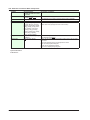
Symbols used in operational explanation
In the pages explaining operation (chapter 1 to 4), the following symbols are used to
distinguish the descriptions.
Procedure
iv
This subsection contains the operating procedure used to carry out
the function described in the current section. All procedures are
written with inexperienced users in mind; experienced users may
not need to carry out all the steps.
Explanation
Explanation gives information such as limitations related the
procedure.
Note
Calls attention to information that is important for proper operation
of the instrument.
IM 04L41B01-62EN
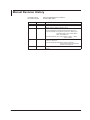
Manual Revision History
Document name: Document number:
IM 04L41B01-62EN
DXA170 DAQStudio User’s Manual
IM 04L41B01-62EN
Edition
1st
2nd
Revised
January, 2009
April 4, 2009
3rd
March, 2010
4th
August, 2010
5th
May 2014
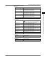
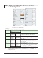
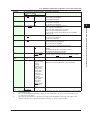
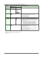
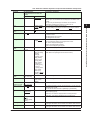
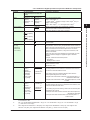
Description of Revisions and DAQStudio Software Version
New, R1.01
Corrections, new software display languages added (Chinese,
German, French, Russian, Korean), R1.02
Added components, changed screens, and added/changed
component attributes to support DXAvanced R4, R2.01.01
Components added: Group name, System icon, Memory bar,
Time label, Batch group number, Batch
name, and Modbus In.
Component attribute name change: Batch number --> Batch
group number
Added component attributes to support DXAvanced firmware
version 4.11, R3.01.01
Component attribute added: Batch name components,
Communication input components,
Modbus in components
Changed to support SMARTDAC+ GX/GP R2
R4.01.01
v
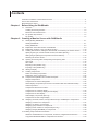
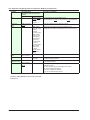
Contents
Terms and Conditions of the Software License................................................................................. ii
How to Use This Manual................................................................................................................... iv
Manual Revision History....................................................................................................................v
Chapter 1 Before Using the DAQStudio
1.1 Overview............................................................................................................................... 1-1
Creating and Saving Screens............................................................................................... 1-2
Monitor Screen Creation Flow.............................................................................................. 1-3
1.2 PC System Requirements.................................................................................................... 1-4
PC System............................................................................................................................ 1-4
Chapter 2 Creating a Monitor Screen with DAQStudio
2.1 Starting/Exiting DAQStudio................................................................................................... 2-1
Starting DAQStudio.............................................................................................................. 2-1
Exiting DAQStudio................................................................................................................ 2-2
2.2 Explanation of the Main Screen of DAQStudio..................................................................... 2-3
2.3 Explanation of Menus, Icons, and Shortcut Keys............................................................... 2-10
2.4 Creating New Screens, Setting the Grid Interval, and Switching the Screen Version........ 2-12
Specifying the type, recorder release number, and batch (DX only).................................. 2-12
Setting the grid (setting the component movement interval).............................................. 2-13
Switching the screen version.............................................................................................. 2-14
2.5 Opening and Saving Files and Exporting and Importing Files............................................ 2-16
Open a file.......................................................................................................................... 2-16
Save a file........................................................................................................................... 2-17
Exporting a File (GX/GP only)............................................................................................ 2-18
Importing a File (GX/GP only)............................................................................................. 2-18
2.6 Adding a Display................................................................................................................. 2-19
2.7 Creating Components......................................................................................................... 2-20
Notes on Creating Components......................................................................................... 2-21
Explanation of the Components ........................................................................................ 2-22
2.8 Components Explanation and Creation Examples............................................................. 2-24
Diagram Components......................................................................................................... 2-24
Components for Channel Assignment................................................................................ 2-24
Status display components (can be set on recorders other than DXAdvanced R3)........... 2-28
Label components.............................................................................................................. 2-29
Components with action functions...................................................................................... 2-30
Components for comment display...................................................................................... 2-32
Components for summary display and list display.............................................................. 2-33
Components for trend display............................................................................................. 2-34
Scale display components (DX only).................................................................................. 2-35
Components for static image display.................................................................................. 2-36
2.9 Assigning Channels, Alarms, Groups, Batch Groups, and Bitmaps to Components.......... 2-37
Assigning a channel to a component.................................................................................. 2-37
Assigning an alarm to a component .................................................................................. 2-37
Assigning group numbers to components.......................................................................... 2-38
Assigning batch numbers to components (DX only)........................................................... 2-38
Assigning images (PNG/BMP) to components................................................................... 2-39
2.10 Editing Components and the Screen.................................................................................. 2-40
Selection and deselection of components, movement, magnification/contraction.............. 2-40
Copy/Cut/Paste/Delete/Add for components and screens................................................. 2-43
vi
IM 04L41B01-62EN
Contents
Undo/Redo of a screen or component editing operation.................................................... 2-45
2.11 Arranging Components....................................................................................................... 2-46
2.12 Setting Attributes................................................................................................................. 2-53
Setting screen attributes .................................................................................................... 2-53
Setting component attributes ............................................................................................. 2-54
1
2
Chapter 3 Detailed Information for Attributes of Screens and Components
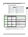
3.1 Screen Attributes.................................................................................................................. 3-1
3.2 Component ID No. and Number of Components which can be Created on one screen...... 3-3
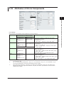
3.3 Common Attributes of Components...................................................................................... 3-5
Explanation of choices and set values.................................................................................. 3-5
Explanation of common attributes........................................................................................ 3-5
Action settings (GX/GP)or Synchronize action (DX)............................................................. 3-8
3.4 Attributes of Simple Digital Components............................................................................ 3-10
3.5 Attributes of Digital Components........................................................................................ 3-12
3.6 Attributes of Simple Bar Graph Components...................................................................... 3-14
3.7 Attributes of Bar Graph Components.................................................................................. 3-17
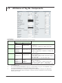
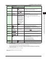
3.8 Attributes of Tag No. Components...................................................................................... 3-20
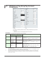
3.9 Attributes of Tag String/Tag Comment Components........................................................... 3-22
3.10 Attributes of Unit Components............................................................................................ 3-24
3.11 Attributes of Span/Span Upper Limit/Span Lower Limit Components................................ 3-26
3.12 Attributes of Alarm Indicator Components.......................................................................... 3-28
3.13 System Icon Component Attribute...................................................................................... 3-31
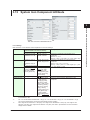
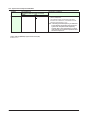
3.14 Attribute of Memory Bar Components................................................................................ 3-33
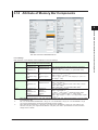
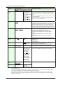
3.15 Attributes of DateTime Component / Time Label Component............................................ 3-36
3.16 Attributes of Batch Group Number Components................................................................ 3-39
3.17 Attributes of Batch Name Components.............................................................................. 3-41
3.18 Attributes of Group Name Components.............................................................................. 3-44
3.19 Attributes of Label Components......................................................................................... 3-47
3.20 Attributes of Button Operation Components/Push Button Components............................. 3-49
3.21 Attributes of DOIntSwitch Components / Switch Components........................................... 3-53
3.22 Attributes of Communication Input Components................................................................ 3-56
3.23 Attributes of Digital Operation Components / Modbus In Components.............................. 3-58
3.24 Attributes of Comment Box Components........................................................................... 3-61
3.25 Attributes of Comment Block Components......................................................................... 3-63
3.26 Attributes of Alarm Summary Components / Alarm List Components................................ 3-65
3.27 Attributes of Message Summary Components / Message List Components...................... 3-68
3.28 Attributes of Trend Components......................................................................................... 3-71
3.29 Attributes of Scale Components......................................................................................... 3-76
3.30 Attributes of Line Components........................................................................................... 3-79
3.31 Attributes of Rectangle Components.................................................................................. 3-81
3.32 Attributes of Circle Components......................................................................................... 3-83
3.33 Attributes of Image Components/Bitmap Components....................................................... 3-85
Chapter 4 Communication with GX/GP/DX Recorder
4.1 Receiving Display Data from GX/GP/DX Recorder.............................................................. 4-1
Notes on Firewalls................................................................................................................ 4-3
4.2 Sending Display Data to GX/GP/DX Recorder..................................................................... 4-4
Chapter 5 Messages and Handling Methods
5.1 List of Messages................................................................................................................... 5-1
5.2 Version Information............................................................................................................... 5-4
5.3 Changing the Screen Version............................................................................................... 5-5
Index
IM 04L41B01-62EN
vii
3
4
5
Index
Chapter 1
Before Using the DAQStudio
1.1
Overview
1
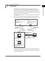
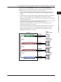
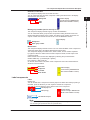
CF Card (DX)
Display data
Custom01.GCD to Custom30.GCD
Image file (.png)
Settings file (Setting.GCS)
Display data
Internal1.CDC to Internal3.CDC
External1.CDC to External25.CDC
Image file (.bmp)
Settings file (Setting.CDS)
Reading
display data
and image files
GX/GP
(Installing a SD Card)
Saving
display data
and image files
Receiving display data,
settings files, and
image files
Reading display data,
settings files, and
image files
PC
DAQStudio
Ethernet
DX
(Installing a CF Card)
Internal1.CDC to Internal3.CDC
External1.CDC to External25.CDC
Bitmap file (.bmp)
Settings file (Setting.CDS)
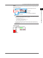
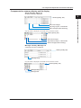
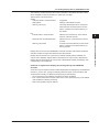
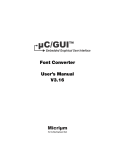
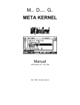
Settings files contain GX/GP/DX recorder settings that have been converted to data.
When receiving screen data from the GX/GP/DX recorder, screen data and image files
are received together. By receiving settings files, the GX/GP/DX recorder’s setups can
be reproduced on DAQStudio.
IM 04L41B01-62EN
3
4
Index
Sending display data
and image files
Custom01.GCD to Custom30.GCD
Image file (.png)
Settings file (Setting.GCS)
2
5
SD Card (GX/GP)
Saving display data,
settings files, and
image files
Before Using the DAQStudio
DAQStudio is a software application used to create original monitor screens for
displaying data measured on GX10/GX20/GP10/GP20 paperless recorders (hereafter
called the GX/GP) and DX1000/DX1000N/DX1000T/DX2000/DX2000T paperless
recorders (hereafter called the DX). For monitoring of measuring data, it is possible to
assign channels to digital parts, trend parts, etc., and diagram components can be used
to create monitor screens matched to site images.
The monitor screens that you create can be displayed using the custom display function
of the GX/GP/DX.
You can also use DAQStudio to receive custom display data from a GX/GP/DX and
edit it and send the display data created with DAQStudio to a GX/GP/DX. Data can be
exchanged via Ethernet or external storage media (SD memory card or CF card).
1-1
1.1 Overview
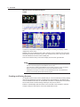
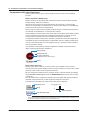
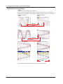
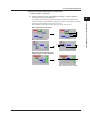
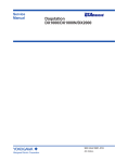
Monitor Screen Creation Examples
GX/GP
DX
A screen is composed of multiple parts, and background setting and display of static
images also can be done.
Multiple parts can be related to each other, and parts can be combined with other parts.
Measuring channels are allotted to parts. Size, character font, color, unit, group control,
and other attributes are set for each created part.
Parts can be laid out freely in the screen display area at screen grid intervals.
Note
• Monitor screens are displayed correctly only when the language kind of the GX/GP/DX
recorder and the language kind of DAQStudio are the same.
• As screens being created with DAQStudio cannot display measuring values, the display
differs from the custom display execution screen of the GX/GP/DX recorder.
• DAQStudio cannot open a connection with the GX/GP/DX recorder if the GX/GP/DX is
already communicating with another software program.
Creating and Saving Screens
An original monitor screen can be created newly or it can be created by receiving display
data from the GX/GP/DX recorder and editing them with DAQStudio. The display data
from the GX/GP/DX recorder can be retrieved via Ethernet or display data of the GX/GP/
DX recorder saved to external storage media (CF card) can be read in.
Edited or created display data are stored on the hard disk of the computer or external
storage media (CF card) and are sent to the GX/GP/DX recorder.
1-2
IM 04L41B01-62EN
1.1 Overview
1
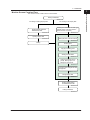
Monitor Screen Creation Flow
Before Using the DAQStudio
The monitor screen creation flow is shown below.
Starting DAQStudio
2
►Section 2.1
For editing of existing display data
For creating a new display data
3
Receiving display data from
GX/GP/DX recorder
►Section 4.1
Selecting the GX/GP/DX recorder type,
release number, and batch function
(Batch function is only DX.)
4
►Section 2.4
Opening display data
►Section 2.5
5
Setting the parts movement interval
►Section 2.4
Editing
Creating parts
Index
►Section 2.7
Copying or deleting parts
►Section 2.10
Setting parts attributes
►Section 2.12
Assigning channels, alarms,
groups, batch groups, and
bitmaps to components.
►Section 2.9
Changing parts arrangement and
background
►Section 2.11, 2.12
Saving display data
►Section 2.12
Sending display data to
the GX/GP/DX recorder
►Section 4.2
Exiting DAQStudio
►Section 2.1
IM 04L41B01-62EN
1-3
1.2
PC System Requirements
PC System
• Supported Operating Systems (OS)
Run DAQStudio under any of the following operating systems.
• Windows Vista Home Premium SP2 (excluding the 64-bit edition)
• Windows Vista Business SP2 (excluding the 64-bit edition)
• Windows 7 Home Premium SP1 (32-bit and 64-bit editions)
• Windows 7 Professional SP1 (32-bit and 64-bit editions)
• Windows 8 (32-bit and 64-bit editions)
• Windows 8.1 (32-bit and 64-bit editions)
• Windows 8 Pro (32-bit and 64-bit editions)
• Windows 8.1 Pro (32-bit and 64-bit editions)
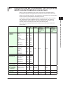
The language displayed by the software under different language versions of the OS
are as follows.
OS Language
Japanese
English
Chinese
German
French
Russian
Korean
Software Language
Japanese
English
Chinese
German
French
Russian
Korean
• PC
Machine type
A PC that runs one of the OS above, and that meets the following CPU and memory
requirements.
CPU and main memory capacity
Intel Pentium 4, 3 GHz or faster x64 or x86 processor
2 GB or more of memory
• Hard disk
Free disk space: 100 MB or more
• CD-ROM Drive
CD-ROM drive compatible with the OS. Used for installation.
• Mouse
Mouse supported by the OS
• Monitor
A video card that is recommended for the OS and a display that is supported by the
OS, has a resolution of 1024×768 or higher, and that can show 65,536 colors (16-bit,
high color) or more.
• Communication Port
Ethernet port (10Base-T) supported by the OS. Also, TCP/IP protocol is required to be
installed.
1-4
IM 04L41B01-62EN
Chapter 2
Creating a Monitor Screen with DAQStudio
2.1
Starting/Exiting DAQStudio
1
Starting DAQStudio
2
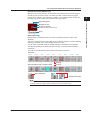
Procedure
Components
bar
Display
name
Status
area
Screen
version
3
Attribute area
Menu bar
Tool bar
4
5
Display list
area
Index
List area
spreader
Work area
Channel list
Batch/group list
or group list
Image list
Mouse coordinates
Arrangement
bar
Screen size
Screen construction area
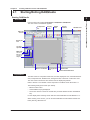
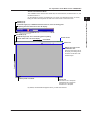
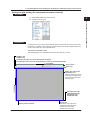
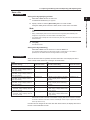
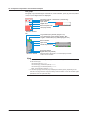
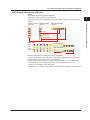
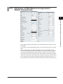
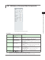
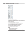
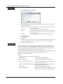
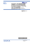
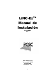
Explanation
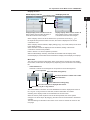
The Main screen is composed of Menu bar, Tool bar, Display list area, Channel/Alarm list
area, Components bar, Attribute area, Arrangement bar, and Screen construction area.
The main screen size is fixed. The GX20 screen is displayed by default.
Refer to Section 2.2 for details of each component in the Main screen. ►Section 2.2
The following settings are active upon startup.
• Batch function is OFF
• Channel/Alarm list page displayed
• The screen version is shown as “GX/GP R2” (recorder release number: GX20/GP20
R2).
For the display when receiving screen data from the GX/GP/DX recorder ►Section 4.1
When creating a new screen, you can set the GX/GP/DX recorder release number and
batch (DX only). ►Section 2.4
IM 04L41B01-62EN
Creating a Monitor Screen with DAQStudio
From the Start menu select All Programs > DAQStudio > DAQStudio.
The main screen of DAQStudio appears.
2-1
2.1 Starting/Exiting DAQStudio
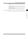
Exiting DAQStudio
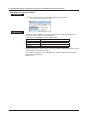
Procedure
1. Select File > Exit from the menu bar or click the “×” mark at the right top of the
Main screen.
2. Exit from DAQStudio is made when there is no screen being edited.
If there is a screen being edited, a dialog message confirming whether the screen is to be
saved or not is displayed.
3. Click [Yes] or [No]. (Exit operation is cancelled when [Cancel] is clicked.)
2-2
IM 04L41B01-62EN
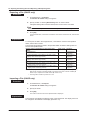
2.2
Explanation of the Main Screen of DAQStudio
The configuration of the Main screen of DAQStudio is shown below.
Display
name
Status
area
Screen
version
2
Attribute area
Creating a Monitor Screen with DAQStudio
Components
bar
Menu bar
Tool bar
3
Display list
area
4
5
List area
spreader
Work area
Index
Channel list
Batch/group list
or group list
Image list
Mouse coordinates
Arrangement
bar
Screen size
Screen construction area
The icon names of each bar are shown below. Refer to Section 2.3 for the icon functions
and the shortcut keys.
Menu bar
This is composed of File, Edit, View, Screen, Communication, and Help.
Tool bar
New
Open
Save
Receive
Send
Add display
Version
Redo
Past
Cut
IM 04L41B01-62EN
1
Undo
Copy
2-3
2.2 Explanation of the Main Screen of DAQStudio
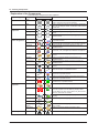
Component bar
The components that are available change when you switch the screen version.
Edit
GX/GP
Move
Line
Rectangle
Circle
Label
Unit
Simple digital
Digital
Simple bar
Bar
Image
Message summary
Alarm summary
Digital operation
Button operation
Memory bar
Edit
Trend
Alarm indicator
Span
DOIntSwitch
System icon
Group name
Batch name
Tag string
TagNo.
User name
Date time
DX
Move
Line
Rectangle
Circle
Label
TagComment
Unit
Simple digital
Digital
Simple bar
SpanU
SpanL
Alarm indicator
Bar
Comment box
Trend
TagNo.
Modbus In*
Batch name*
Batch group number*
Time label*
Memory bar*
System icon*
Group name*
Comm. In
Message list
Alarm list
Bitmap
Push button
*Not displayed with screen version 3.
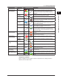
Arrangement bar
Left
Comment block
Switch
Distribute horizontally
Horizontal Center
Right
Distribute vertically
High
Wide
Bottom
Vertical Center
Top
2-4
To Back
To Front
To Bottom
To Top
IM 04L41B01-62EN
2.2 Explanation of the Main Screen of DAQStudio
1
Display list area
GX/GP display name list
List of display names
displayed at the time
of start
DX display name list
2
3
Displays display names from No. 2 to No. 30
When a display name is clicked, the display of
the Screen construction area changes.
Displays display names from No. 4 to No. 28
When a display name is clicked, the display
of the Screen construction area changes.
When a display name in the list is clicked or the up and down arrow keys (↑, ↓) of
the keyboard are pressed to select a screen, the screen is displayed in the screen
construction area.
When a display name is selected, display editing (Copy, Cut, Paste, Delete) can be done
in the display list area.
When a location outside the Display list area is selected, editing of the Screen
construction area becomes possible.
Refer to Section 2.10 for the operation procedure.
With the initial settings at startup, the GX/GP shows blank data for display name
CustomDisplay01, and the DX shows blank data for display names Display1 to Display3.
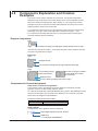
Work area
The work area contains the tabs below. When screen data is received from the GX/GP/
DX recorder, the lists that are displayed vary depending on the information in the settings
file.
• Channel/Alarm list
Channels or alarms can be assigned to components for channel assignment.
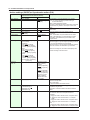
List area spreader
Status with Alarm setting (Green)
The alarm information is hidden when clicked.
Alarm information
Status without Alarm setting (Gray)
The alarm information is displayed when clicked.
Channel No., Tag No. or Tag comment
The Channel/Alarm information set at the GX/GP/DX recorder is displayed as Channel
No., Tag No. or Tag Comment. At this time, the alarm information is included.
Switching of the display format can be selected from the View menu.
When the mouse pointer is placed onto the list area spreader, the mouse pointer
changes to an arrow shape. By dragging, the View area can be increased or decreased
vertically.
The initial settings for the Main screen when a new screen is created are shown on the
next page.
IM 04L41B01-62EN
Creating a Monitor Screen with DAQStudio
2-5
4
5
Index
2.2 Explanation of the Main Screen of DAQStudio
For GX10/GP10:
I/O channel-unit0
I/O channel-unit1
I/O channel-unit2
I/O channel-unit3
I/O channel-unit4
I/O channel-unit5
I/O channel-unit6
Math channel
Comm channel
[0001] to [0016], [0101] to [0116], [0201] to [0216]
[1001] to [1016], [1101] to [1116], [1201] to [1216], [1301] to
[1316], [1401] to [1416], [1501] to [1516]
[2001] to [2016], [2101] to [2116], [2201] to [2216], [2301] to
[2316], [2401] to [2416], [2501] to [2516]
[3001] to [3016], [3101] to [3116], [3201] to [3216], [3301] to
[3316], [3401] to [3416], [3501] to [3516]
[4001] to [4016], [4101] to [4116], [4201] to [4216], [4301] to
[4316], [4401] to [4416], [4501] to [4516]
[5001] to [5016], [5101] to [5116], [5201] to [5216], [5301] to
[5316], [5401] to [5416], [5501] to [5516]
[6001] to [6016], [6101] to [6116], [6201] to [6216], [6301] to
[6316], [6401] to [6416], [6501] to [6516]
[A001] to [A050]
[C001] to [C050]
For GX20/GP20:
I/O channel-unit0
I/O channel-unit1
I/O channel-unit2
I/O channel-unit3
I/O channel-unit4
I/O channel-unit5
I/O channel-unit6
Math channel
Comm channel
[0001] to [0016], [0101] to [0116], [0201] to [0216]
[1001] to [1016], [1101] to [1116], [1201] to [1216], [1301] to
[1316], [1401] to [1416], [1501] to [1516]
[2001] to [2016], [2101] to [2116], [2201] to [2216], [2301] to
[2316], [2401] to [2416], [2501] to [2516]
[3001] to [3016], [3101] to [3116], [3201] to [3216], [3301] to
[3316], [3401] to [3416], [3501] to [3516]
[4001] to [4016], [4101] to [4116], [4201] to [4216], [4301] to
[4316], [4401] to [4416], [4501] to [4516]
[5001] to [5016], [5101] to [5116], [5201] to [5216], [5301] to
[5316], [5401] to [5416], [5501] to [5516]
[6001] to [6016], [6101] to [6116], [6201] to [6216], [6301] to
[6316], [6401] to [6416], [6501] to [6516]
[A001] to [A100]
[C001] to [C500]
For DX1000:
Meas channel
Math channel
[CH001] to [CH012]
[CH101] to [CH124]
For DX2000:
Meas channel
Math channel
Ext channel
2-6
[CH001] to [CH048]
[CH101] to [CH160]
[CH201] to [CH440]
IM 04L41B01-62EN
2.2 Explanation of the Main Screen of DAQStudio
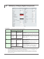
Batch/Group list
Group list
2
3
4
Groups used
Drag onto a component
to assign
5
Index
Click to hide the batch group numbers
Batch group numbers used
Drag onto a component to assign
Click to show the batch group numbers
Batch and Group display range
Type
DX1000
DX2000
Batch
[Batch 01] to [Batch 06]
DX2000 [Batch 01] to [Batch 12]
Group
[Group 01] to [Group 06]
[Group 01] to [Group 12]
The maximum batch number is the number of multibatches recorded in the DX recorder
settings file.
Group display range
Type
GX10/GP10
GX20/GP20
DX1000
DX2000
IM 04L41B01-62EN
1
Creating a Monitor Screen with DAQStudio
Batch/Group list, or Group list
Shows the batches and groups, and enables assignment of batch or group to
components. If MultiBatch is On on the DX recorder the Batch/Group list is displayed,
and if Batch is turned Off or On, the Group list is displayed.
Components to which batch items can be assigned:
Alarm list, Message list,
Batch group number,
Batch name, Memory bar
Components to which groups can be assigned:
Trend, Scale, Group name
Group
[Group 01] to [Group 30]
[Group 01] to [Group 60]
[Group 01] to [Group 10]
[Group 01] to [Group 36]
2-7
2.2 Explanation of the Main Screen of DAQStudio
• Image list
Displays a list of data in the image folder. On the GX/GP, the data in this list can be
assigned to the display background, waveform area background of image components
and trend components, and scale images. On the DX, the data in this list can be
assigned to bitmap components and scale components.
Image folder: Bitmap files used by DAQStudio must be placed in a single location.
This specific folder is called the bitmap folder.
Components to which images can be assigned:
GX/GP:Image, trend (waveform area background and scale image), and display
background
DX: Bitmap, scale
Drag the bitmap onto a component to assign
Bitmap file name
Only the data that can be displayed by a GX/GP/DX recorder is shown in the image
list. Only the images meeting the following criteria can be displayed by the GX/GP/DX
recorder.
GX/GP
• File type: PNG files (*.png)
• Image size: 800 x 600 pixels (WxH) or less (GX20/GP20)
640 x 480 pixels (WxH) or less (GX10/GP10)
• File name: Up to 64 characters including the extension
• 24 bit RGB or 32 bit RGBA full color format
DX
• File type: Bitmap files (*.bmp)
• Image size: 640 x 480 pixels (WxH) or less
• 256 colors or less, uncompressed
• File name: Up to 51 characters including the extension
The list is sorted in order by the character code of the file name.
Immediately after starting DAQStudio, creating a new screen, or receiving screen data
from the GX/GP/DX recorder, the image folder is placed in the following location.
[Drv]:\Users\[user name]\AppData\Roaming\DAQStudio.
Where [Drv] is the drive on which the OS was installed.
Where [user name] is the name of the user who is using the OS.
Immediately after a file is saved, or immediately after a file is opened, the image folder
becomes the target folder for saving screen construction files.
Immediately after startup, or immediately after a new file is created, the image folder
is cleared.
Updating the image list
The image list is updated immediately after startup, immediately after a new file
is created, immediately after opening a file, immediately after saving a file, and
immediately after receiving screen data from the GX/GP/DX recorder.
Also, if you specify a folder and image in the attributes of image components and
scale components, the specified data is copied to the image folder. Immediately
thereafter, the image list is updated.
2-8
IM 04L41B01-62EN
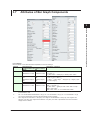
2.2 Explanation of the Main Screen of DAQStudio
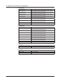
Screen Construction Area
The available screen versions are GX/GP R2, DX Advanced R3, DX Advanced 4.01, and
DX Advanced R4.11.
On the GX/GP R2 screen, DX Advanced 4.01 screen, and DX Advanced R4.11 screen,
hiding the status area expands the edit area of the screen construction area.
2
Creating a Monitor Screen with DAQStudio
DX1000 (0, 24)
DX2000 (0, 40)
1
3
Coordinate origin (0,0). In DXAdvanced R4.01 and R4.11, this is the starting point
for plotting when the status area is set to No display.
4
For GX/GP (0, 30)
Coordinate origin (0,0). This is the starting point for plotting
when the status area is set to No display.
X-coordinate
Screen version
5
Status area
Y-coordinate
Editing area of the screen
construction area
When the status area is set to
No display, the editing area of
the screen construction area
becomes larger.
Mouse pointer coordinate
Screen size
GX10/GP10: 640 x 480 pixels
GX20/GP20: 800 x 600 pixels
DX1000: 320 x 240 pixels
DX2000: 640 x 480 pixels
By default, the GX20/GP20 appears when you start the software.
IM 04L41B01-62EN
2-9
Index
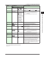
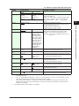
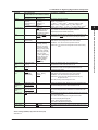
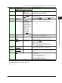
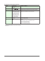
2.3
Explanation of Menus, Icons, and Shortcut
Keys
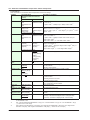
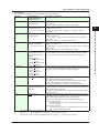
Menu bar contents, icons, and shortcut keys are shown in a list.
The icons are arranged on the Tool bar and on the Arrangement bar.
File menu
Menu name
File
New
Icon
–
Open
Ctrl+O
Save
Ctrl+S
Explanation
–
All present screens are discarded and a new screen is
created.
A screen construction file is loaded.
Save as
–
–
Export
–
–
Import
–
–
Exit
–
–
A screen construction file is saved to the save folder by
overwriting.
A save folder is specified and the screen construction file is
saved to that folder.
In the specified folder, a sub folder is created for each screen
construction file, and the file is saved (GX/GP’s external
media format).
A screen construction file saved in GX/GP’s external media
format is imported and displayed.
The application is exited.
Shortcut keys
–
Ctrl+Z
Ctrl+Y
Ctrl+X
Explanation
–
Undoes the previous edit operation.
Redoes the undone edit operation.
The object is moved to the clipboard.
Copy
Ctrl+C
The object is copied to the clipboard.
Past
Ctrl+V
The object is copied from the clipboard and moved to the
specified location.
All components in the Screen construction area are selected.
The object is deleted.
A new screen is added to the display list
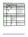
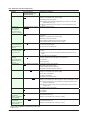
Edit menu
Menu name
Edit
Undo
Redo
Cut
Select All
Delete
Add Display
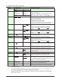
View menu
Menu name
View
Channel
TagNo.
TagComment
Grid
Display List
Operate Area
Attribute Area
Part Bar
Arrange Bar
Language
Icon
–
–
–
Icon
–
–
–
–
–
–
–
–
–
–
–
View – Grid menu
Menu name
1Dot
5Dot
10Dot
20Dot
50Dot
2-10
Shortcut keys
–
Ctrl+N
Icon
–
–
–
–
–
Ctrl+A
Delete
–
Shortcut keys
–
–
–
–
–
–
–
–
–
–
–
Explanation
–
The Channel No. is displayed in the Channel list.
The Tag No. is displayed in the Channel list.
The Tag Comment is displayed in the Channel list.
The Grid interval is displayed.
The display list is shown or hidden.
The operation area is shown or hidden.
The attribute area is shown or hidden.
The parts list is shown or hidden.
The arrangement bar is shown or hidden.
The display language is switched. The default setting
depends on the OS language.
English, Japanese, Chinese, French, German, Korean,
Russian
Shortcut keys
–
–
–
–
–
Explanation
The screen grid interval is set to 1 dot.
The screen grid interval is set to 5 dots.
The screen grid interval is set to 10 dots.
The screen grid interval is set to 20 dots.
The screen grid interval is set to 50 dots.
IM 04L41B01-62EN
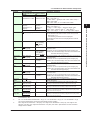
2.3 Explanation of Menus, Icons, and Shortcut Keys
Screen menu
Icon
–
–
–
–
–
Arrangement menu
Menu name
Arrangement
Left
Icon
1
Explanation
–
Sets the screen to the DXAdvanced R3 version.
Sets the screen to the DXAdvanced 4.01 version.
Sets the screen to the DXAdvanced 4.11 version.
Sets the screen to the GX/GP R2 version.
2
3
Shortcut keys
–
–
Explanation
–
The left edge of the selected component is arranged aligned
with the left edge of the reference component.
Horizontal Center
–
Right
–
The center in horizontal direction of the selected component
is arranged aligned with the center in horizontal direction of
the reference component.
The right edge of the selected component is arranged aligned
with the right edge of the reference component.
Top
–
The top edge of the selected component is arranged aligned
with the top edge of the reference component.
Vertical Center
–
Bottom
–
The center in vertical direction of the selected component is
arranged aligned with the center in vertical direction of the
reference component.
The bottom edge of the selected components are aligned with
the reference component.
Distribute
horizontally
–
The selected components are distributed proportionally in the
horizontal direction.
Distribute vertically
–
The selected components are distributed proportionally in the
vertical direction.
Height
–
The height of the selected component is matched to the
height of the reference component.
Width
–
The width of the selected component is matched to the width
of the reference component.
To Top
–
The selected component is arranged for display on the
foremost plane.
To Bottom
–
The selected component is arranged for display on the
rearmost plane.
To Front
–
The selected component is arranged for display one plane to
the front.
To Back
–
The selected component is arranged for display one plane to
the rear.
Shortcut keys
–
–
–
Explanation
–
A screen construction file is received from the GX/GP/DX
recorder.
A screen construction file is sent to the GX/GP/DX recorder.
Shortcut keys
–
F1
–
Explanation
–
Displays the user’s manual.
The About dialog is displayed.
–
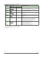
Communication menu
Menu name
Communication
Receive
Icon
–
Send
Help menu
Menu name
Help
User’s manual (I)
About
IM 04L41B01-62EN
Shortcut keys
–
–
–
–
–
Icon
–
–
Creating a Monitor Screen with DAQStudio
Menu name
Screen
DX Advanced 3(3)
DX Advanced 4.01(0)
DX Advanced 4.11(1)
GX/GP R2(2)
2-11
4
5
Index
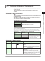
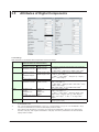
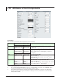
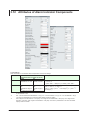
2.4
Creating New Screens, Setting the Grid
Interval, and Switching the Screen Version
When creating a new screen, you can set the GX/GP/DX recorder type, recorder release
number, and batch (DX only), and set the grid interval. The GX/GP/DX recorder settings
that can be entered when creating a new screen are limited to the type, GX/GP/DX
recorder release number, and batch (DX only).
Because the GX/GP/DX recorder settings file is also received when receiving custom
display screen data from the GX/GP/DX recorder, you can edit and create screens
starting from the setting conditions of the GX/GP/DX recorder to which you connect.
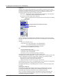
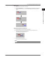
Specifying the type, recorder release number, and batch (DX only)
Specify the screen-data target type (GX10/GP10, GX20/GP20, DX1000, or DX2000), the
GX/GP/DX recorder release number, and the batch on/off/MultiBatch setting (DX only).
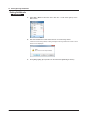
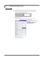
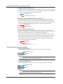
Procedure
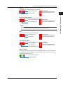
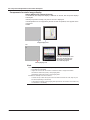
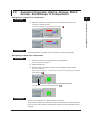
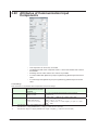
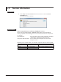
1. Select File > New from the menu bar or click the New icon.
The New dialog box appears.
The initially set screen is [GX20/GP20] and [R2].
Display of GX20/GX20
Display of DX2000
2. Set the type and recorder release number, and then click [OK].
For the DX1000 or DX2000, specify the batch setting in addition to the type and
recorder release number.
OK: The displayed display data are discarded and a new screen is created.
The size of the screen construction area for the selected model is displayed.
Cancel: Return to the Main screen.
Explanation
When creating a new screen, specify the type, recorder release number, and batch.
The release number of the GX/GP/DX recorder you can connect to differs depending on
the recorder release number (screen version) set here.
See “Switching the Screen Version” in this section. When creating a new screen, the
Channel/Alarm list page appears in the work area. When creating a new screen, if
MultiBatch is selected under Batch, the Batch/Group list page appears in the work area,
and the Group list page is not displayed. When creating a new screen, if On or Off is
selected under Batch, the Group list page appears in the work area, and the Batch/Group
list page is not displayed.
2-12
IM 04L41B01-62EN
2.4 Creating New Screens, Setting the Grid Interval, and Switching the Screen Version
1
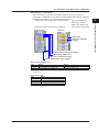
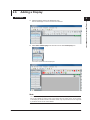
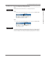
Setting the grid (setting the component movement interval)
Procedure
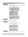
1. Select View > Grid from the menu bar.
2
2. Specify the screen grid.
Creating a Monitor Screen with DAQStudio
3
4
5
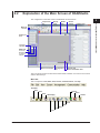
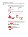
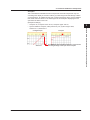
Explanation
Components can be moved in grid intervals. When components are moved, they can be
arranged in a condition with the left apex contacting the grid. The grid appears when it is
set to a value other than 1 Dot (default value).
The screen construction area
The following figure is a GX20/GP20 screen with the grid set to 10 Dot.
GX10/GP10, GX20/GP20 (0, 30)
DX1000 (0, 24)
DX2000 (0, 40)
Coordinate origin (0,0). This is the starting point for plotting
when the status area is set to No display (except for screen version DX Advanced R3).
X-coordinate
Screen version
Status area
Y-coordinate
Editing area of the screen
construction area
When the status area is set to
No display, the editing area of
the screen construction area
becomes larger.
GX10/GP10 (640, 480)
GX20/GP20 (800, 600)
DX1000 (320, 240)
DX2000 (640, 480)
Mouse pointer coordinate
IM 04L41B01-62EN
Screen size
GX10/GP10: 640 x 480 pixels
GX20/GP20: 800 x 600 pixels
DX1000: 320 x 240 pixels
DX2000: 640 x 480 pixels
2-13
Index
2.4 Creating New Screens, Setting the Grid Interval, and Switching the Screen Version
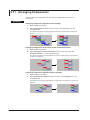
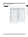
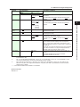
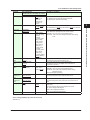
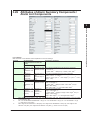
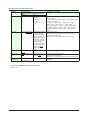
Switching the screen version
Procedure
1. On the Screen menu, click the appropriate screen version.
The screen version switches accordingly.
Explanation
The version of the GX/GP/DX recorder you can connect to differs depending on the
DAQStudio screen version. See the table below.
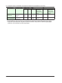
Screen version and GX/GP/DX recorder release number
Screen version
DX Advanced R3
DX Advanced R4.01
DX Advanced R4.11
GX/GP R2
Release number of compatible recorders
R3.01, R3.02, R3.03, R3.04
R4.01, R4.02
R4.11, R4.12, R4.19
R2.01
Note that switching the screen version can cause component attribute settings to change
or unsupported components to appear.
If you change the screen version and additional component attribute settings appear,
they are set to their defaults.
►Section 5.3
2-14
IM 04L41B01-62EN
2.4 Creating New Screens, Setting the Grid Interval, and Switching the Screen Version
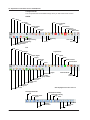
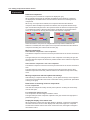
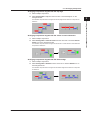
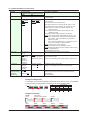
Screen version and GX/GP/DX recorder version data compatibility
DAQStudio
Screen data
Receive
Switch
Screen data
DXAdvanced
Release number:
R4.11, R4.12,
R4.16, R4.19
Send/Write
Receive
Screen data and
settings files
Switch
Screen data
Send/Write
DXAdvanced
Release number:
R4.01, R4.02
Receive
Switch
Screen data and
settings files
Screen data
DXAdvanced
Release number:
R3.01, R3.02,
R3.03, R3.04
Send/Write
Receive
Screen data and
settings files
IM 04L41B01-62EN
2
3
4
5
Index
GX/GP
Release number:
R2
Send/Write
Screen data and
settings files
1
Creating a Monitor Screen with DAQStudio
DAQStudio R3.01.01 is compatible with screen construction files from DX recorder
versions 3.01, 3.02, 3.03, 3.04, 4.01, 4.02, 4.11, R4.16, and R4.19.
• Communication with a GX/GP recorder whose recorder release number is R2 and
writing to screen construction files are available only when displaying GX/GP R2
screens.
• Communication with a DX recorder whose recorder release number is R3.01, R3.02,
R3.03, or R3.04 is available only when displaying DX Advanced R3 screens.
• Writing to DX Advanced R3 screen construction files is available only when displaying
DX Advanced R3 screens.
• Communication with a DX recorder whose recorder release number is R4.01 or R4.02
is available only when displaying DX Advanced R4.01 screens.
• Writing to DX Advanced R4.01 screen construction files is available only when
displaying DX Advanced R4.01 screens.
• Communication with a DX recorder whose recorder release number is R4.11, R4.12,
R4.16, or R4.19 is available only when displaying DX Advanced R4.11 screens.
• Writing to DX Advanced R4.11 screen construction files is available only when
displaying DX Advanced R4.11 screens.
2-15
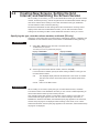
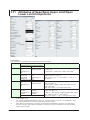
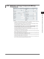
2.5
Opening and Saving Files and Exporting and
Importing Files
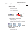
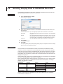
Open a file
Procedure
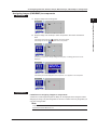
1. Select File > Open from the menu bar or click the Open icon.
The Open dialog box appears.
2. Specify the file location and the file name and click [Open].
When a screen being created is displayed, the following message appears.
3. Click [OK] if it is OK to discard the present screen.
The screen construction data are displayed.
Click [Cancel] if you do not want to discard the present screen.
File opening is cancelled and return is made to the Main screen. Explanation
For the GX/GP, the file names that the software can use are “Custom01.GCD” to
“Custom30.GCD.” For the DX, they are “Internal1.cdc” to “Internal3.cdc” and “External1.
cdc” to “External25.cdc.”
When a file is specified, all files with the above names are opened in the folder where
that files is located.
When a file is opened, the display name of the opened file is displayed in the display list
area. The display name can be changed on the attribute of the display (►Section 3.1).
When a display data is received from a GX/GP/DX recorder (►Section 4.2), the display
name defined on the GX/GP/DX recorder is displayed in the display list area.
The save destination folder of the opened file becomes the save object folder. When a
different file is opened, the save object folder becomes the folder of the opened file.
2-16
IM 04L41B01-62EN
2.5 Opening and Saving Files and Exporting and Importing Files
1
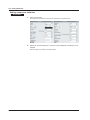
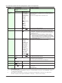
Save a file
Procedure
Saving a file by specifying a folder
2
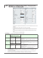
1. Select File > Save as from the menu bar.
2. Specify a folder or click the [New folder] button to create a folder.
3
If the [New folder] button has been clicked, enter a name for the new folder.
Note
• Network folders or compressed folders cannot be specified at the time of saving a display
data.
• Newly created display data must be saved. Save the image files (PNG or BMP) to be
assigned to components in the same folder as the display data.
• The display data or bitmap file must be saved every time they have been received from GX/
GP/DX recorder.
3. Click [OK].
The data are saved.
Select File > Save from the menu bar or click the Save icon.
In an already existing folder, the data will be saved by overwriting. If a new folder is
specified, the new folder becomes the target folder for saving files.
Explanation
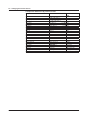
When the file save folder is specified, the entire information of the Display list area is
saved. The file name at the time of saving is as shown below.
GX/GP
Display names in the Display list area
at the initial setting*
CustomDisplay01
-2- (CustomDisplay02: when adding a
new data, “Copy”+ display name: of
the copy source)
-3- (CustomDisplay03: when adding a
new data, “Copy”+ display name: of
the copy source)
-4- (CustomDisplay02: when adding a
new data, “Copy”+ display name: of
the copy source)
-5- (CustomDisplay02: when adding a
new data, “Copy”+ display name: of
the copy source)
•••
-29- (CustomDisplay29: when adding a
new data, “Copy”+ display name: of
the copy source)
-30- (CustomDisplay30: when adding a
new data, “Copy”+ display name: of
the copy source)
The file name when
the file was saved
Custom01.gcd
Custom02.gcd
DX
Display names in the Display list
*
area at the initial setting
Display1
Display2
The file name when
the file was saved
INTERNAL1.cdc
INTERNAL2.cdc
Custom03.gcd
Display3
INTERNAL3.cdc
Custom04.gcd
-4- (Display4: when adding a new data,
“Copy”+ display name: of the copy
source)
-5- (Display5: when adding a new data,
“Copy”+ display name: of the copy
source)
•••
-27- (Display27: when adding a new
data, “Copy”+ display name: of the
copy source)
-28- (Display28: when adding a new
data, “Copy”+ display name: of the
copy source)
EXTERNAL1.cdc
Custom05.gcd
•••
Custom29.gcd
Custom30.gcd
EXTERNAL2.cdc
•••
EXTERNAL24.cdc
EXTERNAL25.cdc
* The display name can be changed on the attribute of the display (►Section 3.1). Display
data for item number 2 and later on the GX/GP or display data for item number 4 and later
on the DX is saved to a file when a screen is added (► section 2.6) or copied from another
screen (► section 2.10).
If the file name is changed to file name other than shown above, the display data cannot
be sent to the GX/GP/DX recorder.
IM 04L41B01-62EN
4
5
Index
Saving a file by overwriting
Creating a Monitor Screen with DAQStudio
The Browse for Folder dialog box appears.
2-17
2.5 Opening and Saving Files and Exporting and Importing Files
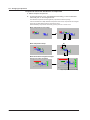
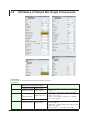
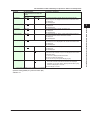
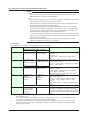
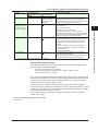
Exporting a File (GX/GP only)
Procedure
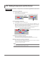
1. On the File menu, click Export.
The Browse for Folder dialog box appears.
2. Specify a folder or click the [New folder] button to create a folder.
If the [New folder] button has been clicked, enter a name for the new folder.
Note
Network folders or compressed folders cannot be specified when exporting a file.
3. Click [OK].
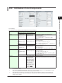
In the specified folder, a sub folder is created for each screen construction file, and the file is
saved.
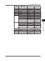
Explanation
For each piece of data in the image list area, a sub folder is created in the specified
folder, and the data is saved.
The exported image data is saved in the specified folder as follows. Settings files are
saved in the specified folder.
Display names in the Display list area at the initial
setting*
CustomDisplay01
Folder name
Saved file
01
-2- (CustomDisplay02: when adding a new data, “Copy”+
display name: of the copy source)
02
-3- (CustomDisplay03: when adding a new data, “Copy”+
display name: of the copy source)
03
Custom01.gcd
Image file**
Custom02.gcd
Image file**
Custom03.gcd
Image file**
•••
Custom29.gcd
Image file**
Custom30.gcd
Image file**
•••
-29- (CustomDisplay29: when adding a new data, “Copy”+
display name: of the copy source)
-30- (CustomDisplay30: when adding a new data, “Copy”+
display name: of the copy source)
29
30
* The display name can be changed on the attribute of the display (►Section 3.1). Display
data for item number 2 and later (GX/GP) is saved to a file when a screen is added (►
section 2.6) or copied from another screen (► section 2.10).
** The image file is saved only when it is in use.
Importing a File (GX/GP only)
Procedure
1. On the File menu, click Import.
The Browse for Folder dialog box appears.
2. Specify the folder.
3. Click [OK].
The screen construction file in the specified folder is displayed.
Explanation
The image list area displays the display name of the opened file. The display name can
be changed on the attribute of the display (►Section 3.1).
2-18
IM 04L41B01-62EN
2.6
Adding a Display
1
Procedure
2
1. Click the Display name in the display list area.
Creating a Monitor Screen with DAQStudio
Now the Add Display icon of the Tool bar can be selected.
3
4
5
2. Select Edit > Add Display from the menu bar or click Add Display icon.
Index
The screen construction area is displayed.
Note
The screens in the display list cannot be of different screen versions. If you switch the screen
that you have added (or another screen on the display list) to an earlier version, all the screens
on the display list will be switched to the earlier version. Any components that are not supported
by the earlier screen version will be deleted.
IM 04L41B01-62EN
2-19
2.7
Creating Components
Procedure
1. On the Components bar, click the icon for the component to be created.
2. Place the mouse pointer in the screen construction area and drag it.
A component with the dragged size is created.
3. Click the component.
The attributes of the selected components are displayed in the Attribute area.
Component type
ID numbers are allotted in the order
of creation.
The ID number differs depending
on the kind of component.
(Refer to Section 3.2.)
4. Set each attribute item.
2-20
For details, refer to Chapter 3.
IM 04L41B01-62EN
2.7 Creating Components
1
Explanation
Notes on Creating Components
After creating components aligned to the grid, if placed adjacent to each other they
overlap by 1 dot even though they do not appear to overlap. Separate components from
each other by at least 1 dot.
• If a component overlaps with a trend component, only the trend component is
displayed, regardless of how they are stacked.
• If two trend components overlap, only the one on top is displayed.
• If two image components overlap, only the one on top is displayed.
3
Display on the DX recorder when components overlap on the execution
screen
Limitations (A, B, and C) apply when components overlap on the execution screen. If
components with the same overlap restriction are overlapping, components placed under
the front component (i.e., in the background) are not displayed.
Overlap
restriction
None
A
B
C
Component name (attribute conditions)
Digital, bar, scale (kind: OFF), label, tag No., tag comment, simple digital, simple
bar graph, alarm mark, units, alarm indicator, span lower limit, span upper limit,
line, rectangle, circle, push button, switch, comment box, comment block, Comm
In, Group name, System icon, Memory bar, Time label, Batch group number,
Batch name, Modbus In
Scale (kind: ON)
Alarm list
Message list
Scale (kind: bitmap), bitmap
Trend
For example, if two components with Overlap restriction A are overlapping on the builder
screen, only the front component is displayed on the custom display execution screen of
the DX recorder.
Back
IM 04L41B01-62EN
Creating a Monitor Screen with DAQStudio
Display on the GX/GP recorder when components overlap
2
Front
2-21
4
5
Index
2.7 Creating Components
Explanation of the Components
The icons of the component bar are explained.
Component type
–
Component
name
Edit
Move
Diagram
components
Line
Rectangle
Circle
Components for
channel assignment
Simple digital
Digital
Simple bar
DX
Explanation
When the Edit icon is clicked, the components of the
Screen construction area can be selected.
When a scroll bar is shown in the screen construction
area, you can drag the screen construction area to move
the edit area.
Create a straight line connecting any two points.
Create a rectangle with any dragged points at opposite
corners.
Create a circle in a square with any dragged points at
opposite corners.
Create simple digital components displaying digital values
of specified channels.
Create components displaying digital values with Tag
Comment/Tag No./Channel No., Unit, and Alarm indicator.
Create simple bar components displaying a bar of a
specified channel.
Bar
Create components with tag comment, tag/tag No./
channel No., unit, and digital value added to a simple bar.
TagNo.
Create a component displaying the tag No. of a specified
channel.
Tag string
Create a component displaying the tag string of a
specified channel.
Create a component displaying the tag comment of a
specified channel.
TagComment
Unit
Span value
Status display
component
Icon
GX/GP
Create a component displaying the unit of a specified
channel.
Create a component displaying the upper and lower limit
values for the span of a specified channel.
SpanU
Create a component displaying the upper limit value for
the span of a specified channel.
SpanL
Create a component displaying the lower limit value for
the span of a specified channel.
Alarm indicator
Create a component displaying the alarm level of a
specified level, a specified channel.
Group name
Create a component displaying a group name.
System icon
Create a component displaying a system icon.
The kinds of system icon are: Memory sample, Alarm,
CF card, Math, Key lock, Email, Status, Key lock & email,
UserLock, and UserLock & status.
Create a component displaying the progress of memory
sampling.
Create a component displaying the current date and time.
Memory bar
Date time
Time label
Label components
Batch group
number
Create a component displaying the MultiBatch batch
group number.
Batch name
Create a component displaying the batch name.
Label
Create a label displaying an arbitrary text string.
Continued on the next page
2-22
IM 04L41B01-62EN
2.7 Creating Components
Component type
Components with
action functions
1
2
Button
operation
Create a component for displaying the state of a DO
channel or internal switch and controlling the on/off
state of the DO channel or internal switch through user
interaction.
Create a component for executing an action specified by
a function when the component is touched.
Push button
Create a push button.
Switch display
Create a switch component displaying the state of an
internal switch and performing ON/OFF switching of the
internal switch by operation.
Create a component for displaying the value of specific communication input data or writing a value as
communication input data.
Create a component displaying the value of specified
communication input data and writing values as
communication input data.
Create a component that displays the input value of
the communication channel set by the specified send
command number, or that writes temperature controller
and other SP values.
Create a component displaying a text string set at the DX
recorder.
Create a component displaying a comment block text
string set at the DX recorder
Icon
GX/GP
DX
Digital
operation
Comm In
Modbus In
Components for
comment display
Components for
summary display
Comment box
Comment
block
Alarm
summary
Create a component for display an alarm summary.
Message
summary
Create a component for display a message summary.
Alarm list
Create a component displaying an alarm list.
Message list
Create a component displaying a message list.
Scale components
Scale
Create a scale component displaying a scale plate used
together with trend display.
Components for
trend display
Trend
Create a trend component displaying the trend of a
specified group.
Components for
static image display
Image
Create a component for displaying a PNG static image.
Bitmap
Create a component displaying a static screen in bitmap
format.
Components for list
display
Component attributes
Refer to Chapter 3 for the creation number of components, the setting contents of
attributes, and the initial values.
IM 04L41B01-62EN
2-23
Creating a Monitor Screen with DAQStudio
Explanation
Component
name
DOIntSwitch
3
4
5
Index
2.8
Components Explanation and Creation
Examples
This section shows creation examples for components. Components created with
DAQStudio and components of the custom display screen of the GX/GP/DX recorder
differ in the display of measuring data, alarm display, etc. The components creation
examples are a mix of components created with DAQStudio and those of the custom
display execution screen of the DX recorder.
For components other than lines, the upper left apex of the component is the origin for
positioning on the grid, and the lower right apex is positioned at (origin - 1 dot).
For components that enable text label entry, any characters entered exceeding the
maximum allowed number are deleted.
Diagram Components
Line
Origin
You can draw a line going in the left/right or up/down direction from an origin.
If the start and end points overlap, 1 dot of space along the X axis is inserted. Start and
end points are positioned on the grid.
Rectangle
Origin
Background color
You can draw a rectangle from an origin toward the lower right.
Circle
Origin
A circle contacting a square
from the inside is drawn.
Background color
Even when a rectangle is specified,
a circle is drawn, but an ellipse
cannot be drawn.
A circle is drawn by dragging from a point of origin.
Components for Channel Assignment
Restrictions on channel assignments
The measured value of the assigned channel is displayed in the GX/GP recorder
operation screen or the DX recorder execution panel.
On a DX with the Math (/M1) and PROFIBUS-DP (/CP1) options, PROFIBUS-DP always
uses the communication input channels in the table below. The channels in the table
below cannot be assigned using DAQStudio.
Channels used with the /M1 and /CP1 option
Type
DX1000
DX2000
Communication input channels used
C01 to C24 (all)
C01 to C32
Simple digital
The digital value of the specified channel is displayed.
Simple digital display area (Frame: Sunken)
2-24
Digital value
***** is displayed with DAQStudio.
IM 04L41B01-62EN
2.8 Components Explanation and Creation Examples
Digital
Tag comment/tag No./channel No. of the measuring channel, unit, alarm indicator, and
digital value are displayed.
GX/GP
DX
Tag comment/Tag No./Channel No.
Unit
2
3
Digital value
***** is displayed with DAQStudio.
Unit
Alarm indicator
Note
• For the GX, the number of digits that appears in the text on a simple digital component and
digital components varies depending on the channel type.
I/O channel (not log): ********
I/O channel (log, one decimal place): ********
I/O channel (log, two decimal places): *********
Math, communication channel: **********
• For the DX, tags (tag comments) may be displayed as blank (space), depending on the
channel’s font setting. Refer to Section 3.3 for the character types provided for each font
(character size).
Simple bar graph
Bar graph and alarm mark are displayed.
Background
color: White
Direction: Horizontal
Direction: Vertical
IM 04L41B01-62EN
Creating a Monitor Screen with DAQStudio
Alarm indicator
1
2-25
4
5
Index
2.8 Components Explanation and Creation Examples
Bar graph
Bar graph, tag comment/tag No./channel No., alarm indicator, span, tag comment, alarm
mark, unit, and digital value are displayed.
GX/GP
Tag string / Tag No. / Channel No. (vertical only)
Alarm indicator
Span value
Digital value
Alarm set-point mark
Direction: Horizontal
Unit (only vertical)
Direction: Vertical
DX
Tag comment (only vertical) (Tag No.: On)
Tag / Channel No. (only vertical) (Tag No.: Off)
Tag No. / Channel No. (only vertical) (Tag No.: On)
Alarm indicator
Span value
Alarm set-point mark
Direction: Horizontal
Direction: Vertical
Unit (only vertical)
Digital value (only vertical)
Measured data is displayed on a custom display execution
screen of a DX recorder.
Note
• For the GX, the number of digits that appears in the text for digital values varies depending
on the channel type.
I/O channel (not log): ********
I/O channel (log, one decimal place): ********
I/O channel (log, two decimal places): *********
Math, communication channel: **********
• For the DX, tags (tag comments) may be displayed as blank (space), depending on the
channel’s font (tag comment or tag font) setting. Refer to Section 3.3 for the character types
provided for each font (character size).
2-26
IM 04L41B01-62EN
2.8 Components Explanation and Creation Examples
1
Tag No.
The tag No. of the specified channel is displayed.
Tag No. display area
Tag No. (string)
Vertical display
(can be set only in DXAdvanced
R4.01 screen and R4.11 screen)
2
3
Display of the tag comments of the specified channel
Tag comment display area
Tag comment (string)
Vertical display
(can be set only in DXAdvanced
R4.01 screen and R4.11 screen)
4
Note
For the DX, text may be displayed as blank (space), depending on the font setting. Refer to
Section 3.3 for the character types provided for each font (character size).
Unit
Unit (string)
Vertical display
(can be set only in DXAdvanced
R4.01 screen and R4.11 screen)
Span, SpanU, SpanL
The upper/lower limit value of the specified channel are displayed.
Span display area
Span lower limit /
Span upper limit (string)
Vertical display
(can be set only in DXAdvanced
R4.01 screen and R4.11 screen)
Alarm indicator
The alarm status of the specified channel is displayed. Refer to the User’s Manual (IM
04L41B01-01E or IM 04L42B01-01E) of the GX/GP/DX recorder for the alarm status
matching text and display color.
Alarm indictor display area
IM 04L41B01-62EN
5
Index
The unit of the specified channel is displayed.
Unit display area
Creating a Monitor Screen with DAQStudio
Tag string, TagComment
Alarm kind display
2-27
2.8 Components Explanation and Creation Examples
Status display components (can be set on recorders other than DXAdvanced
R3)
Group name
This component displays the group name corresponding to the specified group number.
You can create this group name component when you want to display components from
multiple groups, or if setting the status area to No display eliminates the group name.
Component area
Vertical display
(can be set only in DXAdvanced
R4.01 screen and R4.11 screen)
Group name
If you set Change group to On in the attribute
settings, the group name changes.
System icon
Creates a system icon for display in the status area. You can create icons that display
only the items you wish in the screen, for use when not displaying the status area.
Component frame
The size of the icon component frame is set under Icon size in the attribute settings.
GX/GP
Memory sample
Alarm
SD card
Math
Operation Lock
DX
Memory sample
Alarm
CF card
Math
Key Lock
Email
Instrument information
User Lock
Email
Status
Key lock & email
User Lock
UserLock & status
Memory bar
This component appears in the status area and shows the progress of memory sampling.
The width of the memory bar component frame represents the file save interval (display
data) or data length (event data), and shows the remaining time for memory sampling.
GX/GP
File save interval
Remaining memory sample time
DAQStudio displays the time as ***.
DX
File save interval (for display data),
or data length (for event data)
Remaining memory sample time
For event data, the status is displayed as a text label.
This is not displayed on DX recorders with the /AS1 option.
Background
Bar
2-28
IM 04L41B01-62EN
2.8 Components Explanation and Creation Examples
1
DateTime, Time label
This component displays the current date and time.
You can create this Date and time component if setting the status area to No display
eliminates the date and time.
Creating a Monitor Screen with DAQStudio
Time
Date
2
Vertical display
(can be set only in DXAdvanced
R4.01 screen and R4.11 screen)
Background
3
Batch group number (can be set only in DX)
This component displays the batch group number for MultiBatch.
You can create this Batch group number component if setting the status area to No
display eliminates the batch group number. The Batch group number component can
only be created when the DX recorder is set to use the MultiBatch feature.
5
Vertical display
Background
Batch group number
Index
Batch name
This component displays the batch name. You can create this Batch name component if
setting the status area to No display eliminates the batch name.
The component displays the batch name, batch number, and lot number separated
by hyphens. When the width of text exceeds component width, the text wraps at the
component width.
Batch number and lot number are displayed by following the procedure below.
GX/GP: MENU key > [Universal] tab > [Batch]
DX: FUNC key > Batch soft key
On the DX, when Batch is Off, batch name components cannot be created and their
attributes cannot be edited.
Batch name
Background
Lot number
Batch number
Vertical display
(can be set only in DXAdvanced
R4.01 screen and R4.11 screen)
Label components
Label
Display text.
You can double-click a component to directly input a text label. After directly inputting a
text label, press the Enter key or click anywhere outside the component.
The width of the text label entry is the same as that of the component.
Label display area
Label (string)
Vertical display
(can be set only in DXAdvanced
R4.01 screen and R4.11 screen)
Text label direct input
Note
Text may be displayed as blank (space), depending on the font setting. Refer to Section 3.3 for
the character types provided for each font (character size).
IM 04L41B01-62EN
4
2-29
2.8 Components Explanation and Creation Examples
Components with action functions
Action functions operate on the custom display execution screen of the GX/GP/DX
recorder.
Button operation (GX/GP only)
Displays a button. On the GX/GP, this component is used for Write bit, Write constant,
Change display, and Comm command.
Write bit is used to perform an action specified by Bit act through a communication
channel on an externally connected device or communication channel. The available bit
actions are Set bit, Reset bit, and Reverse bit.
Write constant is used to write a specified constant through a communication channel to
an externally connected device or communication channel.
Change display is used to switch to the screen with the specified custom display number.
Comm command is used to execute a specified communication command. The only
communication commands that can be specified are operation commands.
For Write bit and Write constant, if the specified communication channel is registered in
the GX/GP recorder command settings, the destination device or register is determined
from the command number. If it is not registered, the bit or constant is written directly to
the communication channel.
If the specified communication channel is registered in multiple command numbers,
larger command numbers take precedence.
Style (circular)
Background color
On string / Off string
DAQStudio displays the off string.
String
Push button (DX only)
Display a push button. This has no action function on the builder screen of the DX
recorder, and on the custom display execution screen it functions as a push button. (select
the event switch number in the component attributes.)
When a component is selected on the execution screen of the DX recorder by pressing
the up and down arrow keys and then the DISP/ENTER key is pressed, the set action
is executed.
You can double-click a component to directly input a text label. After directly inputting a
text label, press the Enter key or click anywhere outside the component.
The width of the text label entry is the same as that of the component.
Background color
String
Event edge switch
1
0
Action execution
Text label direct input
Note
Text may be displayed as blank (space), depending on the font setting. Refer to Section 3.3 for
the character types provided for each font (character size).
2-30
IM 04L41B01-62EN
2.8 Components Explanation and Creation Examples
DO/internal switch (GX/GP only)
Displays a DO or internal switch. On the GX/GP, this component is for switching the on/
off state of a DO channel or switch. The state of the DO or internal switch is toggled
through touch operation. This operation is invalid if, in the GX/GP recorder settings, the
DO range type is set to alarm or the internal switch type is alarm.
Background color
3
On string / Off string
DAQStudio displays the off string.
String
4
Switch (DX only)
Display switch. The display format of a switch is selected by the item “Style” of the
attributes.
This has no action function on the builder screen of the DX recorder, and switch ON/OFF
switching is possible on the custom display execution screen.
You can enter a text label directly by double-clicking the text label in the component.
After directly inputting a text label, press the Enter key or click anywhere outside the
component.
The width of the text label entry is the same as that of the component.
Switch Off
Selector
Seesaw
Lever
SlideX
SlideY
Push
Power
Connector
Toggle
Off string
Switch On (DX recorder’s execution panel)
On string
String display Off
Text label direct input
Note
The On and Off string may be displayed as blank (space), depending on the font setting. Refer
to Section 3.3 for the character types provided for each font (character size).
IM 04L41B01-62EN
2
Creating a Monitor Screen with DAQStudio
Style (rectangular)
1
2-31
5
Index
2.8 Components Explanation and Creation Examples
Communication input (DX only)
This has no function on the builder screen of the DX recorder, and on the custom display
execution screen, the value of the specified communication input data can be displayed
and values can be entered to communication input data.
Background color
Communication input value
Modbus In (only on DXAdvanced R4.01 and R.4.11)
Displays the input value of the communication channel set using the specified send
command number. If an action function is executed, numerical values can be entered
from a DX recorder custom display, and the values can be written to the write destination
(such as a temperature controller SP) set using the specified command number.
Background
Modbus In value
Numeric operation (GX/GP only)
Displays the input value of a specified communication channel. If an action function is
executed, numerical values can be entered from a custom display, and the values can be
written to the write destination (such as a temperature controller SP).
If the specified communication channel is registered in the GX/GP recorder command
settings, the destination device or register is determined from the command number. If it
is not registered, the bit or constant is written directly to the communication channel.
If the specified communication channel is registered in multiple command numbers,
larger command numbers take precedence.
Background
Input value
DAQStudio displays **********.
Components for comment display
Comment box (DX only)
The text corresponding to the comment box No. of the DX recorder is displayed.
Background color
Strings
Note
Text may be displayed as blank (space), depending on the font setting. Refer to Section 3.3 for
the character types provided for each font (character size).
Comment block (DX only)
The text corresponding to the comment block No. of the DX recorder is displayed.
Background color
Strings
Note
Text may be displayed as blank (space), depending on the font setting. Refer to Section 3.3 for
the character types provided for each font (character size).
2-32
IM 04L41B01-62EN
2.8 Components Explanation and Creation Examples
1
Components for summary display and list display
Alarm summary, Alarm list
An alarm summary is displayed.
2
Header (quantity, title)
Creating a Monitor Screen with DAQStudio
3
Alarm level and type
Tag string, Tag No., or Channel No.
Alarm event type (mark and string)
4
Only the header is displayed on the builder screen of the DX recorder.
Header (quantity, title)
5
Alarm level and type
Tag comment, Tag No., or Channel No.
Index
Alarm event type (mark and string)
Message summary, Message list
A message summary is displayed.
Header (quantity, title)
Message string
Only the header is displayed on the builder screen of the DX recorder.
Header (quantity, title)
Message string
Message mark
IM 04L41B01-62EN
2-33
2.8 Components Explanation and Creation Examples
Components for trend display
Trend
The trend of the specified group is displayed.
When the time grid display is Off, the trend component time grids are not displayed. If
margins are On, a margin of 3% of width is maintained on both sides of the component.
Direction: Horizontal
Direction: Vertical
GX/GP
GX/GP
GRID time
Message
Margin: On, Time interval: Alternate
DX
DX
GRID time
Message mark
Time interval: Alternate
Time interval: EveryGrid
Margin Off
Margin On
Margin
Only the grid is displayed on the builder screen of the DX recorder.
2-34
IM 04L41B01-62EN
2.8 Components Explanation and Creation Examples
1
Scale display components (DX only)
Scale
Direction: Vertical
Type: Off
Direction: Vertical
Type: On
Direction: Horizontal
Type: On
3
Unit
4
Scale
(Type: On)
Scale value
5
Current position marks
Indicator type
Normal
Micro
Small
Balanced
No scale margin
Index
With scale margin
Margin
Bitmap components can be assigned to scale components.
If bitmap components overlap with scale components that display bitmap components,
only the bitmap of the component in front is displayed.
If alarm marks overlap, the alarm of highest level is brought to the front and displayed.
If a bitmap file that is not supported by the DX recorder is specified for a scale
component, an X appears in the component.
If margins are On, a margin of 3% of width is maintained on both sides of the component.
IM 04L41B01-62EN
2
Creating a Monitor Screen with DAQStudio
The scale of the specified group is displayed.
Scale plate, scale value, and unit are displayed.
The present value mark is displayed on the custom display execution screen of the DX
recorder.
2-35
2.8 Components Explanation and Creation Examples
Components for static image display
Image (GX/GP only), Bitmap (DX only)
On the GX/GP, this component displays a PNG file. On the DX, this component displays
a bitmap file.
If bitmap components overlap, only the one in front is displayed.
If a bitmap file that is not supported by the DX recorder is specified, an X appears in the
component.
GX/GP
Image display area
DX
Bitmap display area
If the size of bitmap file read
goes over the display area,
the images out of the area
will not be displayed.
Note
Conditions for images which can be read in (GX/GP)
• 24-bit RGB or 32-bit RGBA
• Image size: The file will not be read in if either the width or height is exceeded.
GX10/GP10: Within 640 (width) × 480 (height) pixels
GX20/GP20: Within 800 (width) × 600 (height) pixels
Conditions for bitmaps which can be read in
• A format with up to 256 colors (even when less than 256 colors are used, they may not
be read in depending on the format).
• A size within 640 (width) x 480 (height) pixels (the file will not be read in even when only
one dimension is exceeded).
2-36
IM 04L41B01-62EN
2.9
Assigning Channels, Alarms, Groups, Batch
Groups, and Bitmaps to Components
1
Assigning a channel to a component
2
Procedure
Creating a Monitor Screen with DAQStudio
1. Select the channel to be assigned in the channel/alarm list, drag it to the
component, and drop it there.
If a channel cannot be set, the mouse pointer displays “
3
.”
4
If a channel can be set, the mouse pointer displays “
.”
5
Index
Explanation
Channel assignment is possible only for components for channel assignment.
Assigning an alarm to a component
Procedure
1. Select the channel to be assigned in the channel/alarm list.
The alarm level kind is displayed.
2. Select an alarm level.
3. Drag the alarm to the object to which it is to be assigned and drop it there.
The alarm is assigned.
When an alarm is dragged to an object to which an alarm cannot be assigned, the mouse
pointer displays “
.”
When this is green, alarm On is set for the DX recorder.
If an alarm can be set, the mouse pointer displays “
.”
Explanation
Alarms can be assigned only to alarm indicator components.
Channel alarm numbers for measuring channels of the GX/GP/DX recorder with alarm
set to On when custom display screen data are received from the GX/GP/DX recorder
are green.
IM 04L41B01-62EN
2-37
2.9 Assigning Channels, Alarms, Groups, Batch Groups, and Bitmaps to Components
Assigning group numbers to components
Procedure
1. Drag the group you wish to assign from the Group list onto a component. Or, you
can display the Group list within a batch group on the Batch list, then drag a group
from that list onto a component.
If a group cannot be set, [
] appears next to the pointer.
Click here to display a list of group names.
If a group can be set, [
] appears next to the pointer.
Explanation
Groups can be assigned to trends, scales, and group names.
Assigning batch numbers to components (DX only)
Procedure
1. On the Batch list, select a non-assigned batch
The batch group numbers are displayed in the list.
2. Select a desired group number, and drag it onto a component.
If a group cannot be set, [
] appears next to the pointer.
If a group can be set, [
] appears next to the pointer.
Explanation
Batch group numbers can be assigned to Message lists, Alarm lists, Memory bars, Batch
group numbers, and Batch names.
2-38
IM 04L41B01-62EN
2.9 Assigning Channels, Alarms, Groups, Batch Groups, and Bitmaps to Components
1
Assigning images (PNG/BMP) to components
Procedure
1. Drag the image from the image list
2
Creating a Monitor Screen with DAQStudio
3
4
2. Drop the image onto a bitmap or other component in the screen construction
area.
If the image cannot be set, [
] appears next to the pointer.
If the image can be set, [
] appears next to the pointer.
5
Index
For bitmap components, bitmaps assigned when [Disp. on editing] was set to On are
displayed.
If the bitmap cannot be assigned to the component, an X appears in the component.
Explanation
Limitations on assigning images to components
A maximum of 500 image files (PNG or BMP) can be displayed in the Image list. When
assigning an image, only 500 image files are shown no matter how many image files you
copy to the image folder.
Note
Image file names created on a PC can become garbled when displayed on the GX/GP/DX.
Supported characters ►Section 3.3
IM 04L41B01-62EN
2-39
2.10 Editing Components and the Screen
Selection and deselection of components, movement, magnification/contraction
Procedure
Selecting one component
1. Click the Edit icon on the Components bar.
2. Click a component to be selected.
The component becomes selected. A gray anchor point is displayed on the component.
Component
selection
Anchor point
Selecting multiple components
1. Click the Edit icon on the Components bar.
2. Click multiple components to be selected while depressing the SHIFT key or the
Ctrl key. You can also drag the screen construction area and create a rectangle
with a size to include all components to be selected.
Multiple components are selected. A white and a gray anchor point are displayed on the
component. A gray anchor point is displayed on the reference component.
Anchor point of reference components
Anchor point of selected components
Cancellation of component selection
Click a selected component with the Shift key depressed.
The anchor point of the component disappears and the selected status is cancelled.
Making a component a reference component
Click a component with a displayed white anchor point out of a group of selected
components while keeping the Ctrl key pressed.
The reference component is switched.
Note
For circle and rectangle components, if the background attribute (►section 3.31 and 3.32) is
set to [None], drag the component’s outline to move it.
2-40
IM 04L41B01-62EN
2.10 Editing Components and the Screen
1
Moving parts
1. Select one or several parts to be moved.
2. Press the arrow keys (←↓→↑) on the keyboard to move them by one grid each.
Selected components also can be moved by dragging them with the mouse
pointer.
2
Creating a Monitor Screen with DAQStudio
3
4
5
Index
Magnifying/contracting components
1. Click the Edit icon and then select a component.
2. Move the mouse pointer onto the square anchor point displayed on the
circumference of the selected component.
The mouse pointer changes to an arrow.
3. Drag in direction of the arrow.
The component is magnified/contracted.
Note
Component magnification/contraction is not possible when multiple components are selected.
IM 04L41B01-62EN
2-41
2.10 Editing Components and the Screen
Explanation
Reference component
The anchor point of a reference component is displayed in gray.
When multiple components are selected, the attributes of the reference component
are displayed in the attribute area. This becomes the reference for rearrangement of
components.
When only one component is selected, that component becomes the reference
component. When multiple components are selected, the component with the left top
apex coordinates arranged most to the top left becomes the reference component (the
Y-coordinate has priority). When the left top apex coordinates of components are the
same, the component on the top plane becomes the reference component.
When the reference component of multiple selected components is deleted or the
selection is cancelled, the anchor point of the component which becomes the reference
component according to the above rule becomes gray.
Moving components
If the reference component is a line component
The selected component cannot be moved beyond the border of the screen construction
area.
The upper left apex of a rectangle joined to a line component moves along the grid, but
the other selected components retain their positions relative to the reference component
as they move.
If the reference component is not a line component
The selected component cannot be moved beyond the border of the screen construction
area.
The upper left apex of the reference component moves along the grid, but the other
selected components retain their positions relative to the reference component as they
move.
Moving components with the keyboard arrow keys
After selecting a component with the mouse, you can press arrow keys on the keyboard
to move the component within the screen construction area by grid intervals. (Not limited
to being on the grid.)
Restrictions on zooming in/out on components
For line components
If the start and end points overlap, the end point is placed 1 dot along the X axis away
from the start point.
For components other than lines
The component’s minimum height and width is 2 dots.
The upper left apex of the component is placed on the grid, and the lower right apex is
positioned at (grid - 1).
Display/No display of the status area
When switching the status area from [No display] to [Display], components overlapping
the status area move into the screen display area. Also, if the height of a component
exceeds the maximum value for the screen construction area, the height is changed to
the maximum value.
2-42
IM 04L41B01-62EN
2.10 Editing Components and the Screen
Copy/Cut/Paste/Delete/Add for components and screens
After components or display data have been created, Copy, Cut, Paste, Delete, and Add
can be performed for efficient creation of monitor screens.
2
Procedure
1. Click the Edit icon of the Components bar and click the component to be copied.
2. Select Edit > Copy from the menu bar or click the Copy icon.
The component is copied to the clipboard.
3. Select Edit > Paste from the menu bar or click the Paste icon.
The component is pasted to a location moved by (10, 10) from the coordinates of the copied
component. With the second paste operation, the component is pasted to a location moved
by (10, 10) from the previously copied component.
When coordinates are specified where a part of the components no longer is displayed
on the screen construction area, the component is arranged so as to fit into the screen
construction area.
Copy with movement by (10, 10).
Copy to fit into the screen
construction area.
Screen Copy and Paste
1. Click the display name to be copied in the display list area.
2. Select Edit > Copy from the menu bar or click the Copy icon.
The screen is copied to the clipboard.
3. Click any location (copy destination) on the Display list area.
4. Select “Paste” from the Edit menu or click the Paste icon.
The display data are copied. The file name becomes “Copy” + “Display name of the copy
source.”
Specify the copy destination.
3
4
5
Index
Paste
Select the copy source.
Creating a Monitor Screen with DAQStudio
Component Copy and Paste
Paste.
Display name with
copying of Display2
Component Cut and Paste
1. Select one or several components.
2. Select Edit > Cut from the menu bar or click the Cut icon.
The component is moved to the clipboard.
3. Select Edit > Paste from the menu bar or click the Paste icon.
The component is pasted into its original position.
IM 04L41B01-62EN
1
2-43
2.10 Editing Components and the Screen
Screen Cut and Paste
1. Select a Display name from the Display list.
2. Select Edit > Cut from the menu bar or click the Cut icon.
The display data are moved to the clipboard.
An item No. is displayed for the display name at the movement source.
3. Select Edit > Paste from the menu bar or click the Paste icon.
A message is displayed.
4. Click [OK].
The display data is pasted.
The display name becomes “Copy” + “Display name of the copy source.”
Note
On the DX, the top three display names in the display list area cannot be cut.
Deleting a component/screen
1. Select the component or display name to be deleted.
2. Select Edit > Delete from the menu bar.
The component is deleted.
When display data are deleted, a message is displayed.
3. Click [OK].
The display data are deleted.
Note
On the DX, the top three display names in the display list area cannot be deleted.
Adding a screen
1. Select the position (item No.) in the Display list where a screen is to be added.
2. Select Edit > Add Display from the menu bar or click the Add Display icon.
The display name is displayed in the display list as follows. The data are blank.
GX/GP: “CustomDisplay” + “Item No.”
DX: “Display” + “Item No.”
Copied or cut display data can be pasted.
2-44
IM 04L41B01-62EN
2.10 Editing Components and the Screen
Undo/Redo of a screen or component editing operation
You can undo an edit made to a component or screen. Also, if you undo an edit, you can
redo it.
Editing operations also include section 2.11, “Arranging Components.”
Procedure
1. On the tool bar, click the [Undo] button, or on the menu bar, click Edit > Undo.
Click here
3
4
The most recent edit operation is undone.
5
Redo
2. On the tool bar, click the [Redo] button, or on the menu bar, click Edit > Redo.
Click here
Index
The edit operation is redone.
Explanation
If a component is selected in a screen that is being edited and you switch to a different
screen, the component is no longer selected when you return to the original screen.
However, the display and functioning of the [Redo] and [Undo] buttons is not affected.
IM 04L41B01-62EN
2
Creating a Monitor Screen with DAQStudio
Undo
1
2-45
2.11 Arranging Components
Use the icons of the Arrangement bar to change the arrangement and the size of
components.
Procedure
Arranging components aligned with the left edge
1. Select multiple components.
2. Select Arrangement > Left from the menu bar or click the Left icon on the
Arrangement bar.
The selected components are arranged with the left edge of the reference component as
reference.
Arranging components at the center of the horizontal direction
1. Select multiple components.
2. Select Arrangement > Horizontal Center from the menu bar or click the
Horizontal Center icon on the Arrangement bar.
The selected components are arranged with the center in X-axis direction of the reference
component as reference.
Arranging components aligned with the right edge
1. Select multiple components.
2. Select Arrangement > Right from the menu bar or click the Right icon on the
Arrangement bar.
The selected components are arranged with the right edge of the reference component as
reference.
2-46
IM 04L41B01-62EN
2.11 Arranging Components
1
Arranging components aligned with the top edge
1. Select multiple components.
2. Select Arrangement > Top from the menu bar or click the Top icon on the
Arrangement bar.
2
Creating a Monitor Screen with DAQStudio
The selected components are arranged with the top edge of the reference component as
reference.
3
4
Arranging components aligned with the center in vertical direction.
1. Select multiple components.
2. Select Arrangement > Vertical Center from the menu bar or click the Vertical
Center icon on the Arrangement bar.
The selected components are arranged with the center in Y-axis direction of the reference
component as reference.
Arranging components aligned with the bottom edge
1. Select multiple components.
2. Select Arrangement > Bottom from the menu bar or click the Bottom icon on
the Arrangement bar.
The selected components are arranged with the bottom edge of the reference component
as reference.
IM 04L41B01-62EN
2-47
5
Index
2.11 Arranging Components
Proportional horizontal distribution of components
1. Select multiple components.
2. On the Arrangement menu, click [Distribute horizontally], or click the distribute
horizontally icon on the arrangement bar.
The selected components are arranged with proportional horizontal spacing.
If the X coordinate of multiple selected components is the same, components are arranged
to the right in order starting from the component in front.
When distributing components horizontally, spacing errors of 1 dot can occur.
When components do not overlap
A1
When components overlap
A1
A2
When the left-most and right-most edges
belong to the same component
A2
Align component centers horizontally
2-48
IM 04L41B01-62EN
2.11 Arranging Components
1
Proportional vertical distribution of components
1. Select multiple components.
2. On the Arrangement menu, click [Distribute vertically], or click the distribute
vertically icon on the arrangement bar.
When components do not overlap
A1
5
When components overlap
A2
A2
Index
When the top-most and bottom-most
edges belong to the same component
Align component centers vertically
IM 04L41B01-62EN
3
4
A1
2
Creating a Monitor Screen with DAQStudio
The selected components are arranged with proportional vertical space between them.
If the X coordinate of multiple selected components is the same, components are arranged
to the right in order starting from the component in front.
When distributing components vertically, spacing errors of 1 dot can occur.
2-49
2.11 Arranging Components
Making the width of components the same as that of the reference
component
1. Select multiple components.
2. Select Arrangement > Width from the menu bar or click the Width icon on the
Arrangement bar.
The width of the selected component is made the same as that of the reference component.
For a line component, keep the start point fixed and adjust the end point to the left or right.
Starting point
A1
A1
A1
A1
Making the height of components the same as that of the reference
component
1. Select multiple components.
2. Select Arrangement > Height from the menu bar or click the Height icon on the
Arrangement bar.
The height of the selected components becomes the same as the height of the reference
component.
For a line component, keep the start point fixed and adjust the end point up or down.
Starting point
A
A
A
A
Starting point
2-50
IM 04L41B01-62EN
2.11 Arranging Components
1
Arranging components to the Top plane
1. Select one or several components.
2. Select Arrangement > To Top from the menu bar or click the To Top icon on the
Arrangement bar.
Arranging one component to the top plane
2
Creating a Monitor Screen with DAQStudio
The selected components are arranged on the top plane. When multiple components have
been selected, the display sequence of the components is arranged to the top as it is.
3
4
Arranging multiple components to the top plane
5
Index
Arranging components to the Bottom plane
1. Select one or several components.
2. Select Arrangement > To Bottom from the menu bar or click the To Bottom icon
on the Arrangement bar.
The selected components are arranged on the bottom plane. When multiple components
have been selected, the display sequence of the components is arranged to the bottom as it
is.
Arranging one component to the bottom plane
Arranging multiple components to the bottom plane
IM 04L41B01-62EN
2-51
2.11 Arranging Components
Arranging components to the Front
1. Select one or several components.
2. Select Arrangement > To Front from the menu bar or click the To Front icon on
the Arrangement bar.
The selected components are arranged one plane to the front. When multiple components
have been selected, each component is arranged one plane to the front.
Arranging one component one plane to the front
Arranging multiple components each one plane to the front
Arranging components one plane to the back
1. Select one or several components.
2. Select Arrangement > To Back from the menu bar or click the To Back icon on
the Arrangement bar.
The selected components are arranged one plane to the back. When multiple components
have been selected, each component is arranged one plane to the back.
Arranging one component one plane to the back
Arranging multiple components each one plane to the back
2-52
IM 04L41B01-62EN
2.12 Setting Attributes
1
Setting screen attributes
2
Procedure
area.
Creating a Monitor Screen with DAQStudio
1. Click the background part (a place with no components) of the screen construction
3
The attributes of the screen being created are displayed in the attribute area.
4
5
Index
GX/GP
DX
2. Set the display name, background color (base color for the DX), status area, and
so on.
Refer to Chapter 3 for details of the setting items.
IM 04L41B01-62EN
2-53
2.12 Setting Attributes
Setting component attributes
Procedure
1. Select a component.
The attributes of the selected component are displayed in the attribute area.
GX/GP
DX
2. Values can be entered directly or a list box can be displayed and settings can be
changed.
Refer to Chapter 3 for details of the setting items.
2-54
IM 04L41B01-62EN
Chapter 3
Detailed Information for Attributes of Screens and Components
3.1
Screen Attributes
1
2
3
Detailed Information for Attributes of Screens and Components
4
5
Index
GX/GP
List of Settings
Attribute name
Display name
Background color
DX
Set value/choice
(Underlined items are initial set values)
GX/GP
DX
[CustomDisplayXX]
[DisplayXX]
Base color
RGB designation
[187, 187, 187]
-----
Background image
[Off], [On]
[Light gray], [Light blue],
[L orange], [Aquamarin],
[Dark gray], [Dark blue],
[Dark green], [White],
[Black]
-----
Background image
file name
[Background.png]
-----
Runtime menu
-----
[Off], [On]
IM 04L41B01-62EN
-----
Description
Up to 16 characters on the GX/GP
Calculation method:
Based on the following Unicode values
1 character for U+0000 to U+007F
1.5 characters for U+0080 to U+07FF
2 characters for U+0800 to U+FFFF
Up to 16 single-byte (8 double-byte) characters on
the DX
Changes the Display name displayed in the Display
list area. This is displayed below the Components bar
on the Main screen.
Set the background color of the screen. Components
not having a background color are painted with the
color set here.
This selects whether to display an image for the
screen background by specifying [On] or [Off].
Up to 64 single-byte characters
Double-byte characters are replaced with
underscores.
Select display/hide for the soft-key menu of the
custom display execution screen of the DX recorder.
On: Display the soft-key menu.
Off: Hide the soft-key menu.
Continued on the next page
3-1
3.1 Screen Attributes
Attribute name
Status area
(Cannot be set on
DX Advanced R3)
Set value/choice
(Underlined items are initial set values)
GX/GP
DX
[Off], [On]
[Off], [On]
Batch group
number
-----
Display Grp no
GX10: [1] to [30]
GX20-1: [1] to [50]
GX20-2: [1] to [60]
Display group
switching
(Cannot be set on
DX Advanced R3)
[Off], [On]
Setting range: 1 to
multi-batch number set
by the basic settings of
the DX recorder
DX1000: [1] to [6]
DX2000 standard
memory: [1] to [6]
DX2000 expanded
memory: [1] to [12]
When multi-batch is Off
DX1000: [1] to [10]
DX2000: [1] to [36]
When multi-batch is On
DX1000: [1] to [6]
DX2000: [1] to [12]
[Off], [On]
Description
Select Display/No display for the status area. When
set to [Off], the screen construction area becomes
larger. The following occurs when switching the status
area from No display to Display.
When components overlap the status area, they
move into the screen display area. Also, if the height
of a component exceeds the maximum value for the
screen construction area, the height is changed to
the maximum value.
This is the batch group number that can be selected
within the range of the number of multibatches set in
the basic settings on the GX/GP/DX recorder.
This item cannot be set if MultiBatch is turned Off.
Group control is performed for components. Display
groups can be switched with the left and right arrow
keys on the execution screen of the GX/GP/DX
recorder.
Display on the builder screen of the GX/GP/DX
recorder is made as “Group No.”.
For components having a group No. in the attributes
(trend and scale), the group No. is switched.
For components having only a channel No., the channel
No. is switched.
Sets whether or not to switch display groups.
Off: Display groups not switched
On: Display groups switched
“-----” in the table indicates that the attribute is not available.
Note
If the status area is set to No display, components move or their heights change. To restore
positions, click the [Undo] icon on the tool bar. Only one level of Undo is available in this case.
If the status area is set to No display and even just one edit is made to the screen, you cannot
return to state before the status area was set to No display. Please be aware of this.
3-2
IM 04L41B01-62EN
3.2
Component ID No. and Number of Components
which can be Created on one screen
1
When a component is selected in the screen construction area, the setting items of
the selected component are displayed in the attribute list. The items which can be set
depend on the selected component. The setting items of the attribute area corresponding
to each component are explained in the following sections.
Component ID numbers are assigned separate by component kind in order of creation.
Also, assignment is made to different ranges by component kinds. The number of
components which can be created on one screen is the same as the number of ID
numbers which can be assigned, Please refer to the following table.
(The number of components which can be created on the screen is the same as the
number of IDs.)
2
Component name
Update cycle*1
GX/GP DX
Components
for channel
assignment
Simple digital
Digital
Simple bar
Bar
TagNo.
Tag string
(DX: Tag comment)
Unit
Span
(DX: SpanU)
(DX: SpanL)
Alarm indicator
System icon
Memory bar
Time label
Batch group
number
Batch name
Group name
Label
Button operation
(DX: Push button)
DOIntSwitch
(DX: Switch)
Digital operation
(DX: Comm In)
Modbus In
Comment box
Comment block
Alarm summary
(DX: Alarm list)
Message summary
(DX: Message list)
Trend
0.5 sec.
0.5 sec.
0.5 sec.
0.5 sec.
None
None
None
None
None
None
None
0.5 sec.
0.5 sec.
0.5 sec.
0.5 sec.
None
None
None
Status display
component
Label components
Components with
action functions
Components for
comment display
Components for
summary display
(DX: Components
for list display)
Components for
trend display
Scale components
Scale
1 sec.
1 sec.
1 sec.
1 sec.
None
None
None
None
None
None
None
1 sec.
1 sec.
1 sec.
1 sec.
None
None
None
None
None
None
None
None
None
0.5 sec. 1 sec.
0.5 sec. 1 sec.
0.5 sec. 1 sec.
0.5 sec. 1 sec.
0.5 sec. 1 sec.
0.5 sec. 1 sec.
0.5 sec. 1 sec.
0.5 sec. 1 sec.
0.5 sec. 1 sec.
0.5 sec. 1 sec.
0.5 sec. 1 sec.
Trend update
cycle
Measurement
interval
GX/GP
ID number
Number of
components
which can be
created on one
screen
DX
ID number
Number of
components
which can be
created on one
screen
0 to 199
200 *2
0 to 79
80
206 to 209
4
8 to 83
4
200 to 205
6
84 to 87
4
88 to 91
4
Continued on the next page
IM 04L41B01-62EN
3-3
Detailed Information for Attributes of Screens and Components
Component type
3
4
5
Index
3.2 Component ID No. and Number of Components which can be Created on one screen
Component type
Diagram
components
Component name
Update cycle*1
GX/GP DX
GX/GP
ID number
Number of
components
which can be
created on one
screen
DX
ID number
Number of
components
which can be
created on one
screen
40
Line
None
None
92 to 131
Rectangle
None
None
0 to 199
200 *2
Circle
None
None
Components for
Image
None
None
132 to 133 2
0 to 199
200 *2
static image display (DX: Bitmap)
*1 The update cycle is the period in which the display updates when data acquisition begins on the GX/GP/DX recorder.
*2 On the GX/GP, up to 200 components can be created from components for channel assignment, status display
components, label components, components with action functions, components for comment display, diagram
components, and components for static image display.
3-4
IM 04L41B01-62EN
3.3
Common Attributes of Components
1
The attributes which can be set for each component have items which are common for
multiple components.
This section explains the set values of common attributes, the choices, and the
conditions.
3
Explanation of choices and set values
The “SET” displayed for choices are the values which can be set with the setting menu of
the GX/GP/DX recorder.
When setting X, Y, width, height, start point X, start point Y, end point X, end point Y, or
size, if the setting is invalid it is adjusted automatically.
The following character types are available.
Description
Index
English one-byte characters.
ISO8859-1 (Some symbols are not available.)
Special display font (DX only)
With some fonts, characters appear differently when entering text labels for setting
attributes than they do in the screen construction area. This is also true when entering
characters directly into components in the screen construction area.
Display in the screen
creation area
^
{
|
}
°
μ
Ω
Half-width space (blank)
Explanation of common attributes
Attribute
Depend ID
Visible
IM 04L41B01-62EN
[Off], [On]
Related languages
English, German, French, Chinese,
Russian, and Korean
Set value/choice
(Underlined items are initial set values)
GX/GP
DX
[None], [Component
----ID]
4
5
Font (DX only)
When entering
characters in attribute
settings
\
Detailed Information for Attributes of Screens and Components
SET
Font (character size)
Font 5
Font 6
Font 8
Font 12
Font 16
Font 32
2
English, Japanese, German, French,
Chinese, Russian, and Korean
Description, conditions
This is the ID of the component on which the component
depends.
None: There are no components on which this component
depends.
Component ID: This is the ID of the component on which the
component depends.
Changing is not possible if this is dependent on other
components (DX only). Changing is possible when Depend ID
is set to [None].
Off: Not displayed on the operation screen of the GX/GP
recorder or the execution screen of the DX recorder (always
displayed on the builder screen)
On: Displayed on the operation screen of the GX/GP recorder
or the execution screen of the DX recorder
Continued on the next page
3-5
3.3 Common Attributes of Components
Attribute
Channel
Set value/choice
(Underlined items are initial set values)
GX/GP
DX
see page 3-7.
Description, conditions
Frame
[None],
[ColorFrame],
[Raised],
[Sunken]
[None], [Black],
[White], [Raised],
[Sunken]
Frame color
RGB designation
[0, 0, 0]
[None], [GrpCtrl
1], [GrpCtrl 2],
[GrpCtrl 3],
[GrpCtrl 4],
[GrpCtrl 5],
[GrpCtrl 6]
GX10/GP10:
[1] to [10]
GX20/GP20:
[1] to [20]
[Off], [On]
The alarm
indicator is [Off].
-----
Set the assigned channel No. Setting is possible when Group
control is [None].
This is the component frame kind.
None: No frame
Color frame: Frame in a specified color
Black: Black frame with a solid line with the width of 1 dot
White: White frame with a solid line with the width of 1 dot
Raised: Frame with a solid line with the width of 1 dot,
appearing raised
Sunken: Frame with a solid line with the width of 1 dot,
appearing sunken
The following are the default settings by component.
[None]: Label, Simple digital, Digital (GX/GP), Tag No., Tag
string, TagComment, Unit, Alarm indicator (GX/GP),
Span, SpanL, SpanU, DOIntSwitch, Group Name,
System icon, Date
Time, Time label, Batch group no., Batch Name, User
name, Button operation, Digital operation
[Black]: Comment box, Comment block
[ColorFrame]: Alarm summary, Message summary
[Raised]: Digital (DX), Bar (DX), Alarm indicator, Switch, Alarm
list, Message list
[Sunken]: Memory bar (DX)
Set this attribute when ColorFrame is selected.
[None],
[GrpCtrl1], [GrpCtrl2],
[GrpCtrl3], [GrpCtrl4]
Indicates group control status.
None: No group control
GrpCtrl1 to 6: indicates group control for group control 1 to 6.
DX1000: [1] to [6]
DX2000: [1] to [10]
Indicates the group control order.
Setting is not possible when Group control is [None].
-----
Specifies whether a channel information dialog box is displayed
when the component is touched on the GX/GP recorder.
On: Displayed
Off: Not displayed
Group control
Gr. Ctrl order
Channel
information dialog
box display
(GX/GP only)
“-----” in the table indicates that the attribute is not available.
Example of Depend ID
For example, if you have the following components whose IDs are 0 to 3 on the [Builder
screen], the IDs you will be able to configure are shown in the below table.
ID
0
1
2
3
Depend on 1 Depend on 2
ID
0
1
2
3
Configurable ID
None
None
None
None
1
2
3
0
2
3
3
1
2
Example of Frames
GX/GP
3-6
None
ColorFrame
(Set the RGB) Raised
Sunken
DX
None
Black
Raised
White
Sunken
IM 04L41B01-62EN
3.3 Common Attributes of Components
1
Channel settings and choices
GX10/GP10:
I/O channel-unit0
I/O channel-unit1
I/O channel-unit2
I/O channel-unit3
I/O channel-unit4
I/O channel-unit6
Math channel
Comm channel
2
3
Detailed Information for Attributes of Screens and Components
I/O channel-unit5
[0001] to [0016], [0101] to [0116], [0201] to [0216]
[1001] to [1016], [1101] to [1116], [1201] to [1216], [1301] to
[1316], [1401] to [1416], [1501] to [1516]
[2001] to [2016], [2101] to [2116], [2201] to [2216], [2301] to
[2316], [2401] to [2416], [2501] to [2516]
[3001] to [3016], [3101] to [3116], [3201] to [3216], [3301] to
[3316], [3401] to [3416], [3501] to [3516]
[4001] to [4016], [4101] to [4116], [4201] to [4216], [4301] to
[4316], [4401] to [4416], [4501] to [4516]
[5001] to [5016], [5101] to [5116], [5201] to [5216], [5301] to
[5316], [5401] to [5416], [5501] to [5516]
[6001] to [6016], [6101] to [6116], [6201] to [6216], [6301] to
[6316], [6401] to [6416], [6501] to [6516]
[A001] to [A050]
[C001] to [C050]
4
5
For GX20/GP20:
I/O channel-unit0
I/O channel-unit1
I/O channel-unit2
I/O channel-unit3
I/O channel-unit4
I/O channel-unit5
I/O channel-unit6
Math channel
Comm channel
[0001] to [0016], [0101] to [0116], [0201] to [0216], [0301] to
[0316], [0401] to [0416], [0501] to [0516], [0601] to [0616],
[0701] to [0716], [0801] to [0816], [0901] to [0916]
[1001] to [1016], [1101] to [1116], [1201] to [1216], [1301] to
[1316], [1401] to [1416], [1501] to [1516]
[2001] to [2016], [2101] to [2116], [2201] to [2216], [2301] to
[2316], [2401] to [2416], [2501] to [2516]
[3001] to [3016], [3101] to [3116], [3201] to [3216], [3301] to
[3316], [3401] to [3416], [3501] to [3516]
[4001] to [4016], [4101] to [4116], [4201] to [4216], [4301] to
[4316], [4401] to [4416], [4501] to [4516]
[5001] to [5016], [5101] to [5116], [5201] to [5216], [5301] to
[5316], [5401] to [5416], [5501] to [5516]
[6001] to [6016], [6101] to [6116], [6201] to [6216], [6301] to
[6316], [6401] to [6416], [6501] to [6516]
[A001] to [A100]
[C001] to [C500]
Index
For DX1000
Meas channel
Math channel
[CH001] to [CH012]
[CH101] to [CH124]
For DX2000
Meas channel
Math channel
Ext channel
IM 04L41B01-62EN
[CH001] to [CH048]
[CH101] to [CH160]
[CH201] to [CH440]
3-7
3.3 Common Attributes of Components
Action settings (GX/GP)or Synchronize action (DX)
Attribute
Action attribute
Synchro attribute
Value (trig on)
Value (switch On)
Trig
Synchro target
Action target no
Channel or
Switch no
Set value/choice
(Underlined items are initial set values)
GX/GP
DX
[None], [Visible]
--------[None], [Visible],
[2nd span]
[Off], [On]
----[Alarm], [Switch],
[CompValue]
-----
----[Off], [On]
-----
When the trigger is [Alarm]
or [CompValue]:
GX10/GP10:
I/O: [0001] to [6516]
Math: [A001] to [A050]
Comm.: [C001] to [C050]
GX20-1:
I/O: [0001] to [6516]
Math: [A001] to [A100]
Comm.: [C001] to [C300]
GX20-2:
I/O: [0001] to [6516]
Math: [A001] to [A100]
Comm.: [C001] to [C500]
When the trigger is [Switch]:
[1] to [100]
-----
-----
Alarm level
[1], [2], [3], [4], [All]
Compare value
[-9.9999999E+29] to
[-1.0000000E-30], 0,
[1.0000000E-30] to
[9.9999999E+29]
[>], [>=], [=], [<=], [<], [<>]
Expression
[Alarm], [Switch]
Description, conditions
This changes in sync with triggers (sync source).
None: N
o change (disables operation setting or
synchronize action)
Visible: Visible attributes operate.
2nd span is available for trend components and scale
components only. Refer to “2nd span” on the next
page.
This is the attribute value when the synchronization
switch is ON.
This is the object to be synchronized with the
component.
Alarm: The attribute is synchronized with an alarm.
Switch: The attribute is synchronized with a switch.
CompValue: The attribute is synchronized to the
compare value.
This is the object for attribute synchronization.
When the trigger or synchro target is [Alarm]: Channel
No. to which the attribute is synchronized
When the trigger or synchro target is [Switch]: Internal
switch No. to which the attribute is synchronized
If there is a settings file, the initial value displays the
minimum existing channel number.
When the synchro
target is [Alarm]:
DX1000:
[CH001] to [CH012],
[CH101] to [CH124]
DX2000:
[CH001] to [CH048],
[CH101] to [CH160],
[CH201] to [CH440]
When the synchro
target is [Switch]:
Internal switch No.
[S1] to [S30]
-----
-----
When the trigger or synchro target is [Alarm], the
alarm level is specified.
1 to 4: Alarm level
All: Synchronization to all alarm levels
Specify this attribute when the trigger is [CompValue].
Comparison target value
Displayed in scientific notation with seven decimal
places
Specify this attribute when the trigger is [CompValue].
How channel values and Compare values are
compared
[>]: Trigger On when channel value > Compare value
[>=]: Trigger On when channel value >= Compare
value
[=]: Trigger On when channel value = Compare value
[<=]: Trigger On when channel value <= Compare
value
[<]: Trigger On when channel value < Compare value
[<>]: Trigger On when channel value ≠ Compare value
“-----” in the table indicates that the attribute is not available.
3-8
IM 04L41B01-62EN
3.3 Common Attributes of Components
2nd span
Configured span
2nd span
1
2
3
Detailed Information for Attributes of Screens and Components
This is the attribute available with trend components and scale components only. You
can enlarge the display of trend and scale by synchronizing the On/Off settings of alarm
or internal switch. To validate the 2nd span, configure [2nd span] at the synchro attribute
field. Scale and trend shown in the below figure are an example of displaying the 2nd
span when the alarm is set to On.
(Example of settings)
• 2nd span: On; 2nd span Lower: 85.0%, 2nd span Upper: 100.0%
• Synchro attribute: 2nd span; Value (switch On): On; Synchro target: alarm,
Channel no: 1; Alarm level: 1
4
5
Alarm set
IM 04L41B01-62EN
If a measured value exceeds the alarm set, screen shows
the enlarged image of this span as the 2nd span.
3-9
Index
3.4
Attributes of Simple Digital Components
GX/GP
DX
List of Settings
Refer to Section 3.3 for attributes without explanations in the list of settings.
Attribute
Set value/choice
Description, conditions
(Underlined items are initial set values)
GX/GP
DX
X
GX10/GP10: 0 to
DX1000: 0 to 318
This is the X-coordinate of the left side of the component.
638
DX2000: 0 to 638
X = 0 for X < 0
*1
*1
GX20/GP20: 0 to
X = (Max. width – Width) for (X + Width) > Max. width
798
Y
GX10/GP10:
DX1000: 24(0) to
This is the Y-coordinate of the top of the component.
*2
*2
30(0) to 478
238
Y = Min. Y for Y < Min. Y
*2
*3
GX20/GP20:
DX2000: 40(0) to
Y = (Min. Y + Max. height – Height) for (Y + Height) > (Min.
*2
*3
30(0) to 598
478
Y + Max. height )
( ) = Status area set to No display
Width
Height
*1
*2
*3
3-10
GX10/GP10: 2 to
640
GX20/GP20: 2 to
800
DX1000: 2 to 320
DX2000: 2 to 640
This is the component width.
Width = 2 for width < 2
*1
X = (Max. width*1 – Width) for width < Max. width and (X
*1
+ Width) > Max. width
*1
*1
Width = Max. width , X = 0 for width ≥ Max. width
DX1000: 2 to
This is the component height.
GX10/GP10: 2 to
480(450)
216(240)
Height = 2 for height < 2
*2
*3
GX20/GP20: 2 to
DX2000: 2 to
Y = (Min. Y + Max. height – Height) for height < Max.
*3
*2
*3
600(570)
440(480)
height and (Y + Height) > (Min. Y + Max. height )
*3
*2
( ) = Status area set to No display
Height = Max. height , Y = Min. Y for height ≥ Max.
*3
height
Max. width for the GX10/GP10 = 640, max. width for the GX20 = 800, max. width for the DX1000 = 320, max. width
for the DX2000 = 640
Min. Y for the GX10/GP10/GX20/GP20 = 30 (0), min. Y for the DX1000 = 24 (0), min. Y for the DX2000 = 40 (0)
The value in parentheses is for when the status display section is hidden.
Max. height for the GX10/GP10 = 480 (450), max. height for the GX20/GP20 = 800 (770), max. height for the
DX1000 = 216 (240), max. height for the DX2000 = 440 (480). The value in parentheses is for when the status
display section is hidden.
IM 04L41B01-62EN
3.4 Attributes of Simple Digital Components
Attribute
Font
String color
Color
[CHANNEL],
[SelectColor]
-----
----[Red], [Green],
[Blue], [B.violet],
[Brown], [Orange],
[Y.green], [Light
blue], [Violet], [Gray],
[Lime], [Cyan], [Dark
blue], [Yellow], [Light
gray], [Purple],
[Pink], [L.brown],
[L.green], [Dark
gray], [Olive], [Dark
cyan], [S.green],
[Black], [White],
[BASE], [CHANNEL]
-----
Alarm on string
color:
RGB designation
[0, 0, 0]
RGB designation
[255, 0, 0]
Alarm color
-----
Color choice, [Alarm
color]
Background color
[CHANNEL],
[SelectColor]
Same choice as for
“Color”
[BASE]
Alarm off
background color:
-----
Alarm on
background color:
RGB designation
[0, 0, 0]
RGB designation
[255, 0, 0]
BG transparent
-----
[Off], [On]
-----
-----
1
Description, conditions
This is the character size for the digital value of a
component.
The initial setting is [Font6] for DX1000 and [Font8] for
DX2000.
Color of the digital value
CHANNEL: The color set to the specified channel
SelectColor: This is the color assigned to Alarm off (on)
string color.
BASE: Base color (background color of the screen)
2
3
4
5
Specify this attribute when Font is [SelectColor].
This is the font color when the alarm is off.
Specify this attribute when Font is [SelectColor].
This is the display color for the digital value at the time of
occurrence of an alarm.
This is the display color for the digital value at the time of
occurrence of an alarm.
Alarm color: This is the alarm display color set for each
alarm level.
This is the background color of the digital value area.
CHANNEL: The color set to the specified channel
SelectColor: This is the color assigned to Alarm off (on)
background color.
BASE: Base color (background color of the screen)
Specify this attribute when Background color is [SelectColor].
This is the background color when the alarm is off.
Specify this attribute when Background color is [SelectColor].
This is the background color at the time of occurrence of an
alarm.
Select display/no display for transparent background.
When this is On, the background color of the execution
screen becomes transparent (on the execution screen of
the DX recorder, frames are displayed by dotted lines to
indicate that background transparent display is ON).
BG transparent can be set to [On] only when a simple digital
component is completely overlapped on top of a trend
component. If it protrudes outside the trend component
frame, [On] is disabled.
“-----” in the table indicates that the attribute is not available.
Action settings (GX/GP)or Synchronize action (DX)
►Section 3.3
IM 04L41B01-62EN
Detailed Information for Attributes of Screens and Components
Alarm off string
color:
Set value/choice
(Underlined items are initial set values)
GX/GP
DX
----[Font5], [Font6],
[Font8], [Font12],
[Font16], [Font32]
3-11
Index
3.5
Attributes of Digital Components
GX/GP
DX
List of Settings
Refer to Section 3.3 for attributes without explanations in the list of settings.
Attribute
X
Set value/choice
(Underlined items are initial set values)
GX/GP
DX
GX10/GP10: 0 to 638 DX1000: 0 to 318
GX20/GP20: 0 to 798 DX2000: 0 to 638
Y
GX10/GP10: 30(0) to
478
GX20/GP20: 30(0) to
598
Width
GX10/GP10: 2 to 640
GX20/GP20: 2 to 800
Description, conditions
This is the X-coordinate of the left side of the component.
X = 0 for X < 0
*1
*1
X = (Max. width – Width) for (X + Width) > Max. width
DX1000: 24(0) to 238 This is the Y-coordinate of the top of the component.
*2
*2
DX2000: 40(0) to 478 Y = Min. Y for Y < Min. Y
*2
*3
Y = (Min. Y + Max. height – Height) for (Y + Height) >
*2
*3
(Min. Y + Max. height )
( ) = Status area set to No display
This is the component width.
Width = 2 for width < 2
*1
1
X = (Max. width – Width) for width < Max. width* and (X
*1
+ Width) > Max. width
*1
*1
Width = Max. width , X = 0 for width ≥ Max. width
Height
GX10/GP10: 2 to
DX1000: 2 to
This is the component height.
480(450)
216(240)
Height = 2 for height < 2
*2
*3
GX20/GP20: 2 to
DX2000: 2 to
Y = (Min. Y + Max. height – Height) for height < Max.
*3
*2
*3
600(570)
440(480)
height and (Y + Height) > (Min. Y + Max. height )
*3
*2
( ) = Status area set to No display
Height = Max. height , Y = Min. Y for height ≥ Max.
*3
height
Channel color [Off], [On]
----This selects whether to display channel display colors by
display
specifying [On] or [Off].
*1
Max. width for the GX10/GP10 = 640, max. width for the GX20 = 800, max. width for the DX1000 = 320, max. width
for the DX2000 = 640
*2
Min. Y for the GX10/GP10/GX20/GP20 = 30 (0), min. Y for the DX1000 = 24 (0), min. Y for the DX2000 = 40 (0)
The value in parentheses is for when the status display section is hidden.
*3
Max. height for the GX10/GP10 = 480 (450), max. height for the GX20/GP20 = 800 (770), max. height for the
DX1000 = 216 (240), max. height for the DX2000 = 440 (480). The value in parentheses is for when the status
display section is hidden.
3-12
DX1000: 2 to 320
DX2000: 2 to 640
IM 04L41B01-62EN
3.5 Attributes of Digital Components
Attribute
Digital font
Channel font
Set value/choice
(Underlined items are initial set values)
GX/GP
DX
----[Font5], [Font6], [Font8],
[Font12], [Font16],
[Font32]
-----
This is the character size for the digital value of a
component.
The initial setting is [Font8] for DX1000 and [Font12] for
DX2000.
This sets the character size for Tag No., Tag Comment,
and Channel No.
The initial setting is [Font6] for DX1000 and [Font8] for
DX2000.
2
3
Synchronize action
►Section 3.3
IM 04L41B01-62EN
3-13
Detailed Information for Attributes of Screens and Components
This selects whether to display channel display colors by
specifying [On] or [Off].
[Off], [On]
----This selects whether to display the component unit by
specifying [On] or [Off].
Unit font
----[Font5], [Font6],
This is the character size for Unit display. Setting is not
[Font8], [Font12],
possible when “Unit display” is [Off].
[Font16]
The initial setting is [Font6] for DX1000 and [Font8] for
DX2000.
Alarm display [Off], [On]
This selects display/no display for the alarm indicator.
On the GX/GP, the alarm display marks correspond to
level 1, level 2, level 3, and level 4, from the left. On the
DX, they correspond to level 1, level 2, level 3, and level 4,
from the top.
On the DX, the marks are displayed in lime when the alarm
is off. When the alarm is on, they are displayed with the
specified colors (red, orange, yellow, or pink).
2 Line display ----[Off], [On]
This selects tag display with division into two lines or no
division.
Off: Display divided into two lines is not made.
On: Display divided into two lines
*1
Max. width for the GX10/GP10 = 640, max. width for the GX20 = 800, max. width for the DX1000 = 320, max. width
for the DX2000 = 640
*2
Min. Y for the GX10/GP10/GX20/GP20 = 30 (0), min. Y for the DX1000 = 24 (0), min. Y for the DX2000 = 40 (0)
The value in parentheses is for when the status display section is hidden.
*3
Max. height for the GX10/GP10 = 480 (450), max. height for the GX20/GP20 = 800 (770), max. height for the
DX1000 = 216 (240), max. height for the DX2000 = 440 (480). The value in parentheses is for when the status
display section is hidden.
“-----” in the table indicates that the attribute is not available.
Channel color
display
Unit display
[Off], [On]
TagNo./Channel :
[Font5], [Font6],
[Font8], [Font12],
[Font16]
TagNo.: [Font5],
[Font12],
[Font16]
-----
1
Description, conditions
4
5
Index
3.6
Attributes of Simple Bar Graph Components
GX/GP
DX
List of Settings
Refer to Section 3.3 for attributes without explanations in the list of settings.
Bar graph tab
Attribute
X
Y
Set value/choice
(Underlined items are initial set values)
GX/GP
DX
GX10/GP10: 0 to 638 DX1000: 0 to 318
GX20/GP20: 0 to 798 DX2000: 0 to 638
GX10/GP10: 30(0) to
478
GX20/GP20: 30(0) to
598
DX1000: 24(0) to 238
DX2000: 40(0) to 478
( ) = Status area set to No display
Width
3-14
GX10/GP10: 2 to 640
GX20/GP20: 2 to 800
DX1000: 2 to 320
DX2000: 2 to 640
Description, conditions
This is the X-coordinate of the left side of the component.
X = 0 for X < 0
*1
*1
X = (Max. width – Width) for (X + Width) > Max. width
This is the Y-coordinate of the top of the component.
*2
*2
Y = Min. Y for Y < Min. Y
*2
*3
Y = (Min. Y + Max. height – Height) for (Y + Height) >
*2
*3
(Min. Y + Max. height )
This is the component width.
Width = 2 for width < 2
*1
X = (Max. width – Width) for width < Max. width*1 and (X
*1
+ Width) > Max. width
*1
*1
Width = Max. width , X = 0 for width ≥ Max. width
IM 04L41B01-62EN
3.6 Attributes of Simple Bar Graph Components
Attribute
Height
Set value/choice
(Underlined items are initial set values)
GX/GP
DX
GX10/GP10: 2 to
DX1000: 2 to
480(450)
216(240)
GX20/GP20: 2 to
DX2000: 2 to
600(570)
440(480)
( ) = Status area set to No display
[Horizon], [Vertical]
Bar color
[CHANNEL],
[SelectColor]
-----
Color
Alarm off bar
color
Background
color
RGB designation
[0, 0, 0]
RGB designation
[255, 0, 0]
[White], [Black],
[SET]
Color scale band
[Off], [SET]
Base position
[SET], [Center],
[Lower], [Upper]
Color change
-----
Alarm color
-----
Scale line
[Off], [On]
Alarm on bar
color
----[Red], [Green], [Blue],
[B.violet], [Brown],
[Orange], [Y.green],
[Light blue], [Violet],
[Gray], [Lime], [Cyan],
[Dark blue], [Yellow],
[Light gray], [Purple],
[Pink], [L.brown],
[L.green], [Dark gray],
[Olive], [Dark cyan],
[S.green], [Black],
[White], [BASE],
[CHANNEL]
--------Same choice as for
“Color”, [None]
[BASE]
[SET], [Normal],
[Center], [Lower],
[Upper]
[Off], [On]
Same choice as for
“Color”, [ALARM]
This is the component height.
Height = 2 for height < 2
*2
*3
Y = (Min. Y + Max. height – Height) for height < Max.
*3
*2
*3
height and (Y + Height) > (Min. Y + Max. height )
*3
*2
Height = Max. height , Y = Min. Y for height ≥ Max.
*3
height
This is the bar graph display direction.
The initial setting depends on the aspect ratio when the
bar graph size has been decided.
Height at the time of height ≥ Width
Width at the time of height < Width
This is the bar color.
BASE: Base color (background color of the screen)
CHANNEL: The color set to the specified channel
SelectColor: This is the color assigned to Alarm off (on)
string color.
3
4
5
Index
Specify this attribute when Bar color is [SelectColor].
This is the bar color when the alarm is off.
Specify this attribute when Bar color is [SelectColor].
This is the bar color at the time of occurrence of an alarm.
This is the background color of the bar graph area
SET: Setting of the GX/GP/DX recorder
Selection of green band display/no display
Off: No green band display
SET: Setting of the GX/GP/DX recorder
This is the base position of the bar graph.
SET: Setting of the GX/GP/DX recorder
When On, the bar color changes to the specified color
when an alarm has occurred.
This sets the bar color when an alarm has occurred.
On: A scale line is displayed.
Off: Only bar and background color are displayed.
*1
Max. width for the GX10/GP10 = 640, max. width for the GX20 = 800, max. width for the DX1000 = 320, max. width
for the DX2000 = 640
*2
Min. Y for the GX10/GP10/GX20/GP20 = 30 (0), min. Y for the DX1000 = 24 (0), min. Y for the DX2000 = 40 (0)
The value in parentheses is for when the status display section is hidden.
*3
Max. height for the GX10/GP10 = 480 (450), max. height for the GX20/GP20 = 800 (770), max. height for the
DX1000 = 216 (240), max. height for the DX2000 = 440 (480). The value in parentheses is for when the status
display section is hidden.
“-----” in the table indicates that the attribute is not available.
IM 04L41B01-62EN
2
Detailed Information for Attributes of Screens and Components
Direction
1
Description, conditions
3-15
3.6 Attributes of Simple Bar Graph Components
Alarm mark tab
Attribute
Use
Set value/choice
(Underlined items are initial set values)
GX/GP
DX
Checked, Not checked
Alarm level
Style
[1], [2], [3], [4]
[Alarm], [Fixed], [SET]
Position
In case of a Vertical Bar Graph
[Left], [Right]
In case of a Horizontal Bar Graph
[Over], [Under]
Mark size
[Large], [Small]
Alarm off color
Color
RGB designation
[0, 255, 0]
RGB designation
[255, 0, 0]
-----
Color change
-----
Alarm color
-----
Alarm on color
[Alarm], [Fixed]
-----
Description, conditions
Checked: Alarm marks are used.
Not checked: Alarm marks are not used.
1 to 4: Alarm level
This is the alarm mark status.
Alarm: Trapezoid
Fixed: Triangle
SET: Setting of the GX/GP recorder
This set alarm mark setting at top, bottom, left
or right of a bar graph. The choices change
depending on the bar graph display direction.
In case of a Vertical Bar Graph
Left: Display on the left side of the bar graph
Right: Display on the right side of the graph bar
In case of a Horizontal Bar Graph
Over: Display above the bar graph
Under: Display below the bar graph
This is the alarm mark size.
Large: Large mark
Small: Small mark
This is the mark color when the alarm is off.
-----
This is the mark color at the time of occurrence
of an alarm.
[Red], [Green], [Blue],
[B.violet], [Brown], [Orange],
[Y.green], [Light blue], [Violet],
[Gray], [Lime], [Cyan], [Dark
blue], [Yellow], [Light gray],
[Purple], [Pink], [L.brown],
[L.green], [Dark gray], [Olive],
[Dark cyan], [S.green],
[Black], [White], [CHANNEL]
[Off], [On]
This is the mark display color.
CHANNEL: The color set to the specified
channel
Same choice as for “Color”,
[ALARM]
Off: The color does not change at the time of
alarm occurrence.
On: The color of the alarm mark changes when
an alarm occurs.
This is the mark display color at the time of
alarm occurrence.
Setting is not possible when “Color change” is
[Off].
Alarm color: This is the alarm display color set
for each alarm level.
“-----” in the table indicates that the attribute is not available.
Action settings (GX/GP)or Synchronize action (DX)
►Section 3.3
3-16
IM 04L41B01-62EN
3.7
Attributes of Bar Graph Components
1
2
3
Detailed Information for Attributes of Screens and Components
4
5
Index
GX/GP
DX
List of Settings
Refer to Section 3.3 for attributes without explanations in the list of settings.
Attribute
Set value/choice
(Underlined items are initial set values)
GX/GP
DX
GX10/GP10: 0 to 638 DX1000: 0 to 318
GX20/GP20: 0 to 798 DX2000: 0 to 638
X
Y
GX10/GP10: 30(0) to
478
GX20/GP20: 30(0) to
598
Width
GX10/GP10: 2 to 640
GX20/GP20: 2 to 800
DX1000: 24(0) to
238
DX2000: 40(0) to
478
( ) = Status area set to No display
*1
*2
*3
Description, conditions
This is the X-coordinate of the left side of the component.
X = 0 for X < 0
*1
*1
X = (Max. width – Width) for (X + Width) > Max. width
This is the Y-coordinate of the top of the component.
*2
*2
Y = Min. Y for Y < Min. Y
*2
*3
Y = (Min. Y + Max. height – Height) for (Y + Height) > (Min.
*2
*3
Y + Max. height )
This is the component width.
Width = 2 for width < 2
*1
*1
X = (Max. width – Width) for width < Max. width and (X +
*1
Width) > Max. width
*1
*1
Width = Max. width , X = 0 for width ≥ Max. width
Max. width for the GX10/GP10 = 640, max. width for the GX20 = 800, max. width for the DX1000 = 320, max. width
for the DX2000 = 640
Min. Y for the GX10/GP10/GX20/GP20 = 30 (0), min. Y for the DX1000 = 24 (0), min. Y for the DX2000 = 40 (0)
The value in parentheses is for when the status display section is hidden.
Max. height for the GX10/GP10 = 480 (450), max. height for the GX20/GP20 = 800 (770), max. height for the
DX1000 = 216 (240), max. height for the DX2000 = 440 (480). The value in parentheses is for when the status
display section is hidden.
IM 04L41B01-62EN
DX1000: 2 to 320
DX2000: 2 to 640
3-17
3.7 Attributes of Bar Graph Components
Attribute
Height
Set value/choice
(Underlined items are initial set values)
GX/GP
DX
GX10/GP10: 2 to
DX1000: 2 to
480(450)
216(240)
GX20/GP20: 2 to
DX2000: 2 to
600(570)
440(480)
( ) = Status area set to No display
Direction
[Horizon], [Vertical]
Channel font
-----
[Font5], [Font6],
[Font8], [Font12],
[Font16]
Tag font
-----
[Font5], [Font6],
[Font8], [Font12],
[Font16]
Digital value
display
Digital display
Digital font
[Off], [On]
-----
---------
[Off], [On]
[Font5], [Font6],
[Font8], [Font12],
[Font16], [Font32]
Channel color
display
Off], [On]
-----
Unit display
[Off], [On]
Unit font
-----
Span display
Span font
[Off], [On]
-----
Bar color
[CHANNEL],
[SelectColor]
[Font5], [Font6],
[Font8], [Font12],
[Font16]
[Font5], [Font6],
[Font8], [Font12],
[Font16]
[Green],
[CHANNEL]
Description, conditions
This is the component height.
Height = 2 for height < 2
*2
*3
Y = (Min. Y + Max. height – Height) for height < Max.
*3
*2
*3
height and (Y + Height) > (Min. Y + Max. height )
*3
*2
*3
Height = Max. height , Y = Min. Y for height ≥ Max. height
This is the bar graph display direction.
The initial setting depends on the aspect ratio when the bar
graph size has been decided.
Height at the time of height ≥ Width
Width at the time of height < Width
In case of a Horizontal Bar Graph, Tag No./Channel No., Tag,
Unit, Digital value, and Alarm indicator are not displayed.
This is the font for display of the component tag No./channel
No.
Setting is not possible when “Direction” is [Horizontal].
The initial setting is [Font6] for DX1000 and [Font8] for
DX2000.
This is the font for display of component tags.
Setting is not possible when “Direction” is [Horizontal].
The initial setting is [Font6] for DX1000 and [Font8] for
DX2000.
This selects whether to display the digital value of components
by specifying [On] or [Off].
This can be specified only when Direction is [Vertical].
This is the font for display of component digital values.
Setting is not possible when “Direction” is [Horizontal] or when
“Digital value display” is [Off].
The initial setting is [Font6] for DX1000 and [Font8] for
DX2000.
This selects whether to display the channel color at the top of
the component when Direction is [Vertical] by specifying [On] or
[Off].
This can be specified only when [Direction] is [Vertical].
Display/No display is selected for the component unit.
This can be specified only when [Direction] is [Vertical].
This is the font for display of component units.
Setting is not possible when “Direction” is [Horizontal] or when
Unit display is [Off].
This selects display/no display of the component span.
This is the font for display of component span values.
Setting is not possible when “Span display” is [Off].
This is the color of the bar graph.
Green: D
isplay is made in the color set for each alarm level
when an alarm has occurred (red, orange, yellow, pink).
CHANNEL: The color set for the channel
SelectColor: This is the color assigned to Alarm off (on) color.
Alarm off color RGB designation
----Specify this attribute when Bar color is [SelectColor].
[153, 204, 204]
This is the bar color when the alarm is off.
Alarm on color RGB designation
----Specify this attribute when Bar color is [SelectColor].
[255, 0, 0]
This is the bar color at the time of occurrence of an alarm.
*1
Max. width for the GX10/GP10 = 640, max. width for the GX20 = 800, max. width for the DX1000 = 320, max. width
for the DX2000 = 640
*2
Min. Y for the GX10/GP10/GX20/GP20 = 30 (0), min. Y for the DX1000 = 24 (0), min. Y for the DX2000 = 40 (0)
The value in parentheses is for when the status display section is hidden.
*3
Max. height for the GX10/GP10 = 480 (450), max. height for the GX20/GP20 = 800 (770), max. height for the
DX1000 = 216 (240), max. height for the DX2000 = 440 (480). The value in parentheses is for when the status
display section is hidden.
3-18
IM 04L41B01-62EN
3.7 Attributes of Bar Graph Components
Attribute
Base position
----[Off], [On]
[Off], [On]
-----
[Off], [On]
1
Description, conditions
This is the bar graph display origin.
SET: Setting of the GX/GP/DX recorder
2
This selects whether to display the alarm indicator by
specifying [On] or [Off].
This can be specified only when [Direction] is [Vertical].
This selects whether to display the alarm mark by specifying
[On] or [Off].
This selects tag display with division into two lines (On) or not
(Off).
“-----” in the table indicates that the attribute is not available.
3
Detailed Information for Attributes of Screens and Components
Alarm indicator
display
Alarm display
Alarm mark
display
2 Line display
Set value/choice
(Underlined items are initial set values)
GX/GP
DX
[SET], [Center],
[SET], [Normal],
[Lower], [Upper]
[Center],
[Lower], [Upper]
[Off], [On]
-----
4
Action settings (GX/GP)or Synchronize action (DX)
►Section 3.3
5
Index
IM 04L41B01-62EN
3-19
3.8
Attributes of Tag No. Components
List of Settings
Refer to Section 3.3 for attributes without explanations in the list of settings.
Attribute
X
Y
Set value/choice
(Underlined items are initial set values)
GX/GP
DX
DX1000: 0 to 318
GX10/GP10: 0 to
638
DX2000: 0 to 638
GX20/GP20: 0 to
798
GX10/GP10:
DX1000: 24(0) to 238
30(0) to 478
DX2000: 40(0) to 478
GX20/GP20:
30(0) to 598
( ) = Status area set to No display
Width
Height
*1
*2
*3
3-20
GX10/GP10: 2 to
640
GX20/GP20: 2 to
800
Description, conditions
This is the X-coordinate of the left side of the component.
X = 0 for X < 0
*1
*1
X = (Max. width – Width) for (X + Width) > Max. width
This is the Y-coordinate of the top of the component.
*2
*2
Y = Min. Y for Y < Min. Y
*2
*3
Y = (Min. Y + Max. height – Height) for (Y + Height) > (Min.
*2
*3
Y + Max. height )
DX1000: 2 to 320
DX2000: 2 to 640
This is the component width.
Width = 2 for width < 2
*1
*1
X = (Max. width – Width) for width < Max. width and (X +
*1
Width) > Max. width
*1
*1
Width = Max. width , X = 0 for width ≥ Max. width
GX10/GP10: 2 to
DX1000: 2 to
This is the component height.
480(450)
216(240)
Height = 2 for height < 2
*2
*3
GX20/GP20: 2 to
DX2000: 2 to
Y = (Min. Y + Max. height – Height) for height < Max.
*3
*2
*3
600(570)
440(480)
height and (Y + Height) > (Min. Y + Max. height )
*3
*2
*3
( ) = Status area set to No display
Height = Max. height , Y = Min. Y for height ≥ Max. height
Max. width for the GX10/GP10 = 640, max. width for the GX20 = 800, max. width for the DX1000 = 320, max. width
for the DX2000 = 640
Min. Y for the GX10/GP10/GX20/GP20 = 30 (0), min. Y for the DX1000 = 24 (0), min. Y for the DX2000 = 40 (0)
The value in parentheses is for when the status display section is hidden.
Max. height for the GX10/GP10 = 480 (450), max. height for the GX20/GP20 = 800 (770), max. height for the
DX1000 = 216 (240), max. height for the DX2000 = 440 (480). The value in parentheses is for when the status
display section is hidden.
IM 04L41B01-62EN
3.8 Attributes of Tag No. Components
Attribute
Vertical display
Font
String color
Alarm off string
color:
Alarm on string
color:
Background
color
Alarm off
background
color:
Alarm on
background
color:
[None],
[CHANNEL],
[SelectColor]
RGB designation
[255, 255, 255]
Same choice as for
“Color”, [None]
Description, conditions
1
Sets whether or not to display the tag number vertically.
[On]: Rotates the text label 90 degrees clockwise.
[Off]: Displays the text label horizontally.
2
This is the character size for the Tag no. of a component. The
initial setting is [Font6] for DX1000 and [Font8] for DX2000.
This is the text color.
BASE: Base color (background color of the screen)
CHANNEL: The color set to the specified channel
SelectColor: This is the color assigned to Alarm off/on string
color.
4
5
Index
Specify this attribute when Font is [SelectColor].
This is the font color when the alarm is off.
Specify this attribute when Font is [SelectColor].
This is the display color for the digital value at the time of
occurrence of an alarm.
This is the background color of the tag number display area.
The initial setting is [BASE].
Specify this attribute when Background color is [SelectColor].
This is the background color when the alarm is off.
Specify this attribute when Background color is [SelectColor].
This is the background color at the time of occurrence of an
alarm.
Arrangement
[Left], [Center], [Right]
This is the text arrangement in direction of the X-axis in the
tag number display area.
The Y-axis direction always is arranged at the center.
Left: Text is displayed left-aligned.
Center: Text is displayed centered.
Right: Text is displayed right-aligned.
Gap
[0] to [15]
The interval between characters is specified in dots.
2 Line display
[Off], [On]
This selects tag display with division into two lines (On) or not
(Off).
*1
Max. width for the GX10/GP10 = 640, max. width for the GX20 = 800, max. width for the DX1000 = 320, max. width
for the DX2000 = 640
Min. Y for the GX10/GP10/GX20/GP20 = 30 (0), min. Y for the DX1000 = 24 (0), min. Y for the DX2000 = 40 (0)
*2
The value in parentheses is for when the status display section is hidden.
*3
Max. height for the GX10/GP10 = 480 (450), max. height for the GX20/GP20 = 800 (770), max. height for the
DX1000 = 216 (240), max. height for the DX2000 = 440 (480). The value in parentheses is for when the status
display section is hidden.
“-----” in the table indicates that the attribute is not available.
RGB designation
[255, 255, 255]
Action settings (GX/GP)or Synchronize action (DX)
►Section 3.3
IM 04L41B01-62EN
3
Detailed Information for Attributes of Screens and Components
Color
Set value/choice
(Underlined items are initial set values)
GX/GP
DX
----[Off], [On]
(can only be set on
the DXAdvanced
R4.01/R4.11 screen)
----[Font5], [Font6],
[Font8], [Font12],
[Font16], [Font32]
[CHANNEL],
----[SelectColor]
----[Red], [Green], [Blue],
[B.violet], [Brown],
[Orange], [Y.green],
[Light blue], [Violet],
[Gray], [Lime], [Cyan],
[Dark blue], [Yellow],
[Light gray], [Purple],
[Pink], [L.brown],
[L.green], [Dark gray],
[Olive], [Dark cyan],
[S.green], [Black],
[White], [BASE],
[CHANNEL]
RGB designation
[0, 0, 0]
RGB designation
[0, 0, 0]
3-21
3.9
Attributes of Tag String/Tag Comment
Components
GX/GP
DX
On the DX, the following limitations exist for setting of attributes of tag comment
components.
• [Visible] can only be set when [Depend ID] is set to [None].
List of Settings
Refer to Section 3.3 for attributes without explanations in the list of settings.
Attribute
Set value/choice
Description, conditions
(Underlined items are initial set values)
GX/GP
DX
X
GX10/GP10: 0 to
DX1000: 0 to 318
This is the X-coordinate of the left side of the component.
638
DX2000: 0 to 638
X = 0 for X < 0
*1
*1
GX20/GP20: 0 to
X = (Max. width – Width) for (X + Width) > Max. width
798
Y
GX10/GP10:
DX1000: 24(0) to 238 This is the Y-coordinate of the right side of the component.
*2
*2
30(0) to 478
DX2000: 40(0) to 478 When Y < min. Y , Y = min. Y
*2
*3
*2
GX20/GP20:
When (Y + size) > (min. Y + max. height ), Y = (min. Y +
*3
30(0) to 598
max. height )
( ) = Status area set to No display
Width
*1
*2
*3
3-22
GX10/GP10: 2 to
640
GX20/GP20: 2 to
800
DX1000: 2 to 320
DX2000: 2 to 640
This is the component width.
Width = 2 for width < 2
1
*1
X = (Max. width* – Width) for width < Max. width and (X +
*1
Width) > Max. width
*1
*1
Width = Max. width , X = 0 for width ≥ Max. width
Max. width for the GX10/GP10 = 640, max. width for the GX20 = 800, max. width for the DX1000 = 320, max. width
for the DX2000 = 640
Min. Y for the GX10/GP10/GX20/GP20 = 30 (0), min. Y for the DX1000 = 24 (0), min. Y for the DX2000 = 40 (0)
The value in parentheses is for when the status display section is hidden.
Max. height for the GX10/GP10 = 480 (450), max. height for the GX20/GP20 = 800 (770), max. height for the
DX1000 = 216 (240), max. height for the DX2000 = 440 (480). The value in parentheses is for when the status
display section is hidden.
IM 04L41B01-62EN
3.9 Attributes of Tag String/Tag Comment Components
Attribute
Height
Set value/choice
(Underlined items are initial set values)
GX/GP
GX10/GP10: 2 to
480(450)
GX20/GP20: 2 to
600(570)
DX
DX1000: 2 to
216(240)
DX2000: 2 to
440(480)
( ) = Status area set to No display
-----
Font
-----
String color
[CHANNEL],
[SelectColor]
-----
Color
Alarm off string
color:
Alarm on string
color:
RGB designation
[0, 0, 0]
RGB designation
[0, 0, 0]
[Off], [On]
(can only be set on
the DXAdvanced
R4.01/R4.11 screen)
[[Font5], [Font6],
[Font8], [Font12],
[Font16]
----[Red], [Green], [Blue],
[B.violet], [Brown],
[Orange], [Y.green],
[Light blue], [Violet],
[Gray], [Lime], [Cyan],
[Dark blue], [Yellow],
[Light gray], [Purple],
[Pink], [L.brown],
[L.green], [Dark gray],
[Olive], [Dark cyan],
[S.green], [Black],
[White], [BASE],
[CHANNEL]
---------
This is the component height.
Height = 2 for height < 2
*2
*3
Y = (Min. Y + Max. height – Height) for height < Max.
*3
*2
*3
height and (Y + Height) > (Min. Y + Max. height )
*3
*2
*3
Height = Max. height , Y = Min. Y for height ≥ Max. height
Sets whether or not to display the tag comment vertically.
[On]: Rotates the text label 90 degrees clockwise.
[Off]: Displays the text label horizontally.
This is the character size for the Tag no. of a component. The
initial setting is [Font6] for DX1000 and [Font8] for DX2000.
This is the text color.
BASE: Base color (background color of the screen)
CHANNEL: The color set to the specified channel
SelectColor: This is the color assigned to Alarm off/on string
color.
4
Index
Specify this attribute when Font is [SelectColor].
This is the font color when the alarm is off.
Specify this attribute when Font is [SelectColor].
This is the font color for the digital value at the time of
occurrence of an alarm.
This is the background color of the tag comment display area.
BASE: Base color (background color of the screen)
CHANNEL: The color set to the specified channel
SelectColor: This is the color assigned to Alarm off (on)
background color.
None: No painting of the background color
[None],
[CHANNEL],
[SelectColor]
Same choice as for
“Color”, [None]
[BASE]
Alarm off
background
color:
Alarm on
background
color:
RGB designation
[255, 255, 255]
-----
Specify this attribute when Background color is [SelectColor].
This is the background color when the alarm is off.
RGB designation
[255, 255, 255]
-----
Arrangement
[Left], [Center], [Right]
Gap
2 Line display
---------
Specify this attribute when Background color is [SelectColor].
This is the background color at the time of occurrence of an
alarm.
This is the text arrangement in direction of the X-axis in the tag
comment display area.
The Y-axis direction always is arranged at the center.
Left: Text is displayed left-aligned.
Center: Text is displayed centered.
Right: Text is displayed right-aligned.
The interval between characters is specified in dots.
This selects tag display with division into two lines (On) or not
(Off).
“-----” in the table indicates that the attribute is not available.
Action settings (GX/GP)or Synchronize action (DX)
►Section 3.3
IM 04L41B01-62EN
3
5
Background
color
[0] to [15]
[Off], [On]
2
Detailed Information for Attributes of Screens and Components
Vertical display
1
Description, conditions
3-23
3.10 Attributes of Unit Components
GX/GP
DX
List of Settings
Refer to Section 3.3 for attributes without explanations in the list of settings.
Attribute
X
Set value/choice
(Underlined items are initial set values)
GX/GP
DX
GX10/GP10: 0 to 638 DX1000: 0 to 318
GX20/GP20: 0 to 798 DX2000: 0 to 638
Y
GX10/GP10: 30(0) to
478
GX20/GP20: 30(0) to
598
Width
GX10/GP10: 2 to 640
GX20/GP20: 2 to 800
DX1000: 24(0) to
238
DX2000: 40(0) to
478
( ) = Status area set to No display
Height
*1
*2
*3
3-24
Description, conditions
This is the X-coordinate of the left side of the component.
X = 0 for X < 0
*1
*1
X = (Max. width – Width) for (X + Width) > Max. width
This is the Y-coordinate of the right side of the component.
*2
*2
When Y < min. Y , Y = min. Y
*2
*3
*2
When (Y + size) > (min. Y + max. height ), Y = (min. Y +
*3
max. height )
DX1000: 2 to 320
DX2000: 2 to 640
This is the component width.
Width = 2 for width < 2
*1
*1
X = (Max. width – Width) for width < Max. width and (X +
*1
Width) > Max. width
*1
*1
Width = Max. width , X = 0 for width ≥ Max. width
GX10/GP10: 2 to
DX1000: 2 to
This is the component height.
480(450)
216(240)
Height = 2 for height < 2
*2
*3
*3
GX20/GP20: 2 to
DX2000: 2 to
Y = (Min. Y + Max. height – Height) for height < Max. height
*2
*3
600(570)
440(480)
and (Y + Height) > (Min. Y + Max. height )
*3
*2
*3
( ) = Status area set to No display
Height = Max. height , Y = Min. Y for height ≥ Max. height
Max. width for the GX10/GP10 = 640, max. width for the GX20 = 800, max. width for the DX1000 = 320, max. width
for the DX2000 = 640
Min. Y for the GX10/GP10/GX20/GP20 = 30 (0), min. Y for the DX1000 = 24 (0), min. Y for the DX2000 = 40 (0)
The value in parentheses is for when the status display section is hidden.
Max. height for the GX10/GP10 = 480 (450), max. height for the GX20/GP20 = 800 (770), max. height for the
DX1000 = 216 (240), max. height for the DX2000 = 440 (480). The value in parentheses is for when the status
display section is hidden.
IM 04L41B01-62EN
3.10 Attributes of Unit Components
Attribute
Background
color
[None], [CHANNEL],
[SelectColor]
Same choice
as for “Color”,
[None], [BASE]
Alarm off
background
color:
Alarm on
background
color:
RGB designation
[255, 255, 255]
-----
RGB designation
[255, 255, 255]
-----
Arrangement
[Left], [Center],
[Right]
[Left], [Center],
[Right]
Vertical display
Font
String color
Color
Alarm off string
color:
Gap
----[0] to [15]
“-----” in the table indicates that the attribute is not available.
Description, conditions
1
Sets whether or not to display the units vertically.
[On]: Rotates the text label 90 degrees clockwise.
[Off]: Displays the text label horizontally.
2
This is the font for display of unit components.
The initial setting is [Font6] for DX1000 and [Font8] for DX2000.
The color for display of text.
BASE: Base color (background color of the screen)
CHANNEL: The color set to the specified channel
SelectColor: This is the color assigned to Alarm off/on string
color.
4
5
Index
Specify this attribute when Font is [SelectColor].
This is the font color when the alarm is off.
Specify this attribute when Font is [SelectColor].
This is the font color for the digital value at the time of
occurrence of an alarm.
This is the background color of the unit display area.
CHANNEL: The color set to the specified channel
SelectColor: This is the color assigned to Alarm off (on)
background color.
None: No background painting
Specify this attribute when Background color is [SelectColor].
This is the background color when the alarm is off.
Specify this attribute when Background color is [SelectColor].
This is the background color at the time of occurrence of an
alarm.
This is the text arrangement in direction of the X-axis in the unit
display area.
The Y-axis direction always is arranged at the center.
Left: Text is displayed left-aligned.
Center: Text is displayed centered.
Right: Text is displayed right-aligned.
The interval between characters is specified in dots.
Action settings (GX/GP)or Synchronize action (DX)
►Section 3.3
IM 04L41B01-62EN
3
Detailed Information for Attributes of Screens and Components
Alarm on string
color:
Set value/choice
(Underlined items are initial set values)
GX/GP
DX
----[Off], [On]
(can only be
set on the
DXAdvanced
R4.01/R4.11
screen)
----[Font5], [Font6],
[Font8], [Font12],
[Font16]
[CHANNEL],
----[SelectColor]
----[Red], [Green],
[Blue], [B.violet],
[Brown],
[Orange],
[Y.green], [Light
blue], [Violet],
[Gray], [Lime],
[Cyan], [Dark
blue], [Yellow],
[Light gray],
[Purple], [Pink],
[L.brown],
[L.green], [Dark
gray], [Olive],
[Dark cyan],
[S.green], [Black],
[White], [BASE],
[CHANNEL]
RGB designation
----[0, 0, 0]
RGB designation
----[0, 0, 0]
3-25
3.11 Attributes of Span/Span Upper Limit/Span
Lower Limit Components
GX/GP
DX
List of Settings
Refer to Section 3.3 for attributes without explanations in the list of settings.
Attribute
X
Y
Set value/choice
(Underlined items are initial set values)
GX/GP
DX
GX10/GP10: 0 to
DX1000: 0 to 318
638
DX2000: 0 to 638
GX20/GP20: 0 to
798
GX10/GP10:
DX1000: 24(0) to
30(0) to 478
238
GX20/GP20:
DX2000: 40(0) to
30(0) to 598
478
( ) = Status area set to No display
Width
Height
*1
*2
*3
3-26
GX10/GP10: 2 to
640
GX20/GP20: 2 to
800
Description, conditions
This is the X-coordinate of the left side of the component.
X = 0 for X < 0
*1
*1
X = (Max. width – Width) for (X + Width) > Max. width
This is the Y-coordinate of the right side of the component.
*2
*2
When Y < min. Y , Y = min. Y
*2
*3
*2
When (Y + size) > (min. Y + max. height ), Y = (min. Y +
*3
max. height )
DX1000: 2 to 320
DX2000: 2 to 640
This is the component width.
Width = 2 for width < 2
1
*1
X = (Max. width* – Width) for width < Max. width and (X +
*1
Width) > Max. width
*1
*1
Width = Max. width , X = 0 for width ≥ Max. width
GX10/GP10: 2 to
DX1000: 2 to
This is the component height.
480(450)
216(240)
Height = 2 for height < 2
*2
*3
*3
GX20/GP20: 2 to
DX2000: 2 to
Y = (Min. Y + Max. height – Height) for height < Max. height
*2
*3
600(570)
440(480)
and (Y + Height) > (Min. Y + Max. height )
*3
*2
*3
( ) = Status area set to No display
Height = Max. height , Y = Min. Y for height ≥ Max. height
Max. width for the GX10/GP10 = 640, max. width for the GX20 = 800, max. width for the DX1000 = 320, max. width
for the DX2000 = 640
Min. Y for the GX10/GP10/GX20/GP20 = 30 (0), min. Y for the DX1000 = 24 (0), min. Y for the DX2000 = 40 (0)
The value in parentheses is for when the status display section is hidden.
Max. height for the GX10/GP10 = 480 (450), max. height for the GX20/GP20 = 800 (770), max. height for the
DX1000 = 216 (240), max. height for the DX2000 = 440 (480). The value in parentheses is for when the status
display section is hidden.
IM 04L41B01-62EN
3.11 Attributes of Span/Span Upper Limit/Span Lower Limit Components
Attribute
Vertical display
Font
String color
Alarm off string
color
Alarm on string
color
[CHANNEL],
[SelectColor]
-----
RGB designation
[0, 0, 0]
RGB designation
[0, 0, 0]
----[Red], [Green],
[Blue], [B.violet],
[Brown], [Orange],
[Y.green], [Light
blue], [Violet], [Gray],
[Lime], [Cyan], [Dark
blue], [Yellow], [Light
gray], [Purple],
[Pink], [L.brown],
[L.green], [Dark
gray], [Olive], [Dark
cyan], [S.green],
[Black], [White],
[BASE], [CHANNEL]
---------
Background
color
[None],
[CHANNEL],
[SelectColor]
Same choice as for
“Color”, [None]
Alarm off
background
color
Alarm on
background
color
RGB designation
[255, 255, 255]
-----
RGB designation
[255, 255, 255]
-----
Arrangement
[Left], [Center], [Right]
Gap
----[0] to [15]
“-----” in the table indicates that the attribute is not available.
Description, conditions
1
Sets whether or not to display the span display vertically.
[On]: Rotates the text label 90 degrees clockwise.
[Off]: Displays the text label horizontally.
2
This is the font for display of span upper limit components/span
lower limit components.
The initial setting is [Font6] for DX1000 and [Font8] for DX2000.
The color for display of text.
BASE: Base color (background color of the screen)
CHANNEL: The color set to the specified channel
SelectColor: This is the color assigned to Alarm off/on string
color.
4
5
Index
Specify this attribute when Font is [SelectColor].
This is the font color when the alarm is off.
Specify this attribute when Font is [SelectColor].
This is the font color for the digital value at the time of
occurrence of an alarm.
This is the background color for the span display area.
The initial setting is [BASE].
None: No background painting
CHANNEL: The color set to the specified channel
SelectColor: This is the color assigned to Alarm off (on)
background color.
Specify this attribute when Background color is [SelectColor].
This is the background color when the alarm is off.
Specify this attribute when Background color is [SelectColor].
This is the background color at the time of occurrence of an
alarm.
This is the text arrangement in direction of the X-axis in the
span display area.
The Y-axis direction always is arranged at the center.
Left: Text is displayed left-aligned.
Center: Text is displayed centered.
Right: Text is displayed right-aligned.
The interval between characters is specified in dots.
Action settings (GX/GP)or Synchronize action (DX)
►Section 3.3
IM 04L41B01-62EN
3
Detailed Information for Attributes of Screens and Components
Color
Set value/choice
(Underlined items are initial set values)
GX/GP
DX
[Off], [On]
----(can only be set on
the DXAdvanced
R4.01/R4.11 screen)
----[Font5], [Font6],
[Font8], [Font12],
[Font16]
3-27
3.12 Attributes of Alarm Indicator Components
GX/GP
DX
List of Settings
Refer to Section 3.3 for attributes without explanations in the list of settings.
Attribute
X
Y
Set value/choice
(Underlined items are initial set values)
GX/GP
DX
GX10/GP10: 0 to 638 DX1000: 0 to 318
GX20/GP20: 0 to 798 DX2000: 0 to 639
GX10/GP10: 30(0) to
478
GX20/GP20: 30(0) to
598
DX1000: 24(0) to
238
DX2000: 40(0) to
478
( ) = Status area set to No display
*1
*2
*3
3-28
Description, conditions
This is the X-coordinate of the left side of the component.
X = 0 for X < 0
*1
*1
X = (Max. width – Width) for (X + Width) > Max. width
This is the Y-coordinate of the right side of the component.
*2
*2
When Y < min. Y , Y = min. Y
*2
*3
*2
When (Y + size) > (min. Y + max. height ), Y = (min. Y +
*3
max. height )
ax. width for the GX10/GP10 = 640, max. width for the GX20 = 800, max. width for the DX1000 = 320, max. width
M
for the DX2000 = 640
Min. Y for the GX10/GP10/GX20/GP20 = 30 (0), min. Y for the DX1000 = 24 (0), min. Y for the DX2000 = 40 (0)
The value in parentheses is for when the status display section is hidden.
Max. height for the GX10/GP10 = 480 (450), max. height for the GX20/GP20 = 800 (770), max. height for the
DX1000 = 216 (240), max. height for the DX2000 = 440 (480). The value in parentheses is for when the status
display section is hidden.
IM 04L41B01-62EN
3.12 Attributes of Alarm Indicator Components
Attribute
Set value/choice
(Underlined items are initial set values)
GX/GP
DX
GX10/GP10: 2 to 640 DX1000: 2 to 320
GX20/GP20: 2 to 800 DX2000: 2 to 640
Width
Height
DX1000: 2 to
216(240)
DX2000: 2 to
440(480)
( ) = Status area set to No display
Alarm level
[1], [2], [3], [4], [All]
Color
-----
Alarm level 1
color
Level 1
[Red], [Orange],
[Yellow], [Pink]
-----
Alarm level 2
color
Level 2
[Red], [Orange],
[Yellow], [Pink]
-----
Alarm level 3
color
Level 3
[Red], [Orange],
[Yellow], [Pink]
-----
-----
Alarm level 4
color
Level 4
[Red], [Orange],
[Yellow], [Pink]
-----
-----
Alarm kind
display
Alarm off string
color
[Off], [On]
[Red], [Orange],
[Lime], [Yellow],
[Pink], [Black],
[White]
----[Red], [Orange],
[Lime], [Yellow],
[Pink], [Black],
[White], [ALARM]
----Same choice as
for “level 1”
Same choice as
for “level 1”
Same choice as
for “level 1”
-----
Off alarm off
string color
RGB designation
[153, 153, 153]
RGB designation
[255, 255, 255]
RGB designation
[255, 255, 255]
Off alarm on
string color
RGB designation
[255, 255, 255]
-----
Alarm on string
color
*1
*2
*3
This is the component width.
Width = 2 for width < 2
1
*1
X = (Max. width* – Width) for width < Max. width and (X +
*1
Width) > Max. width
*1
*1
Width = Max. width , X = 0 for width ≥ Max. width
This is the component height.
Height = 2 for height < 2
*2
*3
Y = (Min. Y + Max. height – Height) for height < Max.
*3
*2
*3
height and (Y + Height) > (Min. Y + Max. height )
*3
*2
*3
Height = Max. height , Y = Min. Y for height ≥ Max. height
The assigned alarm level is set.
All: This becomes ON when an alarm occurs for any one of
Alarm level 1 to 4.
Text indicating the alarm kind is not displayed.
Text showing the alarm kind is not displayed when Channel
alarm is OFF.
This is the color for display when no alarm has occurred.
This is the character color for display at the time of occurrence
of a level 1 alarm.
On the GX, this can be specified when [Alarm level] is [All].
ALARM: This is the alarm display color set for each alarm level.
The alarm levels are [1] and [All].
This is the character color for display at the time of occurrence
of a level 2 alarm.
On the GX, this can be specified when [Alarm level] is [All].
ALARM: This is the alarm display color set for each alarm level.
The alarm levels are [2] and [All].
This is the character color for display at the time of occurrence
of a level 3 alarm.
On the GX, this can be specified when [Alarm level] is [All].
ALARM: This is the alarm display color set for each alarm level.
The alarm levels are [3] and [All].
This is the character color for display at the time of occurrence
of a level 4 alarm.
On the GX, this can be specified when [Alarm level] is [All].
ALARM: This is the alarm display color set for each alarm level.
The alarm levels are [4] and [All].
This selects display (On) / no display (Off) of strings that
indicate alarm kind.
This is the displayed character color when the alarm is off.
This setting is invalid when Alarm kind display is [Off] or Alarm level is [All].
-----
This is the displayed character color when the alarm is on.
This setting is invalid when Alarm kind display is [Off] or Alarm level is [All].
-----
Off alarm off string color
This setting is invalid when Alarm kind display is [Off], Alarm level is [All], or alarm
display is nonhold in the settings file.
On alarm off string color
This setting is invalid when Alarm kind display is [Off], Alarm level is [All], or alarm
display is nonhold in the settings file.
ax. width for the GX10/GP10 = 640, max. width for the GX20 = 800, max. width for the DX1000 = 320, max. width
M
for the DX2000 = 640
Min. Y for the GX10/GP10/GX20/GP20 = 30 (0), min. Y for the DX1000 = 24 (0), min. Y for the DX2000 = 40 (0)
The value in parentheses is for when the status display section is hidden.
Max. height for the GX10/GP10 = 480 (450), max. height for the GX20/GP20 = 800 (770), max. height for the
DX1000 = 216 (240), max. height for the DX2000 = 440 (480). The value in parentheses is for when the status
display section is hidden.
IM 04L41B01-62EN
3-29
2
3
Detailed Information for Attributes of Screens and Components
GX10/GP10: 2 to
480(450)
GX20/GP20: 2 to
600(570)
1
Description, conditions
4
5
Index
3.12 Attributes of Alarm Indicator Components
Attribute
Set value/choice
(Underlined items are initial set values)
GX/GP
DX
RGB designation
----[255, 255, 255]
This setting is invalid when Alarm level is [All].
RGB designation
[255, 0, 0]
-----
This setting is invalid when Alarm level is [All].
RGB designation
[153, 153, 153]
-----
Off alarm on
background
color
RGB designation
[102, 0, 0]
-----
Alarm priority
[1>2>3>4],
[1>4>2>3], [1>4>3>2]
-----
Alarm off color
[White], [Black],
[P.BlueGreen]
-----
Alarm off
background
color
Alarm on
background
color
Off alarm off
background
color
Description, conditions
This is the displayed background color when the alarm is off.
This is the displayed background color when the alarm is on.
This is the background color when the alarm is off and the
indicator is off.
This setting is invalid when Alarm level is [All] or alarm display is nonhold in the
settings file.
This is the background color when the alarm is on and the
indicator is off.
This setting is invalid when Alarm level is [All] or alarm display is nonhold in the
settings file.
This is the alarm level priority.
1>2>3>4: Alarm levels on the left are higher priority.
1>4>2>3: Alarm levels on the left are higher priority.
1>4>3>2: Alarm levels on the left are higher priority.
This setting is valid only when Alarm level is [All].
This is the background color when the alarm is off.
White: Displayed at RGB (255, 255, 255).
Black: Displayed at RGB (0, 0, 0).
P.BlueGreen: Displayed at RGB (153, 204, 204).
This setting is valid only when Alarm level is [All].
“-----” in the table indicates that the attribute is not available.
Action settings (GX/GP)or Synchronize action (DX)
►Section 3.3
3-30
IM 04L41B01-62EN
3.13 System Icon Component Attribute
1
2
3
Detailed Information for Attributes of Screens and Components
4
5
GX/GP
DX
This cannot be set on DXAdvanced R3.
List of Settings
Refer to Section 3.3 for attributes without explanations in the list of settings.
Attribute
X
Y
Set value/choice
(Underlined items are initial set values)
GX/GP
DX
GX10/GP10: 0 to 638 DX1000: 0 to 318
GX20/GP20: 0 to 798 DX2000: 0 to 638
GX10/GP10: 30(0) to
478
GX20/GP20: 30(0) to
598
DX1000: 24(0) to 238
DX2000: 40(0) to 478
( ) = Status area set to No display
Type
Description, conditions
This is the X-coordinate of the left side of the
component.
When X < 0, X = 0
When (X + size) > max. width*1, X = (max. width - size)
This is the Y-coordinate of the right side of the
component.
When Y < min. Y*2, Y = min. Y*2
When (Y + size) > (min. Y*2 + max. height*3), Y = (min.
Y*2 + max. height*3 - size)
Selects the kind of system icon to display.
[Memory sample],
[Alarm], [CF card],
[Math], [Key lock],
[Email], [Status], [Key
& email], [UserLock],
[User & status]
Size
[20×20], [24×24]
[24], [32]
This selects the size of the displayed icon.
Background color ----[Red], [Green, [Blue],
This is the color that fills the background of the
[B.violet], [Brown],
component.
[Orange], [Y.green],
[Light blue], [Violet],
[Gray], [Lime], [Cyan],
[Dark blue], [Yellow],
[Light gray], [Purple],
[Pink], [L.brown],
[L.green], [Dark gray],
[Olive], [Dark cyan],
[S.green], [Black],
[White], [Background
color]
*1
Max. width for the GX10/GP10 = 640, max. width for the GX20 = 800, max. width for the DX1000 = 320, max. width
for the DX2000 = 640
*2
Min. Y for the GX10/GP10/GX20/GP20 = 30 (0), min. Y for the DX1000 = 24 (0), min. Y for the DX2000 = 40 (0)
The value in parentheses is for when the status display section is hidden.
*3
Max. height for the GX10/GP10 = 480 (450), max. height for the GX20/GP20 = 800 (770), max. height for the
DX1000 = 216 (240), max. height for the DX2000 = 440 (480). The value in parentheses is for when the status
display section is hidden.
IM 04L41B01-62EN
[Mem.smpl.], [Alarm],
[SDCard], [Math],
[OpeLock], [Email],
[Instinfo], [UserLock]
Index
3-31
3.13 System Icon Component Attribute
Attribute
BG transparent
Set value/choice
(Underlined items are initial set values)
GX/GP
DX
----[Off], [On]
“-----” in the table indicates that the attribute is not available.
Description, conditions
On: The background of the DX recorder execution
panel is transparent
The software screen construction area shows
the frame as a dotted line, and indicates that the
background transparency is On.
Note: The background transparency is valid when
a trend display component exists under the
system icon component that completely
overlaps with it. The transparency is invalid
if the system icon component protrudes from
the trend component.
Action settings (GX/GP)or Synchronize action (DX)
►Section 3.3
3-32
IM 04L41B01-62EN
3.14 Attribute of Memory Bar Components
1
2
3
Detailed Information for Attributes of Screens and Components
4
5
Index
GX/GP
DX
This cannot be set on DXAdvanced R3.
List of Settings
Refer to Section 3.3 for attributes without explanations in the list of settings.
Attribute
Set value/choice
(Underlined items are initial set values)
GX/GP
DX
DX1000: 0 to 318
GX10/GP10: 0 to
638
DX2000: 0 to 638
GX20/GP20: 0 to
798
GX10/GP10: 30(0) DX1000: 24(0) to
238
to 478
GX20/GP20: 30(0) DX2000: 40(0) to
478
to 598
X
Y
Width
Height
*1
*2
*3
( ) = Status area set to No display
Description, conditions
This is the X-coordinate of the left side of the component.
When X < 0, X = 0
When (X + size) > max. width*1, X = (max. width - size)
This is the Y-coordinate of the right side of the component.
*2
*2
When Y < min. Y , Y = min. Y
*2
*3
*2
When (Y + size) > (min. Y + max. height ), Y = (min. Y +
*3
max. height - size)
DX1000: 2 to 320
DX2000: 2 to 640
This is the component width.
Width = 2 for width < 2
*1
*1
X = (Max. width – Width) for width < Max. width and (X +
Width) > Max. width*1
*1
*1
Width = Max. width , X = 0 for width ≥ Max. width
This is the component height.
DX1000: 2 to
GX10/GP10: 2 to
216(240)
480(450)
Height = 2 for height < 2
*2
*3
DX2000: 2 to
GX20/GP20: 2 to
Y = (Min. Y + Max. height – Height) for height < Max.
*3
*2
*3
440(480)
600(570)
height and (Y + Height) > (Min. Y + Max. height )
*3
*2
*3,
( ) = Status area set to No display
Height = Max. height , Y = Min. Y for height ≥ Max. height
*2
Y = min. Y
Max. width for the GX10/GP10 = 640, max. width for the GX20 = 800, max. width for the DX1000 = 320, max. width
for the DX2000 = 640
Min. Y for the GX10/GP10/GX20/GP20 = 30 (0), min. Y for the DX1000 = 24 (0), min. Y for the DX2000 = 40 (0)
The value in parentheses is for when the status display section is hidden.
Max. height for the GX10/GP10 = 480 (450), max. height for the GX20/GP20 = 800 (770), max. height for the
DX1000 = 216 (240), max. height for the DX2000 = 440 (480). The value in parentheses is for when the status
display section is hidden.
IM 04L41B01-62EN
GX10/GP10: 2 to
640
GX20/GP20: 2 to
800
3-33
3.14 Attribute of Memory Bar Components
Attribute
Data type
Set value/choice
(Underlined items are initial set values)
GX/GP
DX
Setting range:
----1 to multi-batch
number set by the
basic settings of the
DX recorder
DX1000: [1] to [6]
DX2000 standard
memory: [1] to [6]
DX2000 expanded
memory: [1] to [12]
[Display], [event]
Direction
[Vertical], [Horizontal]
Rem. time
display
[Off], [On]
[Off], [On]
Font
-----
Bar color define
Color
RGB designation
[153, 204, 204]
-----
[Font5], [Font6],
[Font8], [Font12],
[Font16]
-----
Background color
define
RGB designation
[238, 238, 238]
Batch group
number
*2
*3
3-34
This is the batch group no. which can be selected within the
range of the multi-batch number set by the basic settings of
the DX recorder. This item is not displayed when multi-batch
is Off.
This cannot be specified if the batch function is set to Off or
On in the settings file.
The maximum value of the setting range is the number of
multi batches set in the settings file.
Select the type of data to display in the Memory bar.
On the DX, when the data type specified here is sent to the
DX recorder, it automatically changes to a valid setting on the
DX recorder. For example, even if you set the Memory bar
data type to [Display] and send it to the DX recorder, if the DX
recorder’s memory type in Basic setting mode is Event, the
data type from the memory sample bar is changed to [Event].
Sets the direction of bar graphs.
The default value differs depending on the vertical-tohorizontal size ratio of the plotted component.
If the component is taller than it is wide, the direction is
[Vertical]
If the component is wider than it is tall, the direction is
[Horizontal]
Vertical: The bar expands vertically from bottom to top.
Horizontal: The bar expands horizontally from left to right.
Sets whether or not to display the remaining sampling time in
the Memory bar.
On: Displayed
Off: Not displayed
This is the display font for the text label that shows the
remaining time and event data status.
This can be set only when [Rem. time display] is [On].
This is the color for displaying the bar graph.
The color of the bar graph.
Background color: Base color (base color of the screen)
This is the color of the fill for the background.
Same choices as
for [Color]
[Background color]
Max. width for the GX10/GP10 = 640, max. width for the GX20 = 800, max. width for the DX1000 = 320, max. width
for the DX2000 = 640
Min. Y for the GX10/GP10/GX20/GP20 = 30 (0), min. Y for the DX1000 = 24 (0), min. Y for the DX2000 = 40 (0)
The value in parentheses is for when the status display section is hidden.
Max. height for the GX10/GP10 = 480 (450), max. height for the GX20/GP20 = 800 (770), max. height for the
DX1000 = 216 (240), max. height for the DX2000 = 440 (480). The value in parentheses is for when the status
display section is hidden.
Background color
*1
[Red], [Green,
[Blue], [B.violet],
[Brown], [Orange],
[Y.green], [Light
blue], [Violet],
[Gray], [Lime],
[Cyan], [Dark blue],
[Yellow], [Light
gray], [Purple],
[Pink], [L.brown],
[L.green], [Dark
gray], [Olive], [Dark
cyan], [S.green],
[Black], [White],
[Background color]
-----
Description, conditions
-----
IM 04L41B01-62EN
3.14 Attribute of Memory Bar Components
Attribute
1
Description, conditions
This is the color of the bar during a trigger wait.
This can be set only when [Data type] is [Event].
2
This is the display color for the text label that shows the
remaining time and event data status.
This can be set only when [Rem. time display] is [On].
3
Detailed Information for Attributes of Screens and Components
Set value/choice
(Underlined items are initial set values)
GX/GP
DX
Color (pre-Trig)
RGB designation
----define
[153, 204, 204]
Same choices as
Color(pre-Trig)
----for [Color]
[Orange]
String color
RGB designation
----define
[0, 0, 0]
Same choices as
String color
----for [Color]
[Black]
Data type display [Off], [On]
----“-----” in the table indicates that the attribute is not available.
This selects whether to display data type string.
4
Action settings (GX/GP)or Synchronize action (DX)
►Section 3.3
5
Index
IM 04L41B01-62EN
3-35
3.15 Attributes of DateTime Component / Time
Label Component
GX/GP
DX
This cannot be set on DXAdvanced R3.
List of Settings
Refer to Section 3.3 for attributes without explanations in the list of settings.
Attribute
X
Y
Set value/choice
(Underlined items are initial set
values)
GX/GP
DX
GX10/GP10: 0 to DX1000: 0 to 318
638
DX2000: 0 to 638
GX20/GP20: 0 to
798
GX10/GP10:
DX1000: 24(0) to
30(0) to 478
238
GX20/GP20:
DX2000: 40(0) to
30(0) to 598
478
Width
GX10/GP10: 2 to
640
GX20/GP20: 2 to
800
DX1000: 2 to 320
DX2000: 2 to 640
Height
GX10/GP10: 2 to
480(450)
GX20/GP20: 2 to
600(570)
DX1000: 2 to
216(240)
DX2000: 2 to
440(480)
( ) = Status area set to No display
*1
*2
*3
3-36
Description, conditions
This is the X-coordinate of the left side of the component.
X = 0 for X < 0
*1
*1
X = (Max. width – Width) for (X + Width) > Max. width
This is the Y-coordinate of the top of the component.
*2
*2
When Y < min. Y , Y = min. Y
*2
*3
*2
When (Y + size) > (min. Y + max. height ), Y = (min. Y + max.
*3
height - size)
This is the component width.
Width = 2 for width < 2
*1
*1
X = (Max. width – Width) for width < Max. width and (X +
*1
Width) > Max. width
*1
*1
Width = Max. width , X = 0 for width ≥ Max. width
This is the component height.
Height = 2 for height < 2
*2
*3
*3
Y = (Min. Y + Max. height – Height) for height < Max. height
*2
*3
and (Y + Height) > (Min. Y + Max. height )
*3
*2
*3
Height = Max. height , Y = Min. Y for height ≥ Max. height
ax. width for the GX10/GP10 = 640, max. width for the GX20 = 800, max. width for the DX1000 = 320, max. width
M
for the DX2000 = 640
Min. Y for the GX10/GP10/GX20/GP20 = 30 (0), min. Y for the DX1000 = 24 (0), min. Y for the DX2000 = 40 (0)
( ) = Status area set to No display
ax. height for the GX10/GP10 = 480 (450), max. height for the GX20/GP20 = 800 (770), max. height for the
M
DX1000 = 216 (240), max. height for the DX2000 = 440 (480). ( ) = Status area set to No display
IM 04L41B01-62EN
3.15 Attributes of DateTime Component / Time Label Component
Attribute
Date display
Set value/choice (Underlined items
are initial set values)
GX/GP
DX
[Off], [On]
-----
NoDate display
-----
Year display form
[None], [4digits], [2digits]
[Off], [On]
[Off], [On]
Second display
[Off], [On]
Vertical display
-----
[Off], [On]
Font
-----
String color
define
RGB designation
[0, 0, 0]
-----
[Font5], [Font6],
[Font8], [Font12],
[Font16]
-----
Color
Time changing
color
*1
*2
*3
[Red], [Green,
[Blue], [B.violet],
[Brown],
[Orange],
[Y.green], [Light
blue], [Violet],
[Gray], [Lime],
[Cyan], [Dark
blue], [Yellow],
[Light gray],
[Purple], [Pink],
[L.brown],
[L.green], [Dark
gray], [Olive],
[Dark cyan],
[S.green],
[Black], [White],
[Background
color]
-----
This selects whether to display the date.
Off: The date is not displayed.
On: The date is displayed.
This selects whether to display the date.
Off: The date is displayed.
On: The date is not displayed.
Selects the number of digits for the year.
None: The year is not displayed
4digits: The year is displayed in yyyy format
2digits: The year is displayed in yy format
This can be set only when [Date display] is [On] or [NoDate
display] is [Off].
Select Display/No display for the time.
Off: The time is not displayed
On: The time is displayed
Selects Display/No display for the seconds.
Off: The seconds are not displayed
On: The seconds are displayed
This can be set only when [Date display] is [On].
Sets whether or not to display the date time label display
vertically.
[On]: Rotates the text label 90 degrees clockwise.
[Off]: Displays the text label horizontally.
This is the font for displaying the time.
The initial setting is [Font6] for DX1000 and [Font8] for DX2000.
This is the character color for displaying the time.
The display color of the time.
Background color: Base color (base color of the screen)
RGB designation
This is the character color when the time is being changed.
[255, 153, 51]
Max. width for the GX10/GP10 = 640, max. width for the GX20 = 800, max. width for the DX1000 = 320, max. width
for the DX2000 = 640
Min. Y for the GX10/GP10/GX20/GP20 = 30 (0), min. Y for the DX1000 = 24 (0), min. Y for the DX2000 = 40 (0)
( ) = Status area set to No display
ax. height for the GX10/GP10 = 480 (450), max. height for the GX20/GP20 = 800 (770), max. height for the
M
DX1000 = 216 (240), max. height for the DX2000 = 440 (480). ( ) = Status area set to No display
IM 04L41B01-62EN
3-37
2
3
Detailed Information for Attributes of Screens and Components
Time display
1
Description, conditions
4
5
Index
3.15 Attributes of DateTime Component / Time Label Component
Attribute
Arrangement
Set value/choice (Underlined items
are initial set values)
GX/GP
DX
RGB designation ----[255, 255, 255]
----Same choice as
for [Color]
The default
setting is
[Background
color].
[Left], [Center], [Right]
Gap
BG transparent
---------
2 Line display
[Off], [On]
Background color
define
Background color
[0] to [15]
[Off], [On]
Description, conditions
This is the color of the fill for the label area.
This is the arrangement along the X axis within the label area.
The Y-axis direction always is arranged at the center.
Left: Text label is left justified
Center: Text label is centered
Right: Text label is right justified
Specifies a distance between characters in dots.
On: The background in the DX recorder execution panel is
transparent. The software screen construction area shows
the frame as a dotted line, and indicates that the background
transparency is On.
Note: The background transparency is valid when a trend
display component exists under the Time label
component that completely overlaps with it. The
transparency is invalid if the time label component
protrudes from the trend display component.
On: The date and time are displayed in 2 lines in the GX/GP/DX
recorder execution panel.
The date and time are displayed in 2 lines, respectively.
Off: 2-line display not used.
On the GX/GP, 2 Line display can be specified when [Date
display] and [Time display] are [On].
On the DX, 2 Line display can be specified when [NoDate display]
if [Off] and [Time display] is [On].
“-----” in the table indicates that the attribute is not available.
Operation setting (GX/GP) or synchronize action (DX)
►Section 3.3
3-38
IM 04L41B01-62EN
3.16 Attributes of Batch Group Number
Components
1
2
3
Detailed Information for Attributes of Screens and Components
4
5
Index
• If the Batch function is Off or On in the settings file, a batch group number component
cannot be created. For existing batch group number components, no attributes other
than X, Y, Width, and Height can be set.
• This component can only be set on the DXAdvanced R4.01 or R4.11 screen.
List of Settings
Refer to Section 3.3 for attributes without explanations in the list of settings.
Attribute
X
Y
Width
*1
*2
*3
Set value/choice
(Underlined items are initial
set values)
DX1000: 0 to 318
DX2000: 0 to 638
Description, conditions
This is the X-coordinate of the left side of the component.
X = 0 for X < 0
*1
*1
X = (Max. width – Width) for (X + Width) > Max. width
DX1000: 24(0) to 238
This is the Y-coordinate of the top of the component.
*2
*2
DX2000: 40(0) to 478
When Y < min. Y , Y = min. Y
*2
*3
*2
( ) = Status area set to No display
When (Y + size) > (min. Y + max. height ), Y = (min. Y + max.
*3
height - size)
DX1000: 2 to 320
This is the component width.
DX2000: 2 to 640
Width = 2 for width < 2
*1
*1
X = (Max. width – Width) for width < Max. width and (X + Width) >
*1
Max. width
*1
*1
Width = Max. width , X = 0 for width ≥ Max. width
DX1000 max. width = 320, DX2000 max. width = 640
DX1000 min. Y = 24(0), DX2000 min. Y = 40(0), ( ) = Status area set to No display
DX1000 max. height = 216(240), DX2000 max. height = 440(480), ( ) = Status area set to No display
IM 04L41B01-62EN
3-39
3.16 Attributes of Batch Group Number Components
Attribute
Height
Set value/choice
(Underlined items are initial
set values)
DX1000: 2 to 216(240)
DX2000: 2 to 440(480)
( ) = Status area set to No display
Batch group number
Disp.in BATOverview
Setting range: 1 to multibatch
number set by the
basic settings of the
DX recorder
DX1000: [1] to [6]
DX2000 standard memory:
[1] to [6]
DX2000 expanded memory:
[1] to [12]
[Off], [On]
Vertical display
[Off], [On]
Font
[Font5], [Font6], [Font8],
[Font12], [Font16]
Color
[Red], [Green, [Blue],
[B.violet], [Brown], [Orange],
[Y.green], [Light blue], [Violet],
[Gray], [Lime], [Cyan], [Dark
blue], [Yellow], [Light gray],
[Purple], [Pink], [L.brown],
[L.green], [Dark gray], [Olive],
[Dark cyan], [S.green],
[Black], [White], [Background
color]
Same choices as for [Color],
and [None]
Background color
Arrangement
[Left], [Center], [Right]
Gap
[0] to [15]
Description, conditions
This is the component height.
Height = 2 for height < 2
*2
*3
*3
Y = (Min. Y + Max. height – Height) for height < Max. height and (Y
*2
*3
+ Height) > (Min. Y + Max. height )
*3
*2
*3
Height = Max. height , Y = Min. Y for height ≥ Max. height
This is the batch group no. which can be selected within the range of
the multi-batch number set by the basic settings of the DX recorder.
• The MultiBatch number specified in the settings file is the maximum
value for [Batch group no.].
Turns the display On/Off for when a screen being displayed is in
Common mode.
On: Number indicated by the batch group number is displayed
Off: Not displayed
Sets whether or not to display the batch group number vertically.
[On]: Rotates the text label 90 degrees clockwise.
[Off]: Displays the text label horizontally.
This is the font for displaying the batch group number.
The initial setting is [Font6] for DX1000 and [Font8] for DX2000.
The color of the text label.
Background color: Base color (background color of the screen)
This is the color of the background.
None: No background fill color
This is the arrangement along the X axis within the label area.
The Y-axis direction always is arranged at the center.
Left: Text label is left justified
Center: Text label is centered
Right: Text label is right justified
Specifies a distance between characters in dots.
Synchronize action
►Section 3.3
3-40
IM 04L41B01-62EN
3.17 Attributes of Batch Name Components
1
2
3
Detailed Information for Attributes of Screens and Components
4
5
Index
GX/GP
DX
• When the Batch function is Off in the settings file, no attributes other than X, Y, Width,
and Height can be set.
• This cannot be set on DXAdvanced R3.
List of Settings
Refer to Section 3.3 for attributes without explanations in the list of settings.
Attribute
Set value/choice
(Underlined items are initial set
values)
GX/GP
DX
GX10/GP10: 0 to DX1000: 0 to 318
638
DX2000: 0 to 638
GX20/GP20: 0 to
798
GX10/GP10:
DX1000: 24(0) to
30(0) to 478
238
GX20/GP20:
DX2000: 40(0) to
30(0) to 598
478
X
Y
Width
GX10/GP10: 2 to
640
GX20/GP20: 2 to
800
DX1000: 2 to 320
DX2000: 2 to 640
Height
GX10/GP10: 2 to
480(450)
GX20/GP20: 2 to
600(570)
DX1000: 2 to
216(240)
DX2000: 2 to
440(480)
( ) = Status area set to No display
*1
*2
*3
Description, conditions
This is the X-coordinate of the left side of the component.
X = 0 for X < 0
*1
*1
X = (Max. width – Width) for (X + Width) > Max. width
This is the Y-coordinate of the top of the component.
*2
*2
When Y < min. Y , Y = min. Y
*2
*3
*2
When (Y + size) > (min. Y + max. height ), Y = (min. Y + max.
*3
height - size)
This is the component width.
Width = 2 for width < 2
*1
*1
X = (Max. width – Width) for width < Max. width and (X +
*1
Width) > Max. width
*1
*1
Width = Max. width , X = 0 for width ≥ Max. width
This is the component height.
Height = 2 for height < 2
*2
*3
*3
Y = (Min. Y + Max. height – Height) for height < Max. height
*2
*3
and (Y + Height) > (Min. Y + Max. height )
*3
*2
*3
Height = Max. height , Y = Min. Y for height ≥ Max. height
ax. width for the GX10/GP10 = 640, max. width for the GX20 = 800, max. width for the DX1000 = 320, max. width
M
for the DX2000 = 640
Min. Y for the GX10/GP10/GX20/GP20 = 30 (0), min. Y for the DX1000 = 24 (0), min. Y for the DX2000 = 40 (0)
( ) = Status area set to No display
ax. height for the GX10/GP10 = 480 (450), max. height for the GX20/GP20 = 800 (770), max. height for the
M
DX1000 = 216 (240), max. height for the DX2000 = 440 (480). ( ) = Status area set to No display
IM 04L41B01-62EN
3-41
3.17 Attributes of Batch Name Components
Attribute
Vertical display
Set value/choice
(Underlined items are initial set
values)
GX/GP
DX
----Setting range:
1 to multibatch
number set by
the basic settings
of the DX
recorder
DX1000: [1] to [6]
DX2000 standard
memory:
[1] to [6]
DX2000
expanded
memory:
[1] to [12]
----[Off], [On]
Font
-----
String color
define
RGB designation
[0, 0, 0]
-----
Batch group
number
Color
Background color
define
Background color
*1
*2
*3
3-42
RGB designation
[255, 255, 255]
-----
[Font5], [Font6],
[Font8], [Font12],
[Font16]
----[Red], [Green,
[Blue], [B.violet],
[Brown],
[Orange],
[Y.green], [Light
blue], [Violet],
[Gray], [Lime],
[Cyan], [Dark
blue], [Yellow],
[Light gray],
[Purple], [Pink],
[L.brown],
[L.green], [Dark
gray], [Olive],
[Dark cyan],
[S.green],
[Black], [White],
[Background
color]
-----
Description, conditions
This is the batch group no. which can be selected within the
range of the multi-batch number set by the basic settings of the
DX recorder.
• If the Batch function is On in the settings file, [Batch group no.]
cannot be set.
• The MultiBatch number specified in the settings file is the
maximum value for [Batch group no.].
Sets whether or not to display the batch name vertically.
[On]: Rotates the text label 90 degrees clockwise.
[Off]: Displays the text label horizontally.
This is the font for displaying the batch group number.
The initial setting is [Font6] for DX1000 and [Font8] for DX2000.
The color of the text label.
The color of the text label.
Background color: Base color (background color of the screen)
This is the batch name background color.
Same choice as
for [Color]
The default
setting is
[Background
color].
Max. width for the GX10/GP10 = 640, max. width for the GX20 = 800, max. width for the DX1000 = 320, max. width
for the DX2000 = 640
Min. Y for the GX10/GP10/GX20/GP20 = 30 (0), min. Y for the DX1000 = 24 (0), min. Y for the DX2000 = 40 (0)
( ) = Status area set to No display
ax. height for the GX10/GP10 = 480 (450), max. height for the GX20/GP20 = 800 (770), max. height for the
M
DX1000 = 216 (240), max. height for the DX2000 = 440 (480). ( ) = Status area set to No display
IM 04L41B01-62EN
3.17 Attributes of Batch Name Components
Attribute
Arrangement
2 Line display
---------
[0] to [15]
[Off], [On]
[Off], [On]
1
Description, conditions
This is the arrangement of the text label along the X axis of the
batch name.
The Y-axis direction always is arranged at the center.
Left: Text is displayed left-aligned.
Center: Text is displayed centered.
Right: Text is displayed right-aligned.
Specifies a distance between characters in dots.
On: The background in the DX recorder execution panel is
transparent. The software screen construction area shows
the frame as a dotted line, and indicates that the background
transparency is On.
Note: The background transparency is valid when a trend
display component exists under the batch name
component that completely overlaps with it. The
transparency is invalid if the batch name component
protrudes from the trend component.
On: Batch name displayed in 2 lines in the GX/GP/DX recorder
execution panel.
Off: Batch name not displayed in 2 lines in the GX/GP/DX
recorder execution panel.
“-----” in the table indicates that the attribute is not available.
Operation setting (GX/GP) or synchronize action (DX)
►Section 3.3
IM 04L41B01-62EN
3-43
2
3
Detailed Information for Attributes of Screens and Components
Gap
BG transparent
(Can only
be set with a
DXAdvanced
R4.11 screen)
Set value/choice
(Underlined items are initial set
values)
GX/GP
DX
[Left], [Center], [Right]
4
5
Index
3.18 Attributes of Group Name Components
GX/GP
DX
• If there is no settings file, or if the Batch function is Off or On, the displayed text label
is [GROUP] + number.
• If there is no settings file, or if the Batch function is MultiBatch, the displayed text label
is [BATCH] + batch number + [-] + group number (DX only).
• This cannot be set on DXAdvanced R3.
List of Settings
Refer to Section 3.3 for attributes without explanations in the list of settings.
Attribute
X
Y
Set value/choice
(Underlined items are initial set
values)
GX/GP
DX
GX10/GP10: 0 to DX1000: 0 to 318
638
DX2000: 0 to 638
GX20/GP20: 0 to
798
DX1000: 24(0) to
GX10/GP10:
30(0) to 478
238
GX20/GP20:
DX2000: 40(0) to
30(0) to 598
478
( ) = Status area set to No display
Width
*1
*2
*3
3-44
GX10/GP10: 2 to
640
GX20/GP20: 2 to
800
Description, conditions
This is the X-coordinate of the left side of the component.
X = 0 for X < 0
*1
*1
X = (Max. width – Width) for (X + Width) > Max. width
This is the Y-coordinate of the top of the component.
*2
*2
When Y < min. Y , Y = min. Y
*2
*3
*2
When (Y + size) > (min. Y + max. height ), Y = (min. Y + max.
*3
height - size)
DX1000: 2 to 320
DX2000: 2 to 640
This is the component width.
Width = 2 for width < 2
*1
*1
X = (Max. width – Width) for width < Max. width and (X +
*1
Width) > Max. width
*1
*1
Width = Max. width , X = 0 for width ≥ Max. width
Max. width for the GX10/GP10 = 640, max. width for the GX20 = 800, max. width for the DX1000 = 320, max. width
for the DX2000 = 640
Min. Y for the GX10/GP10/GX20/GP20 = 30 (0), min. Y for the DX1000 = 24 (0), min. Y for the DX2000 = 40 (0)
( ) = Status area set to No display
ax. height for the GX10/GP10 = 480 (450), max. height for the GX20/GP20 = 800 (770), max. height for the
M
DX1000 = 216 (240), max. height for the DX2000 = 440 (480). ( ) = Status area set to No display
IM 04L41B01-62EN
3.18 Attributes of Group Name Components
Attribute
Set value/choice
(Underlined items are initial set
values)
GX/GP
DX
GX10/GP10: 2 to DX1000: 2 to
480(450)
216(240)
GX20/GP20: 2 to DX2000: 2 to
600(570)
440(480)
Height
( ) = Status area set to No display
Group no
-----
GX10: [1] to [30]
GX20-1: [1] to
[50]
GX20-2: [1] to
[60]
-----
Setting range:
1 to multibatch
number set by
the basic settings
of the DX
recorder
DX1000:
[1] to [6]
DX2000 standard
memory:
[1] to [6]
DX2000
expanded
memory:
[1] to [12]
-----
Group change
Display group
switching
(“Group
switching” on
the DX recorder
builder screen)
Vertical display
[Off], [On]
-----
When the Batch
function is Off or
On
DX1000: [1] to [10]
DX2000: [1] to [36]
When the Batch
function is
MultiBatch
DX1000: [1] to [6]
DX2000: [1] to [12]
----[Off], [On]
-----
[Off], [On]
Font
-----
[Font5], [Font6],
[Font8], [Font12],
[Font16]
-----
Display Grp no
String color
define
*1
*2
*3
This is the component height.
Height = 2 for height < 2
*2
*3
*3
Y = (Min. Y + Max. height – Height) for height < Max. height
*2
*3
and (Y + Height) > (Min. Y + Max. height )
*3
*2
*3
Height = Max. height , Y = Min. Y for height ≥ Max. height
This is the batch group no. which can be selected within the
range of the multi-batch number set by the basic settings of the
DX recorder.
• If the Batch function is Off or On in the settings file, [Batch group
no.] cannot be set.
• The MultiBatch number specified in the settings file is the
maximum value for [Batch group no.].
3
4
5
Index
Sets the display group number.
Sets the display group number.
Display on the builder screen of the DX recorder is made as “Group
No.”.
Sets whether or not to display the batch group name vertically.
[On]: Rotates the text label 90 degrees clockwise.
[Off]: Displays the text label horizontally.
This is the font for displaying the batch group number.
The initial setting is [Font6] for DX1000 and [Font8] for DX2000.
Sets whether or not to switch display groups.
Off: Display groups not switched
On: Display groups switched
RGB designation
The color of the text label.
[0, 0, 0]
Max. width for the GX10/GP10 = 640, max. width for the GX20 = 800, max. width for the DX1000 = 320, max. width
for the DX2000 = 640
Min. Y for the GX10/GP10/GX20/GP20 = 30 (0), min. Y for the DX1000 = 24 (0), min. Y for the DX2000 = 40 (0)
( ) = Status area set to No display
ax. height for the GX10/GP10 = 480 (450), max. height for the GX20/GP20 = 800 (770), max. height for the
M
DX1000 = 216 (240), max. height for the DX2000 = 440 (480). ( ) = Status area set to No display
IM 04L41B01-62EN
2
Detailed Information for Attributes of Screens and Components
Batch group
number
1
Description, conditions
3-45
3.18 Attributes of Group Name Components
Attribute
Arrangement
Set value/choice
(Underlined items are initial set
values)
GX/GP
DX
----[Red], [Green,
[Blue], [B.violet],
[Brown],
[Orange],
[Y.green], [Light
blue], [Violet],
[Gray], [Lime],
[Cyan], [Dark
blue], [Yellow],
[Light gray],
[Purple], [Pink],
[L.brown],
[L.green], [Dark
gray], [Olive],
[Dark cyan],
[S.green], [Black],
[White], [BASE]
[None],
Same choices as
[SelectColor]
for [Color], and
[None]
RGB designation ----[255, 255, 255]
[Left], [Center], [Right]
Gap
2 Line display
---------
Color
Background color
Background color
define
[0] to [15]
[Off], [On]
Description, conditions
The color of the text label.
BASE: Base color (background color of the screen)
This is the color of the component area.
None: No background fill color
Specify this attribute when Background color is [SelectColor].
This is the arrangement along the X axis within the label area.
The Y-axis direction always is arranged at the center.
Left: Text is displayed left-aligned.
Center: Text is displayed centered.
Right: Text is displayed right-aligned.
Specifies a distance between characters in dots.
On: Group name displayed in 2 lines in the DX recorder execution
panel.
Off: Group name not displayed in 2 lines in the DX recorder
execution panel.
“-----” in the table indicates that the attribute is not available.
Operation setting (GX/GP) or synchronize action (DX)
►Section 3.3
3-46
IM 04L41B01-62EN
3.19 Attributes of Label Components
1
2
3
Detailed Information for Attributes of Screens and Components
4
5
GX/GP
Index
DX
• You can double-click a component to directly input a text label on the component.
After input, press the Return key or click the mouse anywhere outside the component
to finalize the entry.
• If the font is taller than the component, the text label input area becomes as tall as the
font.
• If the 64-character limit is exceeded, the characters over the limit are deleted.
List of Settings
Refer to Section 3.3 for attributes without explanations in the list of settings.
Attribute
Set value/choice
(Underlined items are initial set
values)
GX/GP
DX
GX10/GP10: 0 to DX1000: 0 to 318
638
DX2000: 0 to 638
GX20/GP20: 0 to
798
GX10/GP10:
DX1000: 24(0) to
30(0) to 478
238
GX20/GP20:
DX2000: 40(0) to
30(0) to 598
478
X
Y
( ) = Status area set to No display
Width
*1
*2
*3
GX10/GP10: 2 to
640
GX20/GP20: 2 to
800
Description, conditions
This is the X-coordinate of the left side of the component.
X = 0 for X < 0
*1
*1
X = (Max. width – Width) for (X + Width) > Max. width
This is the Y-coordinate of the top of the component.
*2
*2
When Y < min. Y , Y = min. Y
*2
*3
*2
When (Y + size) > (min. Y + max. height ), Y = (min. Y + max.
*3
height - size)
DX1000: 2 to 320
DX2000: 2 to 640
This is the component width.
Width = 2 for width < 2
*1
*1
X = (Max. width – Width) for width < Max. width and (X +
*1
Width) > Max. width
*1
*1
Width = Max. width , X = 0 for width ≥ Max. width
Max. width for the GX10/GP10 = 640, max. width for the GX20 = 800, max. width for the DX1000 = 320, max. width
for the DX2000 = 640
Min. Y for the GX10/GP10/GX20/GP20 = 30 (0), min. Y for the DX1000 = 24 (0), min. Y for the DX2000 = 40 (0)
( ) = Status area set to No display
ax. height for the GX10/GP10 = 480 (450), max. height for the GX20/GP20 = 800 (770), max. height for the
M
DX1000 = 216 (240), max. height for the DX2000 = 440 (480). ( ) = Status area set to No display
IM 04L41B01-62EN
3-47
3.19 Attributes of Label Components
Attribute
Height
Set value/choice
(Underlined items are initial set
values)
GX/GP
DX
GX10/GP10: 2 to DX1000: 2 to
480(450)
216(240)
GX20/GP20: 2 to DX2000: 2 to
600(570)
440(480)
( ) = Status area set to No display
Text Labels
"Label"
Vertical display
(Can only
be set with a
DXAdvanced
R4.01 or R4.11
screen)
Font
-----
[Off], [On]
-----
[Font5], [Font6],
[Font8], [Font12],
[Font16],
[Font32]
-----
String color
define
Color
RGB designation
[0, 0, 0]
-----
[Red], [Green,
[Blue], [B.violet],
[Brown],
[Orange],
[Y.green], [Light
blue], [Violet],
[Gray], [Lime],
[Cyan], [Dark
blue], [Yellow],
[Light gray],
[Purple], [Pink],
[L.brown],
[L.green], [Dark
gray], [Olive],
[Dark cyan],
[S.green],
[Black], [White],
[Background
color]
Same choices as
for [Color], and
[None]
-----
Background color
[None],
[SelectColor]
Background color
define
RGB designation
[255, 255, 255]
[Left], [Center], [Right]
Arrangement
Gap
----[0] to [15]
“-----” in the table indicates that the attribute is not available.
Description, conditions
This is the component height.
Height = 2 for height < 2
*2
*3
*3
Y = (Min. Y + Max. height – Height) for height < Max. height
*2
*3
and (Y + Height) > (Min. Y + Max. height )
*3
*2
*3
Height = Max. height , Y = Min. Y for height ≥ Max. height
The text label displayed on screen.
GX/GP: Up to 64 characters can be displayed.
DX: Up to 64 characters (or 32 double-byte characters) can be
displayed.
Sets whether or not to display the label display vertically.
[On]: Rotates the text label 90 degrees clockwise.
[Off]: Displays the text label horizontally.
This is the font for display of component text strings.
The initial setting is [Font6] for DX1000 and [Font8] for DX2000.
This is the text color.
This is the text color.
Background color: Base color (background color of the screen)
This is the color of the background of the label area.
None: No background fill color
Sets the color of the background of the label area.
This is an arrangement kind for text strings in horizontal direction
in the label display area.
It is always centered along the Y-axis.
Left: Text label is left justified
Center: Text label is centered
Right: Text label is right justified
Specifies a distance between characters in dots.
Operation setting (GX/GP) or synchronize action (DX)
►Section 3.3
3-48
IM 04L41B01-62EN
3.20 Attributes of Button Operation Components/
Push Button Components
1
2
3
Detailed Information for Attributes of Screens and Components
4
5
Index
GX/GP
DX
You can double-click a component to directly input a text label on the component.
After input, press the Return key or click the mouse anywhere outside the component
to finalize the entry. If the font is taller than the component, the text label input area
becomes as tall as the font.
IM 04L41B01-62EN
3-49
3.20 Attributes of Button Operation Components/Push Button Components
List of Settings
Refer to Section 3.3 for attributes without explanations in the list of settings.
Attribute
X
Y
Set value/choice
(Underlined items are initial set
values)
GX/GP
DX
GX10/GP10: 0 to DX1000: 0 to 318
638
DX2000: 0 to 638
GX20/GP20: 0 to
798
GX10/GP10:
DX1000: 24(0) to
30(0) to 478
238
GX20/GP20:
DX2000: 40(0) to
30(0) to 598
478
( ) = Status area set to No display
Width
GX10/GP10: 2 to
640
GX20/GP20: 2 to
800
DX1000: 2 to 320
DX2000: 2 to 640
Height
GX10/GP10: 2 to
480(450)
GX20/GP20: 2 to
600(570)
DX1000: 2 to
216(240)
DX2000: 2 to
440(480)
( ) = Status area set to No display
Function
[BitWrite],
[FixNoWrite],
[DisplayChange],
[CommCommand]
-----
Channel
GX10: [C001] to
[C050]
GX20-1: [C001]
to [C300]
GX20-2: [C001]
to [C500]
[BitSet],
[BitReset],
[BitReverse]
-----
Bit act
Description, conditions
This is the X-coordinate of the left side of the component.
X = 0 for X < 0
*1
*1
X = (Max. width – Width) for (X + Width) > Max. width
This is the Y-coordinate of the top of the component.
*2
*2
When Y < min. Y , Y = min. Y
*2
*3
*2
When (Y + size) > (min. Y + max. height ), Y = (min. Y + max.
*3
height - size)
This is the component width.
Width = 2 for width < 2
*1
*1
X = (Max. width – Width) for width < Max. width and (X +
*1
Width) > Max. width
*1
*1
Width = Max. width , X = 0 for width ≥ Max. width
This is the component height.
Height = 2 for height < 2
*2
*3
*3
Y = (Min. Y + Max. height – Height) for height < Max. height
*2
*3
and (Y + Height) > (Min. Y + Max. height )
*3
*2
*3
Height = Max. height , Y = Min. Y for height ≥ Max. height
This is the button operation function.
[BitWrite]: Bit writing is executed.
[FixNoWrite]: Constant writing is executed.
[DisplayChange]: Display change is executed.
[CommCommand]: Communication command is executed.
If the GX/GP recorder has a communication function, the
default setting is BitWrite. If it doesn’t, the default setting is
DisplayChange.
If the GX/GP recorder has a communication function, [BitWrite]
and [FixNoWrite] are displayed.
This is the communication channel number.
This can be set when Function is [BitWrite] or [FixNoWrite].
-----
This is the operation for when Function is BitWrite. This can be
set when Function is [BitWrite].
[BitSet]: The value is set to 1.
[BitReset]: The value is set 0.
[BitReverse]: The value is reversed.
Constant
[0]
----This can be set when Function is [FixNoWrite].
[-9999999] to
The setting range is [-9999999] to [99999999] plus the decimal
[99999999]
place assigned to the channel.
(Example: if the decimal place is 2, -99999.99 to 999999.99)
Screen no
[1] to [30]
----This can be set when Function is [DisplayChange]. This sets the
display number of the custom display.
CommCommand
----This can be set when Function is [CommCommand]. This sets
the communication command to execute using a character string.
The default value is blank.
*1
Max. width for the GX10/GP10 = 640, max. width for the GX20 = 800, max. width for the DX1000 = 320, max. width
for the DX2000 = 640
*2
Min. Y for the GX10/GP10/GX20/GP20 = 30 (0), min. Y for the DX1000 = 24 (0), min. Y for the DX2000 = 40 (0)
( ) = Status area set to No display
*3
3-50
ax. height for the GX10/GP10 = 480 (450), max. height for the GX20/GP20 = 800 (770), max. height for the
M
DX1000 = 216 (240), max. height for the DX2000 = 440 (480). ( ) = Status area set to No display
IM 04L41B01-62EN
3.20 Attributes of Button Operation Components/Push Button Components
Attribute
Font
-----
Event edge
switch
Action prompt
----[Off], [On]
Arrangement
-----
[Left], [Center],
[Right]
String color
define
RGB designation
[0, 0, 0]
-----
-----
Color
Background color
define
Background color
Touch
background color
Status indication
RGB designation
[255, 255, 255]
-----
RGB designation
[255, 255, 255]
[Off], [On]
[Font5], [Font6],
[Font8], [Font12],
[Font16]
[1] to [30]
This sets the character string to display on the button.
GX/GP: Up to 16 characters can be displayed. The default value
is blank.
DX: Up to 64 (32 double-byte) characters can be entered.
Characters exceeding the maximum number are cut.
This is the font for display of text strings.
The initial setting is [Font6] for DX1000 and [Font8] for DX2000.
—
This selects use/no use of dialog boxes confirming execution of
an action function.
Off: Dialog boxes are not used
On: Dialog boxes are used
This is the text arrangement in direction of the X-axis.
The Y-axis direction always is arranged at the center.
Left: Text is displayed left-aligned.
Center: Text is displayed centered.
Right: Text is displayed right-aligned.
This is the text display color.
[Red], [Green,
[Blue], [B.violet],
[Brown],
[Orange],
[Y.green], [Light
blue], [Violet],
[Gray], [Lime],
[Cyan], [Dark
blue], [Yellow],
[Light gray],
[Purple], [Pink],
[L.brown],
[L.green], [Dark
gray], [Olive],
[Dark cyan],
[S.green], [Black],
[White], [BASE]
-----
This is the text display color.
BASE: Base color (background color of the screen)
Same choice
as for “Color”,
[BASE]
-----
This is the background color of the push button.
-----
This selects whether to display the rectangular or circular lamp by
specifying [On] or [Off].
This can be set when Function is [BitWrite] or [FixNoWrite].
This is the shape of the status display. This can be set when
[Status display] is [On].
RectLamp: The status is displayed with a rectangular lamp.
CircleLamp: The status is displayed with a circular lamp.
This is the status display color.
Style
[RectLamp],
[CircleLamp]
-----
Color
[Red], [Green],
[Yellow],
[Orange], [Blue],
[White]
-----
On string
-----
Off string
-----
IM 04L41B01-62EN
1
Description, conditions
This is the background color of the push button.
This is the background color for when the button is touched.
This is the displayed character string when Status display is On.
Up to eight characters can be entered. The default value is blank.
This is the displayed character string when Status display is Off.
Up to eight characters can be entered. The default value is blank.
3-51
2
3
Detailed Information for Attributes of Screens and Components
Text Label
Set value/choice
(Underlined items are initial set
values)
GX/GP
DX
"PushButton"
4
5
Index
3.20 Attributes of Button Operation Components/Push Button Components
Attribute
On String color
define
Off String color
define
Bezel color
Set value/choice
(Underlined items are initial set
values)
GX/GP
DX
RGB designation ----[255, 255, 255]
RGB designation ----[255, 255, 255]
-----
Description, conditions
This is the displayed character color when Status display is On.
This is the displayed character color when Status display is Off.
This is the bezel color. This is the displayed when Status display
is On.
“-----” in the table indicates that the attribute is not available.
Operation setting (GX/GP) or synchronize action (DX)
►Section 3.3
3-52
IM 04L41B01-62EN
3.21 Attributes of DOIntSwitch Components /
Switch Components
1
2
3
Detailed Information for Attributes of Screens and Components
4
5
Index
GX/GP
DX
• On the GX, [Text label] and [Off string] can be entered directly. [On string] is set with
the attribute.
• On the DX, only when [String display] is [On], you can directly input an On or Off text
label.
You can change the On and Off text label within the screen construction area of
switches whose [Style] is [Selector], [Seesaw], [Lever], [Toggle], [SlideX], or [SlideY].
For switches whose [Style] is [Connector], [Push], or [Power], you can change the
Off text label in the screen construction area. The procedure for entering a text label
directly is to double-click the text label in the component. After input, press the Return
key or click the mouse anywhere outside the component to finalize the entry. If the
font is taller than the component, the text label input area becomes as tall as the font.
IM 04L41B01-62EN
3-53
3.21 Attributes of DOIntSwitch Components / Switch Components
List of Settings
Refer to Section 3.3 for attributes without explanations in the list of settings.
Attribute
Set value/choice
(Underlined items are initial set
values)
GX/GP
DX
GX10/GP10: 0 to DX1000: 0 to 318
638
DX2000: 0 to 638
GX20/GP20: 0 to
798
DX1000: 24(0) to
GX10/GP10:
30(0) to 478
238
GX20/GP20:
DX2000: 40(0) to
30(0) to 598
478
X
Y
( ) = Status area set to No display
Width
GX10/GP10: 2 to
640
GX20/GP20: 2 to
800
DX1000: 2 to 320
DX2000: 2 to 640
Height
GX10/GP10: 2 to
480(450)
GX20/GP20: 2 to
600(570)
DX1000: 2 to
216(240)
DX2000: 2 to
440(480)
Style
-----
Event level
switch
Kind
----[DO],
[IntSwitch]
-----
Operation target
no
DO:
[0001] to [6516]
Switch:
[1] to [100]
[Off], [On]
-----
( ) = Status area set to No display
Action prompt
Text Labels
String color
define
Background color
define
Touch
background color
Style
*1
*2
*3
3-54
[Selector],
[Seesaw],
[Lever], [SlideX],
[SlideY],
[Push], [Power],
[Connector],
[Toggle]
[1] to [30]
This is the X-coordinate of the left side of the component.
X = 0 for X < 0
*1
*1
X = (Max. width – Width) for (X + Width) > Max. width
This is the Y-coordinate of the top of the component.
*2
*2
When Y < min. Y , Y = min. Y
*2
*3
*2
When (Y + size) > (min. Y + max. height ), Y = (min. Y + max.
*3
height - size)
This is the component width.
Width = 2 for width < 2
*1
*1
X = (Max. width – Width) for width < Max. width and (X +
*1
Width) > Max. width
*1
*1
Width = Max. width , X = 0 for width ≥ Max. width
This is the component height.
Height = 2 for height < 2
*3
*3
Y = (Max. height – Height) for height < Max. height and (Y +
*3
Height) > Max. height
*3
*3
Height = Max. height , Y = 0 for height ≥ Max. height
This is the switch display kind.
—
This selects the type of the target channel or switch.
DO: DO channel
IntSwitch: Internal switch
This selects the target channel or switch number.
-----
This selects use/no use of dialog boxes confirming execution of
an action function.
Off: Dialog boxes are not used
On: Dialog boxes are used
This is the displayed text. The default value is blank.
Up to 16 characters can be entered.
This is the text color.
-----
This is the background color.
-----
This is the displayed background color when the switch is
touched.
----RGB designation
[0, 0, 0]
RGB designation
[255, 255, 255]
RGB designation
[204, 238, 255]
[RectLamp],
[CircleLamp]
Description, conditions
This is the switch display kind.
RectLamp: The status is displayed with a rectangular lamp.
CircleLamp: The status is displayed with a circular lamp.
Max. width for the GX10/GP10 = 640, max. width for the GX20 = 800, max. width for the DX1000 = 320, max. width
for the DX2000 = 640
Min. Y for the GX10/GP10/GX20/GP20 = 30 (0), min. Y for the DX1000 = 24 (0), min. Y for the DX2000 = 40 (0)
( ) = Status area set to No display
ax. height for the GX10/GP10 = 480 (450), max. height for the GX20/GP20 = 800 (770), max. height for the
M
DX1000 = 216 (240), max. height for the DX2000 = 440 (480). ( ) = Status area set to No display
IM 04L41B01-62EN
3.21 Attributes of DOIntSwitch Components / Switch Components
Attribute
Color
Off color
-----
Same choice as
for [Color]
String display
-----
[Off], [On]
Font
-----
[Font5], [Font6],
[Font8], [Font12],
[Font16]
Gap
-----
[0] to [15]
On string
"ON"
Off string
"OFF"
On String color
define
Description, conditions
1
This is the switch color.
BASE: Base color (background color of the screen)
2
3
4
5
This is the color when the switch is ON.
The color at the time of ON is not displayed on the builder screen
of the DX recorder.
This is the color when the switch is OFF.
The initial setting is [BASE].
ON: Display of On Text and Off Text
Off: No display of On Text and Off Text
This is the size of On/Off text.
The initial setting is [Font6] for DX1000 and [Font8] for DX2000.
This can be set only when [String display] is [On].
Specifies a distance between characters in dots.
This can be set only when [String display] is [On].
This is text showing ON.
GX/GP: Up to 8 characters can be displayed. The default value is
blank.
DX: Input of max. 8 single-byte characters is possible. ON Text
is not displayed on the execution screen of the DX recorder
when “Style” is [Push], [Power], or [Connector].
This can be set only when [String display] is [On].
This is text showing OFF.
GX/GP: Up to 8 characters can be displayed. The default value is
blank.
DX: Input of max. 8 single-byte characters is possible.
This can be set only when [String display] is [On].
This is the On string color.
RGB designation ----[255, 255, 255]
Off String color
RGB designation ----This is the Off string color.
define
[255, 255, 255]
[White], [Black]
----This is the bezel color.
Bezel color
“-----” in the table indicates that the attribute is not available.
Operation setting (GX/GP) or synchronize action (DX)
►Section 3.3
IM 04L41B01-62EN
Detailed Information for Attributes of Screens and Components
On color
Set value/choice
(Underlined items are initial set
values)
GX/GP
DX
[Red], [Green],
[Red], [Green,
[Yellow],
[Blue], [B.violet],
[Orange], [Blue],
[Brown],
[White]
[Orange],
[Y.green], [Light
blue], [Violet],
[Gray], [Lime],
[Cyan], [Dark
blue], [Yellow],
[Light gray],
[Purple], [Pink],
[L.brown],
[L.green], [Dark
gray], [Olive],
[Dark cyan],
[S.green], [Black],
[White], [BASE]
----Same choice
as for “Color”,
[Cyan]
3-55
Index
3.22 Attributes of Communication Input
Components
• This component can be set only on the DX.
• The displayed width of the component frame is 1 dot for the DX1000 and 2 dots for
the DX2000.
• Switching the max. value and the min. value is not possible.
• If a value smaller than [Minimum] is input for [Maximum], [Minimum] becomes that
value.
• If a value larger than [Maximum] is input for [Minimum], [Maximum] becomes that
value.
List of Settings
Refer to Section 3.3 for attributes without explanations in the list of settings.
Attribute
X
Y
*1
*2
*3
3-56
Set value/choice
(Underlined items are initial
set values)
DX1000: 0 to 318
DX2000: 0 to 638
Description, conditions
This is the X-coordinate of the left side of the component.
X = 0 for X < 0
*1
*1
X = (Max. width – Width) for (X + Width) > Max. width
DX1000: 24(0) to 238
This is the Y-coordinate of the top of the component.
*2
*2
DX2000: 40(0) to 478
When Y < min. Y , Y = min. Y
*2
*3
*2
( ) = Status area set to No display
When (Y + size) > (min. Y + max. height ), Y = (min. Y + max.
*3
height - size)
DX1000 max. width = 320, DX2000 max. width = 640
DX1000 min. Y = 24(0), DX2000 min. Y = 40(0), ( ) = Status area set to No display
DX1000 max. height = 216(240), DX2000 max. height = 440(480), ( ) = Status area set to No display
IM 04L41B01-62EN
3.22 Attributes of Communication Input Components
Attribute
Width
Height
Set value/choice
(Underlined items are initial
set values)
DX1000: 2 to 320
DX2000: 2 to 640
DX1000: 2 to 216(240)
DX2000: 2 to 440(480)
( ) = Status area set to No display
Decimal place
(can only be set
with a Version 4.11
screen)
Minimum
Maximum
Font
Color
DX1000: [1] to [24]
DX2000: [1] to [60]
[0] to [4]
–9.9999E+29 to –1.0000E–30
0
1.0000E–30 to 9.9999E+29
–9.9999E+29 to –1.0000E–30
0
1.0000E–30 to 9.9999E+29
[Font5], [Font6], [Font8],
[Font12], [Font16], [Font32]
Background color
[Red], [Green, [Blue],
[B.violet], [Brown], [Orange],
[Y.green], [Light blue], [Violet],
[Gray], [Lime], [Cyan], [Dark
blue], [Yellow], [Light gray],
[Purple], [Pink], [L.brown],
[L.green], [Dark gray], [Olive],
[Dark cyan], [S.green],
[Black], [White], [Background
color]
Same choice as for [Color]
Arrangement
[Left], [Center], [Right]
This is the component width.
Width = 2 for width < 2
*1
*1
X = (Max. width – Width) for width < Max. width and (X + Width) >
*1
Max. width
*1
*1
Width = Max. width , X = 0 for width ≥ Max. width
This is the component height.
Height = 2 for height < 2
*3
*3
Y = (Max. height – Height) for height < Max. height and (Y +
*3
Height) > Max. height
*3
*3
Height = Max. height , Y = 0 for height ≥ Max. height
This is the communication data number that is entered and displayed.
This is the decimal place of the device that you have connected
using Modbus, which is set by the specification of the number of
digits to the right of the decimal point. You can match the decimal
place of the DX to the fixed decimal place of the connected device
to display input values or, using action functions, write values to the
device.
If the input value cannot be displayed using five digits, the sixth digit
is rounded to display five significant digits in scientific notation.
Example: If there are two decimal places
Set value: 2
Displayed value: 123.45
The lower limit value that can be input.
If a value greater than the maximum is entered for the minimum, the
maximum also becomes that value.
The upper limit value that can be input.
If a value less than the minimum is entered for the maximum, the
minimum also becomes that value.
This is the font for display of Comment block text.
The initial setting is [Font6] for DX1000 and [Font8] for DX2000.
This is the color for display of numerals.
Background color: Base color (background color of the screen)
This is the color of the background of the Comm. In area.
The default setting is [White].
This is the arrangement of the text label along the X axis within the
Comm. In area.
The Y-axis direction always is arranged at the center.
Left: Text is displayed left-aligned.
Center: Text is displayed centered.
Right: Text is displayed right-aligned.
Synchronize action
►Section 3.3
IM 04L41B01-62EN
3-57
2
3
Detailed Information for Attributes of Screens and Components
Commu data no
1
Description, conditions
4
5
Index
3.23 Attributes of Digital Operation Components /
Modbus In Components
GX/GP
DX
• On the DX, the component frame thickness is 1 dot on the DX1000 and 2 dots on the
DX2000.
• Switching the max. value and the min. value is not possible.
• If a value smaller than [Minimum] is input for [Maximum], [Minimum] becomes that
value.
• If a value larger than [Maximum] is input for [Minimum], [Maximum] becomes that
value.
• This cannot be set on DXAdvanced R3.
List of Settings
Refer to Section 3.3 for attributes without explanations in the list of settings.
Attribute
Set value/choice
(Underlined items are initial set
values)
GX/GP
DX
Description, conditions
X
GX10/GP10: 0 to
638
GX20/GP20: 0 to
798
GX10/GP10:
30(0) to 478
GX20/GP20:
30(0) to 598
DX1000: 0 to 318
DX2000: 0 to 638
This is the X-coordinate of the left side of the component.
X = 0 for X < 0
*1
*1
X = (Max. width – Width) for (X + Width) > Max. width
DX1000: 24(0) to
238
DX2000: 40(0) to
478
This is the Y-coordinate of the top of the component.
*2
*2
When Y < min. Y , Y = min. Y
*2
*3
*2
When (Y + size) > (min. Y + max. height ), Y = (min. Y + max.
*3
height - size)
Y
( ) = Status area set to No display
Width
*1
*2
*3
3-58
GX10/GP10: 2 to
640
GX20/GP20: 2 to
800
DX1000: 2 to 320
DX2000: 2 to 640
This is the component width.
Width = 2 for width < 2
*1
*1
X = (Max. width – Width) for width < Max. width and (X +
*1
Width) > Max. width
*1
*1
Width = Max. width , X = 0 for width ≥ Max. width
Max. width for the GX10/GP10 = 640, max. width for the GX20 = 800, max. width for the DX1000 = 320, max. width
for the DX2000 = 640
Min. Y for the GX10/GP10/GX20/GP20 = 30 (0), min. Y for the DX1000 = 24 (0), min. Y for the DX2000 = 40 (0)
( ) = Status area set to No display
ax. height for the GX10/GP10 = 480 (450), max. height for the GX20/GP20 = 800 (770), max. height for the
M
DX1000 = 216 (240), max. height for the DX2000 = 440 (480). ( ) = Status area set to No display
IM 04L41B01-62EN
3.23 Attributes of Digital Operation Components / Modbus In Components
Attribute
Set value/choice
(Underlined items are initial set
values)
GX/GP
DX
GX10/GP10: 2 to DX1000: 2 to
480(450)
216(240)
GX20/GP20: 2 to DX2000: 2 to
600(570)
440(480)
Height
( ) = Status area set to No display
-----
[Ethernet],
[Serial]
Channel
GX10:
[C001] to [C050]
GX20-1:
[C001] to [C300]
GX20-2:
[C001] to [C500]
-----
-----
Decimal place
(Can only
be set with a
DXAdvanced
R4.11 screen)
-----
[0] to [4]
Data format
[Decimal], [BCD]
-----
Minimum
When Data
format is
Decimal:*
[-9999999] to
[99999999]
When Data
format is BCD:
[0] to [9999]
–9.9999E+29 to
–1.0000E–30
0
1.0000E–30 to
9.9999E+29
When Data
format is
Decimal:**
[-9999999] to
[99999999]
When Data
format is BCD:
[0] to [9999]
–9.9999E+29 to
–1.0000E–30
0
1.0000E–30 to
9.9999E+29
Command no.
Maximum
*1
*2
*3
This is the component height.
Height = 2 for height < 2
*3
*3
Y = (Max. height – Height) for height < Max. height and (Y +
*3
Height) > Max. height
*3
*3
Height = Max. height , Y = 0 for height ≥ Max. height
Selects a communication kind of [Ethernet] or [Serial].
Ethernet: Uses Modbus client send commands
Serial: Uses Modbus master send commands
This specifies the communication channel.
3
4
5
[1] to [16]
Sets the Modbus send command number specified under
Communication.
This is the decimal place of the device that you have connected
using Modbus, which is set by the specification of the number of
digits to the right of the decimal point. You can match the decimal
place of the DX to the fixed decimal place of the connected
device to display input values or, using action functions, write
values to the device.
If the input value cannot be displayed using five digits, the sixth
digit is rounded to display five significant digits in scientific
notation.
Example: If there are two decimal places
Set value: 2
Displayed value: 123.45
This is the data format for writing to external devices.
Decimal: Decimal is used.
BCD: BCD is used.
The lower limit value that can be input.
If a value greater than the maximum is entered for the minimum,
the maximum also becomes that value.
* The setting range is the following GX/GP values with the
decimal place assigned to the channel.
Example when Data format is Decimal: If the decimal place is 4,
-999.9999 to 9999.9999
Example when Data format is BCD: If the decimal place is 1, 0.000
to 9.999
The upper limit value that can be input.
If a value less than the minimum is entered for the maximum, the
minimum also becomes that value.
** The setting range is the following values with the decimal place
assigned to the channel.
Example when Data format is Decimal: If the decimal place is 4,
-999.9999 to 9999.9999
Example when Data format is BCD: If the decimal place is 1,
0.000 to 9.999
ax. width for the GX10/GP10 = 640, max. width for the GX20 = 800, max. width for the DX1000 = 320, max. width
M
for the DX2000 = 640
Min. Y for the GX10/GP10/GX20/GP20 = 30 (0), min. Y for the DX1000 = 24 (0), min. Y for the DX2000 = 40 (0)
( ) = Status area set to No display
ax. height for the GX10/GP10 = 480 (450), max. height for the GX20/GP20 = 800 (770), max. height for the
M
DX1000 = 216 (240), max. height for the DX2000 = 440 (480). ( ) = Status area set to No display
IM 04L41B01-62EN
2
Detailed Information for Attributes of Screens and Components
Communication
1
Description, conditions
3-59
Index
3.23 Attributes of Digital Operation Components / Modbus In Components
Attribute
Font
String color
define
Color
Background color
define
Background color
Touch
background color
Arrangement
Set value/choice
(Underlined items are initial set
values)
GX/GP
DX
----[Font5], [Font6],
[Font8], [Font12],
[Font16],
[Font32]
RGB designation ----[0, 0, 0]
----[Red], [Green,
[Blue], [B.violet],
[Brown],
[Orange],
[Y.green], [Light
blue], [Violet],
[Gray], [Lime],
[Cyan], [Dark
blue], [Yellow],
[Light gray],
[Purple], [Pink],
[L.brown],
[L.green], [Dark
gray], [Olive],
[Dark cyan],
[S.green],
[Black], [White],
[Background
color]
RGB designation ----[255, 255, 255]
----Same choice as
for [Color]
RGB designation
[204, 238, 255]
[Left], [Center],
[Right]
---------
Description, conditions
Set the character size of the Modbus input.
The initial setting is [Font6] for DX1000 and [Font8] for DX2000.
This is the character color for data input values.
Sets the color of the string showing the Modbus input.
Background color: Base color (background color of the screen)
This is the character color for data input values.
This is the color of the background of the Modbus In area.
The default setting is [White].
This is the background color for when the display area is touched
on the GX/GP recorder.
This is the arrangement of the text label along the X axis within
the Modbus In area.
The Y-axis direction always is arranged at the center.
Left: Text is displayed left-aligned.
Center: Text is displayed centered.
Right: Text is displayed right-aligned.
“-----” in the table indicates that the attribute is not available.
Operation setting (GX/GP) or synchronize action (DX)
►Section 3.3
3-60
IM 04L41B01-62EN
3.24 Attributes of Comment Box Components
1
2
3
Detailed Information for Attributes of Screens and Components
4
5
Index
• This component can be set only on the DX.
List of Settings
Refer to Section 3.3 for attributes without explanations in the list of settings.
Attribute
Set value/choice
(Underlined items are initial
set values)
DX1000: 0 to 318
DX2000: 0 to 638
X
Y
DX1000: 24(0) to 238
DX2000: 40(0) to 478
( ) = Status area set to No display
Width
DX1000: 2 to 320
DX2000: 2 to 640
Height
DX1000: 2 to 216(240)
DX2000: 2 to 440(480)
( ) = Status area set to No display
Comment box no
*1
*2
*3
Description, conditions
This is the X-coordinate of the left side of the component.
X = 0 for X < 0
*1
*1
X = (Max. width – Width) for (X + Width) > Max. width
This is the Y-coordinate of the top of the component.
*2
*2
When Y < min. Y , Y = min. Y
*2
*3
*2
When (Y + size) > (min. Y + max. height ), Y = (min. Y + max.
*3
height - size)
This is the component width.
Width = 2 for width < 2
*1
*1
X = (Max. width – Width) for width < Max. width and (X + Width) >
*1
Max. width
*1
*1
Width = Max. width , X = 0 for width ≥ Max. width
This is the component height.
Height = 2 for height < 2
*3
*3
Y = (Max. height – Height) for height < Max. height and (Y +
*3
Height) > Max. height
*3
*3
Height = Max. height , Y = 0 for height ≥ Max. height
—
DX1000: [1] to [100],
DX2000: [1] to [200]
DX1000 max. width = 320, DX2000 max. width = 640
DX1000 min. Y = 24(0), DX2000 min. Y = 40(0), ( ) = Status area set to No display
DX1000 max. height = 216(240), DX2000 max. height = 440(480), ( ) = Status area set to No display
IM 04L41B01-62EN
3-61
3.24 Attributes of Comment Box Components
Attribute
Font
Gap
Color
Background color
Arrangement
Set value/choice
(Underlined items are initial
set values)
[Font5], [Font6], [Font8],
[Font12], [Font16]
[0] to [15]
[Red], [Green, [Blue],
[B.violet], [Brown], [Orange],
[Y.green], [Light blue], [Violet],
[Gray], [Lime], [Cyan], [Dark
blue], [Yellow], [Light gray],
[Purple], [Pink], [L.brown],
[L.green], [Dark gray], [Olive],
[Dark cyan], [S.green],
[Black], [White], [BASE]
Same choices as for [Color],
and [None]
[Left], [Center], [Right]
Description, conditions
This is the font for display of Comment block text.
The initial setting is [Font6] for DX1000 and [Font8] for DX2000.
Specifies a distance between characters in dots.
This is the text display color.
BASE: Base color (background color of the screen)
This is the background color of the Comment box area.
The initial setting is [BASE].
This is the text arrangement in direction of the X-axis in the comment
box area.
The Y-axis direction always is arranged at the center.
Left: Text is displayed left-aligned.
Center: Text is displayed centered.
Right: Text is displayed right-aligned.
Operation setting (GX/GP) or synchronize action (DX)
►Section 3.3
3-62
IM 04L41B01-62EN
3.25 Attributes of Comment Block Components
1
2
3
Detailed Information for Attributes of Screens and Components
4
5
Index
• This component can be set only on the DX.
List of Settings
Refer to Section 3.3 for attributes without explanations in the list of settings.
Attribute
Set value/choice
(Underlined items are initial
set values)
DX1000: 0 to 318
DX2000: 0 to 638
X
Y
DX1000: 24(0) to 238
DX2000: 40(0) to 478
( ) = Status area set to No display
Width
DX1000: 2 to 320
DX2000: 2 to 640
Height
DX1000: 2 to 216(240)
DX2000: 2 to 440(480)
( ) = Status area set to No display
Comment block no
*1
*2
*3
Description, conditions
This is the X-coordinate of the left side of the component.
X = 0 for X < 0
*1
*1
X = (Max. width – Width) for (X + Width) > Max. width
This is the Y-coordinate of the top of the component.
*2
*2
When Y < min. Y , Y = min. Y
*2
*3
*2
When (Y + size) > (min. Y + max. height ), Y = (min. Y + max.
*3
height - size)
This is the component width.
Width = 2 for width < 2
*1
*1
X = (Max. width – Width) for width < Max. width and (X + Width) >
*1
Max. width
*1
*1
Width = Max. width , X = 0 for width ≥ Max. width
This is the component height.
Height = 2 for height < 2
*3
*3
Y = (Max. height – Height) for height < Max. height and (Y +
*3
Height) > Max. height
*3
*3
Height = Max. height , Y = 0 for height ≥ Max. height
—
DX1000: [1] to [50], DX2000:
[1] to [100]
DX1000 max. width = 320, DX2000 max. width = 640
DX1000 min. Y = 24(0), DX2000 min. Y = 40(0), ( ) = Status area set to No display
DX1000 max. height = 216(240), DX2000 max. height = 440(480), ( ) = Status area set to No display
IM 04L41B01-62EN
3-63
3.25 Attributes of Comment Block Components
Attribute
Font
Gap
Line space
Color
Background color
Arrangement
Set value/choice
(Underlined items are initial
set values)
[Font5], [Font6], [Font8],
[Font12], [Font16]
[0] to [15]
[0] to [15]
[Red], [Green, [Blue],
[B.violet], [Brown], [Orange],
[Y.green], [Light blue], [Violet],
[Gray], [Lime], [Cyan], [Dark
blue], [Yellow], [Light gray],
[Purple], [Pink], [L.brown],
[L.green], [Dark gray], [Olive],
[Dark cyan], [S.green],
[Black], [White], [BASE]
Same choices as for [Color],
and [None]
[Left], [Center], [Right]
Description, conditions
This is the font for display of Comment block text.
The initial setting is [Font6] for DX1000 and [Font8] for DX2000.
Specifies a distance between characters in dots.
The text line space is specified in dots.
This is the text display color.
BASE: Base color (background color of the screen)
This is the background color of the Comment block area.
The initial setting is [BASE].
This is the text arrangement in direction of the X-axis in the comment
block area.
The Y-axis direction always is arranged at the center.
Left: Text is displayed left-aligned.
Center: Text is displayed centered.
Right: Text is displayed right-aligned.
Synchronize action
►Section 3.3
3-64
IM 04L41B01-62EN
3.26 Attributes of Alarm Summary Components /
Alarm List Components
1
2
3
Detailed Information for Attributes of Screens and Components
4
5
Index
GX/GP
DX
List of Settings
Refer to Section 3.3 for attributes without explanations in the list of settings.
Attribute
Set value/choice
(Underlined items are initial set
values)
GX/GP
DX
Description, conditions
X
GX10/GP10: 0 to
638
GX20/GP20: 0 to
798
GX10/GP10:
30(0) to 478
GX20/GP20:
30(0) to 598
DX1000: 0 to 318
DX2000: 0 to 638
This is the X-coordinate of the left side of the component.
X = 0 for X < 0
*1
*1
X = (Max. width – Width) for (X + Width) > Max. width
DX1000: 24(0) to
238
DX2000: 40(0) to
478
This is the Y-coordinate of the top of the component.
*2
*2
When Y < min. Y , Y = min. Y
*2
*3
*2
When (Y + size) > (min. Y + max. height ), Y = (min. Y + max.
*3
height - size)
Y
( ) = Status area set to No display
Width
GX10/GP10: 2 to
640
GX20/GP20: 2 to
800
DX1000: 2 to 320
DX2000: 2 to 640
Height
GX10/GP10: 2 to
480(450)
GX20/GP20: 2 to
600(570)
DX1000: 2 to
216(240)
DX2000: 2 to
440(480)
( ) = Status area set to No display
*1
*2
This is the component width.
Width = 2 for width < 2
*1
*1
X = (Max. width – Width) for width < Max. width and (X +
*1
Width) > Max. width
*1
*1
Width = Max. width , X = 0 for width ≥ Max. width
This is the component height.
Height = 2 for height < 2
*3
*3
Y = (Max. height – Height) for height < Max. height and (Y +
*3
Height) > Max. height
*3
*3
Height = Max. height , Y = 0 for height ≥ Max. height
ax. width for the GX10/GP10 = 640, max. width for the GX20 = 800, max. width for the DX1000 = 320, max. width
M
for the DX2000 = 640
Min. Y for the GX10/GP10/GX20/GP20 = 30 (0), min. Y for the DX1000 = 24 (0), min. Y for the DX2000 = 40 (0)
( ) = Status area set to No display
*3
ax. height for the GX10/GP10 = 480 (450), max. height for the GX20/GP20 = 800 (770), max. height for the
M
DX1000 = 216 (240), max. height for the DX2000 = 440 (480). ( ) = Status area set to No display
IM 04L41B01-62EN
3-65
3.26 Attributes of Alarm Summary Components / Alarm List Components
Attribute
Font
Set value/choice
(Underlined items are initial set
values)
GX/GP
DX
----Setting range:
1 to multibatch
number set by
the basic settings
of the DX
recorder
DX1000:
[1] to [6]
DX2000 standard
memory:
[1] to [6]
DX2000
expanded
memory:
[1] to [12]
----[Font6], [Font8]
BG transparent
-----
[Off], [On]
Color
-----
Background color
[Black], [White],
[SET]
[Red], [Green,
[Blue], [B.violet],
[Brown],
[Orange],
[Y.green], [Light
blue], [Violet],
[Gray], [Lime],
[Cyan], [Dark
blue], [Yellow],
[Light gray],
[Purple], [Pink],
[L.brown],
[L.green], [Dark
gray], [Olive],
[Dark cyan],
[S.green], [Black],
[White], [BASE]
[Black], [White]
Display mode
[List], [Watch]
Sort order
[Ascend],
[Descend]
[Time], [Channel],
[Level], [Type]
[Off], [On]
Batch group
number
Sort key
Header display
*1
*2
Description, conditions
This is the batch group number that can be selected within the
range of the number of multibatches set in the basic settings on
the DX recorder.
This item is not displayed when multi-batch is Off.
This is the font for Alarm list display.
The initial setting is [Font6] for DX1000 and [Font8] for DX2000.
On: The background in the DX recorder execution panel is
transparent. The software screen construction area shows
the frame as a dotted line, and indicates that the background
transparency is On.
Note: Background transparent display is effective when
trend components are placed completely overlapping
under list components. It is not effective when the trend
components project beyond the list components.
This is the text display color.
BASE: Base color (background color of the screen)
-----
This is the alarm list background color.
SET: Setting of the GX/GP recorder
This is the mode for display of the alarm list.
List: All alarm events are displayed.
Watch: Only presently active alarms are displayed.
This selects the sort order.
-----
This selects the sort key.
[Off], [On]
This selects whether to display the header at all times.
On: Displayed
Off: Not displayed
Max. width for the GX10/GP10 = 640, max. width for the GX20 = 800, max. width for the DX1000 = 320, max. width
for the DX2000 = 640
Min. Y for the GX10/GP10/GX20/GP20 = 30 (0), min. Y for the DX1000 = 24 (0), min. Y for the DX2000 = 40 (0)
( ) = Status area set to No display
*3
3-66
ax. height for the GX10/GP10 = 480 (450), max. height for the GX20/GP20 = 800 (770), max. height for the
M
DX1000 = 216 (240), max. height for the DX2000 = 440 (480). ( ) = Status area set to No display
IM 04L41B01-62EN
3.26 Attributes of Alarm Summary Components / Alarm List Components
Attribute
Level display
[Off], [On]
-----
Type display
[Off], [On]
-----
Lv&Kind display
[Off], [On]
-----
Time display
[Off], [On]
Date display
[Off], [On]
-----
NoDate display
-----
[Off], [On]
2 Line display
-----
[Off], [On]
1
Description, conditions
This selects whether to display alarm event marks and text
strings. They are not displayed in the screen construction area.
On: Displayed
Off: Not displayed
This selects whether to display the alarm level.
On: Displayed
Off: Not displayed
This selects whether to display the alarm type.
On: Displayed
Off: Not displayed
This selects display/no display of text showing alarm level and
type on the execution screen of the DX recorder.
On: Displayed
Off: Not displayed
This selects whether to display the alarm time.
On the DX, this is not displayed in the screen construction area.
On: Displayed
Off: Not displayed
This selects whether to display the alarm date.
On: Displayed
Off: Not displayed
This selects time display without or with the date on the execution
screen of the DX recorder. They are not displayed in the screen
construction area.
On: The time is displayed without the date.
Off: Time and date are displayed.
This can be set only when [Date display] is [On].
On: O
ne alarm is displayed on two lines on the execution screen
of the DX recorder. Channel text and time are displayed
separately on two lines. When “Display without date” is [On],
the time is displayed on one line.
Off: 2-line display not used.
“-----” in the table indicates that the attribute is not available.
Operation setting (GX/GP) or synchronize action (DX)
►Section 3.3
IM 04L41B01-62EN
3-67
2
3
Detailed Information for Attributes of Screens and Components
Mark display
Set value/choice
(Underlined items are initial set
values)
GX/GP
DX
[Off], [On]
[Off], [On]
4
5
Index
3.27 Attributes of Message Summary Components /
Message List Components
GX/GP
DX
List of Settings
Refer to Section 3.3 for attributes without explanations in the list of settings.
Attribute
X
Y
Set value/choice
(Underlined items are initial set
values)
GX/GP
DX
GX10/GP10: 0 to DX1000: 0 to 318
638
DX2000: 0 to 638
GX20/GP20: 0 to
798
GX10/GP10:
DX1000: 24(0) to
30(0) to 478
238
GX20/GP20:
DX2000: 40(0) to
30(0) to 598
478
( ) = Status area set to No display
Width
GX10/GP10: 2 to
640
GX20/GP20: 2 to
800
DX1000: 2 to 320
DX2000: 2 to 640
Height
GX10/GP10: 2 to
480(450)
GX20/GP20: 2 to
600(570)
DX1000: 2 to
216(240)
DX2000: 2 to
440(480)
( ) = Status area set to No display
*1
*2
Description, conditions
This is the X-coordinate of the left side of the component.
X = 0 for X < 0
*1
*1
X = (Max. width – Width) for (X + Width) > Max. width
This is the Y-coordinate of the top of the component.
*2
*2
When Y < min. Y , Y = min. Y
*2
*3
*2
When (Y + size) > (min. Y + max. height ), Y = (min. Y + max.
*3
height - size)
This is the component width.
Width = 2 for width < 2
*1
*1
X = (Max. width – Width) for width < Max. width and (X +
*1
Width) > Max. width
*1
*1
Width = Max. width , X = 0 for width ≥ Max. width
This is the component height.
Height = 2 for height < 2
*3
*3
Y = (Max. height – Height) for height < Max. height and (Y +
*3
Height) > Max. height
*3
*3
Height = Max. height , Y = 0 for height ≥ Max. height
ax. width for the GX10/GP10 = 640, max. width for the GX20 = 800, max. width for the DX1000 = 320, max. width
M
for the DX2000 = 640
Min. Y for the GX10/GP10/GX20/GP20 = 30 (0), min. Y for the DX1000 = 24 (0), min. Y for the DX2000 = 40 (0)
( ) = Status area set to No display
*3
3-68
ax. height for the GX10/GP10 = 480 (450), max. height for the GX20/GP20 = 800 (770), max. height for the
M
DX1000 = 216 (240), max. height for the DX2000 = 440 (480). ( ) = Status area set to No display
IM 04L41B01-62EN
3.27 Attributes of Message Summary Components / Message List Components
Attribute
BG transparent
-----
Batch group
number
Color
-----
Background color
[Black], [White],
[SET]
[Ascend],
[Descend]
[Data Time],
[Write time],
[Message],
[Group], [User]
[Off], [On]
Sort order
Sort key
Header display
*1
*2
[Off], [On]
[Red], [Green,
[Blue], [B.violet],
[Brown],
[Orange],
[Y.green], [Light
blue], [Violet],
[Gray], [Lime],
[Cyan], [Dark
blue], [Yellow],
[Light gray],
[Purple], [Pink],
[L.brown],
[L.green], [Dark
gray], [Olive],
[Dark cyan],
[S.green], [Black],
[White], [BASE]
1
Description, conditions
This is the batch group number that can be selected within the
range of the number of multibatches set in the basic settings on
the DX recorder.
This item is not displayed when multi-batch is Off.
3
4
This is the font for Message list display.
The initial setting is [Font6] for DX1000 and [Font8] for DX2000.
ON: The background color becomes transparent on the execution
screen of the DX recorder. In the Screen construction area of
this software, frames are displayed by dotted lines to indicate
that background transparent display is On.
Note: B
ackground transparent display is effective when
trend components are placed completely overlapping
under list components. It is not effective when the trend
components project beyond the list components.
This is the text display color.
BASE: Base color (background color of the screen)
-----
This is the background color for the message summary/message
list.
This selects the sort order.
-----
This selects the sort key.
[Off], [On]
This selects whether to display the header at all times.
On: Displayed
Off: Not displayed
Max. width for the GX10/GP10 = 640, max. width for the GX20 = 800, max. width for the DX1000 = 320, max. width
for the DX2000 = 640
Min. Y for the GX10/GP10/GX20/GP20 = 30 (0), min. Y for the DX1000 = 24 (0), min. Y for the DX2000 = 40 (0)
( ) = Status area set to No display
*3
ax. height for the GX10/GP10 = 480 (450), max. height for the GX20/GP20 = 800 (770), max. height for the
M
DX1000 = 216 (240), max. height for the DX2000 = 440 (480). ( ) = Status area set to No display
IM 04L41B01-62EN
2
Detailed Information for Attributes of Screens and Components
Font
Set value/choice
(Underlined items are initial set
values)
GX/GP
DX
----Setting range:
1 to multibatch
number set by
the basic settings
of the DX
recorder
DX1000:
[1] to [6]
DX2000 standard
memory:
[1] to [6]
DX2000
expanded
memory:
[1] to [12]
----[Font6], [Font8]
3-69
5
Index
3.27 Attributes of Message Summary Components / Message List Components
Attribute
Mark display
Set value/choice
(Underlined items are initial set
values)
GX/GP
DX
----[Off], [On]
Time display
[Off], [On]
Date display
[Off], [On]
-----
NoDate display
-----
[Off], [On]
Group display
[Off], [On]
[Off], [On]
User display
[Off], [On]
[Off], [On]
2 Line display
-----
[Off], [On]
Description, conditions
This selects display/no display of message marks on the
execution screen of the DX recorder. They are not displayed in
the screen construction area.
On: Displayed
Off: Not displayed
This selects whether to display the message time.
On: Displayed
Off: Not displayed
This selects whether to display the message date.
On: Displayed
Off: Not displayed
This selects time display without or with the date on the execution
screen of the DX recorder. They are not displayed in the screen
construction area.
On: The time is displayed without the date.
Off: Time and date are displayed.
This can be set only when [Date display] is [On].
This selects whether to display the message write group.
On: Displayed
Off: Not displayed
This selects whether to display the message write user.
On: Displayed
Off: Not displayed
This selects display/no display of messages on two lines on the
execution screen of the DX recorder.
On: 2 Line display
Off: No 2 Line display
“-----” in the table indicates that the attribute is not available.
Operation setting (GX/GP) or synchronize action (DX)
►Section 3.3
3-70
IM 04L41B01-62EN
3.28 Attributes of Trend Components
1
2
3
Detailed Information for Attributes of Screens and Components
4
5
Index
GX/GP
DX
• 2nd span upper limit and 2nd span lower limit cannot be switched against each other.
• On the DX, when the [Time Grid Display] and [Scale Grid Display] are [Off], the
background fill color is applied without displaying the frame.
• On the DX, when the [Time Grid Display] is [Off], the [Time display] is [Off] and cannot
be set.
IM 04L41B01-62EN
3-71
3.28 Attributes of Trend Components
Note
• Some time may be required until display data are displayed. Please do the following if you
want to shorten the time.
• If All Channel display is On, set it to Off.
• When displaying data compressed in direction of the time axis, lower the compression
ratio or reduce the number of trend components.
• When trend components are arranged superposed with push button components,
communication input components, and switch components, arrange the components so
that they are not superposed. When parts are arranged without gaps, they can overlap.
Keep a gap of at least 1 dot between parts.
• When the “Compress ratio” for trend components is set to [2] or higher, the old waveform
screen may disappear and an intermediate waveform may be displayed in case of display
switching with trend display at the DX recorder. This is caused by a limitation of the internal
memory capacity, and it is no abnormality. The data are written to the internal memory.
List of Settings
Refer to Section 3.3 for attributes without explanations in the list of settings.
Attribute
Set value/choice
(Underlined items are initial set
values)
GX/GP
DX
GX10/GP10: 0 to DX1000: 0 to 318
638
DX2000: 0 to 638
GX20/GP20: 0 to
798
DX1000: 24(0) to
GX10/GP10:
30(0) to 478
238
GX20/GP20:
DX2000: 40(0) to
30(0) to 598
478
X
Y
( ) = Status area set to No display
Width
GX10/GP10: 2 to
640
GX20/GP20: 2 to
800
DX1000: 2 to 320
DX2000: 2 to 640
Height
GX10/GP10: 2 to
480(450)
GX20/GP20: 2 to
600(570)
DX1000: 2 to
216(240)
DX2000: 2 to
440(480)
( ) = Status area set to No display
Batch group
number
*1
*2
Description, conditions
This is the X-coordinate of the left side of the component.
X = 0 for X < 0
*1
*1
X = (Max. width – Width) for (X + Width) > Max. width
This is the Y-coordinate of the top of the component.
*2
*2
When Y < min. Y , Y = min. Y
*2
*3
*2
When (Y + size) > (min. Y + max. height ), Y = (min. Y + max.
*3
height - size)
This is the component width.
Width = 2 for width < 2
*1
*1
X = (Max. width – Width) for width < Max. width and (X +
*1
Width) > Max. width
*1
*1
Width = Max. width , X = 0 for width ≥ Max. width
This is the component height.
Height = 2 for height < 2
*3
*3
Y = (Max. height – Height) for height < Max. height and (Y +
*3
Height) > Max. height
*3
*3
Height = Max. height , Y = 0 for height ≥ Max. height
-----
Setting range:
This is the batch group number that can be selected within the
range of the number of multibatches set in the basic settings on
1 to multibatch
the DX recorder.
number set by
the basic settings This item cannot be set when multi-batch of the DX recorder is
of the DX
Off.
recorder
DX1000:
[1] to [6]
DX2000 standard
memory:
[1] to [6]
DX2000
expanded
memory:
[1] to [12]
Max. width for the GX10/GP10 = 640, max. width for the GX20 = 800, max. width for the DX1000 = 320, max. width
for the DX2000 = 640
Min. Y for the GX10/GP10/GX20/GP20 = 30 (0), min. Y for the DX1000 = 24 (0), min. Y for the DX2000 = 40 (0)
( ) = Status area set to No display
*3
3-72
ax. height for the GX10/GP10 = 480 (450), max. height for the GX20/GP20 = 800 (770), max. height for the
M
DX1000 = 216 (240), max. height for the DX2000 = 440 (480). ( ) = Status area set to No display
IM 04L41B01-62EN
3.28 Attributes of Trend Components
Attribute
Group no
Display Grp no
1
Description, conditions
2
This selects the group number.
Display on the builder screen of the DX recorder is made as “Group
No.”.
The group selection range differs according to the batch.
4
5
This is the waveform flow direction.
SET: Setting of the GX/GP/DX recorder
Vertical: Vertical waveform direction
Horizontal: Horizontal waveform direction
Display format
[Large], [Small],
[Auto]
-----
This selects the trend display format.
Small: Display format similar to the GX10 trend screen
Large: Display format similar to the GX20 trend screen
Auto: The display format is determined automatically from the
width and height of the trend component.
Shortcut button
[Off], [On]
-----
Background color
[White], [Black],
[SET]
-----
Wave compress
ratio
Compress ratio
[1], [2], [3], [4], [5],
[6], [7], [8]
-----
-----
This selects whether to display a shortcut button in the trend
display area.
On: Displayed
Off: Not displayed
This selects the background color of the trend display area.
SET: Setting of the GX/GP recorder
This selects the number of data represented by 1 dot.
Trend area
-----
Index
[1], [2], [4], [5], [6],
[7], [8]
[50], [60], [70],
[80], [90], [100]
The rate for the width of the waveform display is calculated with
the width in direction of the time axis as 100 %. This is used when
“Trend blank” of the DX recorder is ON.
Margin
[Off], [On]
[Off], [On]
Sets whether or not to display a margin on both sides in the
direction of the span.
Off: No margin
On: Margin of 3% of component width is added in the direction of
the span
(Cannot be set on DXAdvanced R3)
Group change
[Off], [On]
----Sets whether or not to switch the group display in the DX
recorder’s execution panel when the left/right keys are pressed.
On: Switched
Display group
----[Off], [On]
Off: Not switched
switching
(Cannot be set on DXAdvanced R3)
[Off], [On]
This selects whether to display Time/div by specifying [On] or [Off].
Time/div display
----*1
Max. width for the GX10/GP10 = 640, max. width for the GX20 = 800, max. width for the DX1000 = 320, max. width
for the DX2000 = 640
*2
Min. Y for the GX10/GP10/GX20/GP20 = 30 (0), min. Y for the DX1000 = 24 (0), min. Y for the DX2000 = 40 (0)
( ) = Status area set to No display
*3
ax. height for the GX10/GP10 = 480 (450), max. height for the GX20/GP20 = 800 (770), max. height for the
M
DX1000 = 216 (240), max. height for the DX2000 = 440 (480). ( ) = Status area set to No display
IM 04L41B01-62EN
3
Detailed Information for Attributes of Screens and Components
Wave direction
Direction
Set value/choice
(Underlined items are initial set
values)
GX/GP
DX
GX10: [1] to [30]
----GX20-1: [1] to
[50]
GX20-2: [1] to
[60]
----When multi-batch
is Off.
DX1000: [1] to
[10]
DX2000: [1] to
[36]
When multi-batch
is On
DX1000: [1] to [6]
DX2000: [1] to
[12]
[SET], [Horizontal], [Vertical]
3-73
3.28 Attributes of Trend Components
Attribute
Time/div font
Set value/choice
(Underlined items are initial set
values)
GX/GP
DX
----[Font6], [Font8]
Time grid display
[Off], [On]
Time display
[Off], [On]
Time interval
[Alternate], [EveryGrid]
Time font
-----
Scale grid display
[Off], [On]
Wave area
background
image
Wave area
background
image name
Scale display
Scale image
[Off], [On]
-----
[WaveBack.png]
-----
This specifies the image file to display in the waveform area.
[Off], [On]
[Off], [On], [SET]
---------
Scale image
name
Digit
[Scale.png]
-----
This selects whether to display the scale by specifying [On] or [Off].
This selects whether to display an image in the scale display area
by specifying [On] or [Off].
On: Displayed
Off: Not displayed
SET: Setting of the GX/GP recorder
This specifies the image file to display in the scale display area.
[Normal], [Fine],
[SET]
-----
[Font5], [Font6]
Description, conditions
This is the font for display of Time/div. Setting is not possible
when “Time/div display” is [Off].
The initial setting is [Font6] for DX1000 and [Font8] for DX2000.
• This can be set only when [Time/div display] is [On].
This selects whether to display the time by specifying [On] or [Off].
When set to [Off], the [Time display] and [Time font] items cannot
be set.
This selects whether to display the grid time by specifying [On] or
[Off]. (Cannot be set on DXAdvanced R3)
Sets the interval for displaying the time.
EveryGrid: Displays in all time grids
Alternate: Displays in every other time grid
This can be set only when [Time grid display] and [Time display]
are [On]. (Cannot be set on DXAdvanced R3)
This is the font for display of the grid time.
This can be set only when [Time grid display] and [Time display]
are [On].
This selects whether to display the scale grid by specifying [On]
or [Off].
(Cannot be set on DXAdvanced R3)
This selects whether to display an image in the waveform area by
specifying [On] or [Off].
This selects the number of displayed digits for the scale values
shown on the scale.
Normal: Two significant digits of the scale value
Fine: Three significant digits of the scale value
SET: Setting of the GX/GP recorder
Current value
[Mark], [Bar],
----This sets how to display the current values shown on the scale
display
[SET]
image.
Mark: Current value marks of all the channels registered in the
group are displayed.
Bar: The representative channel for each scale image is displayed
in a bar graph.
SET: Setting of the GX/GP recorder
*1
Max. width for the GX10/GP10 = 640, max. width for the GX20 = 800, max. width for the DX1000 = 320, max. width
for the DX2000 = 640
Min. Y for the GX10/GP10/GX20/GP20 = 30 (0), min. Y for the DX1000 = 24 (0), min. Y for the DX2000 = 40 (0)
*2
( ) = Status area set to No display
*3
3-74
ax. height for the GX10/GP10 = 480 (450), max. height for the GX20/GP20 = 800 (770), max. height for the
M
DX1000 = 216 (240), max. height for the DX2000 = 440 (480). ( ) = Status area set to No display
IM 04L41B01-62EN
3.28 Attributes of Trend Components
Attribute
Current value
mark channel no
Set value/choice
(Underlined items are initial set
values)
GX/GP
DX
[0 Digit], [3 Digit], ----[4 Digit], [SET]
[Off], [On], [SET]
-----
Alarm mark
[Alarm], [Fixed],
[SET]
-----
Unit display
[Off], [On]
-----
Message display
-----
[Off], [On]
Message mark
size
-----
[Small], [Large]
2nd span
[Off], [On]
2nd span Lower
[0.0] to [90.0]
2nd span Upper
[10.0] to [100.0]
Digital value
display
Digital value
position
[Off], [On]
-----
[Default], [Top],
[Bottom], [Left],
[Right]
-----
This sets the number of channel number digits to display when
the current value display on the scale image is current value
marks.
0 Digit: Channel numbers are not displayed on current value
marks.
3 Digit: Three-digit channel numbers are displayed on current
value marks.
4 Digit: Four-digit channel numbers are displayed on current
value marks.
SET: Setting of the GX/GP recorder
This selects whether to display alarm marks on the scale image.
Off: Alarm marks are not displayed.
On: Alarm marks are displayed.
SET: Setting of the GX/GP recorder
This selects the shape of alarm marks to display on the scale
image.
Alarm: The alarm mark is displayed with a trapezoid.
Fixed: The alarm mark is displayed with a triangle.
SET: Setting of the GX/GP recorder
This selects whether to display the unit on the scale image by
specifying [On] or [Off].
This selects display/no display of message marks.
On: Displayed
Off: Not displayed
This is the size for display of message marks.
Setting is not possible when “Message display” is [Off].
• This can be set only when [Message display] is [On].
This selects effective/disabled for 2nd span.
On: Effective
Off: Disabled
The 2nd span lower limit is set between setting span lower limit (0.0
%) and upper limit (100.0 %).
Setting is not possible when “2nd span” is [Off].
(Decimal settings are not available on the DXAdvancedR3
screen.)
The 2nd span upper limit is set between setting span lower limit
(0.0 %) and upper limit (100.0 %).
Setting is not possible when “2nd span” is [Off].
(Decimal settings are not available on the DXAdvancedR3
screen.)
This selects whether to display the digital value by specifying [On]
or [Off].
This specifies the position to display the digital value.
Default: D
isplayed at [Right] when Wave direction is [Horizontal]
and [Top] when [Vertical].
Top: Displayed at the top of the waveform.
Bottom: Displayed at the bottom of the waveform.
Left: Displayed to the left of the waveform.
Right: Displayed to the right of the waveform.
“-----” in the table indicates that the attribute is not available.
Operation setting (GX/GP) or synchronize action (DX)
►Section 3.3
IM 04L41B01-62EN
3-75
2
3
Detailed Information for Attributes of Screens and Components
Alarm mark
display
1
Description, conditions
4
5
Index
3.29 Attributes of Scale Components
• This component can be set only on the DX.
• Bitmap components can be assigned to scale components.
• If bitmap components overlap with scale components that display bitmap components,
only the bitmap of the component in front is displayed, and components in back are
displayed in a dotted frame.
• When scale components are assigned bitmaps that cannot be displayed on the DX
recorder, an X appears in the center of the component. • When [Kind] is [Off], [Bmp filename], [...] button, [Indicator], [Digit], [Alarm mark
display], [Alarm mark], and [Unit] cannot be set.
• When [Kind] is [On], [Bmp filename] and the [...] button cannot be set.
• When [Kind] is [Bmp], [Digit] cannot be set.
• When [Alarm mark display] is [Off], [Alarm mark] cannot be set.
• When [2ndspan] is [Off], [2nd span Lower] and [2nd span Upper] cannot be set.
• When [Unit] is [Off], scale units are not displayed.
Note
• Place bitmap files into the same directory as display data (.CDC). The bitmap files cannot be
displayed when the data are in a different directory.
• If you assign a bitmap that cannot be displayed on the DX recorder to a scale component, a “×”
is displayed in the center of the component.
3-76
IM 04L41B01-62EN
3.29 Attributes of Scale Components
1
List of Settings
Refer to Section 3.3 for attributes without explanations in the list of settings.
Attribute
X
Y
Set value/choice
(Underlined items are
initial set values)
DX1000: 0 to 318
DX2000: 0 to 638
DX1000: 24(0) to 238
DX2000: 40(0) to 478
( ) = Status area set to No display
DX1000: 2 to 320
DX2000: 2 to 640
Height
DX1000: 2 to 216(240)
DX2000: 2 to 440(480)
( ) = Status area set to No display
Batch group number
Display Grp no
Kind
Setting range: 1 to multibatch number set by the
basic settings of the DX
recorder
DX1000: [1] to [6]
DX2000 standard memory:
[1] to [6]
DX2000 expanded memory:
[1] to [12]
when multi-batch is Off.
DX1000: [1] to [10]
DX2000: [1] to [36]
when multi-batch is On.
DX1000: [1] to [6]
DX2000: [1] to [12]
[Off], [On], [Bmp]
This is the X-coordinate of the left side of the component.
X = 0 for X < 0
*1
*1
X = (Max. width – Width) for (X + Width) > Max. width
This is the Y-coordinate of the top of the component.
*2
*2
Y = Min. Y for Y < Min. Y
*2
*3
*2
Y = (Min. Y + Max. height – Height) for (Y + Height) > (Min. Y +
*3
Max. height )
This is the component width.
Width = 2 for width < 2
1
*1
X = (Max. width* – Width) for width < Max. width and (X + Width) >
*1
Max. width
*1
*1
Width = Max. width , X = 0 for width ≥ Max. width
This is the component height.
Height = 2 for height < 2
3
*3
Y = (Max. height* – Height) for height < Max. height and (Y + Height)
*3
> Max. height
*3
*3
Height = Max. height , Y = 0 for height ≥ Max. height
This is the batch group number which can be selected within the range
of the multi-batch number set by the basic settings of the DX recorder.
This item cannot be set when multi-batch of the DX recorder is OFF.
This is the batch group number that can be selected within the range of
the number of multibatches set in the basic settings on the DX recorder.
The group selection range differs according to the batch.
This is the scale plate kind.
Off: A simple scale plate without scale values
On: D
isplay with the scale plate display divided into the set number of
divisions and drawing of scale values at fixed intervals.
Bitmap: A bitmap designed by the user is used for the scale plate.
Bitmap filename
Input is possible for max. 51 This specifies the file name of the bitmap to be displayed.
single-byte alphanumeric
This is effective when “Kind” is [Bmp]. This is the name of the bitmap file
characters.
to be pasted onto the scale plate.
The bitmap file read destination is the folder that the latest display data
(.CDC) has saved.
Form
[Small], [Large]
Scale band format. When the format is [Small] and the channel’s green
band setting is [Off] in the settings file, the area for the scale value and
units is filled with the background color of the scale band.
If there is no settings file, the channel’s green band setting is Off.
Small: A small scale plate
The same image as for 4-screen display with DX2000 or the scale
plate with DX1000.
Large: A large scale plate
This is the same image as for the scale plate at the time of other
than 4-screen display with DX2000.
*1
DX1000 max. width = 320, DX2000 max. width = 640
*2
DX1000 min. Y = 24(0), DX2000 min. Y = 40(0), ( ) = Status area set to No display
*3
DX1000 max. height = 216(240), DX2000 max. height = 440(80), ( ) = Status area set to No display
IM 04L41B01-62EN
3-77
2
3
Detailed Information for Attributes of Screens and Components
Width
Description, conditions
4
5
Index
3.29 Attributes of Scale Components
Attribute
Indicator
Set value/choice
(Underlined items are
initial set values)
[SET], [Mark], [Bar]
Indicator type
(can only be set
with a Version
4.01 screen and a
Version 4.11 screen)
Digit
[Standard], [Micro], [Small],
[Balance]
Unit
(can only be set on
DXAdvanced R4.01
or R4.11)
Margin (can only be
set on DXAdvanced
R4.01 or R4.11)
[Off], [On]
Display group
switching
(can only be set on
DXAdvanced R4.01
or R4.11)
Trend direction
[Off], [On]
Alarm mark display
[Off], [On], [SET]
Alarm mark
[Alarm], [Fixed], [SET]
2nd span
[Off], [On]
2nd span Lower
(On Version3
screens, no decimal
places allowed)
2nd span Upper
(On Version3
screens, no decimal
places allowed)
[0.0] to [90.0]
[SET], [Normal], [Fine]
[Off], [On]
[SET], [Vertical], [Horizontal]
[10.0] to [100.0]
Description, conditions
This is the indicator displayed on the scale plate.
Setting is not possible when “Kind” is [Off].
SET: Setting of the DX recorder
resent value marks are displayed for the number of channels
Mark: P
registered to the group.
Bar: Bars are displayed for the number of channels registered to the
group.
Selects the indicator format.
This is the number of display digits of the scale value displayed on the
scale plate.
Setting is not possible when “Kind” is [Off].
SET: Setting of the DX recorder
Normal: Effective digits of the scale value: 2 digits
Fine: Effective digits of the scale value: 3 digits
Selects whether or not to display the units.
On: The units are displayed
Off: The units are not displayed
Sets whether or not to display a margin on both sides in the direction of
the span.
On: M
argin of 3% of component width is added in the direction of the
span
Off: The margin is not displayed
Sets whether or not to switch the group display in the DX recorder’s
execution panel when the left/right keys are pressed.
On: Switched
Off: Not switched
This is the waveform flow direction.
SET: Setting of the DX recorder
Vertical: Vertical waveform direction
Horizontal: Horizontal waveform direction
Selection of alarm mark display/no display
Setting is not possible when “Kind” is [Off].
Off: No alarm mark display
On: Alarm mark display
SET: Setting of the DX recorder
This selects the alarm mark style.
Setting is not possible when “Kind” is [Off] or “Alarm mark display” is [Off]
Alarm: Color change may occur at the time of trapezoid display and at
the time of alarm ON.
Fixed: No color change at the time of trapezoid display and at the time
of alarm ON.
SET: Setting of the DX recorder
This selects effective/disabled for 2nd span.
On: Effective
Off: Disabled
The 2nd span lower limit is set between setting span lower limit (0.0 %)
and upper limit (100.0 %).
Setting is not possible when “2nd span” is [Off].
The 2nd span lower limit is set between setting span lower limit (0.0 %)
and upper limit (100.0 %).
Setting is not possible when “2nd span” is [On].
Action settings (GX/GP) or Synchronize action (DX)
►Section 3.3
3-78
IM 04L41B01-62EN
3.30 Attributes of Line Components
1
2
3
Detailed Information for Attributes of Screens and Components
4
GX/GP
DX
5
List of Settings
Refer to Section 3.3 for attributes without explanations in the list of settings.
Attribute
Set value/choice
(Underlined items are initial set values)
GX/GP
DX
GX10/GP10: 0 to
DX1000: 0 to 319
639
DX2000: 0 to 639
GX20/GP20: 0 to
799
From X
From Y
GX10/GP10: 30(0)
to 479
GX20/GP20: 30(0)
to 599
DX1000: 24(0) to 239
DX2000: 40(0) to 479
( ) = Status area set to No display
To X
GX10/GP10: 0 to
639
GX20/GP20: 0 to
799
GX10/GP10: 30(0)
to 479
GX20/GP20: 30(0)
to 599
To Y
DX1000: 0 to 319
DX2000: 0 to 639
DX1000: 24(0) to 239
DX2000: 40 (0)to 479
Description, conditions
Index
This is the X-coordinate of the start point for
component creation.
From X = 0 for From X < 0
*1
From X = (Max. width – 1) for From X > (Max.
*1 – 1)
width
This is the Y-coordinate of the start point for
component creation.
*2
*2
From Y = Min. Y for From Y < Min. Y
*3
From Y = (Min. Y*2 + Max. height – 1) for From Y >
*2
*3
(Min. Y + Max. height – 1)
This is the X-coordinate of the end point for
component creation.
To X = 0 for To X < 0
*1
*1
To X = (Max. width – 1) for To X > (Max. width – 1)
This is the Y-coordinate of the end point for
component creation.
*2
*2
To Y = Min. Y for To Y < Min. Y
*2
*3
To Y = (Min. Y + Max. height – 1) for To Y > (Min.
*2
*3
Y + Max. height – 1)
( ) = Status area set to No display
Line color
*1
*2
*3
[Red], [Green], [Blue], This is the line color.
[B.violet], [Brown],
BASE: Base color (background color of the screen)
[Orange], [Y.green],
[Light blue], [Violet],
[Gray], [Lime], [Cyan],
[Dark blue], [Yellow],
[Light gray], [Purple],
[Pink], [L.brown],
[L.green], [Dark gray],
[Olive], [Dark cyan],
[S.green], [Black],
[White], [BASE]
Max. width for the GX10/GP10 = 640, max. width for the GX20 = 800, max. width for the DX1000 = 320, max. width
for the DX2000 = 640
Min. Y for the GX10/GP10/GX20/GP20 = 30 (0), min. Y for the DX1000 = 24 (0), min. Y for the DX2000 = 40 (0)
The value in parentheses is for when the status display section is hidden.
Max. height for the GX10/GP10 = 480 (450), max. height for the GX20/GP20 = 800 (770), max. height for the
DX1000 = 216 (240), max. height for the DX2000 = 440 (480). The value in parentheses is for when the status
display section is hidden.
IM 04L41B01-62EN
-----
3-79
3.30 Attributes of Line Components
Attribute
Line kind
Trend grid (can
only be set on
DXAdvanced R4.01
or R4.11)
Set value/choice
(Underlined items are initial set values)
GX/GP
DX
[Solid], [Dotted], [Dash],
[Longdash]
-----
[On], [Off]
Description, conditions
The line kind is set.
Solid: A solid line
Dotted: A line with continuous repetition of two dots
and two blank spaces.
Dash: A line with continuous repetition of four dots
and four blank spaces.
Longdash: A line with continuous repetition of six dots
and two blank spaces.
Sets whether or not it should act as the grid of the
dependant trend component.
ON: Plotted as the grid of the trend component
specified by the Depend ID.
Off: Displayed as lines.
Action settings (GX/GP) or Synchronize action (DX)
►Section 3.3
3-80
IM 04L41B01-62EN
3.31 Attributes of Rectangle Components
1
2
3
Detailed Information for Attributes of Screens and Components
4
5
GX/GP
DX
Index
List of Settings
Refer to Section 3.3 for attributes without explanations in the list of settings.
Attribute
Set value/choice
(Underlined items are initial set values)
GX/GP
DX
GX10/GP10: 0 to 638 DX1000: 0 to 318
GX20/GP20: 0 to 798 DX2000: 0 to 638
X
Y
GX10/GP10: 30(0) to
478
GX20/GP20: 30(0) to
598
DX1000: 24(0) to 238
DX2000: 40(0) to 478
Width
GX10/GP10: 2 to 640
GX20/GP20: 2 to 800
DX1000: 2 to 320
DX2000: 2 to 640
Height
GX10/GP10: 2 to
480(450)
GX20/GP20: 2 to
600(570)
DX1000: 2 to
216(240)
DX2000: 2 to
440(480)
Description, conditions
This is the X-coordinate of the left side of the
component.
X = 0 for X < 0
*1
X = (Max. width – Width) for (X + Width) > Max.
*1
width
This is the Y-coordinate of the top of the component.
*2
*2
Y = Min. Y for Y < Min. Y
*2
*3
Y = (Min. Y + Max. height – Height) for (Y + Height)
*2
*3
> (Min. Y + Max. height )
( ) = Status area set to No display
This is the component width.
Width = 2 for width < 2
1
*1
X = (Max. width* – Width) for width < Max. width and
*1
(X + Width) > Max. width
*1
*1
Width = Max. width , X = 0 for width ≥ Max. width
This is the component height.
Height = 2 for height < 2
3
*3
Y = (Max. height* – Height) for height < Max. height
*3
and (Y + Height) > Max. height
*3
*3
Height = Max. height , Y = 0 for height ≥ Max. height
( ) = Status area set to No display
*1
*2
*3
ax. width for the GX10/GP10 = 640, max. width for the GX20 = 800, max. width for the DX1000 = 320, max. width
M
for the DX2000 = 640
Min. Y for the GX10/GP10/GX20/GP20 = 30 (0), min. Y for the DX1000 = 24 (0), min. Y for the DX2000 = 40 (0)
The value in parentheses is for when the status display section is hidden.
Max. height for the GX10/GP10 = 480 (450), max. height for the GX20/GP20 = 800 (770), max. height for the
DX1000 = 216 (240), max. height for the DX2000 = 440 (480). The value in parentheses is for when the status
display section is hidden.
IM 04L41B01-62EN
3-81
3.31 Attributes of Rectangle Components
Attribute
Line color
Line color define
Background color
Background color
define
Line kind
Set value/choice
(Underlined items are initial set values)
GX/GP
DX
[None], [SelectColor]
[Red], [Green], [Blue],
[B.violet], [Brown],
[Orange], [Y.green],
[Light blue], [Violet],
[Gray], [Lime], [Cyan],
[Dark blue], [Yellow],
[Light gray], [Purple],
[Pink], [L.brown],
[L.green], [Dark gray],
[Olive], [Dark cyan],
[S.green], [Black],
[White], [BASE],
[None]
RGB designation
----[0, 0, 0]
[None], [SelectColor]
Same choice as for
“Line”, [None]
RGB designation
----[255, 255, 255]
[Solid], [Dotted], [Dash],
[Longdash]
Description, conditions
This is the line color.
BASE: Base color (background color of the screen)
None: No line (outer frame)
SelectColor: The color defined for Line color define
Specify this attribute when Line color is set to
SelectColor.
This is the color inside the rectangle.
None: No background color
SelectColor: The color defined for Background color
define
Specify this attribute when Background color is set to
SelectColor.
This is the kind of line for drawing the rectangle.
Solid: A solid line
Dotted: A line with continuous repetition of two dots
and two blank spaces.
Dash: A line with continuous repetition of four dots and
four blank spaces.
Longdash: A line with continuous repetition of six dots
and two blank spaces.
“-----” in the table indicates that the attribute is not available.
Action settings (GX/GP)or Synchronize action (DX)
►Section 3.3
3-82
IM 04L41B01-62EN
3.32 Attributes of Circle Components
1
2
3
Detailed Information for Attributes of Screens and Components
4
5
GX/GP
DX
List of Settings
Refer to Section 3.3 for attributes without explanations in the list of settings.
Attribute
Set value/choice
(Underlined items are initial set values)
GX/GP
DX
DX1000: 0 to 318
GX10/GP10: 0 to
638
DX2000: 0 to 638
GX20/GP20: 0 to
798
X
Y
GX10/GP10: 30(0)
to 478
GX20/GP20: 30(0)
to 598
DX1000: 24(0) to 238
DX2000: 40(0) to 478
( ) = Status area set to No display
Width
GX10/GP10: 2 to
640
GX20/GP20: 2 to
800
-----
Height
GX10/GP10: 2 to
480(450)
GX20/GP20: 2 to
600(570)
-----
( ) = Status area set to No
display
*1
*2
*3
Index
Description, conditions
This is the X-coordinate of the left side of the square
enclosing the component.
X = 0 for X < 0
*1
*1
X = (Max. width – size) for (X + size) > Max. width
This is the Y-coordinate of the top of the square enclosing
the component.
*2
*2
Y = Min. Y for Y < Min. Y
*2
*3
Y = (Min. Y + Max. height – size) for (Y + size) > (Min.
*2
*3
Y + Max. height )
This is the component width.
Width = 2 for width < 2
1
*1
X = (Max. width* – Width) for width < Max. width and (X
*1
+ Width) > Max. width
*1
*1
Width = Max. width , X = 0 for width ≥ Max. width
This is the component height.
Height = 2 for height < 2
3
*3
Y = (Max. height* – Height) for height < Max. height and (Y
*3
+ Height) > Max. height
*3
*3
Height = Max. height , Y = 0 for height ≥ Max. height
ax. width for the GX10/GP10 = 640, max. width for the GX20 = 800, max. width for the DX1000 = 320, max. width
M
for the DX2000 = 640
Min. Y for the GX10/GP10/GX20/GP20 = 30 (0), min. Y for the DX1000 = 24 (0), min. Y for the DX2000 = 40 (0)
The value in parentheses is for when the status display section is hidden.
Max. height for the GX10/GP10 = 480 (450), max. height for the GX20/GP20 = 800 (770), max. height for the
DX1000 = 216 (240), max. height for the DX2000 = 440 (480). The value in parentheses is for when the status
display section is hidden.
IM 04L41B01-62EN
3-83
3.32 Attributes of Circle Components
Attribute
Size
Set value/choice
(Underlined items are initial set values)
GX/GP
DX
----DX1000: 2 to
216(240)
DX2000: 2 to
440(480)
( ) = Status area set to No
display
Line color
[None], [SelectColor]
Line color define
RGB designation
[0, 0, 0]
[None], [SelectColor]
Background
color
[Red], [Green], [Blue],
[B.violet], [Brown],
[Orange], [Y.green],
[Light blue], [Violet],
[Gray], [Lime], [Cyan],
[Dark blue], [Yellow],
[Light gray], [Purple],
[Pink], [L.brown],
[L.green], [Dark gray],
[Olive], [Dark cyan],
[S.green], [Black],
[White], [BASE],
[None]
----Same choice as for
“Line”, [None]
Background
color define
RGB designation
----[255, 255, 255]
“-----” in the table indicates that the attribute is not available.
Description, conditions
This is the size of the square enclosing the component.
Size = 1 for Size < 1
3
*3
X = (Max. height* – Size) for height < Max. height and (Y
*3
+ Size) > Max. height
*2
*3
Y = (Min. Y + Max. height – Size) for Size < Max.
*3
*2
*3
height and (Y + Size) > (Min. Y + Max. height )
*3
*2
*3
Size = Max. height , Y = Min. Y for Size ≥ Max. height
*3
*1
*3
Size = Max. height , X = (Max. width – Max. height )
*3
*3
for Size ≥ Max. height and (X + Max. height ) > Max.
*1
width
This is the line color.
BASE: Base color (background color of the screen)
None: No line (outer frame)
SelectColor: The color defined for Line color define
Specify this attribute when Line color is set to SelectColor.
This is the color inside the circle.
None: No background color
SelectColor: The color defined for Background color define
Specify this attribute when Background color is set to
SelectColor.
Action settings (GX/GP)or Synchronize action (DX)
►Section 3.3
3-84
IM 04L41B01-62EN
3.33 Attributes of Image Components/Bitmap
Components
1
2
3
Detailed Information for Attributes of Screens and Components
4
GX/GP
5
DX
On the DX, the following limitations exist for setting of attributes of bitmap components.
• [Visible] can only be set when [Depend ID] is set to [None].
• When setting [Depend ID] to the ID of a trend component, if [Trend grid mode] is
turned [On], [Disp. on editing] is [On] and cannot be set.
• When setting [Depend ID] to the ID of a trend component, if [Trend grid mode] is
turned [Off], display in the builder screen becomes available for setting
• When setting [Depend ID] to the ID of a trend component, if [Trend grid mode] is
turned [On], [Image processing] is [Off] and cannot be set.
• When setting [Depend ID] to the ID of a trend component, if [Trend grid mode] is
turned [Off], you can set [Image processing].
• If [Trend grid mode] is [On], when [Depend ID] is set to the ID of a trend component,
[Disp. on editing] is [On] and cannot be set.
• If [Trend grid mode] is [On], when [Depend ID] is set to the ID of a component other
than a trend component, [Disp. on editing] can be set.
• If [Trend grid mode] is [On], when [Depend ID] is set to the ID of a trend component,
[Image processing] is [Off] and cannot be set.
• If [Trend grid mode] is [On], when [Depend ID] is set to the ID of a component other
than a trend component, [Image processing] can be set.
IM 04L41B01-62EN
3-85
Index
3.33 Attributes of Image Components/Bitmap Components
Note
GX/GP
• Place image files (PNG) in the same directory as the image data (.GCD). If they are in
different directories, the image cannot be displayed.
DX
• When “Image processing” is [On], some time may be required until display of display data at
the DX recorder. Set to [Off] if you want to shorten the time.
• Place bitmap files into the same directory as display data (.CDC). The bitmap files cannot
be displayed when the data are in a different directory.
• When display data using bitmap components are sent to the internal memory of the DX
recorder, the bitmap image is not displayed on the execution screen. For display of bitmap
images which have not been displayed even once, the external storage media (CF card)
where these bitmap files are stored, must be inserted into this unit.
• For arrangement of bitmap components overlapping each other and using them with display
switching, the external storage media (CF card) where these bitmap files are stored must be
inserted into the DX recorder.
• When bitmap components are assigned bitmaps that cannot be displayed on the DX
recorder, an X appears in the center of the component.
List of Settings
Refer to Section 3.3 for attributes without explanations in the list of settings.
Attribute
Set value/choice
(Underlined items are initial set values)
GX/GP
DX
GX10/GP10: 0 to 638 DX1000: 0 to 318
GX20/GP20: 0 to 798 DX2000: 0 to 638
X
Y
GX10/GP10: 30(0) to
478
GX20/GP20: 30(0) to
598
DX1000: 24(0) to 238
DX2000: 40(0) to 478
Width
GX10/GP10: 2 to 640
GX20/GP20: 2 to 800
DX1000: 2 to 320
DX2000: 2 to 640
Height
GX10/GP10: 2 to
480(450)
GX20/GP20: 2 to
600(570)
DX1000: 2 to
216(240)
DX2000: 2 to
440(480)
( ) = Status area set to No display
Description, conditions
This is the X-coordinate of the left side of the
component.
X = 0 for X < 0
*1
X = (Max. width – Width) for (X + Width) > Max.
*1
width
This is the Y-coordinate of the top of the component.
*2
*2
Y = Min. Y for Y < Min. Y
*2
*3
Y = (Min. Y + Max. height – Height) for (Y + Height)
*2
*3
> (Min. Y + Max. height )
This is the component width.
Width = 2 for width < 2
1
*1
X = (Max. width* – Width) for width < Max. width
*1
and (X + Width) > Max. width
*1
*1
Width = Max. width , X = 0 for width ≥ Max. width
This is the component height.
Height = 2 for height < 2
*2
*3
Y = (Min. Y + Max. height – Height) for height <
*3
*2
Max. height and (Y + Height) > (Min. Y + Max.
*3
height )
*3
*2
Height = Max. height , Y = Min. Y for height ≥ Max.
*3
height
( ) = Status area set to No display
Image file name
*1
*2
*3
3-86
Input is possible
----This specifies the PNG file.
for max. 32 singleThe PNG file is loaded from the folder in which the
byte alphanumeric
most recent image data (.GCD) was saved. To change
characters.
the folder, click the button on the right of the file name
[Picture.png]
text box.
Max. width for the GX10/GP10 = 640, max. width for the GX20 = 800, max. width for the DX1000 = 320, max. width
for the DX2000 = 640
Min. Y for the GX10/GP10/GX20/GP20 = 30 (0), min. Y for the DX1000 = 24 (0), min. Y for the DX2000 = 40 (0)
The value in parentheses is for when the status display section is hidden.
Max. height for the GX10/GP10 = 480 (450), max. height for the GX20/GP20 = 800 (770), max. height for the
DX1000 = 216 (240), max. height for the DX2000 = 440 (480). The value in parentheses is for when the status
display section is hidden.
IM 04L41B01-62EN
3.33 Attributes of Image Components/Bitmap Components
Attribute
Bitmap filename
Trend grid (can only
be set with a Version
4.01 screen and a
Version 4.11 screen)
Disp. On editing
-----
-----
[Off], [On]
[Off], [On]
1
Description, conditions
This specifies the bitmap file name. The bitmap file
read destination is the folder that the latest display
data (.CDC) has saved. To browse for a new file, click
the button to the right of the file name box.
Sets whether or not it should act as the grid of the
trend component.
On: Acts as the trend grid
Off: Does not act as the trend grid
If the Depend ID is set to On while the Trend
component was being set, [Disp. on editing] is fixed to
[On] and cannot be changed, and [Image Processing]
is also fixed to [Off] and cannot be changed.
This sets image processing conversion at the time of
bitmap file reading to [On] or [Off]. When this is set to
On, some time is required until display. This time is
approximately 30 sec when the image size is 640 x
480 pixel.
On: When a bitmap is read in on the DX recorder,
display is made after optimizing for the display of
the DX recorder.
Off: N
o image processing
On: Bitmap images are displayed on the execution
screen of the DX recorder.
Off: D
otted line frames and characters indicating that
these are bitmap components are displayed.
“-----” in the table indicates that the attribute is not available.
Specifying the Image File Name
If you specify a folder and try to assign an image with a file name that already exists in
the image folder, a message will appear.
Overwrite: The specified image is overwritten.
Copy to Different Name: The specified image is copied to a different name.
Cancel: Image assignment is canceled.
If you select Copy to Different Name, the image is assigned a file name consisting of the
existing file name followed by an underscore followed by a serial number that begins with
0 and copied in the image folder. Serial numbers range from 0 to 7000. (For example,
sample.bmp would be copied to sample_0.bmp.)
If adding the underscore and serial number would cause the file name to exceed the
maximum number of characters (64 characters for PNG, 51 characters for BMP), enough
characters are removed from the end of the file name (excluding the extension) so that it
contains the maximum number of characters.
(For example, if sample....abcde.bmp contains 51 characters, it would be copied as
sample....abc_0.bmp.)
Action settings (GX/GP)or Synchronize action (DX)
►Section 3.3
IM 04L41B01-62EN
3-87
2
3
Detailed Information for Attributes of Screens and Components
Image processing
Set value/choice
(Underlined items are initial set values)
GX/GP
DX
----Input is possible
for max. 51 singlebyte alphanumeric
characters.
----[Off], [On]
4
5
Index
Chapter 4
4.1
Communication with GX/GP/DX Recorder
Receiving Display Data from GX/GP/DX
Recorder
1
GX/GP main unit (with /AS option) settings
1. Select MENU key > Browse tab > Setting > Setting menu Security settings >
Basic settings, and set Communication to Login.
2. Select Setting menu Security settings > User settings, and set Mode to Touch
operation + Communication. Enter the user name, and return to the operation
screen.
If you are logging in for the first time, set the password.
3. Press MENU, and then tap the user name.
The login screen appears.
4. Don’t enter the user ID, set the user name and default password, and tap OK.
3
4
5
Index
The default password for user number 1 is User001.
5. Set a new password in New Password and New Password Again, and then tap OK.
You will be logged in.
DX main unit (with /AS1 option) settings
1. Press MENU (to switch to setting mode), hold down FUNC for 3 s (to switch to basic
setting mode), and select the Environment tab > Security > Communication, and
set Login.
2. Select the Menu tab > User registration > Admin settings > Mode, set
Key+Comm, enter the user name, and return to the operation screen.
If a password is set, this concludes the setup. If no password set, perform the following
additional steps.
3. Press FUNC, select Admin1, then press DISP/ENTER.
4. Skip the user ID and select ENT.
5. Enter Admin1 for the password, then select ENT.
6. Enter a new password (between 6 and 20 alphanumeric characters, no spaces
allowed), then select ENT.
7. Reenter the new password and select ENT.
IM 04L41B01-62EN
2
Communication with GX/GP/DX Recorder
If screen data (custom display data) is received from the GX/GP/DX recorder via
communications, it is reflected on DAQStudio.
If the Batch function (DX only) is MultiBatch, the Batch/Group list page appears in the
work area, and the Group list page is not displayed.
If the Batch function (DX only) is Off or On, the Group list page appears in the work area,
and the Batch/Group list is not displayed.
When receiving screen data from the GX/GP/DX recorder, the Channel/alarm list page is
displayed in the work area.
If the GX/GP/DX includes the advanced security function (/AS option or /AS1 option), set
up the GX/GP/DX in advance as follows. (In the example of setting up the GX/GP/DX
below, the user ID is not set.)
4-1
4.1 Receiving Display Data from GX/GP/DX Recorder
Procedure
1. Select Communication > Receive.
“Receive” dialog box appears.
2. Enter the GX/GP/DX recorder’s IP address and host name, and the user name,
user ID, and password.
IP address/Host name: Up to 64 single-byte alphanumeric characters can be entered. The
initial setting is “admin.”
User name:
Up to 20 alphanumeric characters can be entered.
User ID:Up to 20 alphanumeric characters can be entered. Set this when the
GX/GP/DX recorder includes the /AS option or /AS1 option and you
want to use user IDs.
Password:
Up to 20 single-byte alphanumeric characters can be entered.
3. Click [Receive].
A message is displayed.
4. Click [OK].
All custom display screen data in the internal memory of the GX/GP/DX recorder and on the
external storage medium (SD card or CF card) are received to the save object folder.
5. Save the file. (►Section 2.5)
Explanation
Only the items set for the GX/GP/DX recorder are entered for IP address/host name,
user name, and password. The IP address/host name and user name entered at this
time are saved, and they are displayed when the software is started the next time. The
user ID and password are not stored. They cleared each time.
The extension of data which can be received by the software from the GX/GP recorder is
GCD, GCS, and PNG. For the DX recorder, it is CDC, CDS, and bmp.
The file name is as shown below.
GX/GP
Custom01.GCD to Custom30.GCD: Image data.
Setting.GCS:
Settings of the GX/GP recorder.
Arbitrary_name.png:
The image file assigned to the component.
DX
Screen construction file. Saved in the internal
Internal1.CDC to Internal3.CDC:
memory of the DX recorder.
External1.CDC to External25.CDC: Screen construction file. Saved in the CF card
inserted into the DX recorder.
Setting.CDS: These are the DX recorder settings.
Arbitrary_name.bmp:The bitmap file assigned to the component. They are
saved in the CF card inserted into the DX recorder.
4-2
IM 04L41B01-62EN
4.1 Receiving Display Data from GX/GP/DX Recorder
When screen data is received from the GX/GP/DX recorder, the software screen version is as
follows.
• The software screen version is the newest version in the received display data (.GCD
or .CDC).
All custom display screen data (.GCD or .CDC), setting files (.GCS or .CDS), and image
files (.png or .bmp) in the GX/GP/DX recorder are received to the folder that the latest
display data has been saved.
The display data and image file must be saved every time they have been received from
GX/GP/DX recorder. (►Section 2.5.)
Custom display screen data (.GCD or .CDC) can be received to GX/GP recorders with
release number R2 and later and DX recorders with release number R3 and later.
1
2
3
4
Notes on Firewalls
Communication with GX/GP/DX Recorder
Depending on the Windows version, a firewall-related warning appears when receiving
screen data from the GX/GP/DX. Check the contents of the message, and allow access.
5
Index
IM 04L41B01-62EN
4-3
4.2
Sending Display Data to GX/GP/DX Recorder
If the GX/GP/DX includes the /AS1 option, perform the GX/GP/DX main unit (with /AS1
option) settings procedure in section 4.1 in advance.
Procedure
1. Select Communication > Send.
“Send” dialog box appears.
2. Enter the IP address/host name of the GX/GP/DX recorder, the user name, and
the password.
IP address/Host name: Up to 64 single-byte alphanumeric characters can be entered.
User name:Up to 20 alphanumeric characters can be entered. The initial setting
is “admin.”
User ID:Up to 20 alphanumeric characters can be entered. This is only set if
the GX/GP/DX recorder includes the /AS1 option and the user ID is
used. ([User ID] is not displayed on the DXAdvanced R3 screens.)
Up to 20 single-byte alphanumeric characters can be entered.
Password: 3. Click [Send].
A message is displayed.
4. Click [OK].
The opening display data (including editing display data) and image files used for the display
data are sent to the GX/GP/DX recorder.
Explanation
Only the items set for the GX/GP/DX recorder are entered for IP address/host name,
user name, user ID, and password. The IP address/host name and user name entered
at this time are saved, and they are displayed when the software is started the next time.
The user ID and password are not stored. They cleared each time. Once you close the
[Send] dialog box, the previously entered user ID and password become blank when the
dialog box is reopened.
When sending data, if there are any bitmap files that are not supported by the GX/GP/DX recorder, a message (W8039, see section 5.1) appears.
Before sending data, please check the options on the main unit. If you try to send screen
data that requires options to a GX/GP/DX recorder without those options, a message
(W8042, see section 5.1) appears.
Options to check
Component
System icon
Attribute
Type
Modbus In
Button operation
Communication
Function
Digital operation
-----
Setting
Math
UserLock
User & status
Serial
BitWrite
FixNoWrite
-----
Option
Math
AS or AS1
AS1
RS232, RS422A/485
Comm channel
Sending is not allowed if the GX/GP/DX recorder version differs from the DAQStudio
screen version. ►Section 2.4
4-4
IM 04L41B01-62EN
4.2 Sending Display Data to GX/GP/DX Recorder
Display data can be sent from DAQStudio to GX/GP recorders with release number R2
and later and DX recorders with release number R3 and later.
Display data for DX1000 can only be sent to DX1000. Display data for DX2000 can
only be sent to DX2000. Display data for GX10/GP10 can only be sent to GX10/GP10.
Display data for GX20/GP20 can only be sent to GX20/GP20. Please send display data
corresponding to the equipment.
Cautions in regard to the display processing time by the GX/GP/DX
recorder
Some time may be required until the created display data are displayed by the GX/GP/DX
recorder. In such a case, saving of measuring data and output of communication data
are performed normally, but attention should be paid to the following.
• Do not operate keys until display processing has been completed.
• Even if event phenomena of event actions occur, event processing may not be started
until completion of display processing.
• Web screen updating may be delayed.
IM 04L41B01-62EN
4-5
1
2
3
4
Communication with GX/GP/DX Recorder
The extension of data which are sent from this software to the GX/GP recorder is GCD,
GCS, and PNG. For the DX recorder, it is CDC, CDS, and bmp.
The file name is as shown below.
GX/GP
Custom01.GCD to Custom30.GCD:
Image data.
Setting.GCS: Settings of the GX/GP recorder.
Arbitrary_name.png: The image file assigned to the component.
When saved in the same folder as screen
data, it is written to the internal memory of
the GX/GP.
DX
Internal1.CDC to Internal3.CDC: Written to the root directory of the internal
memory of the DX recorder.
External1.CDC to External25.CDC: Written to the CF card inserted into the DX
recorder.
Arbitrary_name.bmp:If saved to the same directory as the screen
data, it is written to the internal memory of
the DX recorder.
5
Index
Chapter 5
Messages and Handling Methods
5.1
List of Messages
1
Messages may be displayed on the screen during use.
Error message
Code
E0004
E0250
Message
Invalid License number.
Failed to start Adobe Reader. E8001
Connection error, please check
communication setting!
E8002
The connected device is not
supported!
Receive failed!
E8004
Send failed!
E8005
Failed to save graphic file!
E8006
Failed to read graph file!
E8007
Invalid folder name!
IM 04L41B01-62EN
5-1
2
3
4
5
Messages and Handling Methods
E8003
Handling Methods/Explanation
Refer to
Please enter a correct license number.
—
Adobe Reader 7.0 or later is required to view the user’s
—
manual.
Check whether Adobe Reader is installed.
Please use System environment to confirm that the
Section 4.1,
communication settings (IP address/host name, user name,
Section 4.2
password) with the connection object equipment are correct.
Section 4.1,
The following causes can be assumed. Please confirm the
connected equipment.
Section 4.2
• The equipment is not GX10/GP10/GX20/GP20/DX1000/
DX1000N/DX2000.
• The GX10/GP10/GX20/GP20 release number is not R2 or
later.
• The release number of DX1000/DX1000N/DX2000 is not
R3 or higher.
—
The following causes can be assumed. Please check.
• Communication with the GX/GP/DX is not normal.
• The GX/GP/DX’s FTP server function is On.
• An SD card is inserted, or a CF card is inserted in the DX
recorder. Also make sure that the SD card or CF card has
free space.
• If Multilogin is On, communication will always result
in an error when users logged on via key login have
communication connections open and have moved to a
mode other than Operate mode.
• If the version of the connected DX recorder is earlier than
4.11 and the recorder is a model with the /AS1 option,
memory start is in progress.
• The same user is logged in to the main unit. (If Multilogin is
OFF, an error occurs if another user is logged in.)
• Settings are being entered on the main unit.
—
The following causes can be assumed. Please check.
• The save object disk is broken.
• No permission has been given for file and folder writing/
reading.
• The empty capacity of the disk is not sufficient.
The following causes can be assumed.
—
• The object data are being used for another program.
• The present user does not have the authority to access the
file. Confirm the file attributes.
• The file is broken. Confirm the file attributes.
The entered folder name is not correct. Enter a correct folder
Section 2.12
name.
Continued on the next page
Index
5.1 List of Messages
Code
E8008
Message
Failed to send! The machine’s
hardware is different.
E8009
Login failed!
E8010
Failed to paste all or some parts.
E8011
E8012
Failed to create folder!
Failed to convert image file.
E8013
There is no media card in the
recorder.
E8014
Failed to copy image file.
E8015
Cannot send due to firmware version
mismatch.
Display %s data has exceeded
1MByte. Send failed!
Display [display number] data has
exceeded 1MByte. Save failed!
E8044
E8045
Handling Methods/Explanation
• Check if a GX10/GP10 screen construction file has been
sent to GX20/GP20 or vice versa.
• Check if a DX1000 screen construction file has been sent
to DX2000 or vice versa.
The following causes can be assumed. Please check.
• Wrong user name, user ID, or password.
• The GX/GP/DX unit is connected by different software.
• If Multilogin is Off, users are already logged in.
• Password has expired.
• The number of failures exceeded the previously specified
number.
The following causes can be assumed. Please check.
The max. number of components which can be created on
one screen has been exceeded at the time of pasting.
Check for normal disk capacity and file system.
The following causes can be assumed. Please check.
• The disk is broken.
• There is not enough free space in the directory.
• The present user does not have the authority to access the
file.
• An image not supported by the software was converted.
• When saving the image to a different name, the number
appended to the file name exceeded 7000.
Check whether the CD card has been inserted into the GX/
GP/DX recorder.
The following causes can be assumed. Please check.
• The disc is corrupt.
• There is insufficient space in the directory. If there is
insufficient space, free up some space.
• The current user does not have permission to access the
file, and read/write permission for files and folders has not
been granted.
• If copying an image file not supported by the GX/GP/DX
recorder, copy an image file that can be displayed by the
GX/GP/DX recorder.
• When copying an image to a different name, if the number
appended to the file name would exceed 7000, delete
unneeded images.
Make sure the DAQStudio screen version is the same as the
GX/GP/DX recorder firmware version (release number).
Delete some of the image construction data, so that the data
is 1 MB or less.
Delete some of the image construction data, so that the data
is 1 MB or less.
Refer to
Section 4.1
—
Section 3.2
—
—
ection 3.34
S
Chap 4
Section 3.34
Section 2.4
—
—
Warning message
Code
W8031
W8032
W8033
W8034
W8035
W8036
5-2
Message
Do you want to save the changes of
display?
All display will be deleted and
selected display will be shown. Is it
OK?
Is it OK to delete [displayname]?
Send display data to recorder. Is it
OK to save display data in recorder?
Receiving display data from
recorder. Is it OK to discard recent
display and create new ones?
Is this OK to discard [displayname],
and paste another one to here?
Description
The screen changes have not been saved. Select Save (OK)/
Don’t save (Cancel).
Select discarding of the present screen and creation of a new
screen (OK)/No (Cancel).
Refer to
Section 2.1
Select Delete screen/No. The [Screen name] is the deletion
object data name selected in the Screen list.
Screen construction data are sent to the GX/GP/DX unit.
Section 2.9
Screen construction data are received from the GX/GP/DX
unit.
Section 4.1
Section 2.5
Section 2.9
Screen name is the Screen name selected in the Screen
Section 2.9
list. This screen is discarded and the screen is pasted to this
position.
Continued on the next page
IM 04L41B01-62EN
5.1 List of Messages
Code
W8037
W8038
W8039
W8040
W8041
W8043
IM 04L41B01-62EN
Description
Specify the copy action.
Refer to
Section 3.34
Copy the file specified in the image browsing dialog box to a
different name using no more than the maximum number of
characters.
Section 3.34
Move the images that are not supported by the recorder to
another folder, or delete them. If OK to send, click [OK].
Section 4.2
Confirm whether it is OK to lose the components that are not
supported by screen versions that are earlier than the current
screen version. The attributes or components will also be lost.
Section 5.3
If you do not wish to change or delete a created screen, click
[Cancel], and then save the screen data.
Section 2.5
There are settings that are not supported by the GX/GP/DX
recorder. Determine whether you will send all files before
performing the procedure.
If you want to convert the image, select [OK].
If you select [Cancel], the image file will not be converted.
Select another file.
—
1
2
3
4
5
Messages and Handling Methods
W8042
Message
The specified file already exists in
the image folder. Choose one of the
following options.
Because “filename” is longer than
xx characters, it will be copied to a
different file name. Is this OK?
(“filename” is the specified file
name. xx is the maximum number of
characters alowed for the file name.)
A image file that the recorder does
not support exists. Are you sure you
want to send the files?
When you convert to the specified
version display, all unsupported
components and attributes, display
data will be lost. Are you sure you
want to continue?
All displays will be discarded and a
new display will be created. Are you
sure you want to continue?
Settings that the recorder does not
support are included. Are you sure
you want to send the settings?
The image file that the recorder does
not support. Are you sure you want
to convert the file?
Index
—
5-3
5.2
Version Information
Procedure
1. Select Help > Version Information from the menu bar or click the Version
Information icon.
The version information is displayed.
Explanation
Data incompatible due to a different DAQStudio version
As long as it is the same language, DAQStudio version R1.01 and R1.02 data are
mutually compatible. When loading R1.01 and R1.02 data, the sizes of the components
are adjusted.
Line component:
If the start and end points overlap, adjust the end point to
1 dot along the X axis away from the start point.
Components other than lines: If the minimum width and height is less than 2 dots,
change it to 2 dots.
Depending on the software version, the indicated component attribute names may differ.
DAQStudio version
R3.01.01
R2.01.01
R1.02
5-4
Attribute name
BG transparent
Decimal place
Batch group number
Previous batch number
Corresponding Component
Batch name
Commnication input, Modbus in
Screen, Alarm list, Message list, Trend,
scale
IM 04L41B01-62EN
5.3
Changing the Screen Version
1
When you switch the screen version, the screen construction data is converted to the
new version.
2
When switching from DXAdvanced R3 to DXAdvanced R4.01 or R4.11
• R3 component attributes remain the same.
• Component attributes that became available for setting in R4.01 or R4.11 are set to
3
their defaults.
• [2nd span Lower] and [2nd span Upper] settings of trend and scale components can
4
now be set up to 1 decimal place.
When switching from DXAdvanced R4.01 to DXAdvanced R4.11
• R4.01 component attributes remain the same.
5
• Component attributes that became available for setting in R4.11 are set to their
When switching from DXAdvanced R4.01 or R4.11 to DXAdvanced R3
• Components not supported in R3 are deleted.
• The [Depend ID]’s of components dependent on other components not supported in
•
•
•
•
R3 are set to [None]. - Attributes of components not supported in R3 are deleted. The
[Vertical display] of components whose attributes are deleted (Labels, Tag no., Tag
comment, Units, SpanL, and SpanU) is changed to [Off] (horizontal display).
Attributes of components not supported in R3 are deleted. The method of plotting is
changed for components whose attributes are deleted (trend and scale).
For the trend component’s [2nd span Lower] and [2nd span Upper] settings, the
number of decimal places is changed to 0, and the number after the decimal point is
rounded.
For the scale component’s [2nd span Lower] and [2nd span Upper] settings, the
number of decimal places is changed to 0, and the number after the decimal point is
rounded.
If not displaying the status area in a R4.01 screen or R4.11 screen, it is displayed.
Components in the status area are repositioned.
When switching the status area from [No display] to [Display], components overlapping
the status area move into the screen display area. Also, if the height of a component
exceeds the maximum value for the screen construction area, the height is changed
to the maximum value.
When switching from DXAdvanced R4.11 to DXAdvanced R4.01
• Components not supported in R4.01 are deleted.
• The method of plotting is changed for components whose attributes are deleted.
When switching from GX/GP R2 to DXAdvanced R4.11, R4.01, or R3
• Unsupported components and component attributes are deleted.
• The method of plotting is changed for components whose attributes are deleted.
• If a channel number or internal switch number does not exist, it is changed to the
smallest number of each device.
When switching from DXAdvanced R4.11, R4.01, or R3 to GX/GP R2
• Added attributes are set to their default values.
IM 04L41B01-62EN
5-5
Messages and Handling Methods
defaults.
Index
5.3 Changing the Screen Version
Component differences by screen version
Component
DXAdvanced R3
DXAdvanced R4.01,
R4.11
New
New
New
New
New
New
New
DXAdvanced R4.01, R4.11
Tag comment
Span U
Span L
Switch
Push button
Comment box
Comment block
Comm In
Batch group no.
GX/GP R2
Tag string
Span
Span
DOIntSwitch
Button operation
Delete
Delete
Digital operation
Delete
New
Date Time
Digital operation
Alarm summary
Message summary
Image
System icon
Group name
Batch group number
Batch name
Time label
Memory bar
Modbus In
Component
Tag comment
Span U
Span L
Switch
Push button
Comment box
Comment block
Comm In
Batch group no.
User name
Time label
Modbus In
Alarm list
Message list
Bitmap
5-6
Time label
Modbus In
Alarm list
Message list
Bitmap
IM 04L41B01-62EN
5.3 Changing the Screen Version
Attribute differences by DX screen version
Component
Attribute
Screen
Labels
Tag no.
Tag comments
Unit
SpanL
SpanU
Bitmap
Line
Trend
Status area
Vertical display
Vertical display
Vertical display
Vertical display
Vertical display
Vertical display
Trend grid mode
Trend grid mode
Margin
Display group switching
Time interval
Time grid display
Scale Grid Display
2nd span Lower
No decimal place setting
2nd span
No decimal place setting
Component
Batch name
Communication
input
Modbus input
Upper
Indicator type
Unit
Margin on both sides of Span
Display group switching
2nd span Lower
No decimal place setting
2nd span
No decimal place setting
Upper
Attribute
BG transparent
Decimal place
DXAdvanced R4.01,
R4.11
New
New
New
New
New
New
New
New
New
New
New
New
New
New
One decimal place
can be set
One decimal place
can be set
2
3
4
5
Index
DXAdvanced R4.01
Decimal place
One decimal place
can be set
One decimal place
can be set
DXAdvanced R4.11
New
New
New
For the differences from GX/GP R2, see chapter 3.
IM 04L41B01-62EN
1
Messages and Handling Methods
Scale
DXAdvanced R3
5-7
Index
Index
1
C
2nd span................................................................................. 3-9
common attributes................................................................... 3-5
communication menu.............................................................2-11
component attributes............................................................. 2-54
component bar........................................................................ 2-4
components
alarm indicator..................................................................... 2-27
alarm summary.................................................................... 2-33
bar graph............................................................................. 2-26
batch group number............................................................. 2-29
batch name.......................................................................... 2-29
bitmap.................................................................................. 2-36
button operation................................................................... 2-30
DateTime............................................................................. 2-29
digital................................................................................... 2-25
DO/internal switch................................................................ 2-31
group name.......................................................................... 2-28
image................................................................................... 2-36
label..................................................................................... 2-29
memory bar.......................................................................... 2-28
message summary.............................................................. 2-33
numeric operation................................................................ 2-32
scale.................................................................................... 2-35
simple bar graph.................................................................. 2-25
span value........................................................................... 2-27
system icon.......................................................................... 2-28
tag no................................................................................... 2-27
tag string.............................................................................. 2-27
trend..................................................................................... 2-34
unit....................................................................................... 2-27
components for channel assignment.................................... 2-24
components for comment display......................................... 2-32
components for list display.................................................... 2-33
components for static image display..................................... 2-36
components for trend display................................................ 2-34
components, notes on creating............................................. 2-21
components with action functions......................................... 2-30
contraction............................................................................. 2-40
creating components..................................2-20, 2-21, 2-22, 2-23
A
adding a display.................................................................... 2-19
arrangement bar...................................................................... 2-4
arrangement menu.................................................................2-11
arranging........................ 2-47, 2-48, 2-49, 2-50, 2-51, 2-52, 2-54
bottom.................................................................................. 2-47
height................................................................................... 2-50
horizontal center.................................................................. 2-46
left........................................................................................ 2-46
right...................................................................................... 2-46
to back................................................................................. 2-52
to bottom.............................................................................. 2-51
to front.................................................................................. 2-52
top........................................................................................ 2-47
to top.................................................................................... 2-51
vertical center...................................................................... 2-47
width.................................................................................... 2-50
assigning a channel.............................................................. 2-37
assigning an alarm................................................................ 2-37
attributes
alarm indicator..................................................................... 3-28
alarm list.............................................................................. 3-65
alarm summary.................................................................... 3-65
bar graph............................................................................. 3-17
batch group number............................................................. 3-39
batch name.......................................................................... 3-41
button operation................................................................... 3-49
circle.................................................................................... 3-83
comment block..................................................................... 3-63
comment box....................................................................... 3-61
communication input............................................................ 3-56
DateTime............................................................................. 3-36
digital................................................................................... 3-12
digital operation................................................................... 3-58
DOIntSwitch......................................................................... 3-53
group name.......................................................................... 3-44
label..................................................................................... 3-47
line....................................................................................... 3-79
message list......................................................................... 3-68
message summary.............................................................. 3-68
Modbus In............................................................................ 3-58
push button.......................................................................... 3-49
rectangle.............................................................................. 3-81
scale........................................................................... 3-76, 3-78
simple bar graph.................................................................. 3-14
simple digital........................................................................ 3-10
span value........................................................................... 3-26
switch................................................................................... 3-53
tag no................................................................................... 3-20
tag string.............................................................................. 3-22
time label............................................................................. 3-36
trend..................................................................................... 3-71
unit....................................................................................... 3-24
B
batch/group list........................................................................ 2-7
bitmap folder........................................................................... 2-8
IM 04L41B01-62EN
D
deselection............................................................................ 2-40
diagram Components............................................................ 2-24
display list area....................................................................... 2-5
distribute horizontally............................................................ 2-48
E
editing
add....................................................................................... 2-44
cut........................................................................................ 2-43
delete................................................................................... 2-44
deselect............................................................................... 2-40
move.................................................................................... 2-41
paste.................................................................................... 2-43
select................................................................................... 2-40
edit menu.............................................................................. 2-10
error message......................................................................... 5-1
exit........................................................................................... 2-2
Index-1
2
3
4
5
Index
Index
Numeric
Index
F
file menu................................................................................ 2-10
font.......................................................................................... 3-5
frame....................................................................................... 3-6
G
T
tool bar.................................................................................... 2-3
trademarks...................................................................................i
V
version information.................................................................. 5-4
view menu............................................................................. 2-10
grid menu.............................................................................. 2-10
grid setting............................................................................. 2-13
group list.................................................................................. 2-7
W
H
warning message.................................................................... 5-2
work area................................................................................ 2-5
help menu..............................................................................2-11
host name............................................................................... 4-4
I
icons of component bar......................................................... 2-22
ID No....................................................................................... 3-3
IP address............................................................................... 4-4
M
magnification......................................................................... 2-40
main screen............................................................................. 2-3
menu bar................................................................................. 2-3
messages.................................................................. 5-1, 5-2, 5-3
monitor screen creation examples.......................................... 1-2
movement............................................................................. 2-40
N
number of components........................................................... 3-3
O
open a file.............................................................................. 2-16
overlap restriction.................................................................. 2-21
overview.................................................................................. 1-1
P
PC system............................................................................... 1-4
R
receive..................................................................................... 4-2
recorder release number....................................................... 2-12
reference component................................................... 2-40, 2-42
revisions (of user’s manual).........................................................i
S
save a file.............................................................................. 2-17
scale display components..................................................... 2-35
screen attributes...................................................... 2-53, 3-1, 3-2
screen creation flow................................................................ 1-3
Screen menu..........................................................................2-11
screen version, changing........................................................ 5-5
screen version, switching...................................................... 2-14
selection................................................................................ 2-40
send........................................................................................ 4-4
SET (Set values)..................................................................... 3-5
software license.......................................................................... ii
start......................................................................................... 2-1
status display components.................................................... 2-28
summary display component................................................ 2-33
sync act (synchronize action).................................................. 3-8
Index-2
IM 04L41B01-62EN