1
AS-i Master Module
User's Manual
-QJ71AS92
-GX Configurator-AS (SW1D5C-QASU-E)
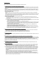
• SAFETY PRECAUTIONS •
(Always read these instructions before using this equipment.)
Before using this product, please read this manual and the relevant manuals introduced in this manual
carefully and pay full attention to safety to handle the product correctly.
The instructions given in this manual are concerned with this product only. For the safety instructions of
the programmable controller system, please read the user's manual for the CPU module to use.
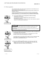
In this manual, the safety precautions are ranked as "DANGER" and "CAUTION".
DANGER
Indicates that incorrect handling may cause hazardous conditions,
resulting in death or severe injury.
! CAUTION
Indicates that incorrect handling may cause hazardous conditions,
resulting in medium or slight personal injury or physical damage.
!
Note that the ! CAUTION level may lead to a serious consequence according to the circumstances.
Always follow the instructions of both levels because they are important to personal safety.
Please store this manual in a safe place and make it accessible when required. Always forward it to the
end user.
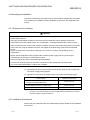
[DESIGN PRECAUTIONS]
!
DANGER
• If a communication error occurs in the AS-i system, the input will turn OFF from the slave having
the communication error.
Output to the slave having the communication error will be held or cleared depending on the
slave specifications.
The AS-i system communication error can be confirmed with the buffer memory's List of Active
Slaves (LAS) (15H to 18H) and with the input signal Configuration error (X4).
Using the above information, configure an interlock circuit on the sequence program so that the
system activates safely.
There is a risk of accidents caused by incorrect outputs or operations.
• Depending on the module fault, the input/output could enter ON or OFF status.
Provide an external monitoring circuit for I/O signals that could lead to major accidents.
!
CAUTION
• Do not bundle AS-i cable together with main circuit or power lines, or lay them close to these
lines.
As a guide, separate these lines by a distance of at least 100 mm, otherwise malfunctions may
occur due to noise.
A-1
A-1
[INSTALLATION PRECAUTIONS]
!
CAUTION
• Use the programmable controller in an environment that meets the general specifications in
CPU module User’s Manual.
Using the programmable controller in an environment outside the range of the general
specifications could result in cause electric shock, fire, erroneous operation, and damage to or
deterioration of the product.
• Do not touch conductive parts or electronic components of the module with your bare hands.
This could cause malfunction or failure of the module.
• While pressing the lever on the lower part of the module, fully insert the module fixing latch into
the hole of the base unit, snap the module into place, and tighten the module fixing screws with
the specified torque.
Failure to observe this could result in damage to the screws or module, module falling, short or
misoperation.
If the screws are tightened excessively, it may damage the screws and cause the module to
short-circuit, malfunction or fall off.
• Always shut off all phases of the programmable controller power supply and AS-i power supply
externally before mounting or removing the module.
Failure to shut off all phases could lead to product damage.
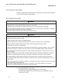
[WIRING PRECAUTIONS]
!
DANGER
• Switch off all phases of the programmable controller power supply and AS-i power supply
outside the programmable controller before starting installing or wiring work.
There is a risk of electric shock or malfunction.
[WIRING PRECAUTIONS]
!
CAUTION
• Always confirm the products terminal layout before wiring to the module.
Incorrect wiring could lead to fires or faults.
• Wiring installation screws to the specified torque.
If a wiring installation screws is not tightened to the specified torque, the module may fall out,
short circuit, or malfunction.
If a wiring installation screws is tightened excessively, exceeding the specified torque, the
module may fall out, short circuit, or malfunction due to breakage of the screw or the module.
• Make sure that no foreign matter such as chips or wire offcuts gets inside the module.
It will cause fire, failure, or malfunction.
• A label is installed at the upper part of a module to prevent the entry of foreign matters. Do not
remove the label during wiring. However, be sure to remove it for heat dissipation during
system operation.
A-2
A-2
[WIRING PRECAUTIONS]
!
CAUTION
• To connect the AS-i cable to the module, the cable must be securely fixed. Please be sure to
run it in a duct, or clamp it.
Failure to observe this could cause the unstable cable connection, resulting in damage to the
cable or module by carelessly pulling the cable, or the system malfunction due to poor cable
connection.
• When removing the AS-i cable from a module, do not pull it out by hand. Always be sure to
unscrew the module mounting screws in advance.
If the cable is pulled while being connected to the module, it could cause damage to the cable or
module, or the system malfunction due to poor cable connection.
[STARTING AND MAINTENANCE PRECAUTIONS]
!
CAUTION
• Do not touch terminals while the power is ON.
This could cause misoperations.
• Do not disassemble or modify any module.
This could cause failure, misoperation, injuries, or fire.
• When cleaning a module or retightening terminal screws, always be sure to externally switch off
all the phases of the programmable controller power supply and AS-i power supply in advance.
Failure to observe this could result in module failure or misoperation.
Loose or excessive tightening could cause damage to the module or screws, module falling,
short or misoperation.
• When mounting or removing a module, always be sure to externally switch off all the phases of
the programmable controller power supply and AS-i power supply in advance.
Failure to observe this could result in module failure or misoperation.
• Do not mount/remove the module to/from the base unit more than 50 times after the first use of the
product. (IEC 61131-2 compliant)
Failure to do so may cause malfunction.
• Always make sure to touch the grounded metal to discharge the electricity charged in the body,
etc., before touching the module.
Failure to do so may cause a failure or malfunctions of the module.
[DISPOSAL PRECAUTIONS]
!
CAUTION
• When disposing of this product, treat it as industrial waste.
A-3
A-3
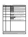
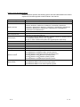
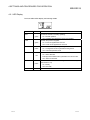
REVISIONS
The manual number is given on the bottom left of the back cover.
Print Date
Apr., 2002
Feb., 2003
Manual Number
SH (NA)-080291E-A First edition
SH (NA)-080291E-B Correction
May, 2003
SH (NA)-080291E-C
Revision
SAFETY PRECAUTIONS, Section 5.2.2, 5.4
Correction
Section 5.3.1
Jun., 2004
SH (NA)-080291E-D
Correction
Section 2.2, 3.3.2, 3.4.2, 4.4.1, 5.3.2, 5.5, 5.6, 5.7, 7.1.1, 7.1.2
Jan., 2006
SH (NA)-080291E-E
Correction
SAFETY PRECAUTIONS, Compliance with the EMC and Low
Voltage Directives, Product Structure, Chapter 1, Section 2.1, 2.2,
3.1, 3.2, 3.3, 3.4, 3.5.1, 4.3.1, Chapter 5 (screen change), Section
5.2.2, 7.1, 7.2, 8.4
Jan., 2008
SH (NA)-080291E-F
Correction
SAFETY PRECAUTIONS, Generic Terms and Abbreviations,
Section 2.1, 2.2, 2.4, 3.3.1, 3.4.2, 4.2, 4.3.1, Chapter 5, Section 7.1.1,
7.2.1, Appendix 1, Index
May, 2008
SH (NA)-080291E-G
Change of a term
"PLC" was changed to "programmable controller".
Correction
SAFETY PRECAUTIONS, Compliance with the EMC and Low
Voltage Directives, Generic Terms and Abbreviations, Section 2.1,
2.2, 4.3.1, 4.5.1 to 4.5.3, 5.2.1, 5.3.3, 5.4, 5.5, 8.1
Japanese Manual Version SH-080276-G
This manual confers no industrial property rights or any rights of any other kind, nor does it confer any patent
licenses. Mitsubishi Electric Corporation cannot be held responsible for any problems involving industrial property
rights which may occur as a result of using the contents noted in this manual.
© 2002 MITSUBISHI ELECTRIC CORPORATION
A-4
A-4
INTRODUCTION
Thank you for purchasing the MELSEC-Q Series programmable controller.
Before using the equipment, please read this manual carefully to develop full familiarity with the functions
and performance of the Q Series programmable controller you have purchased, so as to ensure correct use.
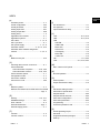
CONTENTS
SAFETY PRECAUTIONS..............................................................................................................................A- 1
REVISIONS ....................................................................................................................................................A- 4
INTRODUCTION............................................................................................................................................A- 5
CONTENTS....................................................................................................................................................A- 5
Compliance with the EMC and Low Voltage Directives................................................................................A- 8
Generic Terms and Abbreviations .................................................................................................................A- 9
Product Structure ..........................................................................................................................................A- 10
1 OVERVIEW
1- 1 to 1- 2
1.1 Features ................................................................................................................................................... 1- 2
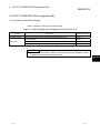
2 SYSTEM CONFIGURATION
2- 1 to 2- 7
2.1 Applicable Systems.................................................................................................................................. 22.2 How to Check the Function Version and Software Version ................................................................... 22.3 AS-i System Connection Methods........................................................................................................... 22.4 Precautions for System Configuration..................................................................................................... 23 SPECIFICATIONS
1
3
5
7
3- 1 to 3- 33
3.1 Performance Specifications ..................................................................................................................... 3- 1
3.1.1 Performance specification list ........................................................................................................... 3- 1
3.2 Functions .................................................................................................................................................. 3- 2
3.2.1 Function for communication with AS-i slaves................................................................................... 3- 2
3.2.2 Automatic refresh function by utility package................................................................................... 3- 2
3.2.3 Automatic slave address assignment function................................................................................. 3- 3
3.2.4 Parameter setting function ................................................................................................................ 3- 3
3.3 I/O Signals for CPU Module..................................................................................................................... 3- 4
3.3.1 I/O signal list ...................................................................................................................................... 3- 4
3.3.2 Details of I/O signals ......................................................................................................................... 3- 6
3.4 Buffer Memory......................................................................................................................................... 3- 12
3.4.1 Buffer Memory List ........................................................................................................................... 3- 12
3.4.2 Details of Buffer Memory ................................................................................................................. 3- 14
3.5 Command List ......................................................................................................................................... 3- 29
3.5.1 Command Buffer <Request> List .................................................................................................... 3- 29
3.5.2 Command Buffer <Result> List ....................................................................................................... 3- 33
4 SETTINGS AND PROCEDURES FOR OPERATION
4- 1 to 4- 14
4.1 Outline Procedures for Operation............................................................................................................ 4- 1
4.2 Part Names .............................................................................................................................................. 4- 2
4.2.1 LED Display....................................................................................................................................... 4- 3
A-5
A-5
4.3 Mounting and Installation......................................................................................................................... 4- 4
4.3.1 Precautions for Handling................................................................................................................... 4- 4
4.3.2 Installation Environment.................................................................................................................... 4- 4
4.4 Connection to AS-i System...................................................................................................................... 4- 5
4.4.1 Precautions for wiring........................................................................................................................ 4- 5
4.4.2 Wiring................................................................................................................................................. 4- 6
4.5 Start-Up .................................................................................................................................................... 4- 7
4.5.1 Slave registration.............................................................................................................................. 4- 10
4.5.2 Slave address assignment............................................................................................................... 4- 12
4.5.3 Slave address erasure ..................................................................................................................... 4- 13
4.5.4 Automatic slave address assignment function................................................................................ 4- 14
5 UTILITY PACKAGE (GX Configurator-AS)
5- 1 to 5- 43
5.1 Functions of the Utility Package .............................................................................................................. 5- 1
5.2 Installing and Uninstalling the Utility Package ........................................................................................ 5- 2
5.2.1 Handling precautions ........................................................................................................................ 5- 2
5.2.2 Operating environment...................................................................................................................... 5- 4
5.3 Utility Package Operation ........................................................................................................................ 5- 6
5.3.1 Common utility package operations ................................................................................................. 5- 6
5.3.2 Operation overview ........................................................................................................................... 5- 9
5.3.3 Starting the Intelligent function module utility.................................................................................. 5- 10
5.4 Auto refresh setting ................................................................................................................................. 5- 12
5.5 Monitor/Test ............................................................................................................................................ 5- 14
5.5.1 X/Y monitor/test................................................................................................................................ 5- 18
5.5.2 (A-slaves) List of Detected Slaves (LDS) ........................................................................................ 5- 19
5.5.3 (B-slaves) List of Detected Slaves (LDS) ........................................................................................ 5- 20
5.5.4 (A-slaves) List of Active Slaves (LAS) ............................................................................................. 5- 21
5.5.5 (B-slaves) List of Active Slaves (LAS) ............................................................................................. 5- 22
5.5.6 (A-slaves) List of Projected Slaves (LPS (For Read)) .................................................................... 5- 23
5.5.7 (B-slaves) List of Projected Slaves (LPS (For Read)) .................................................................... 5- 24
5.5.8 (A-slaves) List of slaves that differ from settings............................................................................. 5- 25
5.5.9 (B-slaves) List of slaves that differ from settings............................................................................. 5- 26
5.5.10 (A-slaves) Error Slave List ............................................................................................................. 5- 27
5.5.11 (B-slaves) Error Slave List ............................................................................................................. 5- 28
5.5.12 (A-slaves) List of Peripheral Faults (LPF) ..................................................................................... 5- 29
5.5.13 (B-slaves) List of Peripheral Faults (LPF) ..................................................................................... 5- 30
5.5.14 (A-slaves) Number of I/O Points.................................................................................................... 5- 31
5.5.15 (B-slaves) Number of I/O Points.................................................................................................... 5- 32
5.5.16 (A-slaves) Input Data of Slave Addr. From 1A-31A ...................................................................... 5- 33
5.5.17 (B-slaves) Input Data of Slave Addr. From 1B-31B ...................................................................... 5- 34
5.5.18 (A-slaves) Output Data of Slave Addr. From 1A-31A ................................................................... 5- 35
5.5.19 (B-slaves) Output Data of Slave Addr. From 1B-31B ................................................................... 5- 36
5.5.20 Analog Input Data (Slave Addr.1-31) ............................................................................................ 5- 37
5.5.21 Analog Output Data (Slave Addr.1-31).......................................................................................... 5- 38
5.6 Command Request / Command Result ................................................................................................. 5- 39
5.7 Configuration Data Registration/EEPROM Storage .............................................................................. 5- 41
5.7.1 Setting the Configuration Data (LPS) .............................................................................................. 5- 43
A-6
A-6
6 TRANSMISSION DELAY TIME
6- 1 to 6- 2
6.1 AS-i cycle Time ........................................................................................................................................ 6- 1
6.2 Input Transmission Delay ........................................................................................................................ 6- 2
6.3 Output Transmission Delay ..................................................................................................................... 6- 2
7 PROGRAMMING
7- 1 to 7- 8
7.1 I/O Slave................................................................................................................................................... 77.1.1 Program example when utility package is used............................................................................... 77.1.2 Program example used when utility package is not used................................................................ 77.2 Analog Slave ............................................................................................................................................ 77.2.1 Program example when utility package is used............................................................................... 77.2.2 Program example when utility package is not used......................................................................... 78 TROUBLESHOOTING
8- 1 to 8- 6
8.1 Checking Items at Error Occurrence ....................................................................................................... 88.2 Error Checking ......................................................................................................................................... 88.2.1 LED check ......................................................................................................................................... 88.3 Error Code List ......................................................................................................................................... 88.4 Checking the QJ71AS92 status using GX Developer system monitor .................................................. 8APPENDIX
1
2
4
5
6
8
1
2
2
3
4
App.- 1 to App.- 7
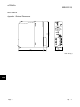
Appendix 1 External Dimensions..............................................................................................................App.- 1
Appendix 2 AS-i Protocol Implementation Conformance Statement (PICS) ..........................................App.- 2
Appendix 3 Differences between QJ71AS92 and A1SJ71AS92 ............................................................App.- 4
INDEX
A-7
Index- 1 to Index- 2
A-7
Compliance with the EMC and Low Voltage Directives
(1) For programmable controller system
To configure a system meeting the requirements of the EMC and Low Voltage
Directives when incorporating the Mitsubishi programmable controller (EMC and
Low Voltage Directives compliant) into other machinery or equipment, refer to
Chapter 9 "EMC AND LOW VOLTAGE DIRECTIVES" of the QCPU User's
Manual (Hardware Design, Maintenance and Inspection).
The CE mark, indicating compliance with the EMC and Low Voltage Directives, is
printed on the rating plate of the programmable controller.
(2) For the product
No additional measures are necessary for the compliance of this product with the
EMC and Low Voltage Directives.
A-8
A-8
Generic Terms and Abbreviations
Unless otherwise specified, the following generic terms and abbreviations are used to
explain the QJ71AS92 type AS-i master module in this manual.
Abbreviation/general terms
QJ71AS92
QCPU (Q mode)
Extension cable
GX Configurator-AS
GX Developer
Description of the abbreviation/general terms
Abbreviation of QJ71AS92.
Generic term for, Q00JCPU, Q00CPU, Q01CPU, Q02CPU, Q02HCPU, Q06HCPU,
Q12HCPU, Q25HCPU, Q02PHCPU, Q06PHCPU, Q12PHCPU, Q25PHCPU,
Q12PRHCPU, Q25PRHCPU, Q02UCPU, Q03UDCPU, Q04UDHCPU, Q06UDHCPU,
Q13UDHCPU, Q26UDHCPU, Q03UDECPU, Q04UDEHCPU, Q06UDEHCPU,
Q13UDEHCPU and Q26UDEHCPU.
Generic term for QC05B, QC06B, QC12B, QC30B, QC100B extension cable.
Generic term for QJ71AS92 type AS-i master module setting and monitor tool GX
Configurator-AS (SW1D5C-QASU-E).
Generic product name for SWnD5C-GPPW-E, SWnD5C-GPPW-EA, SWnD5C-GPPWEV, and SWnD5C-GPPW-EVA. ("n" is 4 or greater.)
"-A" and "-V" mean volume license product and upgrade product respectively.
LAS
Abbreviation for List of Active Slaves.
LDS
LPF
Abbreviation for List of Detected Slaves.
Abbreviation for List of Peripheral Faults.
LPS
Abbreviation for List of Projected Slaves.
EC flag
Abbreviation for Execution Control flag.
Windows Vista
R
Windows XP
A-9
R
Generic term for the following:
R
R
Microsoft Windows Vista Home Basic Operating System,
R
R
Microsoft Windows Vista Home Premium Operating System,
R
R
Microsoft Windows Vista Business Operating System,
R
R
Microsoft Windows Vista Ultimate Operating System,
R
R
Microsoft Windows Vista Enterprise Operating System
Generic term for the following:
R
R
Microsoft Windows XP Professional Operating System,
R
R
Microsoft Windows XP Home Edition Operating System
A-9
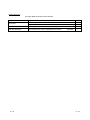
Product Structure
The follow table shows the product stricture.
Type
QJ71AS92
Product
Quantity
QJ71AS92 type AS-i master module
1
Connector
1
SW1D5C-QASU-E
GX Configurator-AS Version1 (1-license product)
(CD-ROM)
1
SW1D5C-QASU-EA
GX Configurator-AS Version1 (Multiple-license product)
(CD-ROM)
1
A - 10
A - 10
1 OVERVIEW
MELSEC-Q
1 OVERVIEW
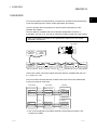
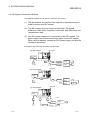
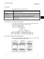
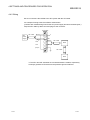
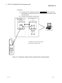
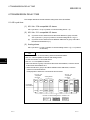
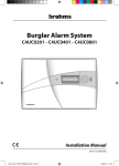
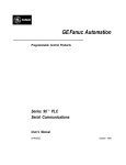
This manual explains the specifications, procedures for operation and troubleshooting
of the QJ71AS92 type AS-i master module (hereinafter, QJ71AS92).
The AS-i (Actuator-Sensor-Interface) is a network system specified by the IEC
standard: IEC 62026-2.
The QJ71AS92 is compatible with the AS-Interface Specification Version 2.11
(hereinafter, AS-i Ver.2.11), and can be used as the master module of the AS-i system.
Refer to IEC 62026-2 for details on the specifications related to the AS-i system
described in this manual.
QJ71AS92
MELSEC
POWER
Q25HCP
U
QJ71C2 4
MODE
RUN
CH2.
CH1.
ERR.
CH1.
USER
BAT.
BOOT
RS-232
AS-i Slave
Ver.2.04 Slave
address 6
AS-i Slave
address 1A
Analog Slave
Slave
address 5
AS-i Slave
address 2A
CH.2
SDA
1
SG
PULL
SDB
USB
2
(FG)
RDA
3
4
(FG)
RS-232
RDB
RS-422
/ 485
MITSUBISHI
AS-i Slave
address 4A
Group A
AS-i
power
supply
5
6
7
AS-i Slave
address 1B
AS-i Slave
address 4B
Group B
Use the AS-i cables, AS-i power supply and slaves that are compatible with AS-i Ver.
2.11 or AS-i Ver. 2.04.
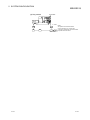
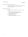
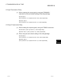
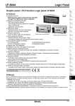
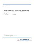
The CPU module communicates the I/O data of the slaves via the QJ71AS92 buffer
memory according to instructions.
CPU module
QJ71AS92
I/O Slave
Buffer memory
Communication
memory
Transmission
data
Output data
Output data
Receive data
Input data
Input data
Device memory
Instruction *1
Analog Slave
Communication
memory
Instruction *1
Transmission
data
Output data
Output data
Receive data
Input data
Input data
*1: Use of GX Configurator-AS enables automatic refresh without programs. See
Chapter 5 for details.
1-1
1-1
1
1 OVERVIEW
MELSEC-Q
1.1 Features
1
The QJ71AS92 has the following features.
(1) Maximum number of connected slaves
As the AS-i master, the QJ71AS92 can control a maximum of 62 slaves by
splitting the slave addresses into two groups (A and B).
(2) Communication with analog slaves
Provided that one channel is equal to 16 bits, the QJ71AS92 can communicate
with AS-i analog input or output slaves of one to four channels.
(3) Overall distance
The overall distance is 100m.
Note that the overall distance can be extended to up to 300m by using two
repeaters.
(4) Automatic slave address assignment function (Automatic address
assignment function)
The QJ71AS92 can automatically assign the same address to the new slave
(same type of product), whose slave address is 0, when changing a slave.
(5) Easy setting by using utility package (Sold separately)
GX Configurator-AS is available as an utility package (Sold separately).
Although not necessarily required, GX Configurator-AS enables the automatic
refresh to be set from within the software, resulting in easy sequence
programming, slave address setting, and monitoring of the setting and operation
statuses.
1-2
1-2
2 SYSTEM CONFIGURATION
MELSEC-Q
2 SYSTEM CONFIGURATION
This chapter explains the system configuration of the QJ71AS92.
2.1 Applicable Systems
This section describes the applicable systems.
2
(1) Applicable modules and base units, and No. of modules
(a) When mounted with a CPU module
The table below shows the CPU modules and base units applicable to the
QJ71AS92 and quantities for each CPU model.
Depending on the combination with other modules or the number of
mounted modules, power supply capacity may be insufficient.
Pay attention to the power supply capacity before mounting modules, and if
the power supply capacity is insufficient, change the combination of the
modules.
Applicable CPU module
CPU type
Basic model
QCPU
*1
CPU model
Q00JCPU
Q00CPU
Q01CPU
No. of modules
*2
Base unit
Main base unit
Extension base unit
Up to 8
Up to 24
Q02CPU
High
Performance
model QCPU
Q02HCPU
Q06HCPU
Up to 64
Q12HCPU
Q25HCPU
Q02PHCPU
Process CPU
Q06PHCPU
Q12PHCPU
Up to 64
Q25PHCPU
Programmable
controller CPU
Redundant CPU
Q12PRHCPU
Q25PRHCPU
Q02UCPU
Up to 53
Up to 36
Q03UDCPU
Q04UDHCPU
Q06UDHCPU
Universal model
QCPU
Q13UDHCPU
Q26UDHCPU
Q03UDECPU
Up to 64
Q04UDEHCPU
Q06UDEHCPU
Q13UDEHCPU
Q26UDEHCPU
Safety CPU
C Controller module
QS001CPU
Q06CCPU-V
Q06CCPU-V-B
N/A
Up to 64
: Applicable,
2-1
: N/A
2-1
2 SYSTEM CONFIGURATION
MELSEC-Q
*1: Limited within the range of I/O points for the CPU module.
*2: Can be installed to any I/O slot of a base unit.
(b) Mounting to a MELSECNET/H remote I/O station
The QJ71AS92 cannot be mounted to any MELSECNET/H remote I/O
station.
Mount it to a CPU module on a master station.
2
(2) Support of the multiple CPU system
When using the QJ71AS92 in a multiple CPU system, refer to the QPU User's
Manual (Multiple CPU System) first.
(a)
Compatible QJ71AS92
The function version of the first released QJ71AS92 is B, and it supports
multiple CPU systems.
(b)
Intelligent function module parameters
Write intelligent function module parameters to only the control CPU of the
QJ71AS92.
(3) Supported software packages
Relation between the system containing the QJ71AS92 and software package is
shown in the following table.
GX Developer is necessary when using the QJ71AS92.
Q00J/Q00/Q01CPU
Q02/Q02H/Q06H/
Q12H/Q25HCPU
Q02PH/Q06PHCPU
Q12PH/Q25PHCPU
Q12PRH/
Q25PRHCPU
Q02U/Q03UD/
Q04UDH/
Q06UDHCPU
Q13UDH/
Q26UDHCPU
Q03UDE/Q04UDEH/
Q06UDEH/Q13UDEH
/Q26UDEHCPU
2-2
Single CPU system
Multiple CPU system
Single CPU system
Multiple CPU system
Single CPU system
Multiple CPU system
Single CPU system
Multiple CPU system
Redundant system
Single CPU system
Multiple CPU system
Single CPU system
Multiple CPU system
Single CPU system
Multiple CPU system
Software version
GX Developer
GX Configurator-AS
Version 7 or later
Version 8 or later
Version 4 or later
Version 6 or later
Version 1.13P or later
Version 8.68W
or later
Version 7.10L or later
Version 8.45X or later
Version 1.16S or later
Version 8.48A or later
Version 8.62Q or later Version 1.21X or later
Version 8.68W
or later
2-2
2 SYSTEM CONFIGURATION
MELSEC-Q
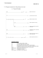
2.2 How to Check the Function Version and Software Version
This section describes how to check the function version of the QJ71AS92 and the GX
Configuration-AS software version.
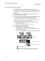
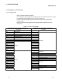
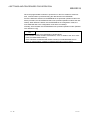
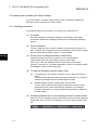
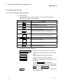
(1) Checking the function version of the QJ71AS92
(a) Checking at "the SERIAL field of the rating plate" located on the side of the
module
The serial No. and function version of the module is shown in the SERIAL
field of the rating plate.
Serial No. (Upper 5 digits)
Function version
Relevant regulation standards
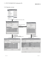
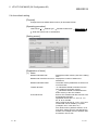
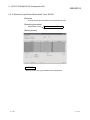
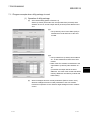
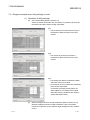
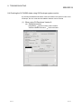
(b) Checking by GX Developer
The serial No. and function version of the module are displayed on the
"Production Info. List" and "Module’s Detailed Information" screens of GX
Developer.
The following explains how to check them on the "Production Info. List"
screen. (For the case of "Module’s Detailed Information", refer to Section
8.4.)
[Operating procedure]
[Diagnostics]
[System monitor]
Product Inf. List
[Serial No., Ver., Product No.]
• Serial No. of the module is displayed in the Serial No. column.
• Function version of the module is displayed in the Ver. column.
• Serial No. printed on the rating plate is displayed in the Production No.
*1
column.
Note that, because the QJ71AS92 does not support the production No.
display, "-" is displayed.
*1: The Production No. column display is active only when the CPU used is
a Universal model QCPU.
2-3
2-3
2 SYSTEM CONFIGURATION
MELSEC-Q
POINT
The serial No. on the rating plate may be different from the serial No. displayed on
the product information screen of GX Developer.
• The serial No. on the rating plate indicates the management information of the
product.
• The serial No. displayed on the product information screen of GX Developer
indicates the function information of the product.
The function information of the product is updated when a new function is
added.
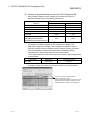
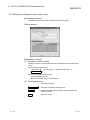
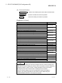
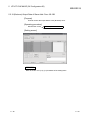
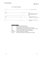
(2) Checking the software version of GX Configurator-AS
The software version of GX Configurator-AS can be checked in GX Developer’s
"Product information" screen.
[Operating procedure]
GX Developer
[Help]
[Product information]
Software version
(In the case of GX Developer Version 8)
2-4
2-4
2 SYSTEM CONFIGURATION
MELSEC-Q
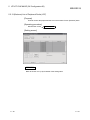
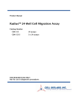
2.3 AS-i System Connection Methods
The following methods can be used to connect the AS-i system.
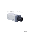
(1) The star method, line method, tree method or ring method can be
used to connect the AS-i system.
(2) The AS-i system does not require a terminator. The overall
distance is 100m when a repeater is not used, and 300m when two
repeaters are used.
(3) One AS-i power supply unit is connected to the AS-i system. The
power supply can be connected at any place on the AS-i system.
When using a repeater, connect an AS-i power supply unit after the
repeater is connected.
Examples of the connection method are shown below.
QJ71AS92
(a) Star method
QJ71C24
Q25HCP
POWER U
MODE
MELSEC
CH1.
RUN
CH2.
ERR.
CH1.
USER
BAT.
BOOT
RS-232
AS-i power
supply
CH.2
S DA
1
SG
PULL
2
SDB
USB
(FG)
3
RDA
4
(FG)
RS-232
5
RDB
6
RS-422
/485
MITSUBISHI
7
S
S
S
S
S : slave
Repeater
AS-i power
supply
S
Repeater
AS-i power
supply
S
Repeater
AS-i power
supply
S
QJ71AS92
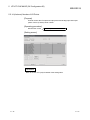
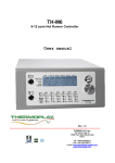
(b) Line method
MELSEC
POWER
Q25HCP
U
QJ7 1C24
MODE
RUN
CH1.
CH2.
E RR.
CH1.
USER
BAT.
BOOT
RS -232
AS-i power
supply
CH.2
S DA
1
SG
PULL
USB
2
SDB
(FG)
3
RDA
4
(FG)
RS-232
5
RDB
6
RS-422
/ 485
MITSUBISHI
7
S
S
S
S
AS-i power
supply
AS-i power
supply
S
S : slave
Repeater
QJ71AS92
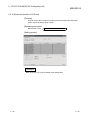
(c) Tree method
MELSEC
POWER
Q25HCP
U
QJ71C2 4
MODE
RUN
CH2.
CH1.
ERR.
CH1.
USE R
BAT.
BOOT
RS-232
AS-i power
supply
CH.2
SDA
1
SG
PULL
USB
2
SDB
(FG)
3
RDA
4
(FG)
RS-232
MITSUBISHI
5
RDB
6
RS-422
/ 485
7
S : slave
S
S
S
S
Repeater
S
2-5
Repeater
AS-i power
supply
S
2-5
2 SYSTEM CONFIGURATION
MELSEC-Q
QJ71AS92
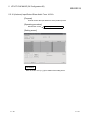
(d) Ring method
MELSEC
POWER
Q25HCP
U
QJ71C2 4
MODE
RUN
CH1.
ERR.
CH2.
CH1.
USER
BAT.
BOOT
RS-232
AS-i power
supply
CH.2
SDA
PULL
1
SG
USB
SDB
2
(FG)
RDA
3
4
(FG)
RS-232
MITSUBISHI
RDB
RS-422
/ 485
5
6
7
S : slave
S
S
S
2-6
S
S
S
(Note)
The system cannot be branched to
a tree connection, etc., from the ring
connection. Apartial loop cannot be formed.
A repeater cannot be used.
2-6
2 SYSTEM CONFIGURATION
MELSEC-Q
2.4 Precautions for System Configuration
(1) The QJ71AS92 can be mounted in any slot of the base unit.
If the QJ71AS92 is mounted on an extension base unit (Q52B, Q55B) to which
the power supply module cannot be mounted, the power supply capacity may be
insufficient.
(2) The QJ71AS92 cannot be mounted on a remote I/O station in a
MELSECNET/H network system.
(3) The QJ71AS92 can use the slave addresses assigned to AS-i Ver.
1
2.11-compatible slaves by grouping them into A and B. *
2
The other slaves * than the AS-i Ver. 2.11-compatible I/O slaves cannot be
grouped into A and B because of the AS-i specifications. Assign them to the
slave addresses other than those used for group A and B.
*1: Check whether the slaves can be grouped or not by reference to the
manuals of the slaves used.
*2: Analog slave, AS-i Ver. 2.04-compatible I/O slave, etc.
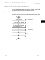
(4) For Use with Q12PRH/Q25PRHCPU
(a) GX Configurator-AS connection
GX Configurator-AS cannot be used when accessing the
Q12PRH/Q25PRHCPU via an intelligent function module on an extension
base unit from GX Developer.
Connect a personal computer with a communication path indicated below.
1
2
Main base unit
Extension base unit
(GX Configurator-AS cannot be used.)
2-7
1
Direct connection to the CPU
2
Connection through an intelligent function module on the main base unit
(Through Ethernet module, MELSECNET/H module, or CC-Link module)
2-7
3 SPECIFICATIONS
MELSEC-Q
3 SPECIFICATIONS
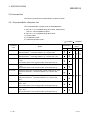
3.1 Performance Specifications
The following are the performance specifications of the QJ71AS92.
3.1.1 Performance specification list
Item
Specifications
Max. number of AS-i slaves *1
3
62 (Group A: 31, Group B: 31)
Max. number of I/O points *2
(1 point = 1 bit)
Input
248 points
Output
248 points
Max. address of analog I/O points
(1 point = 16 bits)
Input
124 points
Output
124 points
Approx. 5ms (without I/O slave grouping)
Approx. 10ms (with I/O slave grouping)
Approx. 35ms (per analog slave channel)
I/O refresh time
Communication speed
167kbps
Transmission distance
Max. 100m (max. 300m with two repeaters)
Connection type
Bus network type (star, line, tree and ring)
Communication method
APM modulation method (Alternating Pulse Modulation)
Error control method
Parity check
Internal memory
EEPROM (for parameter registration), number of writes: 100,000 times
Number of occupied I/O points
32 points (I/O assignment: 32 intelligent points)
Cable type
Use dedicated AS-i cable.
External supply power
Voltage
TYP. 30.5VDC (supplied by AS-i power supply)
Current consumption 46mA (TYP 30.5VDC)
5VDC internal current consumption
0.40A
Weight
0.12kg
*1: This is the max. number of Ver. 2.11-compatible I/O slave stations (can be grouped) configured in the same system. If
Ver.2.11-compatible I/O slaves that cannot be grouped, analog slaves, and Ver. 2.04-compatible I/O slaves are used
together in the same system, calculate the max. number of slaves using the following expression.
(NIO-A +NIO-B)+2 (NA+NIO)< 62 (Group A 31, Group B 31)
Number of Group A Ver. 2.11-compatible I/O slaves: NIO-A Number of Group B Ver. 2.11-compatible I/O slaves: NIO-B
Number of Ver. 2.04-compatible I/O slaves: NIO
Number of Ver. 2.11-compatible analog slaves: NA
Slave Type
AS-I Ver. 2.11-compatible I/O slave
AS-I Ver. 2.04-compatible I/O slave
AS-I Ver. 2.11-compatible analog slave
Grouping
Please confirm with the manufacturer of the I/O slave unit whether the unit
can be grouped.
Disabled
*2: One slave uses four inputs and four outputs.
One analog slave also uses four inputs and four outputs.
For the noise immunity, withstand voltage, insulation resistance and others in the programmable controller system using
this module, Refer to the power supply module specifications given in the used CPU module User’s Manual.
For the general specifications of the QJ71AS92, Refer to the User's Manual of the used CPU module.
3-1
3-1
3 SPECIFICATIONS
MELSEC-Q
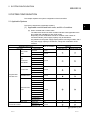
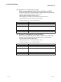
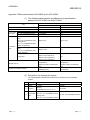
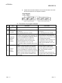
3.2 Functions
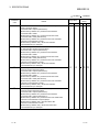
The following table lists the QJ71AS92 functions.
Item
AS-i slave communication
function
Automatic refresh function by
utility package
Automatic slave address
assignment function
Parameter setting function
Description
Communicates with AS-i slaves.
Automatically refreshes the Q71AS92’s I/O data to the CPU module’s device memory.
When a slave is replaced with a new one of the same model, this function automatically
assigns the previous slave address to the new one that has slave address 0.
Sets slave addresses and QJ71AS92’s parameters by the following:
• Utility package
• CODE LED and switches on the module’s front face.
• Sequence program
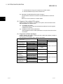
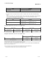
3.2.1 Function for communication with AS-i slaves
The QJ71AS92 complies with AS-i Ver. 2.11 and can communicate with AS-i slaves.
The QJ71AS92 can be connected with the following slaves.
• AS-i Ver. 2.11-compatible I/O slave
• AS-i Ver. 2.04-compatible I/O slave
• AS-i Ver. 2.11-compatible analog slave
QJ71AS92
Communication
AS-i power
supply
AS-iVer.2.11
-compatible
I/O slave
AS-iVer.2.04
-compatible
I/O slave
AS-iVer.2.11
-compatible
Analog slave
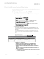
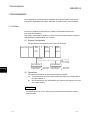
3.2.2 Automatic refresh function by utility package
The Q71AS92’s I/O data can be automatically refreshed to the CPU module’s device
memory using utility package (GX Configurator-AS).
I/O Slave
CPU module
QJ71AS92
Device memory
Buffer memory
Communication
memory
Transmission
data
Output data
Output data
Receive data
Input data
Input data
Analog Slave
Communication
memory
Transmission
data
Output data
Output data
Receive data
Input data
Input data
Automatic refresh at END processing of CPU module
3-2
3-2
3
3 SPECIFICATIONS
MELSEC-Q
3.2.3 Automatic slave address assignment function
This function automatically sets the slave address of the old slave to the new slave of
the same product having slave No. 0 at the time of slave replacement.
Refer to Section 4.5.4 for details.
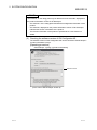
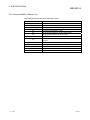
3.2.4 Parameter setting function
Slave addresses and QJ71AS92’s parameters can be set by any of the following
methods.
(1) Using the utility package (GX Configurator-AS)
(Refer to "Chapter 5 UTILITY PACKAGE (GX Configurator-AS)".)
(2) Using the CODE LED and switches
(Refer to "Section 4.5 Start-Up".)
(3) Using the sequence program
(Refer to "Section 3.4.2 (15) Command buffer <request>".)
3-3
3-3
3 SPECIFICATIONS
MELSEC-Q
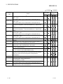
3.3 I/O Signals for CPU Module
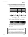
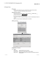
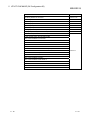
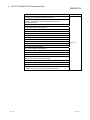
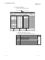
3.3.1 I/O signal list
Table 3.3 lists QJ71AS92 I/O signals.
The following I/O signal assignment is based on the case where the start I/O No. of the
QJ71AS92 is "0000" (installed to slot 0 of the main base unit).
Device X represents an input signal from the QJ71AS92 to the programmable
controller CPU.
Device Y shows an output signal from the programmable controller CPU to the
QJ71AS92.
Table 3.3 List of I/O signals
Signal Direction: programmable controller CPU
QJ71AS92
Input Signal
Signal name
X0
Module Ready
X1
Not used
X2
Command Completion
X3
Configuration Register Completion
X4
Configuration Error
X5
AS-i Power Fail
X6
Normal Operation Active
X7
Configuration Mode Active
X8
X9
XA
XB
Not used
XC
XD
XE
XF
X10
X11
X12
X13
X14
X15
X16
X17
Not used
X18
X19
X1A
X1B
X1C
X1D
X1E
X1F
3-4
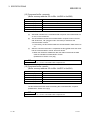
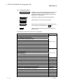
Signal Direction: programmable controller CPU
QJ71AS92
Output Signal
Signal name
Y0
Y1
Y2
Y3
Y4
Y5
Y6
Y7
Not used
Y8
Y9
YA
YB
YC
YD
YE
YF
Y10
Not used
Y11
Y12
Command Execution Request
Y13
Configuration Register Request
Y14
Off-line Phase
Y15
Auto Address Assignment Function
Y16
Configuration Mode
Y17
Protected Operation Mode
Y18
Y19
Not used
Y1A
Y1B
Y1C
EEPROM Write
Y1D
Refresh Instruction
Y1E
Not used
Y1F
3-4
3 SPECIFICATIONS
MELSEC-Q
TIP
The signals indicated as "Not used" in Table 3.3 are used by the system and cannot
be used by the user.
If they are turned ON/OFF by the sequence program, correct operation of the
module cannot be guaranteed.
3-5
3-5
3 SPECIFICATIONS
MELSEC-Q
3.3.2 Details of I/O signals
This section describes the details of the QJ71AS92 I/O signals.
(1) X0: Module Ready
X0 turns ON when the QJ71AS92 enters the operation enabled status after the
power is turned ON or the CPU module is reset.
X0 turns OFF when a hardware fault occurs.
OFF : Operation disabled
ON : Operation enabled
ON
X0
OFF
Not yet ready to operate
Ready to operate
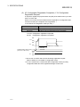
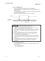
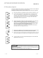
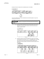
(2) X2: Command Completion, Y12: Command Execution Request
A request to execute the command specified for Command Buffer Request of the
buffer memory is made when Y12 turns ON. The command requested when Y12
1
turned ON is executed, and X2 turns ON at completion of that command. *
(Refer to Section 3.4.2)
Y12 ON : Command requested
X2 ON : Command completed
ON
Y12
X2
OFF
ON
OFF
Command
execution
Command Completion
(55H to 59H)
Command Result
(25H to 29H)
Command completion
Request
Result
*1: Do not turn Y12 OFF until X2 turns ON during command execution.
3-6
3-6
3 SPECIFICATIONS
MELSEC-Q
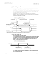
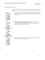
(3) X3: Configuration Registration Completion, Y13: Configuration
Registration Request
A request to register the projected slave list (LPS) of the buffer memory is made
when Y13 turns ON.
When Y13 turns ON, the QJ71AS92 executes registration of configuration data,
1
and X3 turns ON upon completion of the registration. *
2
Y13 is valid in the configuration mode (X7: ON). *
Buffer memory address
Details
49H to 4AH
(A-slaves) List of Projected Slaves (LPS (For Write))
4BH to 4CH
(B-slaves) List of Projected Slaves (LPS (For Write))
Y13 ON : Configuration registration requested
X3 ON : Configuration registration completed
ON
Y13
X3
OFF
ON
OFF
Registration
execution
Projected Slave List (for write)
(49H to 4AH, 4BH to 4CH)
X7
Registration completion
Slave list
ON
OFF
*1: Do not turn Y13 OFF until X3 turns ON during registration request.
Refer to Section 4.5 for details of configuration mode.
*2: If Y13 is turned ON in a mode other than configuration mode (X7: OFF),
configuration data will not be registered although X3 turns ON.
3-7
3-7
3 SPECIFICATIONS
MELSEC-Q
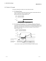
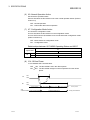
(4) X4: Configuration Error
X4 checks for a configuration error.
A configuration error occurs if the projected slave list (LPS) and detected slave
list (LDS) are different in the configuration contents.
On detection of a configuration error in the AS-i system, the QJ71AS92 turns ON
the corresponding bit of the slave list (addresses: 1DH to 20H) that differs from
the buffer memory settings and turns X4 ON.
X4 automatically turns OFF when the configuration error is all resolved.
When X4 is ON, check whether the projected slave list (LPS) is the same as the
detected slave list (LDS), for example.
OFF : No configuration error
ON : Configuration error detected
No configuration
error
Configuration error occurred
(During slave disconnection)
Configuration error
detection
Slave list that differs
from settings
(1DH to 20H)
X4
No configuration
error
Restoration from
configuration error
Bit of corresponding slave number turns ON
0
0
ON
OFF
ON
Input data of
normally ON input*1
OFF
*1: Shows the timing with the input data when the normally-ON input slave is disconnected.
(5) X5: AS-i Power Fail
X5 checks the AS-i power supply status.
The QJ71AS92 turns X5 ON when the voltage supplied by the AS-i power supply
is insufficient. It turns OFF automatically when the supplied voltage is restored.
When X5 is ON, check the rated current value of the AS-i power supply, the
wiring, and the overall distance of the system.
OFF : AS-i power supply normal
ON : AS-i power supply abnormal
X5
ON
OFF
AS-i power supply normal
AS-i power supply abnormal
AS-i power supply
fault detection
AS-i power supply normal
AS-i power supply
restoration detection
For details of the AS-i power supply specifications, contact the manufacture of
the AS-i power supply used.
3-8
3-8
3 SPECIFICATIONS
MELSEC-Q
(6) X6: Normal Operation Active
X6 checks the operation status.
X6 turns ON when the QJ71AS92 is not in the normal operation status. (Refer to
section 4.5)
OFF : Normal operation
ON : Phase other than normal operation
(7) X7: Configuration Mode Active
X7 checks the configuration mode.
X7 turns ON when the QJ71AS92 is in the configuration mode.
X7 turns OFF when the QJ71AS92 is in the mode other than configuration mode.
(Refer to section 4.5)
OFF : Mode other than configuration mode
ON : Configuration mode
Relationships between QJ71AS92 Operating Status and X6/X7
X7
Signal name
X6
ON
OFF
ON
Off-line Phase, Detection Phase, Activation Phase
OFF
Configuration mode
Protected operation mode
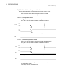
(8) Y14: Off-line Phase
Y14 is initialises AS-i communication.
OFF ON: The QJ71AS92 is set in the off-line phase.
ON OFF: The QJ71AS92 changes to normal operation from the off-line
phase.
Y14
ON
OFF
X6
ON
OFF
Normal operation
AS-i
communication During communication
3-9
Off-line Phase
Detection phase
Communication stop
Activation phase
Normal operation
During communication
3-9
3 SPECIFICATIONS
MELSEC-Q
(9) Y15: Auto Address Assignment Function
Sets the automatic slave address assignment function valid or invalid.
OFF : Automatic slave address assignment function is valid
ON : Automatic slave address assignment function is invalid
(10) Y16: Configuration Mode
OFF ON: The QJ71AS92 is set in the configuration mode.
ON OFF: The QJ71AS92 operation mode does not change.
Y16
X7
ON
OFF
ON
OFF
Protected opration mode
X6
Configuration mode
ON
OFF
(11) Y17: Protected Operation Mode
1
OFF ON: The QJ71AS92 is set in the protected operation mode. *
ON OFF: The QJ71AS92 operation mode does not change.
ON
Y17
OFF
ON
X7
OFF
Configuration mode
Protected opration mode
ON
X6
OFF
*1: When the QJ71AS92 has recognized the slave address 0, it cannot terminate
the configuration mode.
In this case, note that X7 remains ON.
3 - 10
3 - 10
3 SPECIFICATIONS
MELSEC-Q
(12) Y1C: EEPROM write
Turning Y1C ON writes the configuration data to the EEPROM.
"Write to EEPROM" can be operated in either the protected operation mode or
configuration mode.
From the next time on, the QJ71AS92 will start in the operation mode used when
write to EEPROM was performed.
After write is completed, the phase remains in normal operation.
Y1C
ON
OFF
EEPROM write
status (C6H)
0
1
Not yet executed
During write
2,3
Write completion
2: Normal completion
3: Abnormal completion
0
Not yet executed
TIP
(1) The address of writes to the EEPROM is 100,000 times.
If the address of writes exceeds 100,000 times, the error code "F70H" is
written to the QJ71AS92 buffer memory (address: C0H).
This means that the hardware is faulty. Please consult your local Mitsubishi
serves center or representative, explaining a detailed description of the
problem.
(2) If write to EEPROM is executed 1000 or more times during continuous
operation of the CPU module, the error code "F74H " is written to the
QJ71AS92 buffer memory (address: C0H).
If "F74H" is written, examine the sequence program again, make sure that
write processing has not been performed many times, and restart the CPU
module.
(3) The configuration data written to the EEPROM are the operation mode,
protected slave list (LPS), permanent configuration and permanent
parameters.
(13) Y1D: Refresh instruction
Y1D determines whether the contents of the "data output to slaves" in buffer
memory are valid.
OFF : Not output to slaves
ON : Output to slaves
3 - 11
3 - 11
3 SPECIFICATIONS
MELSEC-Q
3.4 Buffer Memory
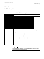
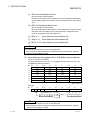
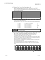
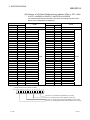
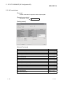
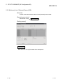
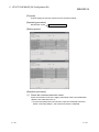
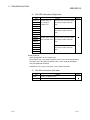
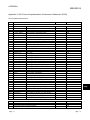
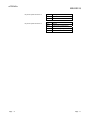
3.4.1 Buffer Memory List
Table 3.4 lists the QJ71AS92 buffer memories.
Table 3.4 Buffer memory list
Address
Details
Hexadecimal
Decimal
0H
0
(A-slaves) Input Data From Slave Address 1A-3A and part of EC Flag
1H
1
(A-slaves) Input Data From Slave Address 4A-7A
2H
2
(A-slaves) Input Data From Slave Address 8A-11A
3H
3
(A-slaves) Input Data From Slave Address 12A-15A
4H
4
(A-slaves) Input Data From Slave Address 16A-19A
5H
5
(A-slaves) Input Data From Slave Address 20A-23A
6H
6
(A-slaves) Input Data From Slave Address 24A-27A
7H
7
(A-slaves) Input Data From Slave Address 28A-31A
8H
8
(B-slaves) Input Data From Slave Address 1B-3B
9H
9
(B-slaves) Input Data From Slave Address 4B-7B
AH
10
(B-slaves) Input Data From Slave Address 8B-11B
BH
11
(B-slaves) Input Data From Slave Address 12B-15B
CH
12
(B-slaves) Input Data From Slave Address 16B-19B
DH
13
(B-slaves) Input Data From Slave Address 20B-23B
EH
14
(B-slaves) Input Data From Slave Address 24B-27B
FH
15
(B-slaves) Input Data From Slave Address 28B-31B
10H
16
EC Flags
11H to 12H
17 to 18
(A-slaves) List of Detected Slaves (LDS)
13H to 14H
19 to 20
(B-slaves) List of Detected Slaves (LDS)
15H to 16H
21 to 22
(A-slaves) List of Active Slaves (LAS)
17H to 18H
23 to 24
(B-slaves) List of Active Slaves (LAS)
19H to 1AH
25 to 26
(A-slaves) List of Projected Slaves (LPS (For Read))
1BH to 1CH
27 to 28
(B-slaves) List of Projected Slaves (LPS (For Read))
1DH to 1EH
29 to 30
(A-slaves) List of slaves that differ from settings
1FH to 20H
31 to 32
(B-slaves) List of slaves that differ from settings
21H to 22H
33 to 34
(A-slaves) Error Slave List
23H to 24H
35 to 36
(B-slaves) Error Slave List
25H to 29H
37 to 41
Command Buffer <Result>
2AH to 2FH
42 to 47
Not used
Read/write from
CPU module
Reading enabled
TIP
The slaves other than the AS-i Ver. 2.11-compatible I/O slaves assigned to group B
use the buffer memory addresses of group A.
3 - 12
3 - 12
3 SPECIFICATIONS
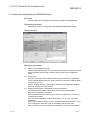
MELSEC-Q
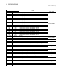
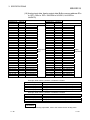
Address
Details
Hexadecimal
Decimal
30H
48
31H
49
(A-slaves) Output Data To Slave Address 4A-7A
32H
50
(A-slaves) Output Data To Slave Address 8A-11A
33H
51
(A-slaves) Output Data To Slave Address 12A-15A
34H
52
(A-slaves) Output Data To Slave Address 16A-19A
35H
53
(A-slaves) Output Data To Slave Address 20A-23A
36H
54
(A-slaves) Output Data To Slave Address 24A-27A
37H
55
(A-slaves) Output Data To Slave Address 28A-31A
38H
56
(B-slaves) Output Data To Slave Address 1B-3B
39H
57
(B-slaves) Output Data To Slave Address 4B-7B
3AH
58
(B-slaves) Output Data To Slave Address 8B-11B
3BH
59
(B-slaves) Output Data To Slave Address 12B-15B
3CH
60
(B-slaves) Output Data To Slave Address 16B-19B
3DH
61
(B-slaves) Output Data To Slave Address 20B-23B
3EH
62
(B-slaves) Output Data To Slave Address 24B-27B
3FH
63
(B-slaves) Output Data To Slave Address 28B-31B
(A-slaves) Output Data To Slave Address 1A-3A
40H to 48H
64 to 72
Not used
49H to 4AH
73 to 74
(A-slaves) List of Projected Slaves (LPS (For Write))
4BH to 4CH
75 to 76
(B-slaves) List of Projected Slaves (LPS (For Write))
4DH to 54H
77 to 84
Not used
55H
85
56H to 59H
86 to 89
Command Buffer: <Request (data word 0 to 3(Command))>
5AH to BFH
90 to 191
Not used
C0H to C5H
192 to 197 Current Error Code, Error Code History 1-5
C6H
198
Read/write from
CPU module
Command Buffer: <Request (Command)>
EEPROM Write Status
C7H to CFH
199 to 207 Not used
D0H to D1H
208 to 209 (A-slaves) List of Peripheral Faults (LPF)
D2H to D3H
210 to 211 (B-slaves) List of Peripheral Faults (LPF)
D4H to DFH
212 to 223 Not used
E0H to 15FH
224 to 351 Analog Input Data (Slave Address 1-31)
160H to 1DFH
352 to 479 Analog Output Data (Slave Address 1-31)
1E0H to 1FFH
480 to 511 (A-slaves) Number of I/O Points
200H to 21FH
512 to 543 (B-slaves) Number of I/O Points
220H to 2FFH
544 to 767 Not used
300H to 36DH
768 to 877 Extended Command Buffer <Result>
Writing enabled
Writing enabled
Writing enabled
Reading enabled
Reading enabled
Reading enabled
Reading enabled
36EH to 3FFH 878 to 1023 Not used
400H to 46DH 1024 to 1133 Extended Command Buffer <Request(Data)>
Writing enabled
46EH to 7FFH 1134 to 2047 Not used
3 - 13
3 - 13
3 SPECIFICATIONS
MELSEC-Q
3.4.2 Details of Buffer Memory
This section describes the details of each item in the buffer memory, shown in Table
3.4 of section 3.4.1.
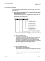
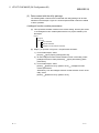
(1) Input data from slave address 1A to 3A, and some EC flags (Buffer
memory address 0H: Un\G0)
The input data from the AS-i Ver. 2.11-compatible (Group A) and AS-i Ver. 2.04compatible I/O slaves and part of the EC flag of the QJ71AS92 are stored.
Example: Buffer memory address Un\G0
Bit 15 14 13 12 11 10 9 8 7 6 5 4 3 2 1 0
Bit 0: Configuration Error
0: No configuration error
1: Configuration error occurs
Bit 1: AS-i Power Fail (APF)
0: AS-i Power On (APO)
1: AS-i Power Fail (APF)
Bit 2: Normal Operation Active
0: Normal operation
1: Not normal operation
Bit 3: Configuration Mode Active
0: Not configuration mode
1: Configuration mode
Bit 4 to 7 : Input data from slave address 1A
Bit 8 to 11 : Input data from slave address 2A
Bit 12 to 15 : Input data from slave address 3A
0: OFF
1: ON
(a) Bit 0: Configuration Error
Bit 0 checks for a configuration error.
A configuration error occurs if the projected slave list (LPS (for read)) and
detected slave list (LDS) are different in the configuration contents.
On detection of a configuration error in the AS-i system, the QJ71AS92
turns ON the corresponding bit of the slave list (addresses: 1DH to 20H) that
differs from the buffer memory settings and turns bit 0 ON.
Bit 0 automatically turns OFF when the configuration error is all resolved.
When bit 0 is ON, check whether the wiring is proper and the projected
slave list (LPS (for read)) is the same as the detected slave list (LDS), for
example. (This bit corresponds to the input signal X4.)
(b) Bit 1: AS-i Power Fail (APF)
Bit 1 checks the AS-i power supply status.
The QJ71AS92 turns bit 1 ON when the voltage supplied by the AS-i power
supply is insufficient. It turns OFF automatically when the supplied voltage
is restored.
When bit 1 is ON, check the rated current value of the AS-i power supply,
the wiring, and the overall distance of the system. (This bit corresponds to
the input signal X5.)
3 - 14
3 - 14
3 SPECIFICATIONS
MELSEC-Q
(c) Bit 2: Normal Operation Active
Bit 2 checks the operating status.
Bit 2 turns OFF when the QJ71AS92 is in the normal operation status after
module ready (X0) has turned ON. (This bit corresponds to the input signal
X6.)
(d) Bit 3: Configuration Mode Active
Bit 3 checks the operation mode.
Bit 3 turns ON when the QJ71AS92 is in the configuration mode. Bit 3 turns
OFF when the QJ71AS92 is in the mode other than configuration mode.
(This bit corresponds to the input signal X7.)
(e) Bit 4 to 7
(f)
: Input data from slave address 1A
Bit 8 to 11 : Input data from slave address 2A
(g) Bit 12 to 15 : Input data from slave address 3A
TIP
• 0 is stored as the input from a non-connected slave.
• As the input from the slave address corresponding to the analog slave, the data
used for communication is stored.
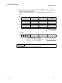
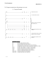
(2) Input data from slave address 4A to 31A (Buffer memory address
1H to 7H: Un\G1 to Un\G7)
The input data from the AS-i Ver. 2.11-compatible (Group A) and AS-i Ver. 2.04compatible I/O slaves are stored.
Bit
15
to
12 11
To
87
to
43
to
0
1H
7A
6A
5A
4A
2H
11A
10A
9A
8A
3H
15A
14A
13A
12A
4H
19A
18A
17A
16A
5H
23A
22A
21A
20A
6H
27A
26A
25A
24A
7H
31A
30A
29A
28A
ON: 1, OFF: 0
Example:
Bit
1H
15
I3
to
I2
12 11
I1
to
87
to
43
to
0
I0
Slave address 7A
I3
I2
I1
I0
I0 = ON
I1 = OFF
I2 = ON
I3 = ON
When 1H
b 15
14
13
12
1
1
0
1
TIP
• 0 is stored as the input from a non-connected slave.
• As the input from the slave address corresponding to the analog slave, the data
used for communication is stored.
3 - 15
3 - 15
3 SPECIFICATIONS
MELSEC-Q
(3) Input data from slave address 1B to 31B (Buffer memory address
8H to FH: Un\G8 to Un\G15)
The input data from the AS-i Ver. 2.11-compatible (Group B) I/O slaves are
stored.
Bit
15
to
8H
12 11
to
3B
87
2B
to
43
to
0
1B
9H
7B
6B
5B
4B
AH
11B
10B
9B
8B
BH
15B
14B
13B
12B
CH
19B
18B
17B
16B
DH
23B
22B
21B
20B
EH
27B
26B
25B
24B
FH
31B
30B
29B
28B
: Not used (0 fixed)
ON: 1, OFF: 0
Example:
Bit
8H
15
I3
to
I2
12 11
I1
to
87
to
43
to
0
I0
Slave address 3A
I3
I2
I1
I0
I0 = ON
I1 = OFF
I2 = ON
I3 = ON
When 8H
b 15
14
13
12
1
1
0
1
TIP
• 0 is stored as the input from a non-connected slave.
3 - 16
3 - 16
3 SPECIFICATIONS
MELSEC-Q
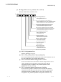
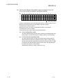
(4) EC flag (Buffer memory address 10H : Un\G16)
Example: Buffer memory address Un\G0
Bit 15 14 13 12 11 10 9 8 7 6 5 4 3 2 1 0
Bit 0: Configuration Error
0: No configuration error
1: Configuration error occurs
Bit 1: LDS_0 (Detection of slave addres 0 )
0: Slave of address 0 is not in list of detected slaves
1: Slave of address 0 is in list of detected slaves
Bit 2: Automatic Address Assignment Function
0: Automatic address assignment is invalid.
1: Automatic address assignment is valid.
Bit 3: Automatic Address Assignment Available
0: Automatic address assignment cannot be done.
1: Automatic address assignment can be done.
Bit 4: Configuration Mode Active
0: Not configuration mode
1: Configuration moe
Bit 5: Normal Operation Active
0: Normal operation
1: Other than normal operation
Bit 6: AS-i Power Fail (APF)
0: AS-i Power On (APO)
1: AS-i Power Fail (APF)
Bit 7: Off-line Phase Active
0: Not off-line phase
1: Off-line phase
Bit 8: Peripheral Faults
0: No Peripheral Fault
1: Peripheral Fault occurs
Bit 9 to 15: Use prohibited
(a) Bit 0: Configuration Error
Refer to "Section 3.4.2 (1) (a)".
(b) Bit 1: LDS_0 (Detection of slave address 0)
Bit 1 checks whether the AS-i system has a slave of slave address 0 or not.
Bit 1 turns ON when the QJ71AS92 detects slave 0.
(c) Bit 2: Automatic Address Assignment Function
Bit 2 checks whether the automatic slave address assignment function is
valid or invalid. Bit 2 turns ON when the automatic slave address
assignment function is enabled in the protected operation mode.
(Related item: Section 3.3.2 (9))
(d) Bit 3: Automatic Address Assignment Available
Bit 3 checks the operation conditions of the automatic slave address
assignment function. Bit 3 turns ON when the automatic slave address
assignment function is enabled and only one of the set slaves is not
recognised in the protected operation mode. (Refer to Section 4.5.4)
3 - 17
3 - 17
3 SPECIFICATIONS
MELSEC-Q
(e) Bit 4: Configuration Mode Active
Refer to "Section 3.4.2 (1) (d)".
(f)
Bit 5: Normal Operation Active
Refer to "Section 3.4.2 (1) (c)".
(g) Bit 6: AS-i Power Fail (APF)
Refer to "Section 3.4.2 (1) (b)".
(h) Bit 7: Off-line Phase Active
Bit 7 checks whether the QJ71AS92 is in the offline phase or not.
Bit 7 turns ON when the QJ71AS92 is in the offline phase.
(i)
Bit 8: Peripheral Faults
Bit 8 detects the peripheral fault of the slave. Bit 8 turns ON when the
QJ71AS92 detects the peripheral fault of the slave.
Check the detection conditions of a peripheral fault in the manual of the
slave.
Bit 8 turns ON when the QJ71AS92 is in the phase other than the normal
operation mode.
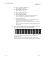
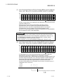
(5) List of Detected Slaves (LDS) (Buffer memory address 11H to 12H,
13H to 14H: Un\G17 to Un\G18, Un\G19 to Un\G20)
Bit
15
14
13
12
11
10
9
11H 15A 14A 13A 12A 11A 10A 9A
8
7
6
5
4
3
2
1
0
8A
7A
6A
5A
4A
3A
2A
1A
0
12H 31A 30A 29A 28A 27A 26A 25A 24A 23A 22A 21A 20A 19A 18A 17A 16A
13H 15B 14B 13B 12B 11B 10B 9B
8B
7B
6B
5B
4B
3B
2B
1B
14H 31B 30B 29B 28B 27B 26B 25B 24B 23B 22B 21B 20B 19B 18B 17B 16B
: Not used (0 fixed)
The bits corresponding to the slave addresses detected at startup of the
QJ71AS92 turn ON.
When the bit is ON, the slave corresponding to that bit is in the AS-i system.
When the bit is OFF, the slave corresponding to that bit is not in the AS-i system.
3 - 18
3 - 18
3 SPECIFICATIONS
MELSEC-Q
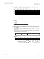
(6) List of Active Slaves (LAS) (Buffer memory address 15H to 16H,
17H to 18H: Un\G21 to Un\G22, Un\G23 to Un\G24)
Bit
15
14
13
12
11
10
9
15H 15A 14A 13A 12A 11A 10A 9A
8
7
6
5
4
3
2
1
8A
7A
6A
5A
4A
3A
2A
1A
0
16H 31A 30A 29A 28A 27A 26A 25A 24A 23A 22A 21A 20A 19A 18A 17A 16A
17H 15B 14B 13B 12B 11B 10B 9B
8B
7B
6B
5B
4B
3B
2B
1B
18H 31B 30B 29B 28B 27B 26B 25B 24B 23B 22B 21B 20B 19B 18B 17B 16B
: Not used (0 fixed)
The bits corresponding to the slave addresses ready for communication turn ON.
When the bit is ON, the slave corresponding to that bit is ready for
communication in the AS-i system.
When the bit is OFF, the slave corresponding to that bit is not ready for
communication in the AS-i system.
The active slave list (LAS) is made up as described below.
(a) In the configuration mode
The active slave list (LAS) has the same contents as the detected slave list
(LDS). Namely, the detected slaves are always ready for communication.
(b) In the protected operating mode
The active slave list (LAS) consists of the slaves that are ON in both the
detected slave list (LDS) and projected slave list (LPS (for read)). Namely,
only the slaves already registered to the projected slave list (LPS (for read))
from among the detected slaves (slaves that are ON in the detected slave
list (LDS)) are ready for communication.
(Related items: Section 3.4.2 (5), Section 3.4.2 (7))
3 - 19
3 - 19
3 SPECIFICATIONS
MELSEC-Q
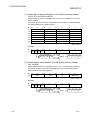
(7) List of Projected Slaves (LPS (For Read)) (Buffer memory address
19H to 1AH, 1BH to 1CH: Un\G25 to Un\G26, Un\G27 to Un\G28)
Bit
15
14
13
12
11
10
9
19H 15A 14A 13A 12A 11A 10A 9A
8
7
6
5
4
3
2
1
8A
7A
6A
5A
4A
3A
2A
1A
0
1AH 31A 30A 29A 28A 27A 26A 25A 24A 23A 22A 21A 20A 19A 18A 17A 16A
1BH 15B 14B 13B 12B 11B 10B 9B
8B
7B
6B
5B
4B
3B
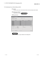
2B
1B
1CH 31B 30B 29B 28B 27B 26B 25B 24B 23B 22B 21B 20B 19B 18B 17B 16B
: Not used (0 fixed)
The bits corresponding to the registered slave addresses as the projected slaves
in the QJ71AS92 turn on.
When the bit is ON, the slave corresponding to that bit is ready for
communication in the AS-i system in the projected operation mode.
When the bit is OFF, the slave corresponding to that bit is not ready for
communication in the AS-i system in the projected operation mode.
At power-on of the programmable controller, the data Stored on the EEPROM in
the QJ71AS92 are used to make initialization.
TIP
• If the LPS has been set, communication cannot be made when the permanent
configuration differs from the actual configuration. (Related item: Section 3.5.1)
• To read/write the configuration, use the command buffer <request> (buffer
memory addresses: 101H to 13FH/141H to 17FH).
Refer to Section 3.5.1 for command details. (Related item: Section 4.5 (2))
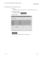
(8) List of slaves that differ from the settings (Buffer memory address
1DH to 1EH, 1FH to 20H: Un\G29 to Un\G30, Un\G31 to Un\G32)
Bit
15
14
13
12
11
10
9
1DH 15A 14A 13A 12A 11A 10A 9A
8
7
6
5
4
3
2
1
0
8A
7A
6A
5A
4A
3A
2A
1A
0
1EH 31A 30A 29A 28A 27A 26A 25A 24A 23A 22A 21A 20A 19A 18A 17A 16A
1FH 15B 14B 13B 12B 11B 10B 9B
8B
7B
6B
5B
4B
3B
2B
1B
20H 31B 30B 29B 28B 27B 26B 25B 24B 23B 22B 21B 20B 19B 18B 17B 16B
: Not used (0 fixed)
A configuration error occurs if the projected slave list (LPS (for read)) and
detected slave list (LDS) are different in the configuration contents.
The logical operation OR on the detected slave list (LDS) and projected slave list
(LPS (for read)) are performed. Then, the logical operation exclusive OR on the
result of the logical operation OR and the active slave list (LAS) is performed.
Conclusively, the result of the logical operation exclusive OR is stored.
The slave list that differs from the settings can be used to check the slave for a
configuration error occurrence.
11H(LDS)
1
1
1
1
15H(LAS)
0
1
0
1
19H(LPS)
1
1
0
0
1DH
1
0
1
0
On when the operation results are mismatched
0: OFF
1: ON
3 - 20
3 - 20
3 SPECIFICATIONS
MELSEC-Q
(9) Error Slave List (Buffer memory address 21H to 22H, 23H to 24H:
Un\G33 to Un\G34, Un\G35 to Un\G36)
Bit
15
14
13
12
11
10
9
21H 15A 14A 13A 12A 11A 10A 9A
8
7
6
5
4
3
2
1
8A
7A
6A
5A
4A
3A
2A
1A
0
22H 31A 30A 29A 28A 27A 26A 25A 24A 23A 22A 21A 20A 19A 18A 17A 16A
23H 15B 14B 13B 12B 11B 10B 9B
8B
7B
6B
5B
4B
3B
2B
1B
24H 31B 30B 29B 28B 27B 26B 25B 24B 23B 22B 21B 20B 19B 18B 17B 16B
: Not used (0 fixed)
The error slave list can be used to check the slave for a communication error
occurrence in the projected operation mode.
The result of Logical AND on the reverse active slave list (LAS) and the projected
slave list (LPS (for read)) is stored.
Example:
15H(LAS)
LAS
0
1
0
1
0
1
0
1
19H(LPS)
1
1
0
0
21H(Error slave list)
1
0
0
0
(10) Output data to slave addresses 1A to 3A (Buffer memory address
30H: Un\G48)
Output data to I/O slaves compatible with AS-i Ver. 2.11 (System A) or AS-i Ver.
2.04 are stored.
The values stored in the areas corresponding to the analog, non-connected and
non-detected slaves are invalid (ignored).
Bit
15
1H
to
12 11
to
3A
87
2A
to
43
to
0
(0000 fixed)
1A
ON: 1, OFF: 0
Example:
Bit
15
30H O3 O2
3 - 21
to
12 11
O1
to
87
to
43
to
0
O0
Slave address 3A
14
13
12
O3
1
0
1
O2
O1
O0 = ON
b 15
O1 = OFF When
30H 1
O0
O2 = ON
O3 = ON
3 - 21
3 SPECIFICATIONS
MELSEC-Q
(11) Output data to slave address 4A to 31A (Buffer memory address
31H to 37H: Un\G49 to Un\G55)
Output data to I/O slaves compatible with AS-i Ver. 2.11 (System A) or AS-i Ver.
2.04 are stored.
The values stored in the areas corresponding to the analog, non-connected and
non-detected slaves are invalid (ignored).
Bit
15
to
12 11
to
87
to
43
to
5A
0
31H
7A
6A
4A
32H
11A
10A
9A
8A
33H
15A
14A
13A
12A
34H
19A
18A
17A
16A
35H
23A
22A
21A
20A
36H
27A
26A
25A
24A
37H
31A
30A
29A
28A
ON: 1, OFF: 0
Example:
Bit
15
to
31H O3 O2
12 11
O1
to
87
to
43
to
0
O0
Slave address 7A
14
13
12
O3
1
0
1
O2
O0 = ON
b 15
O1 = OFF When
31H 1
O0
O2 = ON
O3 = ON
O1
(12) Output data to slave address 1B to 3B (Buffer memory address
38H: Un\G56)
Output data to I/O slaves compatible with AS-i Ver. 2.11 (System B) are stored.
The values stored in the areas corresponding to the non-connected and nondetected slaves are invalid (ignored).
Bit
15
38H
to
12 11
to
3B
87
2B
to
43
to
0
(0000 fixed)
1B
ON : 1, OFF : 0
Example:
Bit
15
38H O3 O2
3 - 22
to
12 11
O1
to
87
to
43
to
0
O0
Slave address 3A
14
13
12
O3
1
0
1
O2
O1
O0 = ON
b 15
O1 = OFF When
38H 1
O0
O2 = ON
O3 = ON
3 - 22
3 SPECIFICATIONS
MELSEC-Q
(13) Output data to slave addresses 4B to 31B (Buffer memory address
39H to 3FH: Un\G57 to Un\G63)
Output data to I/O slaves compatible with AS-i Ver. 2.11 (System B) are stored.
The values stored into the areas corresponding to the non-connected and nondetected slaves are invalid (ignored).
Bit
15
to
12 11
to
87
to
43
to
0
39H
7B
6B
5B
4B
3AH
11B
10B
9B
8B
3BH
15B
14B
13B
12B
3CH
19B
18B
17B
16B
3DH
23B
22B
21B
20B
3EH
27B
26B
25B
24B
3FH
31B
30B
29B
28B
ON: 1, OFF: 0
Example:
Bit
15
to
39H O3 O2
12 11
O1
to
87
to
43
to
0
O0
Slave address 7A
14
13
12
O3
1
0
1
O2
O1
O0 = ON
b 15
O1 = OFF When
39H 1
O0
O2 = ON
O3 = ON
(14) List of Projected Slaves (LPS (For Write)) (Buffer memory address
49H to 4AH, 4BH to 4CH: Un\G73 to Un\G74, Un\G75 to Un\G76)
Bit
15
14
13
12
11
10
9
49H 15A 14A 13A 12A 11A 10A 9A
8
7
6
5
4
3
2
1
8A
7A
6A
5A
4A
3A
2A
1A
0
4AH 31A 30A 29A 28A 27A 26A 25A 24A 23A 22A 21A 20A 19A 18A 17A 16A
4BH 15B 14B 13B 12B 11B 10B 9B
8B
7B
6B
5B
4B
3B
2B
1B
4CH 31B 30B 29B 28B 27B 26B 25B 24B 23B 22B 21B 20B 19B 18B 17B 16B
: Not used (0 fixed)
If the bit corresponding to the number of the slave to be communicated with and
Y13 are turned ON, data in this area will be registered in the QJ71AS92 and be
reflected into the List of projected slaves (LPS (for read)) (buffer memory
address: 19H to 1CH).
(Related item: Section 4.5 (2))
TIP
• The projected slave list (LPS (for write)) is handled as a 64-bit length in the
QJ71AS92. Therefore, if data is written to only the buffer memory address 49H,
the contents of the buffer memory address 4AH to 4CH are also made valid as
data.
• When communicating with the slave that has been judged as ready for
communication in the active slave list (LAS) (buffer memory addresses: 15H to
18H), easy registration of the projected slave list (LPS (for read)) and configuration
are enabled by using the command buffer <request> 201H.
3 - 23
3 - 23
3 SPECIFICATIONS
MELSEC-Q
(15) Command buffer <request>
(Buffer memory address 55H to 59H: Un\G85 to Un\G89)
Buffer memory address
Item
55H (85)
AS-i command buffer <request>
56H (86)
AS-i command buffer <data word 0>
57H (87)
AS-i command buffer <data word 1>
58H (88)
AS-i command buffer <data word 2>
59H (89)
AS-i command buffer <data word 3>
(a)
After data is written to the command buffer <request> and <data words 0 to
3> and, Y12 is turned ON.
The QJ71AS92 executes the command buffer <request> when Y12 turns
ON. At this time, "08" (request code in execution) is stored into the
*1
command buffer <result>.
*1 If necessary, the QJ71AS92 reads the command buffer <data words 0 to
3>.
After the command execution is completed, the QJ71AS92 stores the result
*2
into the command buffer <result> and turns ON X2.
*2 When the results are added with data, the data is stored into the data
word for extended command buffer <result>.
(Related item: Section 3.4.2 (22))
(b)
(c)
TIP
Refer to Section 3.5.1 for the command buffer <request> list.
(16) Command buffer <result>
(Buffer memory address 25H to 29H: Un\G37 to Un\G41)
Buffer memory address
Item
25H (37)
AS-i command buffer <result>
26H (38)
AS-i command buffer <data word 0>
27H (39)
AS-i command buffer <data word 1>
28H (40)
AS-i command buffer <data word 2>
29H (41)
AS-i command buffer <data word 3>
The QJ71AS92 stores the result of executing the command buffer <request>.
(Related item: Section 3.4.2 (21))
TIP
Refer to Section 3.5.1 for the command buffer <request> list.
3 - 24
3 - 24
3 SPECIFICATIONS
MELSEC-Q
(17) Current Error Code, Error Code History 1-5
(Buffer memory address C0H to C5H: Un\G192 to Un\G197)
The error code currently detected by the QJ71AS92 and the history of maximum
five error codes are stored.
Buffer memory address
Item
C0H (192)
Current Error Code
C1H (193)
Error Code History 1
C2H (194)
Error Code History 2
C3H (195)
Error Code History 3
C4H (196)
Error Code History 4
C5H (197)
Error Code History 5
C0H and C1 H store the latest error code. When the error is reset, C0H stores "0".
In C1H, the error code remains as-is.
Example) When an error occurs, the error codes are stored as indicated below.
C1H (193)
Latest Error Code History
C2H (194)
Error Code History 1
C3H (195)
Error Code History 2
C4H (196)
Error Code History 3
C5H (197)
Error Code History 4
Shift
TIP
Refer to Section 8.3.1 for error codes.
(18) List of Peripheral Faults (LPF) (Buffer memory address D0H to D1H,
D2H to D3H: Un\G208 to Un\G209, Un\G210 to Un\G211)
Each bit corresponds to the peripheral fault occurrence status of the
corresponding slave address (1A to 31A, 1B to 31B).
When the bit is ON, it indicates that a peripheral fault has occurred in the slave
corresponding to that bit. (When any of the bits is ON, the peripheral fault bit of
the EC flag (buffer memory address: 10H) turns ON.)
When the bit is OFF, it indicates that a peripheral fault has not occurred in the
slave corresponding to that bit.
The peripheral fault slave list is a function compatible with AS-i Ver. 2.11.
For the peripheral fault detection conditions, refer to the manual of the slave
used.
Bit
15
14
13
12
11
10
9
D0H 15A 14A 13A 12A 11A 10A 9A
8
7
6
5
4
3
2
1
8A
7A
6A
5A
4A
3A
2A
1A
0
D1H 31A 30A 29A 28A 27A 26A 25A 24A 23A 22A 21A 20A 19A 18A 17A 16A
D2H 15B 14B 13B 12B 11B 10B 9B
8B
7B
6B
5B
4B
3B
2B
1B
D3H 31B 30B 29B 28B 27B 26B 25B 24B 23B 22B 21B 20B 19B 18B 17B 16B
: Not used (0 fixed)
3 - 25
3 - 25
3 SPECIFICATIONS
MELSEC-Q
(19) Analog input data, Analog output data (Buffer memory address E0H
to 15FH, 160H to 1DFH: Un\G224 to Un\G351, Un\G352 to
Un\G479)
Address
Hexadecimal
Decimal
E0H to E3H
224 to 227
E4H to E7H
228 to 231
E8H to EBH
232 to 235
ECH to EFH
236 to 239
F0H to F3H
240 to 243
F4H to F7H
244 to 247
F8H to FBH
248 to 251
FCH to FFH
252 to 255
100H to 103H 256 to 259
104H to 107H 260 to 263
108H to 10BH 264 to 267
10CH to 10FH 268 to 271
110H to 113H 272 to 275
114H to 117H 276 to 279
118H to 11BH 280 to 283
11CH to 11FH 284 to 287
120H to 123H 288 to 291
124H to 127H 292 to 295
128H to 12BH 296 to 299
12CH to 12FH 300 to 303
130H to 133H 304 to 307
134H to 137H 308 to 311
138H to 13BH 312 to 315
13CH to 13FH 316 to 319
140H to 143H 320 to 323
144H to 147H 324 to 327
148H to 14BH 328 to 331
14CH to 14FH 332 to 335
150H to 153H 336 to 339
154H to 157H 340 to 343
158H to 15BH 344 to 347
15CH to 15FH 348 to 351
Address
Hexadecimal
Decimal
160H to 163H 352 to 355
164H to 167H 356 to 359
168H to 16BH 360 to 363
16CH to 16FH 364 to 367
170H to 173H 368 to 371
174H to 177H 372 to 375
178H to 17BH 376 to 379
17CH to 17FH 380 to 383
180H to 183H 384 to 387
184H to 187H 388 to 391
188H to 18BH 392 to 395
18CH to 18FH 376 to 399
190H to 193H 400 to 403
194H to 197H 404 to 407
198H to 19BH 408 to 411
19CH to 19FH 412 to 415
Analog input
1A0H to 1A3H 416 to 419
1
data *
1A4H to 1A7H 420 to 423
1A8H to 1ABH 424 to 427
1ACH to 1AFH 428 to 431
1B0H to 1B3H 432 to 435
1B4H to 1B7H 436 to 439
1B8H to 1BBH 440 to 443
1BCH to 1BFH 424 to 447
1C0H to 1C3H 448 to 451
1C4H to 1C7H 452 to 455
1C8H to 1CBH 456 to 459
1CCH to 1CFH 460 to 463
1D0H to 1D3H 464 to 467
1D4H to 1D7H 468 to 471
1D8H to 1DBH 472 to 475
1DCH to 1DFH 476 to 479
Details
Invalid (0 fixed)
Slave address 1
Slave address 2
Slave address 3
Slave address 4
Slave address 5
Slave address 6
Slave address 7
Slave address 8
Slave address 9
Slave address 10
Slave address 11
Slave address 12
Slave address 13
Slave address 14
Slave address 15
Slave address 16
Slave address 17
Slave address 18
Slave address 19
Slave address 20
Slave address 21
Slave address 22
Slave address 23
Slave address 24
Slave address 25
Slave address 26
Slave address 27
Slave address 28
Slave address 29
Slave address 30
Slave address 31
Analog
output data
*1: "7FFFH" is stored when no communication is made.
Example: Buffer memory address: Un\G228 to Un\G231
Buffer memory address
E4H (228)
E5H (229)
E6H (230)
E7H (231)
Item
Analog input data from slave address 1 (Channel 1)
Analog input data from slave address 1 (Channel 2)
Analog input data from slave address 1 (Channel 3)
Analog input data from slave address 1 (Channel 4)
Example: Buffer memory address: Un\G356 to Un\G359
Buffer memory address
164H (356)
165H (357)
166H (358)
167H (359)
Item
Analog output data to slave address 1 (Channel 1)
Analog output data to slave address 1 (Channel 2)
Analog output data to slave address 1 (Channel 3)
Analog output data to slave address 1 (Channel 4)
REMARK
For the range of analog output data, refer to the manual of each analog slave.
3 - 26
3 - 26
3 SPECIFICATIONS
MELSEC-Q
(20) Number of I/O Points (Buffer memory address 1E0H to 1FFH, 200H
to 21FH: Un\G480 to Un\G511, Un\G512 to Un\G543)
The following table lists the numbers of I/O points and analog I/O points of the
slaves in the configuration are displayed.
Address
Hexadecimal Decimal
1E0H
1E1H
1E2H
1E3H
1E4H
1E5H
1E6H
1E7H
1E8H
1E9H
1EAH
1EBH
1ECH
1EDH
1EEH
1EFH
1F0H
1F1H
1F2H
1F3H
1F4H
1F5H
1F6H
1F7H
1F8H
1F9H
1FAH
1FBH
1FCH
1FDH
1FEH
1FFH
480
481
482
483
484
485
486
487
488
489
490
491
492
493
494
495
496
497
498
499
500
501
502
503
504
505
506
507
508
509
510
511
Address
Hexadecimal Decimal
Details
Invalid (0 fixed)
Slave address 1A
Slave address 2A
Slave address 3A
Slave address 4A
Slave address 5A
Slave address 6A
Slave address 7A
Slave address 8A
Slave address 9A
Slave address 10A
Slave address 11A
Slave address 12A
Slave address 13A
Slave address 14A
Slave address 15A
Slave address 16A
Slave address 17A
Slave address 18A
Slave address 19A
Slave address 20A
Slave address 21A
Slave address 22A
Slave address 23A
Slave address 24A
Slave address 25A
Slave address 26A
Slave address 27A
Slave address 28A
Slave address 29A
Slave address 30A
Slave address 31A
I/O data
200H
201H
202H
203H
204H
205H
206H
207H
208H
209H
20AH
20BH
20CH
20DH
20EH
20FH
210H
211H
212H
213H
214H
215H
216H
217H
218H
219H
21AH
21BH
21CH
21DH
21EH
21FH
512
513
514
515
516
5157
518
519
520
521
522
523
524
525
526
527
528
529
530
531
532
533
534
535
536
537
538
539
540
541
542
543
Details
Invalid (0 fixed)
Slave address 1B
Slave address 2B
Slave address 3B
Slave address 4B
Slave address 5B
Slave address 6B
Slave address 7B
Slave address 8B
Slave address 9B
Slave address 10B
Slave address 11B
Slave address 12B
Slave address 13B
Slave address 14B
Slave address 15B
Slave address 16B
Slave address 17B
Slave address 18B
Slave address 19B
Slave address 20B
Slave address 21B
Slave address 22B
Slave address 23B
Slave address 24B
Slave address 25B
Slave address 26B
Slave address 27B
Slave address 28B
Slave address 29B
Slave address 30B
Slave address 31B
I/O data
Example: Buffer memory address Un\G481
Bit 15 14 13 12 11 10 9 8 7 6 5 4 3 2 1 0
Bits 0 to 3: Input points of slave address 1A (unit: bit)
Bits 4 to 7: Output points of slave address 1A (unit: bit)
Bits 8 to 11: Analog input points of slave address 1A (unit: word)
Bits 12 to 15: Analog output points of slave address 1A (unit: word)
3 - 27
3 - 27
3 SPECIFICATIONS
MELSEC-Q
(21) Extended Command Buffer <Result>
(Buffer memory address 300H to 36DH: Un\G768 to Un\G877)
The result of executing any of the following commands with the command buffer
<request> (buffer memory address: 55H) is stored.
1
• Slave ID read command (command: 301H) *
1
• Slave diagnostic information read command (command: 303H) *
1
• Slave parameter read command (command: 305H) *
*1: Refer to Section 3.5.1 for command details.
Buffer memory address
Item
300H (768)
Extended Command Buffer <Result data word 0>
301H (769)
Extended Command Buffer <Result data word 1>
•
•
•
•
•
•
36CH (876)
Extended Command Buffer <Result data word 108>
36DH (877)
Extended Command Buffer <Result data word 109>
(22) Extended Command Buffer <Request (Data)>
(Buffer memory address 400H to 46DH: Un\G1024 to Un\G1133)
Used when the following command is executed with the command buffer
<request> (buffer memory address: 55H).
1
• Slave parameter write command (command: 307H) *
*1: Refer to Section 3.5.1 for command details.
Buffer memory address
Extended Command Buffer <Request data word 0>
401H (1025)
Extended Command Buffer <Request data word 1>
•
•
•
3 - 28
Item
400H (1024)
•
•
•
46CH (1132)
Extended Command Buffer <Request data word 108>
46DH (1133)
Extended Command Buffer <Request data word 109>
3 - 28
3 SPECIFICATIONS
MELSEC-Q
3.5 Command List
This section provides the command buffer <request>/<result>.
3.5.1 Command Buffer <Request> List
The command buffer <request> lists are indicated below.
A: AS-i Ver. 2.11-compatible Group A I/O slave, Analog slave,
AS-i Ver. 2.04-compatible I/O slave
B: AS-i Ver. 2.11-compatible Group B I/O slave
1): Off-line phase
2): Configuration mode
3): Protected operation mode
: Enabled,
Command
Details
code
Target Slave
A
01H to 1FH
Writes the value of the command buffer <request (data word 0)> to the
*1
actual parameter of the slave address n (n = request code).
21H to 3FH
Writes the value of the command buffer <request (data word 0)> to the
*1
actual parameter of the slave address n (n = request code - 20H).
41H to 5FH
Reads the actual parameter of the slave address n (n = request code
- 40H).
The result is written to the command buffer <result (data word 0)>.
61H to 7FH
Reads the actual parameter of the slave address n (n = request code
- 60H).
The result is written to the command buffer <result (data word 0)>.
81H to 9FH
Writes the value of the command buffer <request (data word 0)> to the
*1
permanent parameter of the slave address n (n = request code 80H).
A1H to BFH
Writes the value of the command buffer <request (data word 0)> to the
*1
permanent parameter of the slave address n (n = request code A0H).
C1H to DFH
Reads the permanent parameter of the slave address n (n = request
code - C0H).
The result is written to the command buffer <result (data word 0)>.
E1H to FFH
Reads the permanent parameter
B
: Disabled
Operating
Status
1)
2)
3)
*1
*1
*1
*1
of the slave address n (n = request
code - E0H).
The result is written to the command buffer <result (data word 0)>.
3 - 29
3 - 29
3 SPECIFICATIONS
MELSEC-Q
: Enabled,
Command
code
101H to 11FH
121H to 13FH
141H to 15FH
161H to 17FH
181H to 19FH
1A1H to 1BFH
1C0H
1C1H to 1DFH
1E1H to 1FFH
200H
201H
202H
203H
204H
300H *3
3 - 30
Details
Target Slave
A
B
: Disabled
Operating
Status
1)
2)
3)
*2
Reads the actual configuration of the slave address n (n = request
code - 100H).
The result is written to the command buffer <result (data word 0)>.
*2
Reads the actual configuration of the slave address n (n = request
code - 120H).
The result is written to the command buffer <result (data word 0)>.
Writes the value of the command buffer <request (data word 0)> to the
*2
permanent configuration of the slave address n (n = request code 140H).
Writes the value of the command buffer <request (data word 0)> to the
*2
permanent configuration of the slave address n (n = request code 160H).
*2
Reads the permanent configuration of the slave address n (n =
request code - 180H).
The result is written to the command buffer <result (data word 0)>.
*2
Reads the permanent configuration of the slave address n (n =
request code - 1A0H).
The result is written to the command buffer <result (data word 0)>.
Reads the number of AS-i power fail times to the data word 0, and
resets it.
Reads the number of wrong response times of the slave address n (n =
request code - 1C0H) to the data word 0, and clears it.
Reads the number of wrong response times of the slave address n (n =
request code - 1E0H) to the data word 0, and clears it.
Changes the slave address n (n = data word 0) into m (m = data word
1). n, m = set in 01H to 1FH.
Changes the slave address n (n = data word 0) into m (m = data word
1). n, m = set in 21H to 3FH (slave address + 20H).
Stores the actual configuration of AS-i.
(Copies the active slave list (LAS) to the projected slave list (LPS (for
read)) and copies the actual configuration to the permanent
configuration.)
Stores the actual parameters of AS-i to the permanent parameters.
Sets the SET and MODE switches to Invalid/Valid.
Command buffer <request (data word 0)>
0: Valid (default), 1: Invalid
Reads and clears the illegal slave list.
The result is written to the command buffer <result (data words 0, 1)>.
Writes the value of the command buffer <request (data word 0)> to the
extension ID code 1 of the slave address 0.
3 - 30
3 SPECIFICATIONS
MELSEC-Q
: Enabled,
Command
code
301H
*3
303H
*3
305H
*3
307H
*3
3 - 31
Details
Target Slave
A
B
: Disabled
Operating
Status
1)
2)
3)
Reads the ID of the slave address n (n = data word 0). The Execution
result is stored as follows.
Command buffer <request (data word 0)>
(Buffer memory address: 56H): Stores the slave address.
Command buffer <result>
(Buffer memory address: 25H): Stores the Execution result.
Command buffer <result (data word 0)>
(Buffer memory address: 26H): Stores the size of the read data.
Extension command buffer <result>
(Buffer memory address: 300H): Stores the read data.
*The read data is up to 220 bytes.
Reads the diagnostic information of the slave address n (n = data word
0). The Execution result is stored as follows.
Command buffer <request (data word 0)>
(Buffer memory address: 56H): Stores the slave address.
Command buffer <result>
(Buffer memory address: 25H): Stores the Execution result.
Command buffer <result (data word 0)>
(Buffer memory address: 26H): Stores the size of the read data.
Extension command buffer <result>
(Buffer memory address: 300H): Stores the read data.
*The read data is up to 220 bytes.
Reads the parameters of the slave address n (n = data word 0). The
Execution result is stored as follows.
Command buffer <request (data word 0)>
(Buffer memory address: 56H): Stores the slave address.
Command buffer <result>
(Buffer memory address: 25H): Stores the Execution result.
Command buffer <result (data word 0)>
(Buffer memory address: 26H): Stores the size of the read data.
Extension command buffer <result>
(Buffer memory address: 300H): Stores the read data.
*The read data is up to 220 bytes.
Writes the parameters to the slave address n (n = data word 0). The
Execution result is stored as follows.
Command buffer <request (data word 0)>
(Buffer memory address: 56H): Stores the slave address.
Command buffer <request (data word 1)>
(Buffer memory address: 26H): Stores the size of the written data.
Extension command buffer <request (data)>
(Buffer memory address: 400H): Sets the written data.
Extension command buffer <result>
(Buffer memory address: 300H): Stores the written data.
*The read data is up to 220 bytes.
3 - 31
3 SPECIFICATIONS
MELSEC-Q
*1
Name
Description
Actual parameter
Parameter that the target slave has
Permanent parameter
Slave parameter that the QJ71AS92 has
For the actual parameters, refer to the manual of the slave used.
*2: Consists of the I/O code and ID code of the slave. The data of the inactive slave are default values
(FFH).
When communicating in the projected operation mode, the permanent configuration of the slave whose
bit in the LPS (for read) (buffer memory addresses: 19H to 1CH) is ON must match the actual
configuration of the corresponding slave connected.
Name
Description
Actual configuration
I/O code and ID code that the slave holds.
Permanent configuration
I/O code and ID code that the QJ71AS92 holds.
(Extension ID code 1, 2 .• • • Added to AS-i Ver. 2.11.)
(Extension ID code 1, 2 • • • Added to AS-i Ver. 2.11.)
Configuration data structure of AS-i Ver. 2.11-compatible slave
8 lower-order bits
8 higher-order bits
4 higher-order bits
4 lower-order bits
4 higher-order bits
4 lower-order bits
Extension ID code 2
Extension ID code 1
ID code
I/O code
Configuration data structure of AS-i Ver. 2.04-compatible slave
Last 8 bits
First 8 bits
First 4 bits
Last 4 bits
Not used (fixed to FFH)
ID code
I/O code
For the I/O and ID codes, refer to the manual of the slave used.
This data can be stored on the EEPROM of the QJ71AS92. For how to store the data to the EEPROM, See
Section 3.3.2 (12) or Section 4.5.1.
*3 This command can be used with the slave compatible with the slave profile S-7.4.
For the profile of the slave used, refer to the manual of the slave.
3 - 32
3 - 32
3 SPECIFICATIONS
MELSEC-Q
3.5.2 Command Buffer <Result> List
The following table lists the command buffer <result>.
Result Value
00H
The command was not executed.
01H
The request code was executed.
02H
The target slave address does not exist.
03H
The slave of slave address 0 exists.
04H
The target slave address is used by another slave.
05H
The target slave address cannot be erased.
06H
The target slave address cannot be set.
07H
3 - 33
Description
The slave address cannot be written to the nonvolatile memory of
the slave.
08H
The request code is in execution.
09H
The request code is wrong.
0AH
The data word value is outside the setting range.
0BH
The extension ID code 1 was not stored correctly.
0CH
The extension ID code 1 could not be read correctly.
3 - 33
4 SETTINGS AND PROCEDURES FOR OPERATION
MELSEC-Q
4 SETTINGS AND PROCEDURES FOR OPERATION
This section explains the procedures, name of each part, installation, connection to the
AS-i system and settings for using the QJ71AS92 in the AS-i system.
4.1 Outline Procedures for Operation
The following chart shows the procedures for using the QJ71AS92 in the AS-i system.
Start
Wire the AS-i cable
See section 4.4
4
Turn the AS-i power supply ON
Turn the programmable controller
system power supply ON
Set the slave address
Create the program
See Section 4.5
See Chapter 7
Run the QJ71AS92
End
4-1
4-1
4 SETTINGS AND PROCEDURES FOR OPERATION
MELSEC-Q
4.2 Part Names
2)
3)
4)
1)
5)
6)
7)
4
No.
Name
Details
Shows the slave address or error code of the QJ71AS92.
Number
1)
“CODE” LED
2)
LED Display
0
1
2
3
4
5
Alphabet
6
7
8
9
p
g
d
Turned on/off to indicate the operating statuses of the QJ71AS92. (Refer to Section 4.2.1)
When the slave address 0 to 31 are displayed on "Code", the slave types are also displayed.
3)
“A” LED
4)
“B” LED
5)
MODE Switch
6)
SET Switch
7)
Connector
4-2
A LED
B LED
Details
OFF
OFF
AS-i Ver. 2.04-compatible I/O slave, Analog slave,
Ver. 2.11 non-grouped I/O slave
ON
OFF
AS-i Ver. 2.11-compatible Group A I/O slave
OFF
ON
AS-i Ver. 2.11-compatible Group B I/O slave
ON
ON
- (for future use)
Used to change between the protected operation mode and configuration mode.
(Refer to Section 4.5)
Used to set the address to the slave or set parameters to the QJ71AS92.
(Refer to Section 4.5)
Connected to the AS-i system using the AS-i cable. (Refer to Section 4.4.2)
4-2
4 SETTINGS AND PROCEDURES FOR OPERATION
MELSEC-Q
4.2.1 LED Display
The QJ71AS92 LEDs display the following details.
LED name
Coler
RUN
Details
Lit when the module is normally operating.
green
On = Normal operation
Off = Hardware error detected or power not supplied.
U ASI
Lit when AS-i power is supplied.
green
On = Power is supplied from AS-i bus.
Off = Power is not supplied from AS-i bus.
CM
Lit when the module is operating in configuration mode.
yellow
On = Configuration mode or parameters being stored.
Off = Protected operation mode
ERR.
Lit when an error occurs.
red
On = Alarm detected.
Example) Slave address alarm, parameter error and so forth.
Off = Alarm not detected.
PRG ENA.
Lit when automatic slave address assignment function is ready.
yellow
(See Section 4.5.4)
On = Ready.
Off = Not ready
S ERR.
4-3
red
- (for future use)
4-3
4 SETTINGS AND PROCEDURES FOR OPERATION
MELSEC-Q
4.3 Mounting and Installation
This section describes the precautions to be observed when handling the QJ71AS92
from unpacking to installation, and the installation environment. are explained in this
section.
4.3.1 Precautions for Handling
CAUTION
• Use the programmable controller in an environment that meets the general specifications in CPU
module User’s Manual.
Using the programmable controller in the environments outside the ranges stated in the general
specifications will cause electric shock, fire, misoperation, or damage to/deterioration of the product.
• While pressing the lever on the lower part of the module, fully insert the module fixing latch into the hole
of the base unit, snap the module into place, and tighten the module fixing screws with the specified
torque.
Failure to observe this could result in damage to the screws or module, module falling, short or
misoperation.
• Always shut off all phases of the programmable controller power supply and AS-i power supply
externally before mounting or removing the module.
Failure to shut off all phases could lead to product damage.
• Do not touch conductive parts or electronic components of the module with your bare hands.
This could cause Misoperation or failure of the module.
(1) The module case and communication connector are made of resin, so take care
not to drop or apply strong impacts.
(2) Tighten the screws such as module fixing screws within the following ranges.
Screw location
Tightening torque range
Module fixing screw
(normally not required) (M3 screw)
*1
Communication connector mounting screw
Communication connector wiring mounting screw
0.36 to 0.48 N.m
0.40 to 0.50 N.m
0.50 to 0.60 N.m
*1 The module can be easily fixed onto the base unit using the hook at top of the module.
However, it is recommended to secure the module with the module fixing screw if the
module is subject to significant vibration.
4.3.2 Installation Environment
Refer to the User's Manual of the CPU module being used for details on the installation
environment.
4-4
4-4
4 SETTINGS AND PROCEDURES FOR OPERATION
MELSEC-Q
4.4 Connection to AS-i System
This section describes the precautions to observe when connecting the QJ71AS92 to
the AS-i system, and the wiring methods.
4.4.1 Precautions for wiring
DANGER
• Switch off all phases of the programmable controller power supply and AS-i power supply outside the
programmable controller before starting installing or wiring work.
If all phases are not switched off, electric shock will occur or the product will be damaged.
• Be sure to install the terminal covers included with the product, when turning on the power or operating
the product after installation and wiring is completed.
Failure to install the terminal cover could lead to electric shocks.
CAUTION
• Always confirm the products terminal layout before wiring to the module.
Miswiring could lead to fires or faults.
• Tighten terminal screws within the specified torque.
Failure to observe this could result in damage to the screws or module, short or misoperation.
• Make sure that no foreign matter such as chips or wire offcuts gets inside the module.
It will cause fire, failure, or misoperation.
• A label is installed at the upper part of a module to prevent the entry of foreign matters. Do not remove
the label during wiring. However, be sure to remove it for heat dissipation during system operation.
• To connect the AS-i cable to the module, the cable must be securely fixed. Please be sure to run it in a
duct, or clamp it.
Failure to observe this could cause the unstable cable connection, resulting in damage to the cable or
module by carelessly pulling the cable, or the system malfunction due to poor cable connection.
• Do not bundle AS-i cable together with main circuit or power lines, or lay them close to these lines.
As a guide, separate these lines by a distance of at least 100 mm, otherwise misoperations may occur
due to noise.
• When removing the AS-i cable from a module, do not pull it out by hand. Always be sure to unscrew the
module mounting screws in advance.
If the cable is pulled while being connected to the module, it could cause damage to the cable or
module, or the system malfunction due to poor cable connection.
(1) The overall distance is up to 100m.
The distance can be increased 100m by use of one repeater.
Since up to two repeaters can be used in series, the overall distance can be
increased up to 300m.
4-5
4-5
4 SETTINGS AND PROCEDURES FOR OPERATION
MELSEC-Q
4.4.2 Wiring
Be sure connect the QJ71AS92 to the AS-i system with the AS-i cable.
An example of wiring to the QJ71AS92 is shown below.
(Confirm each module being used for the AS-i power supply and slave terminal layout.)
Strip the AS-i cable by about 7mm and plug it to the connector.
QJ71AS92
AS-i
power
supply
AS-i cable
(Brown)
(Blue)
*1
ASI+
*1
ASI+
ASI(Brown)
AS-i cable
Slave
ASI-
(Blue)
(FG) *2
AS-i cable
Slave
*1: The ASI+ and ASI- terminals are connected within the module, respectively.
*2: Always ground the FG terminal to the protective ground conductor.
4-6
4-6
4 SETTINGS AND PROCEDURES FOR OPERATION
MELSEC-Q
4.5 Start-Up
After powering on the programmable controller, the QJ71AS92 is placed in the normal
operation status (ready to communicate data with the slaves) via the following
communication phases.
Off-line phase
In this phase, the QJ71AS92 is initialized. Communication in the AS-i system is not started.
If sufficient power is not supplied from the AS-i power supply to the AS-i system, the
QJ71AS92 remains in the offline phase. (The "U ASI" LED is not lit.)
When AS-i power is supplied, the QJ71AS92 switches to the detection phase.
Detection phase
In this phase, the QJ71AS92 checks for the slaves that are ready for communication in the
AS-i system. It remains in the detection phase until it finds at least one slave.
Activation phase
In this phase, the slaves found by the QJ71AS92 in the detection phase become ready to
communicate.
Normal operation
In the normal operation status, the QJ71AS92 can communicate data with all the slaves
that are ready for communication. The QJ71AS92 sends a management message to check
for a newly connected slave, and if it exists, makes it ready for communication.
The normal operation phase has the configuration mode and protected operation
mode. The QJ71AS92 is put in either mode that has been registered to the EEPROM
after powering on.
The configuration mode and protected operation mode can be switched between each
other by writing an instruction (command) from the CPU module.
(a) Configuration mode
In this mode, the QJ71AS92 communicates with all detected slaves.
(However, output data is not output to the slave of slave address 0.)
This mode is used to set the slave address.
(b) Protected operation mode
In this mode, the QJ71AS92 communicates with all registered slaves.
Normally, this mode is used to make communication.
To use this mode, the configuration data of the slave must be registered.
If a slave not registered as configuration data is detected at start of
communication, a configuration error will occur.
4-7
4-7
4 SETTINGS AND PROCEDURES FOR OPERATION
MELSEC-Q
(1) Method of setting the slave address
There are two methods of setting the slave address.
Select either of the followings as necessary.
(a) Using the switches (on the QJ71AS92 front panel):
Setting can be made without a peripheral device.
(b) Using the command (for the QJ71AS92):
Setting can be made in the environment where the module cannot be
operated (the module is installed in the inaccessible place far end of an
operator panel).
The following chart shows the operation sequence of each method.
Slave address setting *1
Using the switches
<Select the configuration mode>
If the CM LED is not ON, press the MODE switch until the
CM LED is lit to select the configuration mode.
<Method of erasing the slave address (set the slave
address to 0)>
When the slave address you want to erase is displayed on
the CODE LED, press the SET switch for more than
5 seconds. (See Section 4.5.3)
<Method of setting the slave address to the slave of slave
address 0> (See Section 4.5.2)
1) Press the SET switch to display the address you want to
set on the CODE LED.
2) Hold down the SET switch until the address displayed on
the CODE LED flickers.
3) After it has flickered, press the SET switch again.
This sets the slave address displayed on the CODE LED
to the slave of slave address 0.
Using the command
(Program or GX Configurator-AS *2)
<Send the command>
1) Set 200H in the command buffer <request>
(buffer memory address 55H).
2) Set the current slave address in the command buffer
<request (data word 0)> (buffer memory address 56H). *3
3) Set a new slave address in the command buffer
<request (data word 1)> (buffer memory address 57H). *3
4) Turn Y12 ON (command request).
5) Turn Y12 OFF after making sure that X12
(command completion) has turned ON.
6) Check the result of the command buffer <result>
(buffer memory address 25H).
*2: See Section 5.6 for the operation of GX Configurator-AS.
*3: See Section 3.5.1 for the values to be set to the command
data.
*1: The slave address can be set to only the slave that has
been set to address 0.
For details of the method of using the switches, See
Section 4.5.1 and later.
4-8
4-8
4 SETTINGS AND PROCEDURES FOR OPERATION
MELSEC-Q
(2) Method of registering the configuration data to the QJ71AS92
Before starting operation in the protected operation mode, the configuration data
of the slave that is ready for communication must be registered to the
QJ71AS92.
There are two methods of registering the configuration date just as 4.5.(1)
”Method of setting the slave address”. Register the configuration data by using
the switches or by using the command.
The following chart shows the operation sequence of each method.
Configuration data registration method
Using the switches
Using the commands
(Program or GX Configurator-AS *5)
<Select the configuration mode>
If the CM LED is not ON, press the MODE switch until
the CM LED is lit to select the configuration mode.
<Select the configuration mode>
If the CM LED is not ON, turn Y16 (configuration mode)
from OFF to ON to OFF to select the configuration mode.
<Method of registering the configuration data>
Press the MODE switch until the CM LED turns off.
This registers the configuration data and switches to the
protected operation mode. *4
<Method of registration after clearing the previous
configuration data>
1) Set 201H in the command buffer <request>
(buffer memory address 55H).
2) Turn Y12 ON (command request).
3) Turn Y12 OFF after making sure that X12
(command completion) has turned ON.
4) Check the result of the command buffer <result>
(buffer memory address 25H).
<Method of addition/deletion to the previous configuration
data>
1) Set the LPS (for write) (buffer memory addresses 49H
to 4CH) and turn Y13 ON
(configuration registration request).
2) Turn Y13 OFF after confirming that X3 (configuration
registration completion) has turned ON.
3) Set the permanent configuration setting command:
141H to 17FH in the command buffer <request>
(buffer memory addresses: 55H to 56H). *6
4) Turn Y12 ON (command request).
5) Turn Y12 OFF after making sure that X12
(command completion) has turned ON.
6) Check the result of the command buffer <result>
(buffer memory address 25H).
Repeat the steps 3) to 6) by the number of times
equivalent to the address of slaves to be set.
<Method of saving the configuration data to the EEPROM>
Until "gd" appears on the CODE LED, press the MODE
and SET switches simultaneously to save the above
registered configuration data onto the EEPROM.
*4: It should be noted that resetting the CPU module will
change (erase) the above registered data into the
configuration data that were previously saved on the
EEPROM.
For details of the method of using the switches, Refer to
Section 4.5.1 and later.
*5: Refer to Sections 5.6 and 5.7 for the operation of
GX Configurator-AS.
*6: Refer to Section 3.5.1 for the values to be set to
the command data.
*7: Refer to Section 3.3.2 (12) for the timing of turning
Y1C from OFF to ON to OFF.
4-9
<Select the protected operation mode>
Turn Y17 (protected operation mode) from OFF to ON to
OFF to select the protected operation mode.
<Save the configuration data onto the EEPROM>
Turn Y1C (EEPROM write) from OFF to ON to OFF *7 to
save the configuration data onto the EEPROM.
4-9
4 SETTINGS AND PROCEDURES FOR OPERATION
MELSEC-Q
4.5.1 Slave registration
The configuration data of the slaves must be registered to the QJ71AS92 before it is
operated in the protected operation mode.
Slave registration to the QJ71AS92 can be performed by the switch operation in the
following (1) and (2).
However, the data registered to the QJ71AS92 are lost when the programmable
controller is powered on or the CPU module is reset. To store the registered data,
perform operation up to (3). The data are written to the EEPROM of the QJ71AS92.
RUN
U ASI
CM
ERR.
PRG ENA.
S ERR.
CODE
A
B
(1) Put the QJ71AS92 in the configuration mode and assign
addresses to the slaves.
If the CM LED is off, press the MODE switch until the CM LED is lit.
Alternatively, turn Y16 ON.
In this mode, assign any slave address to the slave of slave address 0. (Refer to
"Section 4.5.2 Slave address assignment".)
MODE
SET
Press the MODE switch
until the CM LED turns on.
TIP
When assigning the slave address with the QJ71AS92 connected to the slave of
slave address 0, please make sure that only one slave of slave address 0 is
connected to it.
The QJ71AS92 will not perform slave address assignment when being connected
with more than two slaves of slave address 0
RUN
U ASI
CM
ERR.
PRG ENA.
S ERR.
CODE
A
B
MODE
SET
(2) Put the QJ71AS92 in the protected operation mode and register the
configuration data of the slaves.
Press the MODE switch until the CM LED is off. Alternatively, turn Y17 ON.
Normally, set this mode when operating the AS-i system.
If the MODE switch is not pressed until CM LED turns off, the configuration data
of the slaves is not registered properly even though CM LED is on. If the
ERR.LED is lit, restart operation from (1).
Press the MODE switch
until the CM LED turns off.
RUN
U ASI
CM
ERR.
PRG ENA.
S ERR.
(3) Press the MODE and SET switches simultaneously until "gd"
appears on the CODE LED. Alternatively, turn Y1C ON. (The
configuration data are written to the EEPROM.)
CODE
A
B
MODE
SET
Press the MODE switch and SET
switch simultaneously until
“gd” appears on the CODE LED.
4 - 10
4 - 10
4 SETTINGS AND PROCEDURES FOR OPERATION
MELSEC-Q
When the programmable controller is powered on or the CPU module is reset next
time, communication is performed using the data stored on the EEPROM.
Since the data were stored onto the EEPROM in the protected operation mode in the
above procedure, the QJ71AS92 will start in the protected operation mode at the next
startup. When data were stored onto the EEPROM in the configuration mode, the
QJ71AS92 will start in the configuration mode at the next startup.
Normally, store the data onto the EEPROM in the protected operation mode. (Related
item: Section 4.5 (2))
TIP
The number of writes to the EEPROM is 100,000 times.
If the number of writes exceeds 100,000 times, "F70H" is written to the "error code"
of the QJ71AS92 buffer memory.
"F70H" indicates a hardware fault. Please consult your local Mitsubishi service
center or representative, explaining a detailed description of the problem.
4 - 11
4 - 11
4 SETTINGS AND PROCEDURES FOR OPERATION
MELSEC-Q
4.5.2 Slave address assignment
This section describes how to assign any slave address to the slave of slave address 0
by using the switches on the front of the QJ71AS92 panel.
Following is the example when the slaves of slave No.1 and 2 have been registered.
A
B
(1)
Put the QJ71AS92 in the configuration mode by reference to Section 4.5.1 (1).
(2)
The QJ71AS92 displays all the slave addresses of the recognised slaves in
order on the CODE LED. "0" is displayed if the slave of slave address 0 is
connected. If the recognised slave is the Ver. 2.11-compatible grouped slave,
the QJ71AS92 lights up the "A"/"B" LED on the right of the CODE LED to
indicate that the slave is in group A or B.
(3)
Press the SET switch to display the usable slave addresses. The usable slave
address is displayed in order every time the SET switch is pressed.
For the Ver. 2.11-compatible grouped slaves, the QJ71AS92 lights up the "A"
LED on the right of the CODE LED and displays the slaves in group A. After
that, the slave addresses of group B appear consecutively.
If the SET or MODE switch is not operated for longer than 10 seconds, the
QJ71AS92 returns to the display status in (1).
(4)
When the slave address to be set has appeared, press the SET switch until the
indicated slave address flickers. This selects the target slave address.
(5)
When the SET switch is pressed again, the flickering slave address is set to the
slave of slave address 0. (It is stored into the nonvolatile memory of the slave.)
(6)
The slave address of the slave recognized again appears on the CODE LED.
(Related item: Section 4.5 (1))
A
B
A
B
A
B
A
B
A
B
flikers
CODE
A
B
MODE
SET
A
B
A
B
A
B
TIP
When changing the slave address of the slave by using the switches on the front of
the panel, the QJ71AS92 assigns the target slave address after assigning the slave
address 0 to the slave once.
See Section 4.5.3 for the method to set the slave address to 0.
4 - 12
4 - 12
4 SETTINGS AND PROCEDURES FOR OPERATION
MELSEC-Q
4.5.3 Slave address erasure
This section describes the procedure of assigning the slave address 0 to the slave with
No.10.
Following is the example when the slaves of slave No.1 and 2 have been registered.
(1)
Put the QJ71AS92 in the configuration mode, by reference Section 4.5.1 (1). All
the slave addresses recognized in the AS-i system are displayed on the CODE
LED in order.
(2)
When the slave No.10 is displayed, press the SET switch for more than five
seconds. This sets slave address 0 to the slave.
("0" is stored into the nonvolatile memory of the slave.) At the same time, "0"
appears on the CODE LED of the QJ71AS92.
(3)
When you release the SET switch, the CODE LED displays the slave address
of the slave that has been recognized again.
A
B
A
B
A
B
CODE
A
B
MODE
SET
Press the SET switch
for more than five seconds.
CODE
A
B
MODE
SET
Slave address 0 is set.
A
B
A
B
A
B
4 - 13
4 - 13
4 SETTINGS AND PROCEDURES FOR OPERATION
MELSEC-Q
4.5.4 Automatic slave address assignment function
The automatic slave address automatically assigns the same address to the new slave
(same type of product) whose slave address is 0, when changing a slave.
The following conditions must be satisfied to function the automatic slave address
assignment.
(1)
The QJ71AS92 is in the protected operation mode.
(2)
The automatic slave address assignment function is valid.
(See Section 3.3.2 (9))
(3)
Only one of the slaves in the configuration is not recognized.
When these conditions are satisfied, the slave address of the slave that is not
recognized any more is automatically assigned to the new slave of the slave address
0.
Whether the conditions are satisfied or not can be checked using the PRG ENA. LED
or EC flag (buffer memory address: 10H).
QJ71AS92
AS-i power
supply
Company A
slave address 1
Company B
slave address 2
Company C
slave address 3
Failure
Replacement
Connecting the slave of the same product set
to the slave address 0 writes the slave address
of the old slave automatically.
Company B
slave address 0
TIP
If the slave address is not assigned automatically, performs the slave address
assignment according to the method given in Section 4.5.2.
If two slaves are different products, the automatic slave address assignment
function is not available.
4 - 14
4 - 14
5 UTILITY PACKAGE (GX Configurator-AS)
MELSEC-Q
5 UTILITY PACKAGE (GX Configurator-AS)
5.1 Functions of the Utility Package
Table 5.1 lists the functions of the utility package.
Table 5.1 Utility Package (GX Configurator-AS) Function List
Function
Description
1
Automatic refresh*
Monitor/test
Reference section
Set the I/O data of the AS-i module to be automatically refreshed.
Section 5.4
• X/Y monitor/test
Section 5.5
• Command request
Section 5.6
• Configuration data registration/EEPROM Storage
Section 5.7
TIP
*1 When auto refresh setting is made, a maximum of 24 bytes of intelligent function
module parameters are required per module.
5
5-1
5-1
5 UTILITY PACKAGE (GX Configurator-AS)
MELSEC-Q
5.2 Installing and Uninstalling the Utility Package
For how to install or uninstall the utility package, refer to "Method of installing the
MELSOFT Series" included in the utility package.
5.2.1 Handling precautions
The following explains the precautions on using the GX Configurator-AS.
(1) For safety
Since GX Configurator-AS is add-in software for GX Developer, read "Safety
Precautions" and the basic operating procedures in the GX Developer Operating
Manual.
(2) About installation
The GX Configurator-AS is an add-in software for GX Developer Version 4 or
later. Therefore, GX Configurator-AS must be installed on the personal computer
that has already GX Developer Version 4 or later installed.
(3) Screen error of Intelligent function module utility
5
Insufficient system resource may cause the screen to be displayed
inappropriately while using the Intelligent function module utility.
If this occurs, close the Intelligent function module utility, GX Developer
(program, comments, etc.), and other applications, and then start GX Developer
and Intelligent function module utility again.
(4) To start the Intelligent function module utility
(a)
In GX Developer, select "QCPU (Q mode)" for PLC series and specify a
project.
If any PLC series other than "QCPU (Q mode)" is selected, or if no project is
specified, the Intelligent function module utility will not start.
(b)
Multiple Intelligent function module utilities can be started.
However, [Open parameters] and [Save parameters] operations under
[Intelligent function module parameter] are allowed for one Intelligent
function module utility only. Only the [Monitor/test] operation is allowed for
the other utilities.
(5) Switching between two or more Intelligent function module utilities
When two or more Intelligent function module utility screens cannot be displayed
side by side, select a screen to be displayed on the top of others using the task
bar.
5-2
5-2
5 UTILITY PACKAGE (GX Configurator-AS)
MELSEC-Q
(6) Number of parameters that can be set in GX Configurator-AS
When multiple intelligent function modules are mounted, the number of
parameter settings must not exceed the following limit.
When intelligent function modules are
installed to:
Maximum number of parameter settings
Initial setting
Auto refresh setting
Q00J/Q00/Q01CPU
512
256
Q02/Q02H/Q06H/Q12H/Q25HCPU
512
256
Q02PH/Q06PH/Q12PH/Q25PHCPU
512
256
Q12PRH/Q25PRHCPU
512
256
Q02UCPU
2048
1024
4096
2048
Q03UD/Q04UDH/Q06UDH/Q13UDH/
Q26UDH/Q03UDE/Q04UDEH/
Q06UDEH/Q13UDEH/Q26UDEHCPU
For example, if multiple intelligent function modules are installed to the
Q25HCPU, configure the settings in GX Configurator so that the number of
parameter settings for all the intelligent function modules does not exceed the
limit of the Q25HCPU. Calculate the total number of parameter settings
separately for the initial setting and for the auto refresh setting.
The number of parameters that can be set for one module in GX Configurator-AS
is shown below.
Target module
QJ71AS92
Initial setting
Auto refresh setting
0 (Not used)
30 (Max.)
Example) Counting the number of parameter settings in Auto refresh setting
This one row is counted as one setting.
Blank rows are not counted.
Count up all the setting items on this screen, and
add the total to the number of settings for other
intelligent function modules to get a grand total.
5-3
5-3
5 UTILITY PACKAGE (GX Configurator-AS)
MELSEC-Q
5.2.2 Operating environment
This section explains the operating environment of the personal computer that runs GX
Configurator-AS.
Item
Description
1
2
Installation (Add-in) target *
Add-in to GX Developer Version 4 (English version) or later*
Computer
Windows -based personal computer
R
CPU
Hard disk
*3
space
Required memory
Refer to the following table "Operating system and performance required for personal
computer".
For installation
65 MB or more
For operation
10 MB or more
*4
Display
800
600 dots or more resolution
Operating system
Microsoft
R
Microsoft
R
Microsoft
R
Microsoft
R
Microsoft
R
Microsoft
R
Microsoft
R
R
Windows 95 Operating System (English version)
R
Windows 98 Operating System (English version)
R
Windows Millennium Edition Operating System (English version)
R
Windows NT Workstation Operating System Version 4.0 (English version)
R
Windows 2000 Professional Operating System (English version)
R
Windows XP Professional Operating System (English version)
R
Windows XP Home Edition Operating System (English version)
R
R
R
R
R
R
R
R
R
R
Microsoft Windows Vista Home Basic Operating System (English version)
Microsoft Windows Vista Home Premium Operating System (English version)
Microsoft Windows Vista Business Operating System (English version)
Microsoft Windows Vista Ultimate Operating System (English version)
Microsoft Windows Vista Enterprise Operating System (English version)
*1: Install GX Configurator-AS in GX Developer Version 4 or higher in the same language.
GX Developer (English version) and GX Configurator-AS (Japanese version) cannot be used in
combination, and GX Developer (Japanese version) and GX Configurator-AS (English version) cannot be
used in combination.
*2: GX Configurator-AS is not applicable to GX Developer Version 3 or earlier.
*3: At least 15GB is required for Windows Vista .
*4: Resolution of 1024 768 dots or more is recommended for Windows Vista .
R
R
Operating system and performance required for personal computer
Performance required for personal computer
Operating system
R
Windows 95
R
Windows 98
Memory
Pentium 133MHz or more
32MB or more
R
32MB or more
R
32MB or more
R
32MB or more
R
64MB or more
R
128MB or more
Pentium 133MHz or more
R
Windows Me
Pentium 150MHz or more
R
Windows NT Workstation 4.0
R
Windows 2000 Professional
Pentium 133MHz or more
Pentium 133MHz or more
R
Pentium 300MHz or more
R
Pentium 300MHz or more
Windows XP Professional
Windows XP Home Edition
R
Windows Vista Home Basic
R
Windows Vista Home Premium
R
1GB or more
R
1GB or more
R
1GB or more
R
1GB or more
R
1GB or more
Pentium 1GHz or more
Pentium 1GHz or more
Pentium 1GHz or more
R
Pentium 1GHz or more
Windows Vista Ultimate
R
Windows Vista Enterprise
128MB or more
R
R
Windows Vista Business
5-4
CPU
R
Pentium 1GHz or more
5-4
5 UTILITY PACKAGE (GX Configurator-AS)
MELSEC-Q
POINT
• The functions shown below are not available for Windows XP and Windows
Vista .
If any of the following functions is attempted, this product may not operate
normally.
Start of application in Windows compatible mode
Fast user switching
Remote desktop
Large fonts (Details setting of Display Properties)
Also, 64-bit version Windows XP and Windows Vista are not supported.
• Use a USER authorization or higher in Windows Vista .
R
R
R
R
R
R
5-5
5-5
5 UTILITY PACKAGE (GX Configurator-AS)
MELSEC-Q
5.3 Utility Package Operation
5.3.1 Common utility package operations
(1) Control keys
Special keys that can be used for operation of the utility package and their
applications are shown in the table below.
Key
Esc
Tab
Ctrl
Application
Cancels the current entry in a cell.
Closes the window.
Moves between controls in the window.
Used in combination with the mouse operation to select
multiple cells for test execution.
Deletes the character where the cursor is positioned.
Delete
When a cell is selected, clears all of the setting contents in the
cell.
Back
Space
Deletes the character where the cursor is positioned.
Moves the cursor.
Page
Moves the cursor one page up.
Up
Page
Moves the cursor one page down.
Down
Enter
Completes the entry in the cell.
(2) Operation Command Buttons
Current value display
: Displays the current value of the item selected.
Make text file
Start monitor
: Creates a file containing the screen data in text file
format.
: Starts monitoring of the current value field.
Stop monitor
: Stops monitoring of the current value field.
Execute test
: Registers the setting data of the selected item in the
QJ71AS92.
To apply Execute test to multiple items
simultaneously, set the data for the corresponding
items, select the multiple items while pressing down
Ctrl , then click Execute test .
Close
5-6
: Closes the screen that is currently open and returns
to the previous screen.
5-6
5 UTILITY PACKAGE (GX Configurator-AS)
MELSEC-Q
(3) Data created with the utility package
The following data or files that are created with the utility package can be also
handled in GX Developer. Figure 5.1 shows respective data or files are handled
in which operation.
<Intelligent function module parameters>
(a) This represents the data created in Auto refresh setting, and they are stored
in an intelligent function module parameter file in a project created by GX
Developer.
Project
Program
Parameter
PLC Parameter
Network Parameter
Intelligent Function Module Parameter
(b) Steps 1) to 3) shown in Figure 5.1 are performed as follows:
1) From GX Developer, select:
[Project] [Open project] / [Save]/ [Save as]
2) On the intelligent function module selection screen of the utility, select:
[Intelligent function module parameter] [Open parameters] / [Save
parameters]
3) From GX Developer, select:
[Online] [Read from PLC] / [Write to PLC] "Intelligent function
module parameters"
Alternatively, from the intelligent function module selection screen of the
utility, select:
[Online] [Read from PLC] / [Write to PLC]
5-7
5-7
5 UTILITY PACKAGE (GX Configurator-AS)
MELSEC-Q
<Text file>
(a) A text file can be created by clicking the Make text file button on the Auto
refresh setting, or Monitor/Test screen. The text files can be utilized to create
user documents.
(b) Text files can be saved in any directory.
GX Developer/
GX Configurator -AS
Disk
Project
Project
1)
A
2)
A
Personal computer
B
QCPU
3)
Q25HCPU
MODE
RUN
ERR.
USER
BAT.
A: Intelligent function module parameters
B: Data saved by "Make text file"
A
USB
RS-232
Figure 5.1 Correlation chart for data created with the utility package
5-8
5-8
5 UTILITY PACKAGE (GX Configurator-AS)
MELSEC-Q
5.3.2 Operation overview
GX Developer screen
[Tools] – [Intelligent function utility] – [Start]
Select a target intelligent function module screen
Select monitor/test module screen
When used via online
operation
Select [Online] – [Monitor/Test]
from the menu bar.
Refer to Section 5.3.3
Auto refresh
Enter "Start I/O No.", and select
"Module type" and "Module model name".
Auto refresh setting screen
Monitor/Test
Select a module to be
monitored/tested.
Monitor/Test screen
Refer to Section 5.4
Refer to Section 5.5
5-9
5-9
5 UTILITY PACKAGE (GX Configurator-AS)
MELSEC-Q
5.3.3 Starting the Intelligent function module utility
[Operating procedure]
Intelligent function module utility is started from GX Developer.
[Setting screen]
[Explanation of items]
(1) Activation of other screens
Following screens can be displayed from the intelligent function module utility
screen.
(a) Auto refresh setting screen
1
"Start I/O No. " "Module type" "Module model name"
Auto refresh
(b) Select monitor/test module screen
[Online] [Monitor/Test]
1 Enter the start I/O No. in hexadecimal.
(2) Command buttons
Cannot be selected.
5 - 10
Auto refresh
Starts the auto refresh setting screen.
Delete
Deletes the initial setting and auto refresh setting of the
selected module.
Exit
Close this screen.
5 - 10
5 UTILITY PACKAGE (GX Configurator-AS)
MELSEC-Q
(3) Menu bar
(a)
File menu
Intelligent function module parameters of the project opened by GX
Developer are handled.
[Open parameters] : Reads a parameter file.
[Close parameters] : Closes the parameter file. If any data are modified, a
dialog asking for file saving will appear.
[Save parameters] : Saves the parameter file.
[Delete parameters] : Deletes the parameter file.
[Exit]
: Closes this screen.
(b)
Online menu
[Monitor/Test]
[Read from PLC]
[Write to PLC]
: Activates the Select monitor/test module screen.
: Reads intelligent function module parameters from
the CPU module.
: Writes intelligent function module parameters to the
CPU module.
TIP
(1) Saving intelligent function module parameters in a file
Since files cannot be saved using the GX Developer project saving operation,
save the files using the "Select a target intelligent function module" screen
shown above.
(2) Reading/writing intelligent function module parameters from/to a programmable
controller using GX Developer
(a) Intelligent function module parameters can be read from and written into a
programmable controller after having been saved in a file.
(b) Set a target CPU module in GX Developer:
[Online] [Transfer setup].
(3) Checking the required utility
While the start I/O is displayed on the Intelligent function module utility setting
screen, " " may be displayed for the model name.
This means that the required utility has not been installed or the utility cannot
be started from GX Developer.
Check the required utility, selecting [Tools] - [Intelligent function utility] - [Utility
list...] in GX Developer.
5 - 11
5 - 11
5 UTILITY PACKAGE (GX Configurator-AS)
MELSEC-Q
5.4 Auto refresh setting
[Purpose]
Configure the QJ71AS92's buffer memory for automatic refresh.
[Operating procedure]
"Start I/O No. "
"Module type"
"Module model name"
Auto refresh
Enter the start I/O No. in hexadecimal.
[Setting screen]
[Explanation of items]
(1) Items
Module side Buffer size
: Displays the buffer memory size of the setting
item.
Module side Transfer word count : Displays the number of words to be
transferred.
Module side Buffer offset
: The buffer memory addresses are offset on a
one word basis.
Transfer direction
: " " indicates that data are written from the
CPU module to the buffer memory.
" " indicates that data are loaded from the
buffer memory to the CPU module.
PLC side Device
: Enter a CPU module side device that is to be
automatically refreshed.
Applicable devices are X, Y, M, L, B, T, C,
ST, D, W, R, and ZR.
When using bit devices X, Y, M, L or B, set a
number that can be divided by 16 points
(examples: X10, Y120, M16, etc.)
Also, buffer memory data are stored in a 16point area, starting from the specified device
number. For example, if X10 is entered, data
are stored in X10 to X1F.
5 - 12
5 - 12
5 UTILITY PACKAGE (GX Configurator-AS)
MELSEC-Q
(2) Command buttons
Make text file
Creates a file containing the screen data in text file format.
End setup
Saves the set data and ends the operation.
Cancel
Cancels the setting and ends the operation.
[Explanation of items]
Item
Current Error Code, Error Code History 1-5
(A-slaves) List of Detected Slaves (LDS)
(B-slaves) List of Detected Slaves (LDS)
(A-slaves) List of Active Slaves (LAS)
(B-slaves) List of Active Slaves (LAS)
(A-slaves) List of Projected Slaves (LPS (For Read))
(B-slaves) List of Projected Slaves (LPS (For Read))
(A-slaves) List of slaves that differ from settings
(B-slaves) List of slaves that differ from settings
(A-slaves) Error Slave List
(B-slaves) Error Slave List
(A-slaves) List of Peripheral Faults (LPF)
(B-slaves) List of Peripheral Faults (LPF)
(A-slaves) Number of I/O Points (Slave Addr. 1A-31A)
(B-slaves) Number of I/O Points (Slave Addr. 1B-31B)
EC Flag
Reference section
Section 3.4.2 (17)
Section 3.4.2 (5)
Section 3.4.2 (6)
Section 3.4.2 (7)
Section 3.4.2 (8)
Section 3.4.2 (9)
Section 3.4.2 (18)
Section 3.4.2 (20)
Section 3.4.2 (4)
(A-slaves) Input Data of Slave Addr. From 1A-3A and part of EC Flag
Section 3.4.2 (1)
(A-slaves) Input Data of Slave Addr. From 4A-31A
Section 3.4.2 (2)
(B-slaves) Input Data of Slave Addr. From 1B-31B
Section 3.4.2 (3)
(A-slaves) Output Data of Slave Addr. From 1A-31A
Section 3.4.2 (10), (11)
(B-slaves) Output Data of Slave Addr. From 1B-31B
Section 3.4.2 (12), (13)
Analog Input Data(Slave addr. 1-31)
Analog Output Data(Slave addr. 1-31)
Command Buffer <Command>
Command Buffer <Request (Data Word 0-3 (Command Argument))>
Extended Command Buffer <Command (Data)>
Section 3.4.2 (19)
Section 3.4.2 (15)
Section 3.4.2 (22)
Command Buffer <Result>
Section 3.4.2 (16)
Extended Command Buffer <Result>
Section 3.4.2 (21)
(A-slaves) List of Projected Slaves (LPS (For Write))
(B-slaves) List of Projected Slaves (LPS (For Write))
Section 3.4.2 (14)
TIP
The auto refresh settings are stored an intelligent function module parameter file.
After the auto refresh settings are written to the CPU module, they are validated by
performing STOP RUN STOP RUN operations for the CPU module,
turning the power OFF and then ON, or resetting the CPU module.
The auto refresh settings cannot be changed from sequencer programs.
However, processing equivalent to auto refresh can be added using the
FROM/TO/MOV instruction in the sequence program.
5 - 13
5 - 13
5 UTILITY PACKAGE (GX Configurator-AS)
MELSEC-Q
5.5 Monitor/Test
[Purpose]
Used to monitor the EC flag, error code and error history and to perform
configuration registration/EEPROM Storage operation.
[Operating procedure]
Select monitor/test module screen
"Module model name"
"Start I/O No. "
"Module type"
Monitor/Test
Enter the start I/O No. in hexadecimal.
The screen can also be started from System monitor of GX Developer Version 6
or later.
Refer to the GX Developer Operating Manual for details.
[Setting screen]
Select monitor/test module screen
Monitor/Test screen
[Explanation of items]
(1) Items
Setting item
: Displays buffer memory names.
Current value : Monitors the present buffer memory values.
Setting value : Enter or select values to be written into the buffer memory for
test operation.
5 - 14
5 - 14
5 UTILITY PACKAGE (GX Configurator-AS)
MELSEC-Q
(2) Command buttons
Current value display
Displays the current value of the item selected. (This is used
to check the text that cannot be displayed in the current
value field. However, in this utility package, all items can be
displayed in the display fields).
Make text file
Creates a file containing the screen data in text file format.
Start monitor /
Selects whether or not to monitor current values.
Stop monitor
Execute test
Performs a test on the selected item. To select more than one
item, select them while holding down the Ctrl key.
Close
Closes the screen that is currently open and returns to the
previous screen.
The following monitor/test selection menu is displayed.
Item
Reference section
Configuration Error
LDS_0 (Detection of Slave Addr. 0)
Automatic Address Assignment Function
Automatic Address Assignment Available
Configuration Mode Active
Section 3.4.2 (4)
Normal Operation Active
AS-i Power Fail
Offline Phase Active
Peripheral Faults
Current Error Code
Error Code History 1
Error Code History 2
Error Code History 3
Section 3.4.2 (17)
Error Code History 4
Error Code History 5
5 - 15
X/Y monitor/test
Section 5.5.1
(A-slaves) List of Detected Slaves (LDS)
Section 5.5.2
(B-slaves) List of Detected Slaves (LDS)
Section 5.5.3
(A-slaves) List of Active Slaves (LAS)
Section 5.5.4
(B-slaves) List of Active Slaves (LAS)
Section 5.5.5
(A-slaves) List of Projected Slaves (LPS (For Read))
Section 5.5.6
(B-slaves) List of Projected Slaves (LPS (For Read))
Section 5.5.7
(A-slaves) List of slaves that differ from settings
Section 5.5.8
(B-slaves) List of slaves that differ from settings
Section 5.5.9
(A-slaves) Error Slave List
Section 5.5.10
(B-slaves) Error Slave List
Section 5.5.11
(A-slaves) List of Peripheral Faults (LPF)
Section 5.5.12
(B-slaves) List of Peripheral Faults (LPF)
Section 5.5.13
5 - 15
5 UTILITY PACKAGE (GX Configurator-AS)
MELSEC-Q
Item
Reference section
(A-slaves) Number of I/O Points
Section 5.5.14
(B-slaves) Number of I/O Points
Section 5.5.15
(A-slaves) Input Data of Slave Addr. From 1A-31A
Section 5.5.16
(B-slaves) Input Data of Slave Addr. From 1B-31B
Section 5.5.17
(A-slaves) Output Data of Slave Addr. From 1A-31A
Section 5.5.18
(B-slaves) Output Data of Slave Addr. From 1B-31B
Section 5.5.19
Analog Input Data (Slave Addr. 1-31)
Section 5.5.20
Analog Output Data (Slave Addr. 1-31)
Section 5.5.21
*Comment Request*
1. Set request code in the Command buffer
AS-i Command Buffer <Command>
AS-i Command Buffer <Data Word 0>
AS-i Command Buffer <Data Word 1>
AS-i Command Buffer <Data Word 2>
AS-i Command Buffer <Data Word 3>
Extended Command Buffer <Command (Data)>
2. Execute the Command
Section 5.6
Command Execution Request
3. Check the Command execution result.
AS-i Command Buffer <Result>
AS-i Command Buffer <Data Word 0>
AS-i Command Buffer <Data Word 1>
AS-i Command Buffer <Data Word 2>
AS-i Command Buffer <Data Word 3>
Extended Command Buffer <Result>
5 - 16
5 - 16
5 UTILITY PACKAGE (GX Configurator-AS)
MELSEC-Q
Item
Reference section
*Configuration Data Registration/EEPROM Save*
1. Change to Configuration Mode
Change to Configuration Mode when [Mode Status] is not in
"Configuration Mode".
Mode Status
Configuration Mode Change Request
2. Set LPS
(A-slaves) List of Projected Slaves (LPS (For Write))
(B-slaves) List of Projected Slaves (LPS (For Write))
Configuration Register Request
3. Register Permanent Configuration by Command
AS-i Command Buffer <Command>
AS-i Command Buffer <Data Word 0>
Command Execution Request
Section 5.7
AS-i Command Buffer <Result>
AS-i Command Buffer <Data Word 0>
4. Change to Protected Operation Mode
Protected Operation Mode Change Request
Mode Change Request Result (Current Error Code)
5. Save the Configuration Data in EEPROM
Execute only in case of saving in EEPROM
EEPROM Write Request
EEPROM Write Status
Turn OFF the EEPROM Write Request
* If any errors occurred in the request result of procedures 3, 4&5, please
check the error code and perform the corrective actions.
5 - 17
5 - 17
5 UTILITY PACKAGE (GX Configurator-AS)
MELSEC-Q
5.5.1 X/Y monitor/test
[Purpose]
Used to monitor the I/O signals or test the output signals.
[Operating procedure]
Monitor/Test screen
X/Y Monitor/Test
[Setting screen]
[Monitor/Test items]
Item
5 - 18
Reference section
X00: Module Ready
Section 3.3.2 (1)
X02: Command Completion
Section 3.3.2 (2)
X03: Configuration Register Completion
Section 3.3.2 (3)
X04: Configuration Error
Section 3.3.2 (4)
X05: AS-i Power Fail
Section 3.3.2 (5)
X06: Normal Operation Active
Section 3.3.2 (6)
X07: Configuration Mode Active
Section 3.3.2 (7)
Y12: Command Execution Request
Section 3.3.2 (2)
Y13: Configuration Register Request
Section 3.3.2 (3)
Y14: Offline Phase
Section 3.3.2 (8)
Y15: Auto Address Assignment Function
Section 3.3.2 (9)
Y16: Configuration Mode
Section 3.3.2 (10)
Y17: Protected operation mode
Section 3.3.2 (11)
Y1C: EEPROM write
Section 3.3.2 (12)
Y1D: Refresh Instruction
Section 3.3.2 (13)
5 - 18
5 UTILITY PACKAGE (GX Configurator-AS)
MELSEC-Q
5.5.2 (A-slaves) List of Detected Slaves (LDS)
[Purpose]
Used to monitor the detection status of each (A-slaves) slave number.
[Operating procedure]
Monitor/Test screen
(A-slaves) LDS
[Setting screen]
REMARK
Refer to Section 3.4.2 (5) for details of the setting items.
5 - 19
5 - 19
5 UTILITY PACKAGE (GX Configurator-AS)
MELSEC-Q
5.5.3 (B-slaves) List of Detected Slaves (LDS)
[Purpose]
Used to monitor the detection status of each (B-slaves) slave number.
[Operating procedure]
Monitor/Test screen
(B-slaves) LDS
[Setting screen]
REMARK
Refer to Section 3.4.2 (5) for details of the setting items.
5 - 20
5 - 20
5 UTILITY PACKAGE (GX Configurator-AS)
MELSEC-Q
5.5.4 (A-slaves) List of Active Slaves (LAS)
[Purpose]
Used to monitor the communication status of each (A-slaves) slave number.
[Operating procedure]
Monitor/Test screen
(A-slaves) LAS
[Setting screen]
REMARK
Refer to Section 3.4.2 (6) for details of the setting items.
5 - 21
5 - 21
5 UTILITY PACKAGE (GX Configurator-AS)
MELSEC-Q
5.5.5 (B-slaves) List of Active Slaves (LAS)
[Purpose]
Used to monitor the communication status of each (B-slaves) slave number.
[Operating procedure]
Monitor/Test screen
(B-slaves) LAS
[Setting screen]
REMARK
Refer to Section 3.4.2 (6) for details of the setting items.
5 - 22
5 - 22
5 UTILITY PACKAGE (GX Configurator-AS)
MELSEC-Q
5.5.6 (A-slaves) List of Projected Slaves (LPS (For Read))
[Purpose]
Used to monitor the parameter registration status of each (A-slaves) slave
number.
[Operating procedure]
Monitor/Test screen
(A-slaves) LPS (For Read)
[Setting screen]
REMARK
Refer to Section 3.4.2 (7) for details of the setting items.
5 - 23
5 - 23
5 UTILITY PACKAGE (GX Configurator-AS)
MELSEC-Q
5.5.7 (B-slaves) List of Projected Slaves (LPS (For Read))
[Purpose]
Used to monitor the parameter registration status of each (B-slaves) slave
number.
[Operating procedure]
Monitor/Test screen
(B-slaves) LPS (For Read)
[Setting screen]
REMARK
Refer to Section 3.4.2 (7) for details of the setting items.
5 - 24
5 - 24
5 UTILITY PACKAGE (GX Configurator-AS)
MELSEC-Q
5.5.8 (A-slaves) List of slaves that differ from settings
[Purpose]
The result of EXCLUSIVE ORing the result of ORing the (A-slaves) detected slave
list (LDS) and projected slave list (LPS) and the active slave list (LAS) is stored.
The result of (detected slave list (LDS) | projected slave list (LPS)) ^ active slave
list (LAS) is displayed.
[Operating procedure]
Monitor/Test screen
(A-slaves) Slave List
[Setting screen]
REMARK
Refer to Section 3.4.2 (8) for details of the setting items.
5 - 25
5 - 25
5 UTILITY PACKAGE (GX Configurator-AS)
MELSEC-Q
5.5.9 (B-slaves) List of slaves that differ from settings
[Purpose]
The result of EXCLUSIVE ORing the result of ORing the (B-slaves) detected slave
list (LDS) and projected slave list (LPS) and the active slave list (LAS) is stored.
The result of (detected slave list (LDS) | projected slave list (LPS)) ^ active slave
list (LAS) is displayed.
[Operating procedure]
Monitor/Test screen
(B-slaves) Slave List
[Setting screen]
REMARK
Refer to Section 3.4.2 (8) for details of the setting items.
5 - 26
5 - 26
5 UTILITY PACKAGE (GX Configurator-AS)
MELSEC-Q
5.5.10 (A-slaves) Error Slave List
[Purpose]
Used to monitor whether each (A-slaves) slave number is active or inactive.
[Operating procedure]
Monitor/Test screen
(A-slaves) Error Slave List
[Setting screen]
REMARK
Refer to Section 3.4.2 (9) for details of the setting items.
5 - 27
5 - 27
5 UTILITY PACKAGE (GX Configurator-AS)
MELSEC-Q
5.5.11 (B-slaves) Error Slave List
[Purpose]
Used to monitor whether each (B-slaves) slave number is active or inactive.
[Operating procedure]
Monitor/Test screen
(B-slaves) Error Slave List
[Setting screen]
REMARK
Refer to Section 3.4.2 (9) for details of the setting items.
5 - 28
5 - 28
5 UTILITY PACKAGE (GX Configurator-AS)
MELSEC-Q
5.5.12 (A-slaves) List of Peripheral Faults (LPF)
[Purpose]
Used to monitor the peripheral fault occurrence status of each (A-slaves) slave.
[Operating procedure]
Monitor/Test screen
(A-slaves) LPF
[Setting screen]
REMARK
Refer to Section 3.4.2 (18) for details of the setting items.
5 - 29
5 - 29
5 UTILITY PACKAGE (GX Configurator-AS)
MELSEC-Q
5.5.13 (B-slaves) List of Peripheral Faults (LPF)
[Purpose]
Used to monitor the peripheral fault occurrence status of each (B-slaves) slave.
[Operating procedure]
Monitor/Test screen
(B-slaves) LPF
[Setting screen]
REMARK
Refer to Section 3.4.2 (18) for details of the setting items.
5 - 30
5 - 30
5 UTILITY PACKAGE (GX Configurator-AS)
MELSEC-Q
5.5.14 (A-slaves) Number of I/O Points
[Purpose]
Used to monitor the I/O input and output points and analog input and output
points of each (A-slaves) slave number.
[Operating procedure]
Monitor/Test screen
(A-slaves) Number of I/O Points
[Setting screen]
REMARK
Refer to Section 3.4.2 (20) for details of the setting items.
5 - 31
5 - 31
5 UTILITY PACKAGE (GX Configurator-AS)
MELSEC-Q
5.5.15 (B-slaves) Number of I/O Points
[Purpose]
Used to monitor the I/O input and output points and analog input and output
points of each (B-slaves) slave number.
[Operating procedure]
Monitor/Test screen
(B-slaves) Number of I/O Points
[Setting screen]
REMARK
Refer to Section 3.4.2 (20) for details of the setting items.
5 - 32
5 - 32
5 UTILITY PACKAGE (GX Configurator-AS)
MELSEC-Q
5.5.16 (A-slaves) Input Data of Slave Addr. From 1A-31A
[Purpose]
Used to monitor the input data from each (A-slaves) slave.
[Operating procedure]
Monitor/Test screen
(A-slaves) Slave Addr. 1-31
[Setting screen]
REMARK
Refer to Section 3.4.2 (1), (2) for details of the setting items.
5 - 33
5 - 33
5 UTILITY PACKAGE (GX Configurator-AS)
MELSEC-Q
5.5.17 (B-slaves) Input Data of Slave Addr. From 1B-31B
[Purpose]
Used to monitor the input data from each (B-slaves) slave.
[Operating procedure]
Monitor/Test screen
(B-slaves) Slave Addr. 1-31
[Setting screen]
REMARK
Refer to Section 3.4.2 (3) for details of the setting items.
5 - 34
5 - 34
5 UTILITY PACKAGE (GX Configurator-AS)
MELSEC-Q
5.5.18 (A-slaves) Output Data of Slave Addr. From 1A-31A
[Purpose]
Used to monitor the output data to each (A-slaves) slave.
[Operating procedure]
Monitor/Test screen
(A-slaves) Slave Addr. 1-31
[Setting screen]
REMARK
Refer to Section 3.4.2 (10), (11) for details of the setting items.
5 - 35
5 - 35
5 UTILITY PACKAGE (GX Configurator-AS)
MELSEC-Q
5.5.19 (B-slaves) Output Data of Slave Addr. From 1B-31B
[Purpose]
Used to monitor the output data to each (B-slaves) slave.
[Operating procedure]
Monitor/Test screen
(B-slaves) Slave Addr. 1-31
[Setting screen]
REMARK
Refer to Section 3.4.2 (12), (13) for details of the setting items.
5 - 36
5 - 36
5 UTILITY PACKAGE (GX Configurator-AS)
MELSEC-Q
5.5.20 Analog Input Data (Slave Addr. 1-31)
[Purpose]
Used to monitor the analog input data from channels 1 to 4 of each slave
number.
[Operating procedure]
Monitor/Test screen
Analog Input Data
[Setting screen]
REMARK
Refer to Section 3.4.2 (19) for details of the setting items.
5 - 37
5 - 37
5 UTILITY PACKAGE (GX Configurator-AS)
MELSEC-Q
5.5.21 Analog Output Data (Slave Addr. 1-31)
[Purpose]
Used to monitor the analog output data from channels 1 to 4 of each slave
number.
[Operating procedure]
Monitor/Test screen
Analog Output Data
[Setting screen]
REMARK
Refer to Section 3.4.2 (19) for details of the setting items.
5 - 38
5 - 38
5 UTILITY PACKAGE (GX Configurator-AS)
MELSEC-Q
5.6 Command Request / Command Result
[Purpose]
Used to request a command from the QJ71AS92.
[Operating procedure]
Monitor/Test screen
Ext. Command <Command (Data)>
[Setting screen]
[Operation procedure]
(1) Set the request code to the command buffer
Set the request code in the setting value field of "AS-i Command Buffer
1
<Command>".* Also make settings in the data words 0 to 3 according to the
request code.
Perform a selection test to write the set values to the buffer.
*1 For the slave parameter write command, open the "Extended Command
Buffer <Command (Data)>" sub screen and set the data to be written.
(2) Execute the command
Choose "Command Request" in the setting value field of "Command Request"
and perform a selection test to execute the command.
Command execution is completed on completion of the selection test.
5 - 39
5 - 39
5 UTILITY PACKAGE (GX Configurator-AS)
MELSEC-Q
[Purpose]
Used to display the result in response to the command request.
[Operating procedure]
Monitor/Test screen
Ext. Command <Result>
[Setting screen]
[Operation procedure]
(1) Check the command execution result.
Check the execution result in the setting value fields of AS-i Command Buffer
1
<Result> and <Data Word 0 to 3>.*
*1 For the slave parameter read command, open the "Extended Command
Buffer <Command (Data)>" sub screen and check the read data.
5 - 40
5 - 40
5 UTILITY PACKAGE (GX Configurator-AS)
MELSEC-Q
5.7 Configuration Data Registration/EEPROM Storage
[Purpose]
Used to register the configuration and Storage the data onto the EEPROM.
[Operating procedure]
Monitor/Test screen
Configuration Data Registration/EEPROM Storage
[Setting screen]
[Operation procedure]
5 - 41
(1)
Switch to the configuration mode.
Choose "Mode Change Request" in the setting value field of "Configuration Mode
Change Request" and execute a selection test to switch to the configuration
mode.
(2)
Set the LPS.
Open the "(A-slaves) List of Projected Slaves (LPS (For Write))" or "(B-slaves)
List of Projected Slaves (LPS (For Write))" sub screen and make settings. (Refer
to Section 3.4.2 (14).)
Choose "Register Request " in the setting value field of "Configuration Register
Request" and execute a selection test.
(3)
Register the permanent configuration using the commands
The minimum configuration to execute the commands for registering the
permanent configuration is provided.
(Since the data word to be used is only 0, there are no data word 1 to 3 items.)
<Used request codes>
201H: For batch-registration of whole configuration, 141H to 17FH: For partial
registration.
Check the command execution result in "AS-i Command Buffer <Result>". If any
error is found, take corrective action in accordance with the error code.
Refer to "Section 3.5.1 Command Buffer <Request> List" for command details.
5 - 41
5 UTILITY PACKAGE (GX Configurator-AS)
MELSEC-Q
(4)
Switch to the protected operation mode.
Perform operation to return from the configuration mode selected in (1) to the
protected operation mode. Choose "Mode Change Request" in the setting value
field of "Protected Operation Mode Change Request" and execute a selection
test to return to the protected operation mode.
Check the mode change request result in "Mode Change Request Result
(Current Error Code)". If any error is found, take corrective action in accordance
with the error code.
(5)
Storage the configuration data onto the EEPROM.
1)
Choose "Write Request" in the setting value field of "Turn OFF the
EEPROM Write Request" and execute a selection test to make a EEPROM
write request.
2)
Confirm that EEPROM write is complete.
Making a write request changes the indication in the setting value field of
"EEPROM Write Request " as indicated below.
1
At normal completion: "Not yet written" "Writing" "Write completed" *
1
At abnormal completion: "Not yet written" "Writing" "Write Failed" *
*1 If the write time is short, "Writing" does not appear.
If "Write Failed" has occurred, scroll the screen, check the error codes in
"Current Error Code" and "Error Code History 1-5", and take corrective
action according to the error codes.
3)
5 - 42
Choose "OFF" in the setting value field of "Turn OFF the EEPROM Write
Request" and execute a selection test to turn OFF the EEPROM write
request.
5 - 42
5 UTILITY PACKAGE (GX Configurator-AS)
MELSEC-Q
5.7.1 Setting the Configuration Data (LPS)
[Purpose]
Used to make the following setting when performing configuration registration
and Storage onto EEPROM.
• (A-slaves) List of Projected Slaves (LPS (For Write))
• (B-slaves) List of Projected Slaves (LPS (For Write))
[Operating procedure]
Monitor/Test screen
(A-slaves) LPS (For Write) /
(B-slaves) LPS (For Write)
[Setting screen]
[Operation procedure]
(1)
Set the (A-slaves) List of Protected Slaves (LPS (for write)).
Set/monitor the slave numbers you want to register in the (A-slaves) LPS.
(2)
Set the (B-slaves) List of Protected Slaves (LPS (for write)).
Set/monitor the slave numbers you want to register in the (B-slaves) LPS.
REMARK
Refer to Section 3.4.2 (14) for details of the setting items.
5 - 43
5 - 43
6 TRANSMISSION DELAY TIME
MELSEC-Q
6 TRANSMISSION DELAY TIME
This chapter describes the transmission delay times of the QJ71AS92.
6.1 AS-i cycle time
(1) AS-i Ver. 2.04-compatible I/O slaves
AS-i cycle time = 171µs x (number of communicating slaves + 2)
(2) AS-i Ver. 2.11-compatible I/O slaves
(a)
(b)
Cycle time for the slaves that use the same address in group A and B
AS-i cycle time = {171µs x (number of communicating slaves + 2)} x 2
Cycle time for the slaves that use different addresses in group A and B is
the same as described in (1).
(3) Analog slaves
AS-i cycle time = {171µs x (number of communicating slaves + 2)} x 7 x (number
of channels)
TIP
Count the number of communicating slaves as described below.
AS-i Ver. 2.04-compatible I/O slaves and analog slaves:
• Count the number of connected slaves.
AS-i Ver. 2.11-compatible I/O slaves:
• When the slaves in group A and B use the same slave address, count the slaves
of the same slave address as 1.
• When the slaves in group A and B use different slave addresses, count the
number of connected slaves.
Example) When slaves are connected as shown below
6
AS-i Ver. 2.04
-compatible
I/O slaves
1
2
AS-i Ver. 2.11
-compatible
I/O slaves
Analog slaves
3
4
11A
12A
14A
12B
Connected
slave address
1 slave
1 slave
1 slave
1 slave
1 slave 1 slave
13B
14B
1 slave
1 slave
Number of communicating slaves = 8 slaves in all
Calculated
as in (1)
6-1
Calculated
as in (2)
Calculated
as in (3)
6-1
6 TRANSMISSION DELAY TIME
MELSEC-Q
6.2 Input Transmission Delay
(1) When importing the input signal by using the FROM/MOV
instruction or the auto refresh setting of the utility package
Normal value =
(AS-i cycle time x 1) + (sequence scan x 0.5) + slave input delay
Maximum value =
(AS-i cycle time x 2) + (sequence scan x 1) + slave input delay
6.3 Output Transmission Delay
(1) When sending the output signal by using the TO/MOV instruction
Normal value = (AS-i cycle time x 1) + slave output delay
Maximum value = (AS-i cycle time x 2) + slave output delay
(2) When using the auto refresh setting of the utility package
Normal value =
(AS-i cycle time x 1) + (sequence scan x 0.5) + slave output delay
Maximum value =
(AS-i cycle time x 2) + (sequence scan x 1) + slave output delay
6-2
6
6-2
7 PROGRAMMING
MELSEC-Q
7 PROGRAMMING
When applying the following program examples to the actual system, make sure to
examine the applicability and confirm that it will not cause system control problems.
7.1 I/O Slave
This section explains the programs for I/O data communication between the
QJ71AS92 and I/O slaves.
The system configuration example in (1) shows how the programs perform when the
utility package is used and when it is not used.
(1) System Configuration
The QJ71AS92 is mounted on slot 0 of the main base unit.
Power supply
QCPU
QJ71
AS92
to
X/Y
0 to 1F
Input
module
X
50 to 5F
to
Output
module
Y
90 to 9F
AS-i cable
AS-i
power supply
7
Slave addresses 4
Slave addresses 5
Slave addresses 4
Output 4 points
CPU module Slave addresses 5
X50 to X53
Output 4 points
CPU module
Y94 to Y97
(2) Operations
The following operations are performed in the above system.
(a) The inputs X50 to X53 of the CPU module are output to the output data to
the slave address 4.
(b) The input data from the slave address 5 is output to the outputs Y94 to Y97
of the CPU module.
REMARK
If a configuration error occurs, I/O control is executed for the slaves are ready for
communication.
7-1
7-1
7 PROGRAMMING
MELSEC-Q
7.1.1 Program example when utility package is used
(1) Operation of utility package
(a)
Auto refresh setting (Refer to Section 5.4)
Set the (A-slaves) active slave list, the input data from (A-slaves) slave
address 4A to 31A, and the output data to (A-slaves) slave address 4A to
31A.
(a)-1
• The (A-slaves) List of Active Slave (LAS) is
transferred to D100 and D101 of the CPU
module.
(a)-2
• The input data from (A-slaves) slave address
4A - 7A are transferred to D200 of the CPU
module.
• D300 of the CPU module is transferred to the
output data to (A-slaves) slave address 4A 7A.
(To transfer the output data to the slave
address 5, one word of the module side buffer
memory addresses are offset by module side
buffer offset.)
(b)
7-2
Write of intelligent function module parameters (Refer to section 5.3.3)
Write the intelligent function module parameters to the CPU module.
Perform this operation on the "Select a target intelligent function module"
screen.
7-2
7
7 PROGRAMMING
MELSEC-Q
(2) Program Examples
Turns ON refresh command.
Outputs input data from slave No. 5
to Y94 to Y97.
Transfers X50 to X53 to output data
for slave No. 4.
Stops output to slave if slave No. 4
cannot communicate.
Explanation of devices
X0
X5
X6
X7
D200
: Module ready (ON when normal)
: AS-i power failure (OFF when normal)
: Normal operation active (OFF when in normal operation)
: Configuration mode active (OFF except when in configuration mode)
: Input data from slave address 4 to 7 (Input data from slave address 4 is in bits
0 to 3)
D300 : Output data to slave address 4 to 7 (Output data to slave address 5 is in bits 4
to 7)
M0
: Configuration error flag
7-3
7-3
7 PROGRAMMING
MELSEC-Q
7.1.2 Program example when utility package is not used
(1) Program Examples
\
Reads active slave list.
Turns ON refresh command.
\
\
Reads input data from slave.
Reads configuration error flag.
Outputs input data from slave No. 5
to Y94 to Y97.
Transfers X50 to X53 to output data
for slave No. 4.
Stops output to slave if slave No. 4
cannot communicate.
\
Writes output data to slave No. 4.
Explanation of devices
X0
X5
X6
X7
M104
M200 to M203
M300
M320 to M323
7-4
: Module ready (ON when normal)
: AS-i power failure (OFF when normal)
: Normal operation active (OFF when in normal operation)
: Configuration mode active (OFF except when in configuration mode)
: ON when slave address 4 is ready for communication
: Output data to slave address 4
: Configuration error flag
: Input data from slave address 5
7-4
7 PROGRAMMING
MELSEC-Q
7.2 Analog Slave
This section explains the programs for I/O data communication between the
QJ71AS92 and I/O slaves.
The system configuration example in (1) shows how the programs perform when the
utility package is used and when it is not used.
(1) System Configuration
The QJ71AS92 is mounted on slot 0 of the main base unit.
Power supply
QCPU
QJ71
AS92
X/Y
0 to 1F
AS-i cable
AS-i
power supply
Slave addresses 1
Slave addresses 2
Slave addresses 1
Output 2 points
CPU module Slave addresses 2
D200, D201 Output 2 points
CPU module
D0, D1
(2) Operations
The following operations are performed in the above system.
(a)
(b)
D400 and D401 of the CPU module are output to the analog output data to
the slave address 2.
The analog input data from the slave address 1 is stored into D200 and
D201 of the CPU module.
REMARK
If a configuration error occurs, I/O control is executed for the slaves that are ready
for communication.
7-5
7-5
7 PROGRAMMING
MELSEC-Q
7.2.1 Program example when utility package is used
(1) Operation of utility package
(a)
Auto refresh setting (Refer to Section 5.4)
Set the (A-slaves) active slave list, the number of (A-slaves) I/O channels,
the analog input data, and the analog output data.
(a)-1
• The (A-slaves) List of Active Slaves (LAS) is
transferred to D300 and D301 of the CPU
module.
(a)-2
• The number of (A-slaves) I/O points is
transferred to D100 and D101 of the CPU
module.
(a)-3
• The analog input data is transferred to D200
and D201 of the CPU module.
• D4 and D5 of the CPU module are transferred
to the analog output data.
(To transfer the analog output data to the
slave address 2, four words of the module
side buffer memory addresses are offset by
module side buffer offset.)
(b)
7-6
Write of intelligent function module parameters (Refer to Section 5.3.3)
Write the intelligent function module parameters to the CPU module.
Perform this operation on the "Select a target intelligent function module"
screen.
7-6
7 PROGRAMMING
MELSEC-Q
(2) Program Examples
Turns ON refresh command.
Reads the number of output points
of slave address 2 to D101.
Changes output to slave to 0 if
slave address 2 cannot communicate.
Writes analog output data to slave
address 2.
Explanation of devices
X0
X5
X6
X7
D101
D302.2
D400, D401
D4, D5
7-7
: Module ready (ON when normal)
: AS-i power failure (OFF when normal)
: Normal operation active (OFF when in normal operation)
: Configuration mode active (OFF except when in configuration mode)
: Number of analog output points of slave address 2
: ON when slave address 2 is ready for communication
: Analog output data to slave address 2
: Output of slave address 2 and automatically refreshed data
7-7
7 PROGRAMMING
MELSEC-Q
7.2.2 Program example when utility package is not used
(1) Program Examples
\
Reads active slave list.
Turns ON refresh command.
\
Reads the number of I/O points of
slave address and 2.
\
Reads analog input data from slave
address 1.
Changes output to slave to 0 if slave
address 2 cannot communicate.
\
Writes analog output data to slave
address 2.
Explanation of devices
X0
X5
X6
X7
M101
M102
D100
D101
D200, D201
D400, D401
7-8
: Module ready (ON when normal)
: AS-i power failure (OFF when normal)
: Normal operation active (OFF when in normal operation)
: Configuration mode active (OFF except when in configuration mode)
: ON when slave address 1 is ready for communication
: ON when slave address 2 is ready for communication
: Number of analog input points of slave address 1
: Number of analog output points of slave address 2
: Analog input data from slave address 1
: Analog output data to slave address 2
7-8
8 TROUBLESHOOTING
MELSEC-Q
8 TROUBLESHOOTING
The chapter describes the troubleshooting methods to be taken when a fault occurs in
the QJ71AS92.
8.1 Checking Items at Error Occurrence
First check the QJ71AS92 as follows.
(1) Check “RUN” and “U ASI” LED.
• If “RUN” LED of QJ71AS92 is off, check whether the power supply is supplied
to programmable controller.
• If “U ASI” LED is off, check the current rating of AS-i power supply, wiring.
(2) Check “ERR.” LED.
• If the "ERR." LED of the QJ71AS92 is on, check the slave status and wiring.
• Check the error code at the buffer memory address C0H and take corrective
action.
See Section 8.3 for the error codes.
(3) Check the external power supply for slave.
If this power supply capacity is not enough or miss-wiring is, the slave will not
normally operate.
(4) Check the total number of slaves.
• The total number of slaves should be calculated according to the expression in
Section 3.1.
• Check for overlapping slave addresses.
(5) Check whether slaves are configured as intended.
• Check whether the slave are correctly connected.
• Check the slave list that differs from the settings (buffer memory addresses:
1DH to 20H) and reexamine the corresponding slave.
8
(6) Check total extension distance
• The total extension distance must not exceed 100m. However, when the
repeater is used, it is possible to extend the distance by 100m per repeater.
A maximum of two repeaters can be used in series.
8-1
8-1
8 TROUBLESHOOTING
MELSEC-Q
8.2 Error Checking
Check the following items, if QJ71AS92 does not seem to operate normally.
8.2.1 LED check
Check LED statuses of the QJ71AS92 as follows.
(1) Check the status of the “RUN” LED status
Status
Lit.
Off
Details
The power supply of programmable controller is on.
Check whether the power supply of programmable controller is on.
Check that the RESET switch of the CPU module is not in the RESET position.
(2) Check the status of the “U ASI” LED.
Status
Details
Lit.
AS-i power supply is normal.
Off
Check the wiring and capacity about AS-i power supply.
(3) Check the status of the “ERR.” LED.
Status
Lit.
Details
Existing slave was lost or response was lost from slave, so that the mismatch
occurred in LPS and LDS. Check the following points.
Off
Slave configuration is normal.
• Check the error code (buffer memory address: C0H or "CODE" LED situated at
the front panel of the QJ71AS92) and the slave list that differs from the
settings(buffer memory addresses: 1DH to 20H), and reexamine the
corresponding slave.
• Check the slave status. See the slave manual for the method to check the
status. If the slave is damaged, change that slave.
• Check the slave wiring. If the wiring is broken, replace the cable.
• Check whether the new slave is the same product that as the slave that has
failed. If the slave is a different product, replace it with the same product.
To use the different product, register the slave again.
• Check the slave address of the slave. If the same slave address is already
used, all the slaves of that slave address cannot be recognized.
Change the slave address into an unused slave address.
• Check that the AS-i power supply located behind the repeater has not failed.
Refer to the AS-i power supply manual for the checking method.
Replace the AS-i power supply if it has failed.
• Check that the repeater has not failed. See the repeater manual for the
checking method. Change the repeater if it has failed.
TIP
If there are two slaves that have the same I/O and ID codes and the same slave
address, both slaves will operate with the same slave address or both will become
faulty.
8-2
8-2
8
8 TROUBLESHOOTING
MELSEC-Q
8.3 Error Code List
When an error is detected, the QJ71AS92 turns the ERR. LED on and displays the
status on the CODE LED with any of the following numbers.
At error occurrence, the error code is also stored into "Error Code, Error History"
(buffer memory addresses C0H to C5H: Un\G192 to Un\G197) of the buffer memory.
Error Code
39H
40H
41H
42H
43H
Number
“CODE” LED
39
40
41
42
1
(0 to 31) *
A00H to A1FH
B00H to B1FH
C00H to C1FH
A LED ON
2
0 to 31 *
B LED ON
A/B LED ON
or OFF
E51H
E52H
E53H
51
52
53
E80H
80
E81H
81
E82H
82
E90H
90
E91H
91
E92H
92
E93H
93
E94H
94
E95H
95
F50H
50
F70H
70
F72H
72
F73H
73
F74H
74
-
pg
-
gd
Detail
A configuration error has not occurred.
The QJ71AS92 is in the offline phase.
The QJ71AS92 is in the detection phase.
The QJ71AS92 is in the activation phase.
A configuration data mismatch occurs in the configuration mode.
Communication with the slave of the corresponding slave address in group
A cannot be performed in the protected operation mode.
Communication with the slave of the corresponding slave address in group
B cannot be made in the protected operation mode.
Communication with the non-grouped slave of the corresponding slave
address cannot be performed in the protected operation mode.
(AS-i Ver. 2.04-compatible I/O slave, analog slave)
Internal error: Please consult your local Mitsubishi service center or
representative, explaining a detailed description of the
problem.
The slave address 0 was recognized. The QJ71AS92 cannot end the
configuration mode.
A general error occurred during a slave address change.
The QJ71AS92 has been set in the switch operation disabled status from
the CPU module.
An error occurred during slave address change. The slave of the slave
address 0 does not exist.
An error occurred during slave address change. The assigned slave
address has already been used.
An error occurred during slave address change. A new slave address
cannot be set.
An error occurred during slave address change. The new slave address can
be stored into only the nonvolatile memory of the slave.
An error occurred during slave address change in the protected operation
mode. The configuration information of the slave is in error.
An error occurred during slave address change in the protected operation
mode. The slave address that caused the setting error is the slave used
instead of the old slave.
Hardware error: Please consult your local Mitsubishi service center or
representative, explaining a detailed description of the
problem.
Hardware error: EEPROM write error. Please consult your local Mitsubishi
service center or representative, explaining a detailed
description of the problem.
Hardware error: Please consult your local Mitsubishi service center or
representative, explaining a detailed description of the
problem.
EEPROM write error: The processing of write to the EEPROM is performed
more than 1000 times during continuous CPU module
operation.
EEPROM write in execution. (This is rarely displayed since write is
completed in a short time.)
EEPROM write completed.
*1: Any of No. 0 to 31 is displayed.
*2: Slave address detected in the configuration mode. The error code is not stored.
8-3
8-3
8 TROUBLESHOOTING
MELSEC-Q
8.4 Checking the QJ71AS92 status using GX Developer system monitor
By selecting the detailed information of the QJ71AS92 in the system monitor of GX
Developer, the error code and LED ON/OFF statuses can be checked.
(1) When using GX Developer Version 8
(a) Setting procedure
[Diagnostics] [System monitor] "Select module"
"Module Detailed Information" "H/W information"
8-4
8-4
8 TROUBLESHOOTING
MELSEC-Q
(b) Product information
Function version is displayed as follows:
051020000000000-B
Function version B
1)
2)
3)
1) H/W LED Information (Left side)
The followings are displayed as H/W LED information.
Item
8-5
Details
Status
RUN
ON/OFF status of "RUN" LED
U ASI
ON/OFF status of "U ASI" LED
CM
ON/OFF status of "CM" LED
ERR.
ON/OFF status of "ERR." LED
0: OFF
PRG EMA.
ON/OFF status of "PRG ENA." LED
1: ON
S ERR.
ON/OFF status of "S ERR." LED
A-Slave
ON/OFF status of "A" LED
B-Slave
ON/OFF status of "B" LED
8-5
8 TROUBLESHOOTING
MELSEC-Q
2) H/W LED Information (Right side)
Item
Details
CODE-b15
ON/OFF status of
Shows the first 4 bits of the value
CODE-b14
second digit of
converted into ASCII character
CODE-b13
"CODE" LED
code.
Status
CODE-b12
CODE-b11
Shows the last 4 bits of the value
CODE-b10
converted into ASCII character
CODE-b9
code.
CODE-b8
CODE-b7
ON/OFF status of first Shows the first 4 bits of the value
CODE-b6
digit of "CODE" LED
CODE-b5
converted into ASCII character
code.
CODE-b4
CODE-b3
Shows the last 4 bits of the value
CODE-b2
converted into ASCII character
CODE-b1
code.
CODE-b0
Display Example:
When [40] appears on the "CODE" LED:
Second digit = [4] = 34H (ASCII character code) = 0011 0100 (bit indication)
First digit = [0] = 30H (ASCII character code) = 0011 0000 (bit indication)
They are displayed as follows.
CODE-b15 to b0 = [40] = (34H) (30H) = 0011 0100 0011 0000
3) H/W SW Information (Left side)
Item
8-6
Details
MODE
Position of "MODE" switch
SET
Position of "SET" switch
Status
8-6
APPENDIX
MELSEC-Q
APPENDIX
98
90
(3.54)
12
(0.47)
(3.86)
Appendix 1 External Dimensions
27.4
(1.08)
Unit: mm (in.)
App.
App. - 1
App. - 1
APPENDIX
MELSEC-Q
Appendix 2. AS-i Protocol Implementation Conformance Statement (PICS)
List of implemented functions:
No.
List of implemented functions
Mark /Profile
Remark /implemented by
BFM
A
Functions or calls at host interface
1
Image, Status =
Read_IDI()
x
2
Status =
Write_OD(Image)
x
BFM
3
Status =
Set_Permanent_Parameter(S_Addr, S_Param)
x
CMD
4
S_Param, Status =
Get_Permanent_Parameter(S_Addr)
x
CMD
5
Status, RS_Param =
Write_Parameter(S_Addr, S_Param)
x
CMD
6
Status, S_Param =
Read_Parameter(S_Addr)
x
CMD
7
Status =
Store_Actual_Parameters()
x
CMD
8
Status =
Set_Permanent_Configuration(S_Addr, S_Config)
x
CMD
9
Status, S_Config =
Get_Permanent_Configuration(S_Addr)
x
CMD
10
Status =
Store_Actual_Configuration()
x
CMD
11
Status, S_Config =
Read_Actual_Configuration(S_Addr)
x
CMD
12
Status =
Set_LPS(S_List)
x
BFM
13
Status, S_List=
Get_LPS()
x
BFM
14
Status, S_List=
Get_LAS()
x
BFM
15
Status, S_List=
Get_LDS()
x
BFM
16.0
Status, Flags =
Get_Flags()
x
BFM
16.1
Status, Flag =
Get_Flag_Config_OK()
x
I/O and BFM
16.2
Status, Flag =
Get_Flag_LDS.0()
x
BFM
16.3
Status, Flag =
Get_Flag_Auto_Address_Assign()
x
BFM
16.4
Status, Flag =
Get_Flag_Auto_Prog_Available()
x
BFM
16.5
Status, Flag =
Get_Flag_Configuration_Active()
x
I/O and BFM
16.6
Status, Flag =
Get_Flag_Normal_Operation_Active()
x
I/O and BFM
16.7
Status, Flag =
Get_Flag_APF()
x
I/O and BFM
16.8
Status, Flag =
Get_Flag_Offline_Ready()
x
BFM
16.9
Status, Flag =
Get_Flag_Periphery_OK()
x
BFM
17
Status =
Set_Operation_Mode(Mode)
x
I/O
18
Status =
Set_Offline_Mode(Mode)
x
I/O
19
Status =
Activate_Data_Exchange(Mode)
-
-
20
Status =
Change_Slave_Address(S_Addr1,S_Addr2)
x
CMD
21.1
Status =
Set_Auto_Address_Enable(Mode)
x
I/O
21.2
Mode =
Get_Auto_Address_Enable()
x
I/O
22.1
Status, Resp =
Cmd_Reset_AS-i_Slave(S_Addr, RESET)
-
-
22.2
Status, Resp =
Cmd_Read_IO_Configuration(S_Addr, CONF)
-
-
22.3
Status, Resp =
Cmd_Read_Identification_Code(S_Addr, IDCOD)
-
-
22.4
Status, Resp =
Cmd_Read_Status(S_Addr, STAT)
-
-
22.5
Status, Resp =
Cmd_Read_Reset_Status(S_Addr,STATRES)
-
-
22.6
Status, Resp =
Cmd_Read_Ext_ID-Code_1(S_Addr, IDCOD1)
-
-
22.7
Status, Resp =
Cmd_Read_Ext_ID-Code_2(S_Addr, IDCOD2)
-
-
23
Status, S_List =
Get_List_of_Periphery_Faults()
x
BFM
24
Status =
Write_Extended_ID-Code_1(S_Ext_ID-Code_1)
x
CMD
Mark /Profile
Remark /implemented by
No.
List of implemented functions
B
Integrated support of slave profiles
1
Analog slave profile S7.3 support integrated
x
BFM
2
Analog slave profile S7.4 support integrated
x
CMD
App. - 2
App.
App. - 2
APPENDIX
MELSEC-Q
Key to the symbols for column 3:
Key to the symbols for column 4:
App. - 3
sign
meaning
x
implemented
-
not available
sign
meaning
BFM
implemented by Buffer Memory
CMD
implemented by Command request
I/O
implemented by I/O signal
-
not available
App. - 3
APPENDIX
MELSEC-Q
Appendix 3 Differences between QJ71AS92 and A1SJ71AS92
(1) The following table indicates the differences in specifications
between the QJ71AS92 and A1SJ71AS92.
Specifications
Item
QJ71AS92
AS-i Standard
Max. number of AS-i system slaves
Ver. 2.04-compatible I/O slave
Connectable
Ver. 2.11-compatible I/O slave
slave type
Analog slave
When slaves are not grouped into A
and B
• Ver. 2.04-compatible I/O slave
• Analog slave
• Ver. 2.11-compatible I/O slave
(When not grouped)
I/O refresh When slaves are grouped into A
time
and B
• Ver. 2.11-compatible I/O slave
(When grouped)
Ver. 2.04
31 (non- grouped) x 2 systems
Connectable
N/A
N/A
Approx. 5ms
Approx. 5ms
Approx. 10ms
N/A
Approx. 35ms (channel 1)
Approx. 70ms (channel 2)
Approx. 105ms (channel 3)
Approx. 140ms (channel 4)
EEPROM (for registration of slave
configuration)
Number of writes: 100,000 times
max.
32 points (I/O assignment: 32
intelligent points)
Analog slave
Internal memory
Number of occupied I/O points
A1SJ71AS92
Ver. 2.11
62 (Group A: 31 + Group B: 31)
Connectable
Connectable
Connectable
N/A
Flash ROM (for registration of slave
configuration)
Number of writes: 10,000 times
max.
32 points (I/O assignment: 32
special points)
(2) Precautions for diverting the system
The following table indicates the precautions for diverting the A1SJ71AS92
system.
No.
1
2
Item
System
Grouping
QJ71AS92
1 system
Allowed
(compatible with AS-i Ver. 2.11)
A1SJ71AS92
2 systems
Not allowed
AS-i Ver. 2.04-compatible I/O slave
3
Connectable
AS-i Ver. 2.11-compatible I/O slave
slave
Analog slave
AS-i Ver. 2.04-compatible I/O slave
AS-i Ver. 2.04-compatible I/O slave
App. - 4
App. - 4
APPENDIX
MELSEC-Q
Example: When two systems are controlled by the A1SJ71AS92
A1SJ71AS92
Slave
address 1
Slave
address 2
Slave
address 3
Slave
address 2
Group 1
Slave
address 3
Slave
address 4
Group 2
The A1SJ71AS92 system can be diverted to the QJ71AS92 system in any of the
following three methods.
TIP
In any of the three methods, the program for the second system slaves must be
modified.
1)
Change the slave addresses of the second system into the slave
addresses not used in the first system, and connect the second
system to the first system.
QJ71AS92
Slave
address 1
Slave
address 2
Slave
address 3
Slave
address 2
Slave
address 3
Slave
address 4
Slave address change
Slave
address 5
Slave
address 6
Group 1
2)
Change the slaves whose slave addresses overlap in the first and
second systems into the AS-i Ver. 2.11-compatible slaves. Then split
the slaves into two groups (A and B) and assign different slave
addresses to group A and B, and connect the second system to the
first system
QJ71AS92
Slave
address 1
Slave
address 2
Slave
address 3
Slave
address 2
Slave
address 3
Slave
address 4
Slaves are changed into Ver. 2.11-compatible products.
Slave
address 2A
Slave
address 3A
Slave
address 2B
Slave
address 3B
Group 1
App. - 5
App. - 5
APPENDIX
MELSEC-Q
3)
Prepare two QJ71AS92 modules. Then connect the slaves of the first
and second systems to the respective modules.
QJ71AS92 QJ71AS92
(second
(first
module) module)
Slave
address 1
Slave
address 2
Slave
address 3
Slave
address 2
Group 1 of the first module
Slave
address 3
Slave
address 4
Group 1 of the second module
(3) Precautions for program utilization
No.
Item
QJ71AS92
A1SJ71AS92
1
Module ready
signal
X0
X1
2
Watchdog timer
error signal
X0 (Also used as module ready signal)
• ON: Normal
• OFF: Watchdog timer error occurred
X0
• ON: Normal
• OFF: Watchdog timer error occurred
Configuration
Registration
Request/
completed
1) When values are set in the projected slave list
1) When values are set in the projected
(LPS (for write)) (buffer memory addresses: 49H
slave list (LPS (for write)) (buffer memory
to 4CH) and Configuration Registration Request
addresses: 49H to 4AH, A9H to AAH), they
(Y13) is turned ON, they are registered.
are registered automatically.
2) The registration result is reflected on the
2) The registration result is reflected on the
projected slave list (LPS (for read)) (buffer
projected slave list (LPS (for read))
memory addresses: 19H to 1CH), and
(buffer memory addresses: 19H to 1AH,
configuration register completion (X3) is turned
79H to 7AH).
ON.
Command
Request/
completed
1) When a command is written to the
1) When a command is written to the command
command buffer <request> (buffer
buffer <request> (buffer memory addresses:
memory addresses: 55H to 59H, B5H to
55H to 59H) and command execution request
(Y12) is turned ON, the command is executed.
B9H), the command is executed
2) The execution result is stored into the command
automatically.
buffer <request> (buffer memory addresses:
2) The execution result is stored into the
25H to 29H) and command completion (X2) is
command buffer <result> (buffer memory
addresses: 25H to 29H, 85H to 89H).
turned ON.
3
4
App. - 6
App. - 6
APPENDIX
MELSEC-Q
MEMO
App. - 7
App. - 7
INDEX
[A]
Activation phase ............................................. 4- 7
Actual configuration....................................... 3-32
Actual parameter ........................................... 3-32
Analog input data .......................................... 5-37
Analog output data ........................................ 5-38
Analog slave ................................................... 1- 2
Applicable CPU module ................................. 2- 1
Applicable systems ........................................ 2- 1
AS-i cable ............................................... 1- 1, 4- 6
AS-i cycle time................................................ 6- 1
AS-i power supply .................................. 1- 1, 4- 6
Automatic refresh ..........................3- 2, 5- 3, 5-12
Automatic slave address assignment
function ................................................... 1- 2, 3- 3
[B]
Buffer memory list ......................................... 3-12
Ind
[I]
I/O refresh time ...............................................3- 1
I/O signal list....................................................3- 4
Input transmission delay.................................6- 2
[L]
LAS.......................................................A-10, 3-19
LDS.......................................................A-10, 3-19
LED
CM LED .......................................................4- 3
CODE LED ..................................................4- 2
ERR. LED....................................................8- 2
LED check ...................................................8- 2
LED display .................................................4- 3
RUN LED.....................................................8- 2
U ASI LED ...................................................8- 2
LPF ........................................................A- 9, 3-25
LPS.............................................. A- 9, 3-20, 3-23
[C]
Checking items at error occurrence............... 8- 1
Command buffer
Command buffer <request> .............3-24, 3-29
Command buffer <result> ................3-24, 3-33
Communication speed ................................... 3- 1
Configuration mode........................................ 4- 7
Connection method ........................................ 2- 5
Current error code ......................................... 3-25
[M]
Max. number of I/O points ..............................3- 1
[N]
Normal operation ............................................4- 7
[O]
Off-line phase..................................................4- 7
Output transmission delay..............................6- 2
[D]
Detection phase ............................................. 4- 7
Differences between QJ71AS92 and A1SJ71AS92
...................................................................App.- 4
[E]
EC flag ...................................................A- 9, 3-17
EEPROM storage.......................................... 5-41
Error code list ................................................. 8- 3
External dimensions..................................App.- 1
External supply power.................................... 3- 1
[P]
Parameter setting function..............................3- 3
Performance specification ..............................3- 1
Peripheral fault ...............................................3-25
Peripheral fault slave list................................3-25
Permanent configuration ...............................3-32
Permanent parameter....................................3-32
Programming ..................................................7- 1
Protected operation mode ..............................4- 7
[S]
[F]
Function .......................................................... 3- 2
Function version ............................................. 2- 3
Index - 1
Screw tightening torque..................................4- 4
Serial No..........................................................2- 3
Supported software packages........................2- 2
Start-up............................................................4- 7
Index - 1
[T]
Ind
Transmission delay time ................................ 6- 1
Transmission distance ................................... 3- 1
Troubleshooting.............................................. 8- 1
[U]
Utility package ........................................ 1- 2, 5- 1
[W]
Wiring.............................................................. 4- 6
Index - 2
Index - 2
WARRANTY
Please confirm the following product warranty details before using this product.
1. Gratis Warranty Term and Gratis Warranty Range
If any faults or defects (hereinafter "Failure") found to be the responsibility of Mitsubishi occurs during use of the product
within the gratis warranty term, the product shall be repaired at no cost via the sales representative or Mitsubishi Service
Company.
However, if repairs are required onsite at domestic or overseas location, expenses to send an engineer will be solely at
the customer’s discretion. Mitsubishi shall not be held responsible for any re-commissioning, maintenance, or testing onsite that involves replacement of the failed module.
[Gratis Warranty Term]
The gratis warranty term of the product shall be for one year after the date of purchase or delivery to a designated
place.
Note that after manufacture and shipment from Mitsubishi, the maximum distribution period shall be six (6) months, and
the longest gratis warranty term after manufacturing shall be eighteen (18) months. The gratis warranty term of repair
parts shall not exceed the gratis warranty term before repairs.
[Gratis Warranty Range]
(1) The range shall be limited to normal use within the usage state, usage methods and usage environment, etc.,
which follow the conditions and precautions, etc., given in the instruction manual, user's manual and caution labels
on the product.
(2) Even within the gratis warranty term, repairs shall be charged for in the following cases.
1. Failure occurring from inappropriate storage or handling, carelessness or negligence by the user. Failure caused
by the user's hardware or software design.
2. Failure caused by unapproved modifications, etc., to the product by the user.
3. When the Mitsubishi product is assembled into a user's device, Failure that could have been avoided if functions
or structures, judged as necessary in the legal safety measures the user's device is subject to or as necessary
by industry standards, had been provided.
4. Failure that could have been avoided if consumable parts (battery, backlight, fuse, etc.) designated in the
instruction manual had been correctly serviced or replaced.
5. Failure caused by external irresistible forces such as fires or abnormal voltages, and Failure caused by force
majeure such as earthquakes, lightning, wind and water damage.
6. Failure caused by reasons unpredictable by scientific technology standards at time of shipment from Mitsubishi.
7. Any other failure found not to be the responsibility of Mitsubishi or that admitted not to be so by the user.
2. Onerous repair term after discontinuation of production
(1) Mitsubishi shall accept onerous product repairs for seven (7) years after production of the product is discontinued.
Discontinuation of production shall be notified with Mitsubishi Technical Bulletins, etc.
(2) Product supply (including repair parts) is not available after production is discontinued.
3. Overseas service
Overseas, repairs shall be accepted by Mitsubishi's local overseas FA Center. Note that the repair conditions at each FA
Center may differ.
4. Exclusion of loss in opportunity and secondary loss from warranty liability
Regardless of the gratis warranty term, Mitsubishi shall not be liable for compensation of damages caused by any cause
found not to be the responsibility of Mitsubishi, loss in opportunity, lost profits incurred to the user by Failures of Mitsubishi
products, special damages and secondary damages whether foreseeable or not , compensation for accidents, and
compensation for damages to products other than Mitsubishi products, replacement by the user, maintenance of on-site
equipment, start-up test run and other tasks.
5. Changes in product specifications
The specifications given in the catalogs, manuals or technical documents are subject to change without prior notice.
6. Product application
(1) In using the Mitsubishi MELSEC programmable controller, the usage conditions shall be that the application will not
lead to a major accident even if any problem or fault should occur in the programmable controller device, and that
backup and fail-safe functions are systematically provided outside of the device for any problem or fault.
(2) The Mitsubishi programmable controller has been designed and manufactured for applications in general industries,
etc. Thus, applications in which the public could be affected such as in nuclear power plants and other power plants
operated by respective power companies, and applications in which a special quality assurance system is required,
such as for Railway companies or Public service purposes shall be excluded from the programmable controller
applications.
In addition, applications in which human life or property that could be greatly affected, such as in aircraft, medical
applications, incineration and fuel devices, manned transportation, equipment for recreation and amusement, and
safety devices, shall also be excluded from the programmable controller range of applications.
However, in certain cases, some applications may be possible, providing the user consults their local Mitsubishi
representative outlining the special requirements of the project, and providing that all parties concerned agree to the
special circumstances, solely at the users discretion.
Microsoft, Windows, Windows NT, and Windows Vista are registered trademarks of Microsoft Corporation in
the United States and other countries.
Pentium and Celeron are trademarks of Intel Corporation in the United States and other countries.
Ethernet is a registered trademark of Xerox Corporation in the United States.
Other company names and product names used in this document are trademarks or registered trademarks
of respective companies.
SPREAD
Copyright (c) 1996 FarPoint Technologies, Inc.
SH (NA)-080291E-G
SH(NA)-080291E-G(0805)MEE
MODEL:
QJ71AS92-U-S-E
MODEL CODE: 13JR53
HEAD OFFICE : TOKYO BUILDING, 2-7-3 MARUNOUCHI, CHIYODA-KU, TOKYO 100-8310, JAPAN
NAGOYA WORKS : 1-14 , YADA-MINAMI 5-CHOME , HIGASHI-KU, NAGOYA , JAPAN
When exported from Japan, this manual does not require application to the
Ministry of Economy, Trade and Industry for service transaction permission.
Specifications subject to change without notice.