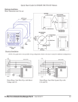
1
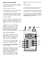
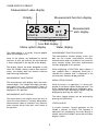
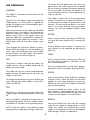
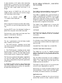
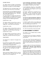
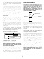
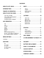
CONTENTS
HOW TO GET GOING...................2
UNITS ..........................................9
INTRODUCTION...........................3
TESLA .........................................10
GAUSS........................................10
AMPS/METER .............................10
OERSTED ....................................10
THEORY OF OPERATION ..............3
HOW TO USE THE GM08 .............4
CAPTURE...................................10
THE HALL PROBE .........................4
THE GM08 INSTRUMENT .............4
GM08 LAYOUT.............................4
GM08 DISPLAY FORMAT ..............5
SAVE ON. ...................................10
SAVE OFF ..................................10
RECALL ON ................................11
RECALL OFF................................11
HOLD ON ..................................11
HOLD OFF..................................11
KEY OPERATION..........................6
ON ...............................................6
OFF ..............................................6
ENTER ..........................................6
NEXT............................................6
MENU ..........................................6
RANGE .........................................6
RESET ...........................................7
HALL PROBE BUTTON ..................7
RS232, USB SERIAL INTERFACE.....7
DC POWER SUPPLY SOCKET ........8
UTILITIES...................................11
NULL ..........................................11
AUTO ZERO ...............................11
POWER DOWN ..........................12
LANGUAGES...............................12
HALL PROBE..............................12
MENU OPTIONS...........................8
AC MEASUREMENT ACCURACY .12
GENERAL ..........................................8
FUNCTION ...................................8
POLARITY..................................13
DC ...............................................8
DC PEAK.......................................8
AC RMS........................................9
AC RMS MAX ...............................9
AC PEAK .......................................9
BATTERY REPLACEMENT ...........13
USING A GAUSSMETER..............13
ANALOG OUTPUT......................14
SPECIFICATION ..........................15
COMPANY ADDRESS .................16
1
HOW TO GET GOING
The GM08 is designed to be easy to use and
assumes you never get as far as reading this let
alone the rest of the manual.
So this is how to get going:
1. Insert the batteries
2. Plug in the probe
3. Press the ON key
4. Wait while the GM08 carries out self calibration (10 seconds approximately).
5. When the GM08 completes it’s self calibration
it will enter into the mode of operation last
used.
6. If you want to change something, press the
MENU key to display the first menu Option.
To look at different Menu options, press the
NEXT key to cycle through the Options until
you find what you are looking for. Then press
ENTER.
7. Press MENU key again to clear the Menu line
of the display.
8. Press MENU key again to display the main
Menu Option back at the first Option.
9. Change Measurement ranges with the Range
key.
If you want to do more adventurous things you
could always try reading the rest of the manual!
HINT
When changing and selecting Menu Options,
hold the GM08 with both hands with your
thumbs over the ENTER and NEXT keys. This will
enable you to easily and rapidly change settings.
PLEASE NOTE
The Transverse and Axial Hall probes supplied for
use with the GM08 Hand Held Gaussmeter are
very robust compared to the previous generation
of Hall Probes.
It should be noted, however, that without due
care these probes can be irreparably damaged
due to bad handling and incorrect use.
Operators are advised to take due care.
2
INTRODUCTION
In reality, all practical Hall Probe elements are
only linear within certain limits, normally 1% 2%.
Congratulations on choosing the GM08 the latest in a family of Gaussmeters by Hirst Magnetic
Instruments Ltd, with more than 30 years experience in manufacturing Magnetic Instruments and
Magnetic Equipment.
The more accurate and thinner the probes, the
greater the expense. Most Gaussmeter manufacturers approach this problem by selecting current
and Hall Probe load resistance to minimise these
non-linearity errors.
The GM08 incorporates many innovative functions and new features.
The Hall Probes are connected to Gaussmeters,
the Gaussmeters are designed to be linear to
makethe best use of the non-linear Hall Probes.
All GM08 Probes are compatible with the GM08
without the need for re-calibration by the operator.
The philosophy behind the design of the GM08
is that both the Probe and the Gaussmeter will
contain non-linearities and errors. The difference
between a theoretical, perfect Hall Probe and
that of an individual Hall Probe is measured and
the difference recorded in an E2prom located in
the Hall probe socket (this memory device also
contains other information such as serial number
and calibration date).
Each GM08 Probe contains information unique
to that Probe which enables the GM08 to carry
out automatic calibration at switch on and Auto
Zero (see Utilities).
The GM08 incorporates a 120 by 32 pixel graphic menu driven display. This enables operation of
the GM08 to be carried out simply with a minimal number of keys and with minimal training.
The perfect Hall Probe is in fact a calibration
process using a technique known as Nuclear
Magnetic Resonance (NMR) which gives very
high accuracy.
The GM08 incorporates an RS232, USB interface,
analog interface and external Power Supply Unit
(PSU) socket.
The errors between the GM08 and an ideal electronic circuit are measured and recorded in it’s
internal E2prom.
The GM08 Hall Probe includes a button for Probe
orientation (Transverse Probes) and HOLD for
Saving readings.
When a measurement is taken the voltage generated by the Hall Probe element is amplified by
the GM08 electronic circuit and digitised in an
Analogue to Digital convertor.
The Transverse and Axial Hall probes supplied for
use with the GM08 Hand Held Gaussmeter are
very robust compared to the previous generation
of Hall Probes.
The software of the GM08 then automatically
corrects this data mathematically, firstly with the
Hall Probe calibration information and then with
the GM08 calibration information.This technique
gives superb results and enables calibration of the
Gaussmeter to be carried out in software rather
than “select on test” resistor values.
It should be noted, however, that without due
care these probes can be irreparably damaged
due to bad handling and incorrect use.
Operators are advised to take due care.
THEORY OF OPERATION
The GM08 includes other innovative techniques
which further improve and give additional long
term stability.The GM08 also includes a linear
analogue circuit for peak detection. This dedicated circuit enablesthe accurate capture of transient events without the inherent delays of
Analogue to Digital Convertor sampling times.
Hall Effect Theory
In an ideal world, a Hall Element consists of a
small slab of semi-conductor material. Current
passes from one end of the slab to the other and
the voltage on each edge of the slab is the same
when no magnetic field is present. If a magnetic
field is now applied through the top to bottom
surfaces of the slab, a voltage appears across the
sides of the slab which is directly proportional to
the Magnetic Flux Density or Magnetic Field
Strength.
3
Although this captured voltage level will decay, in
the analogue circuit, it is converted and displayed
from a digital storage giving zero droop digital
storage.
HOW TO USE THE GM08
frequently used Options being the quickest to
access.
The GM08 Hand Held Gaussmeter and Probe is
used to measure Magnetic Flux Density or
Magnetic Field Strength.
GM08 LAYOUT
There are two parts to the GM08:
The GM08 Hand-Held Gaussmeter consists of a
main hand-held unit and Hall Effect Probe.
1. The Probe that actually senses the Magnetic
Field and produces an electrical signal.
The main Hand-Held unit consists of a 120 by 32
pixel graphic LCD, 7 keys and Hall Probe socket.
2. The GM08 Instrument itself, that then processes these electrical signals to display actual measurements that the user can read off the display.
This manual gives information on the operation
of the various parts of the GM08. This GM08 layout diagram will give you quick access to the
appropriate page of this Manual.
THE HALL PROBE
The sensitive part of the Hall Probe (the Hall
Element), is placed into a Magnetic Field. The
Hall Element must be at right angles to the
Magnetic lines of Flux to give a maximum reading.
In practise, this is a case of placing a
Transverse Probe into an air gap
between two magnetic poles and
adjusting it to give a maximum reading, or placing an Axial Probe into the
centre of a solenoid and adjusting its
position to give a maximum reading.
Page 7
Page 7
THE GM08 INSTRUMENT
The Hall Probe is plugged into the Hall
Probe connector at the top of the
GM08. The measured magnetic field
and other necessary information, is
shown on the Liquid Crystal Display.
The various keys on the GM08 enable
you to turn on and off the GM08,
change ranges and control the Menu.
The majority of functions and facilities
within the GM08 is controlled through
an easy to use menu.
Page 5
Page 6
Page 6
Page 6
Page 6
Page 6
Page 7
Page 6
By pressing the MENU key, the first
Menu Option is displayed. By pressing
the NEXT key, the next Menu Option is
displayed. Pressing the ENTER key will
allow you to enter that Option.
In this way, the Operator can quickly
change measurement units or function
etc in the Gaussmeter with the most
4
GM08 DISPLAY FORMAT
Measurement value display
Polarity
Measurement function display
25.36
Units
mT
Measurement
units display
HOLD
Fixed Range
Low Batt display
Status display
Menu option display
The GM08 display is a 120 by 32 pixel graphic
liquid crystal display LCD.
MEASUREMENT FUNCTION DISPLAY
The measurement function display shows symbols for the current measurement function.
Measurements taken or recalled in any measurement function always have their measurement
function displayed in this position.
Areas of the display are dedicated to specific
functions so that, for instance, the measurement
is always displayed in the top left of the display.
The display format has been designed so that
when the GM08 is being used to take measurements, the display does not contain irrelevant
and confusing information.
When displaying a FUNCTION Menu Option a
non symbolic form is displayed. When this is
selected the symbolic form is displayed in the
measurement function display position.
MEASUREMENT VALUE DISPLAY
MENU OPTION DISPLAY
The measurement value display shows the measurement digits. This includes four digits, plus decimal point and sign. Measurements taken or
recalled in any measurement function are alwaysdisplayed in this position.
When the menu is in operation, it is always displayed in the Menu Option display position. The
Menu Option displayed can be selected by pressing the ENTER key. Alternative Options may be
displayed by pressing the NEXT key.
MEASUREMENT UNITS DISPLAY
The Menu Option display can be activated by
pressing the MENU key.
The measurement units display shows the units in
which the measurement is currently being taken.
Measurements taken or recalled in any measurement function always have their units shown in
this position.
STATUS DISPLAY
In certain functions, normal operation of the
GM08 is altered, ie HOLD. The Operator is
advised of this condition by the status display. If
normal status of the GM08 is active then the status
display is blank.
5
KEY OPERATION
To remove the Hall probe from the meter, first
power down the meter and remove the probe.
Do not remove the probe with power applied as
this may possibly cause data corruption of the
internal memory and the current operating settings may be lost.
GENERAL
The GM08 is switched on and off with the ON
and OFF keys.
The GM08 is fitted with an Auto power-down
facility. If a button has not been pressed for 1, 4
or 10 minutes the GM08 will power-down automatically. The time for power-down is user selectable in the menu and the auto power-down
function can also be disabled (Utilities Menu
Option).
With USB or a DC power supply connected the
GM08 powers on when power is applied.The
Range is changed or set to Auto Range by pressing the Range button.
Most of the functions of the GM08 are controlled
through an easy to use Menu. Cycle through the
Menu to choose your Option. The Menu is displayed, always with its first Option when you
press the MENU key. If the MENU is already displayed, pressing the MENU key removes it. Press
MENU again and the first Menu Option reappears.
ENTER
When using the Menu, pressing the ENTER key
will select the Menu Option that is currently displayed.
When a different Menu option is required, the
next Option can be displayed by pressing the
NEXT key.
Cycle through the four Menu Options by pressing the NEXT key. When you see the Option you
want - press the ENTER key then cycle through
the new Options with NEXT again. The frequently used Options are quickest to get to.
NEXT
ON
When using the Menu, pressing the NEXT key
will show the next option in the Menu or submenu to be displayed.
The ON key is used to switch on the GM08. The
GM08 turns on with an audible bleep and the
display will show GM08.
When the required Menu or Sub Menu option is
displayed it can be selected by pressing ENTER.
The GM08 will carry out a self test and calibration
before entering the operating set up when the
GM08 was last used.
MENU
To change the operating set up, press MENU and
move through the Menu options using NEXT.
Select with ENTER.
Most of the functions of the GM08 are controlled
through a Menu. When the Menu or Sub Menu
options are not being displayed, pressing the
MENU key will cause the first option in the main
Menu to be displayed.
OFF
Pressing the MENU key when a Menu or Sub
Menu option is being displayed will clear the
Menu line. Pressing the MENU key again will now
reinstate the first option in the main Menu.
The OFF key is used to switch off the GM08. The
GM08 will give an audible bleep before switching
off.
RANGE
When the GM08 is switched off it stores the current operating settings. When the GM08 is againswitched on it will return to this operating set up.
Pressing the RANGE key will cause the working
range of the GM08 to change.When in AUTO
range, the GM08 will automatically change
ranges as the Magnetic Flux Density or Magnetic
Field Strength increases and decreases.
NOTE: When the GM08 is switched off all stored
readings (but not operating settings) will be lost.
6
In some functions, ie DC peak, when measuring
pulsed fields, it is necessary to use manual ranges.
Pressing the RANGE key will cause the GM08 to
leave the Auto range mode and enter a set
Range.
RS232 SERIAL INTERFACE , USB INTERFACE (GM08)
Further presses of RANGE key will cause the
GM08 to enter successively less sensitive ranges
until returning to Auto range.
The GM08 can be controlled by, and can upload
data through the RS232 and USB interfaces.
When in a manual range
“O”symbol will be displayed.
GENERAL
The GM08 is supplied with a serial connector to
enable a standard NULL MODEM 9 way D type
cable to be connected, from a PC, to the GM08.
Along with a USB port for USB connection. Using
a USB A to MINI B type lead. Batteries must still
be fitted whilst using the USB interface.
●
RESET
When using the DC Peak or AC RMS MAX modes,
it is necessary to reset the display between readings.
The GM08 is also supplied with a cd rom disk
with basic PC compatible software and documentation.
Pressing RESET resets the displayed reading to
permit the next peak value to be measured.
SOFTWARE
The Reset key is also used in Null and Auto Zero
Options in the Utilities Sub-Menu.
Instructions for using the Software are on the cd
rom, read the readme.txt file for installation
instructions.
HALL PROBE BUTTON
Software Installation
This key is positioned on the Hall Probe handle
and is used for two functions:
If in Windows insert GM08 Communications disk
in cd rom drive and then follow the simple instructions to install.
1. The HOLD function - Readings can be held
with a press of the Hall Probe button and released
with a second press.
CONNECTING THE GM08 TO A COMPUTER
Interface and Cable Connections
2. The STORE function - Readings can be stored
by pressing the Hall Probe button (only when the
store function is active). The Hall Probe button
can be made inactive. (Capture Menu Option).
The GM08 has a 9 way ‘D’ shaped connector
(port) at the top of the unit. You will need a NULL
modem cable with a 9 way female end for the
GM08 port.
The Transverse and Axial Hall probes supplied for
use with the GM08 Hand Held Gaussmeter are
very robust compared to the previous generation
of Hall Probes.
You will need to purchase or have available a
cable with a 9 way connector at one end (RS232
Cable.) This cable plugs into the top of the
GM08 and then off to the PC.
It should be noted, however, that without due
care these probes can be irreparably damaged
due to bad handling and incorrect use. Operators
are advised to take due care.
The choice of either 9 way or 25 way connection
at the PC end is dependent on your PC.
Alternatively use a USB A to MINI B cable for USB
communications. If both serial and USB cables
are fitted, serial communications are disabled.
Application notes
The programs included on the cd are for basic
control and transfer of data. Optional software
7
The socket is a standard 2.1mm DC power supply socket with the positive to centre, negative to
shell. The GM08 will require a voltage supply
between +5V and + 6V DC.
and advanced information on the serial protocol
is available to allow the user to write custom
software on windows and unix platforms.
It is important that you connect the Serial Cable
/ USB cable between the GM08 and your PC,
BEFORE running these programs. Failure to do so
will not damage the GM08.
This input is protected from supply reversals to
avoid damage to the GM08 if the input voltage is
reversed.
Windows 95-98, 2000 XP Users
MENU OPTIONS
Follow the instructions in the readme.txt file on
the enclosed cd rom.
GENERAL
SERIAL INTERFACE UNIT
Most of the functions of the GM08 are controlled
through the Menu. (Range and Reset Control
have their own keys).
As previously supplied on GM05.
There is no separate conditioner (level shifter) for
the RS232 port on the GM08. The GM08 can be
directly connected to the RS232 port of the computer via a NULL modem cable.
Each main Menu Option has its own Sub-Menu.
MENU OPTION
FUNCTION
PIN ASSIGNMENTS - 9 WAY CONNECTOR GM08 sidePin
Description
2
Received data (input to GM08)
3
Transmit data (output from GM08)
7
Active RS232 level (output from GM08)
5
Signal Ground
6
CTS (Assumed Active)
ALL OTHER PINS ARE NOT CONNECTED
DC, DC Peak, AC RMS, AC RMS MAX and AC
Peak.
When the FUNCTION option is displayed and the
ENTER key is pressed, the GM08 will enter the
FUNCTION SUB MENU and display the first suboption.
The active level on Pin 7 can be used to tie any
hardware handshaking lines active, this is
required on some machines. The GM08 serial
protocol does not support handshaking, therefore any hardware handshaking on the host
machine MUST BE DISABLED.
Pressing NEXT will enable the user to move
through the options available. The DC function
measures Magnetic flux density or Magnetic field
strength of a static or DC Magnetic field.
Pressing ENTER will select the displayed SubMenu Option.
COMMUNICATION SETTINGS FOR GM08 RS232
INTERFACE
FUNCTION SUB-MENU OPTIONS
9600 Baud, 8 data bits, 1 stop bit, no parity.NO
damage will occur if the GM08 is turned off
whilst the host machine is on.
DC
DC POWER SUPPLY SOCKET (GM08)
This function measures Magnetic flux density or
Magnetic field strength of a static or DC
Magnetic field.This reading is updated as the
static Magnetic field varies.
The GM08 is fitted with a 2.1mm external power
supply socket. This enables a DC Power Supply
Unit (PSU) (not supplied) to be used with the
GM08.
DC PEAK
Batteries must still be fitted in the unit. However,
only a small amount of current will be drawn
from the batteries for memory retention.
This function measures the peak positive DC
Magnetic Flux density or Magnetic Field
Strength.
8
This reading is updated with increasing measurements. Once a maximum measurement has been
reached this value will be held until the RESET key
is pressed.
This reading is updated with increasing measurements. Once a maximum measurement has been
reached this value will be held until the RESET key
is pressed. This reading is held digitally and will
not decay and can be held indefinitely.
This reading is held digitally and will not decay
and can be held indefinitely.
Once a measurement has been made and a new
measurement is required, pressing the RESET keywill reset the displayed value so that a new measurement can be made.
Once a measurement has been made and a new
measurement is required, pressing the RESET keywill reset the displayed value so that a new measurement can be made.
Negative peak values can be measured by inverting the Hall Probe.
AC PEAK
The GM08 captures the peak value with an analogue Peak Detector circuit. This enables fast
transients to be captured and is not dependent
upon the conversion rate of the Analogue to
Digital Convertor circuit. This technique enables
fast transients to be captured but without the
normal decay of the captured value.This function
can be used for capturing transient Magnetic
fields such as in Capacitive Discharge
Magnetisers.
This function measures the positive peak value of
a time varying AC magnetic field. Negative peak
values can be measured by reversing the probe.
This function is a true Peak measurement and
does include any DC components of the magnetic field. The AC Peak reading is a continuously updated measurement.
MENU OPTION
* Warning - This facility is designed to be sensitive and respond rapidly. It is possible that in electrically noisy environments spurious readings can
be achieved. Care should be taken.
UNITS
Tesla, kA/m, Gauss, Oersted.
Measurements on Capacitive Discharge
Magnetisers using Ignitrons may give off such
electrical noise.
When the UNITS option is displayed and the
ENTER key is pressed the GM08 will display the
UNITS sub-menu.
AC RMS
Pressing NEXT will enable the user to move
through the Sub-Menu options.
This function measures the true RMS (Root Mean
Square) of an AC Magnetic field.
Pressing ENTER will select the displayed SubMenu option.
The measurement is a true RMS measurement
but does not include any DC components of
theMagnetic field which may be present.
Magnetic Flux Density is measured in Tesla (T),
and milliTesla (mT) in the SI measurement system
and Gauss (G) and kiloGauss (KG) in c.g.s. measurement system.
The RMS value displayed is not dependent upon
the crest factor limits. This measurement is continuously updated.
Magnetic Field Strength is measured in
kiloAmperes per meter (kAmp/m) in the SI system and Oersted (Oe) and kiloOersteds (kOe) in
the c.g.s system.
AC RMS MAX
This function measures the maximum true RMS
of an AC Magnetic field.
The measurement is a true RMS maximum but
does not include any DC components of the
Magnetic field which may be present.
9
UNITS SUB-MENU OPTIONS
ENTER key is pressed, the GM08 will display the
CAPTURE sub menu.
TESLA
This sub menu enables the user to set up the
GM08 to SAVE and RECALL from 00-99 samples,
or HOLD the current measurement reading.
This function enables the GM08 to measure
Magnetic flux density in units of Tesla (T) and
milliTesla (mT) the standard unit of Magnetic
flux density in the SI system.
The samples are stored with full resolution, units
and measurement function.
The measurements taken will be displayed in
Tesla (T) or milliTesla (mT) depending upon the
operating range.
SAVE, RECALL and HOLD functions are mutually
exclusive, that is, only one of these functions
canbe operated at any one time. All options can
be selected off.
GAUSS
Any readings stores are retained even after
power-down, in non volatile RAM. Stored readings this retained are only cleared suing the
“SAVE ON” OPTION IN THE capture MENU.
This function enables the GM08 to measure
Magnetic flux density in units of Gauss (G) and
kiloGauss (kG) the standard unit of Magnetic flux
density in the c.g.s system.
Samples are Time and Date stamped. This is only
accessible through the RS232 and is uploaded
with the register data when the GMLOAD program is used.
The measurements taken will be displayed in
Gauss (G) or kiloGauss (kG) depending upon theoperating range.
CAPTURE SUB-MENU OPTIONS
AMPS/METER
SAVE ON
This function enables the GM08 to measure
Magnetic Field Strength in units of kiloAmperes
per meter (kA/m) the standard unit of Magnetic
field strength in the SI system.
This option enables the GM08 operation to Save
measured values in memory locations within the
GM08.
The measurements taken will be displayed in
kiloAmperes (kA/m).
The display will show R followed by a two digit
number. Pressing the Hall Probe button will now
Save the current measurement in a register. The
display will show the Register number of the last
stored value, ie R15 (or Register No 15).
OERSTED
This function enables the GM08 to measure
Magnetic field strength in units of Oersted (Oe)
and kiloOersted (k/Oe) the standard unit of
Magnetic field strength in the c.g.s system.
Samples are saved with full resolution, units and
measurement function.Selecting Save On will
automatically activate Recall Off.
The measurements taken will be displayed in
Oersted (Oe) or kiloOersted (k/Oe) depending
upon the operating range.
SAVE OFF
This returns the GM08 to normal operation and
terminates the Save operation.
MENU OPTION
If Save On is re-entered then measurements are
saved in the next available location unless Recall
has been used, in which case Save data is overwritten. Save Off function is automatic when
Recall On is selected.
CAPTURE
Store On, Store Off, Recall On, Recall Off, Hold
On, Hold Off.
When the CAPTURE option is displayed and the
10
RECALL ON
When a reading is being held it is possible to
change units using the Menu Option and the
reading will automatically be converted using the
Units Menu Option.
This Option enables the GM08 operation to enter
the RECALL Sub Menu Option which enables the
GM08 to recall measured values stored in memory locations using the SAVE Option.
HOLD OFF
The display will show R followed by a two digit
number ie R15 (Recall Register 15).
The HOLD function can be disabled with the
HOLD OFF Option in the STORE Sub Menu.
Readings can be saved in one unit and recalled in
another - ie saved in Gauss and recalled in Tesla,
with conversions taking place automatically.
The HOLD function will not operate when the
SAVE Option or RECALL Option is in operation.
MENU OPTION
On leaving SAVE or RECALL functions the stored
values will be retained. If the GM08 is switched
off all saved measurements will be lost.
UTILITIES
Null, Auto Zero, Auto Power-Down, Languages.
After Recall On has been selected (Entered), any
further Saved values will be saved from Register
00. Selecting Recall On will automatically activate
Save Off.
When the UTILITIES option is displayed and the
ENTER key is pressed, the GM08 will display the
UTILITIES sub menu.This Sub-Menu contains a
number of lesser used options.
RECALL ON SUB-MENU OPTION
UTILITIES SUB-MENU OPTIONS
FIRST
NULL
This Option enables the GM08 to recall measurement R00.
This Option enables the Operator to quickly Null
(Zero) the GM08 and Hall Probe for all ranges of
the current Measurement Function.
NEXT
This option enables the GM08 to recall the next
measured value (ie if R00 was displayed, entering
NEXT will recall measurement R01). This should
not be confused with the NEXT key which is used
as normal.
When this Option has been selected the Operator
is instructed to place the Hall Probe in the Zero
Flux Chamber and press RESET. The GM08 then
takes approximately 4 seconds to carry out this
Null Function.
RECALL OFF
This Option would only normally be used when
sensitive readings are to be taken.
This returns the GM08 to normal operation.This
terminates the RECALL operation. Selecting Save
On will automatically activate Recall Off.
AUTO ZERO
HOLD ON
This option carries out an automatic re-calibration procedure on the GM08, this includes a Null
function automatically. This process will take
approximately 30 seconds.
When this option has been selected, measurement readings can be held by pressing the Hall
Probe button once.
This process should be carried out when the
GM08 has not been used for long periods or at
other times when the Operator wishes.
The status display will show HOLD.The measurement reading can be released by pressing the
Hall Probe button again. The status display will
no longer show HOLD.
11
POWER DOWN
In most applications, measurements need to be
taken in an air gap where side entry is available.
For this type of application a Transverse Probe is
used (supplied as standard with the GM08).
This option enables the GM08 to automatically
power down 1,4 or 10 minutes after the last key
was pressed. This Option can also be disabled.
In some applications side entry is not available,
such as measuring the field inside a Solenoid. In
this application, Axial Probes can be used
(optional accessory).
The Operator will see a warning message 5 seconds before Auto Power-Down will take place.
Auto Power-Down can be delayed by pressing
any of the keys (except ON or OFF), including the
Hall Probe button.POWER DOWN SUB-MENU
OPTIONSPOWER DOWN OFF
The GM08 is supplied with a standard Transverse
Hall Probe. The thin semi-flexible Hall Probe
incorporates a Gallium Arsenide Hall Element
which is encapsulated to make it resistant to
damage.
This option disables the GM08 from automatically powering down. The GM08 will only turn off
with the Operator pressing OFF key, the battery
expiring, or the USB cable being removed.
The Transverse and Axial Hall probes supplied for
use with the GM08 Hand Held Gaussmeter are
very robust compared to the previous generation
of Hall Probes.
POWER DOWN 1 MIN
It should be noted, however, that without due
care these probes can be irreparably damaged
due to bad handling and incorrect use.
This Option enables the Power-Down routine of
the GM08 to automatically Power-Down the
GM08 after 1 minute from the last key press.
Operators are advised to take due care.Do not
disconnect the Hall Probe whilst the meter is ON.
POWER DOWN 4 MIN
This Option enables the Power-Down routine of
the GM08 to automatically Power-Down the
GM08 after 4 minutes from the last key press.
Turn OFF the meter before removing the probe.
AC MEASUREMENT ACCURACY
POWER DOWN 10 MIN
The GM08 has two standard Probes available.
Transverse and Axial.
This Option enables the Power-Down routine of
the GM08 to automatically Power-Down the
GM08 after 10 minutes from the last key press.
The GM08 and Transverse Probes are supplied in
a calibrated form to give excellent DC and AC
measurements.
LANGUAGES
In the case of the Transverse probe only, this
assumes that the AC measurement is applied only
to the Hall Probe element at the end of the Hall
Probe (as when measuring AC flux density in air
gaps).
The GM08 Menu can operate in languages other
than English.
By entering the Language Option of the Utilities
Sub-Menu, the operator can use the NEXT key to
cycle through the Language Options.
In order to supply a thin Transverse Hall probe at
reasonable cost, the Hall Probe construction
includes what is effectively a small single turn
inductive loop running the length of the Hall
probe flexible section.
To select the required language press the ENTER
key. The menu will then operate in that selected
language even after switching off the GM08.
HALL PROBE
When the whole length of the Transverse probe is
exposed to an AC field errors can accumulate due
to pick up in this inductive loop. These errors are
dependent upon the flux linkage through the
loop (ie the length of probe exposed to the field)
When measuring a Magnetic Field, the sensitive
Hall Element within the Probe must be at right
angles to the lines of Magnetic Flux.
12
and the frequency of the alternating field being
measured. The greater the frequency the greater
the error.
USING A GAUSSMETER
Hall Probe measurements of magnetic flux density (measured in Tesla or Gauss) or Magnetic fieldstrength (Amp/meter or Oersted) are ideal in
applications with parallel fields such as air
gaps.The field will be uniform across the air gap
and small movements of the probe will give rise
to only small changes in readings.
It is therefore recommended when measuring AC
fields in the centre of an air-cored solenoid orsimilar, that an Axial Probe which does not suffer
from the effects, is used in preference for both
accuracy and physical suitability.
The Transverse probe will not include significant
errors when the Hall Probe tip only is subjected to
the alternating field.
Probe Sensor Area
S
POLARITY
N
The polarity of a measurement in DC is: DC peak
and AC peak readings are positive readings only.
Negative readings can be taken by reversing the
probe.
The Transverse and Axial Hall probes supplied for
use with the GM08 Hand Held Gaussmeter are
very robust compared to the previous generation
of Hall Probes.
The transverse Hall probe should be positioned in
the air gap and angled to give the maximum
reading.
If the Hall probe is not at right angles to the magnetic flux a less than maximum reading will be
obtained.
It should be noted, however, that without due
care these probes can be irreparably damaged
due to bad handling and incorrect use.
The Hall probe should then be moved around
searching for the maximum reading.
Operators are advised to take due care.
S
It should be remembered that this is a maximum
reading for one point only. Typical values
throughout the air gap may be several % lower.
N
Axial Probe
N
S
Hall Probe
Uniform Field
Transverse Probe
In many applications a measurement of a permanent magnet is required. The magnet is not in
any form of magnetic circuit and may need to be
inspected at (say) goods inwards.
POSITIVE READINGS
BATTERY REPLACEMENT
A Hall probe is often used in this type of application and in some cases a Hall probe technique
may be stipulated in a specification.
When the batteries have expired it will be necessary to replace them. Firstly, switch off the GM08
and disconnect the Hall Probe.
Such measurement should be used as a guide
only and not as an absolute measurement. Two
perfectly calibrated gaussmeters can be used for
such a measurement and show significantly different readings.
Remove screw from battery door and remove
cover. Remove old batteries and replace. Replace
battery compartment door and replace screw.
THE STATUS DISPLAY WILL SHOW A BATTERY
SYMBOL WHEN THE BATTERY VOLTAGE IS LOW.
13
Probe Sensor Area
Hall Probe
Diverging Lines
of Flux
N
S
When a magnet, particularly with a small face, is
not in a magnetic circuit - the magnetic flux lines
will radiate and diverge. Therefore, as the Hall
probe is moved closer to the surface of the magnet, the resultant reading will increase. When the
probe is in contact with the surface of the magnet, the active area of the probe remains at a distance from the magnet surface due to the probe
wall thickness. This is small but finite.
The next probe will have a different thickness of
wall and a different reading for the same magnet.
This is why a probe can be turned over and
instead of a negative reading of the same value
being given, something significantly different can
be shown.
Provided that this is taken into account the Hall
probes can be used to give a good guide to good
and bad parts - but not an absolute measurement.
An absolute measurement for an “Open Circuit”
magnet, involves using an Integrated Fluxmeter.
It should be noted that in recent years some suppliers of Hall effect gaussmeters have been advertising them as “Fluxmeters”, this is incorrect.
Fluxmeters are used in conjunction with a coil to
take direct measurements of flux rather than flux
density.
Analog Output
The analog output is +/- 3 volts fullscale. Input
impedances of attached device should be greater
than 100 k Ohms.
14
SPECIFICATION
Range 1
Range 2
0 - 3 Tesla
resolution 1 milliTesla
Range 3
0 - 29.99 milliTesla
resolution 10 microTesla
0 - 30 kGauss (kiloOersted)
resolution 10 Gauss (Oersted)
0 - 299.9 Gauss (kiloOersted)
resolution 0.1 Gauss (Oersted)
0 - 2387 kiloAmps/m
resolution 80 kiloAmps/m
0 - 23.87 kiloAmps/m
resolution 800 Amps/m
0 - 299.9 milliTesla
resolution 100 microTesla
Range 4
0 - 2.999 milliTesla
resolution 2 microTesla
0 - 2.999 kGauss (kiloOersted)
resolution 1 Gauss (Oersted)
0 - 29.99 Gauss (kiloOersted)
resolution 0.02 Gauss (Oersted)
0 - 238.7 kiloAmps/m
resolution 8 kiloAmps/m
0 - 2.39 kiloAmps/m
resolution 160 Amps/m
(1mT = 10 Gauss = 0.796 kA/m)
Accuracy (at 20oC)
Reproducibility
Temperature Coefficient
Frequency Range
Averaging Time Constant
Operating Temp. Range
Storage Temp Range
Power Supply
Battery Type
Battery Life
Better than ±1% (DC)
Traceable to NPL Standards
Better than 0.5%.
±0.1% of reading/oC including probe
DC and 15Hz to 10kHz
100 milliseconds
0oC to + 50oC
- 20oC to + 70oC
4 x 1.5V, AA Alkaline battery or external
power supply +5V to +6V (not supplied)
1.5V AA Alkaline Long life (not supplied)
15 Hours continuous operation. Auto power-down after 1,4 or 10
minutes or disabled all under menu control
120 by 32 pixel graphic LCD
3 sec approx
DC, DC Peak, AC RMS, AC RMS MAX, AC PEAK
Store and Recall on 0-99 samples
Display
Display Sampling Rate
Functions
Facilities
Hold facility
Analogue Peak with digital storage
Analogue Output
+/- 3 Volts full scale
USB
1.1 Compliant
Auto and manual ranges
Automatic reading conversion between different units
Operating set up at time of power-down is stored and recalled automatically at power-on
Utilities etc.
Time Keeping device
GM08 Meter Only
Volatile Memory
Dimensions
Length
175mm
Width
90mm
Height
43mm
Weight (inc battery)
400g approx (not including probe)
Standard Accessories
Transverse Hall Probe, Zero Flux Chamber, USB cable, BNC adaptor,
Communications Software for IMB PC and Carrying Case
Optional Accessories
Axial Probe Ref AP002
Replacement Transverse Probe Ref TP002.
Reference Magnets Axial and Transverse - contact factory for details
15
HALL PROBES
Transverse Probe
Thickness 1mm
Width 4mm
Length 90mm (not including handle)
Length 230mm (including handle)
Hall sensor active area 0.2mm X 0.2mm approx
Cable length 1.5m
Supplied as standard with the GM08
Extra Probe Ref TP002
Axial Probe
Diameter 5mm
Length 90mm (not including handle)
Length 230mm (including handle)
Hall sensor active area 0.2mm X 0.2mm approx
Cable length 1.5m
(Optional accessories) Ref AP002
The Transverse and Axial Hall probes supplied for use with the GM08 Hand Held Gaussmeter are very
robust compared to the previous generation of Hall Probes.
It should be noted, however, that without due care these probes can be irreparably damaged due to bad
handling and incorrect use.
Operators are advised to take due care.
This product complies with the Low Voltage Directive (LVD) and Electromagnetic Compatibility
(EMC) directive.
COMPANY ADDRESS
Hirst Magnetic Instruments Ltd
Tesla House
Tregoniggie Industrial Estate
Falmouth
Cornwall
TR11 4SN
United Kingdom
Tel:
Fax:
01326 372734
01326 378069
Email: [email protected]
Website: www.hirst-magnetics.com
16