1
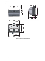
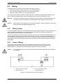
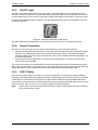
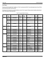
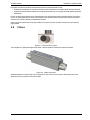
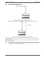
ICAM IAS-1
Product Guide
June 2014
Document Number: 16260_03
Part Number: 09-00111-10
ICAM by Xtralis
ICAM IAS-1 Product Guide
Intellectual Property and Copyright
This document includes registered and unregistered trademarks. All trademarks displayed are the trademarks of
their respective owners. Your use of this document does not constitute or create a licence or any other right to use
the name and/or trademark and/or label.
This document is subject to copyright owned by Xtralis AG (“Xtralis”). You agree not to copy, communicate to the
public, adapt, distribute, transfer, sell, modify or publish any contents of this document without the express prior
written consent of Xtralis.
Disclaimer
The contents of this document is provided on an “as is” basis. No representation or warranty (either express or
implied) is made as to the completeness, accuracy or reliability of the contents of this document. The manufacturer
reserves the right to change designs or specifications without obligation and without further notice. Except as
otherwise provided, all warranties, express or implied, including without limitation any implied warranties of
merchantability and fitness for a particular purpose are expressly excluded.
General Warning
This product must only be installed, configured and used strictly in accordance with the General Terms and
Conditions, User Manual and product documents available from Xtralis. All proper health and safety precautions
must be taken during the installation, commissioning and maintenance of the product. The system should not be
connected to a power source until all the components have been installed. Proper safety precautions must be taken
during tests and maintenance of the products when these are still connected to the power source. Failure to do so
or tampering with the electronics inside the products can result in an electric shock causing injury or death and may
cause equipment damage. Xtralis is not responsible and cannot be held accountable for any liability that may arise
due to improper use of the equipment and/or failure to take proper precautions. Only persons trained through an
Xtralis accredited training course can install, test and maintain the system.
Liability
You agree to install, configure and use the products strictly in accordance with the User Manual and product
documents available from Xtralis.
Xtralis is not liable to you or any other person for incidental, indirect, or consequential loss, expense or damages of
any kind including without limitation, loss of business, loss of profits or loss of data arising out of your use of the
products. Without limiting this general disclaimer the following specific warnings and disclaimers also apply:
Fitness for Purpose
You agree that you have been provided with a reasonable opportunity to appraise the products and have made
your own independent assessment of the fitness or suitability of the products for your purpose. You acknowledge
that you have not relied on any oral or written information, representation or advice given by or on behalf of Xtralis
or its representatives.
Total Liability
To the fullest extent permitted by law that any limitation or exclusion cannot apply, the total liability of Xtralis in
relation to the products is limited to:
i. in the case of services, the cost of having the services supplied again; or
ii. in the case of goods, the lowest cost of replacing the goods, acquiring equivalent goods or having the goods
repaired.
Indemnification
You agree to fully indemnify and hold Xtralis harmless for any claim, cost, demand or damage (including legal costs
on a full indemnity basis) incurred or which may be incurred arising from your use of the products.
Miscellaneous
If any provision outlined above is found to be invalid or unenforceable by a court of law, such invalidity or
unenforceability will not affect the remainder which will continue in full force and effect. All rights not expressly
granted are reserved.
www.xtralis.com
i
ICAM IAS-1 Product Guide
ICAM by Xtralis
Document Conventions
The following typographic conventions are used in this document:
Convention Description
Bold
Used to denote: emphasis.
Used for names of menus, menu options, toolbar buttons
Italics
Used to denote: references to other parts of this document or other
documents. Used for the result of an action.
The following icons are used in this document:
Convention Description
Caution: This icon is used to indicate that there is a danger to
equipment. The danger could be loss of data, physical damage, or
permanent corruption of configuration details.
Warning: This icon is used to indicate that there is a danger of electric
shock. This may lead to death or permanent injury.
Warning: This icon is used to indicate that there is a danger of inhaling
dangerous substances. This may lead to death or permanent injury.
Contact Us
Europe, Middle East & Africa
+44 1442 242 330
D-A-CH
+49 431 23284 1
The Americas
+1 781 740 2223
Asia
+86 21 5240 0077
Australia and New Zealand
+61 3 9936 7000
www.xtralis.com
Product Listings
l
l
EN 54-20 (VdS) (Sensitivity Class dependant upon point detector used)
CE Mark
Regional approvals listings and regulatory compliance vary between ICAM product models. Refer to
www.xtralis.com for the latest product approvals matrix.
Document: 16260_03
Part Number: 09-00111-10
ii
www.xtralis.com
ICAM by Xtralis
ICAM IAS-1 Product Guide
Table of Contents
1
Introduction
3
2
Detector Installation
5
2.1
2.2
2.3
3
4
5
6
Mounting the Detector Enclosure
Wiring
Point Detectors
6
8
10
Pipe Network Installation
17
3.1
3.2
3.3
3.4
3.5
3.6
3.7
3.8
3.9
17
17
17
18
18
18
18
19
20
Pipe Specification
Fixings
Sampling Holes
End Cap
Bends
Capillary Tubes
Exhaust
Filters
Open Area Applications
Configuration
21
4.1
4.2
4.3
21
22
23
Display Functions
User Interface
Parameters
Testing
25
5.1
5.2
25
25
Point Detectors
System
Maintenance
27
6.1
27
Air Inlet Filter Replacement Procedure
7
Troubleshooting
29
8
Specifications
31
8.1
31
Typical Supply Current & Fan Speed
www.xtralis.com
1
ICAM IAS-1 Product Guide
ICAM by Xtralis
This page is intentionally left blank.
2
www.xtralis.com
ICAM by Xtralis
1
ICAM IAS-1 Product Guide
Introduction
The ICAM IAS-1 system is an aspirating smoke detection system that utilizes an air-sampling pipe network to
draw air towards conventional or analog addressable point detectors in a sealed enclosure.
The single channel IAS-1 detector enclosure (Figure 1-1) has one pipe inlet and provision for one or two point
detectors allowing redundant or double-knock detection. The range of supported point detectors is detailed in
Chapter 2.
Figure 1-1: ICAM IAS-1 Detector Enclosure
Point detectors are wired directly into the signaling circuit connected to the monitoring fire alarm control panel.
Any alarms or faults derived from the analog or conventional point detector will be reported directly to
monitoring fire panel through the signaling circuit for that detector.
The IAS-1 system provides a configurable aspiration system and airflow monitoring. Airflow status is
displayed on a ten element bar graph with adjustments for flow sensitivity and high/low flow thresholds. Flow
faults are indicated on the display interface LEDs and reported to the central panel via isolated volt-free
contacts.
Important Note: Aspirating Smoke Detectors supplied and installed within the EU from June 2013 must
conform to the EU Construction Products Regulation (305/2011/EU-CPR) and the related European
Standard EN 54-20.
This unit has been tested and certified to ensure general conformance to the above directive and
standard but strict adherence to this Product Guide is required to ensure that the installation meets
these requirements in all respects.
An Approvals overlabel must be completed by the installer and applied to the unit at the time of fitting
the point detectors. The label contains the approved CPR CE mark and sensitivity of the detectors
being fitted and MUST be configured in conformance with this document for the installation to be in full
conformance.
Full details of the labeling requirements together with a table of approved detectors and required
sensitivity information are found in Chapter 2.
www.xtralis.com
3
ICAM IAS-1 Product Guide
ICAM by Xtralis
This page is intentionally left blank.
4
www.xtralis.com
ICAM by Xtralis
2
ICAM IAS-1 Product Guide
Detector Installation
The ICAM IAS-1 is provided with the following components:
l
l
l
l
l
l
l
1 detector enclosure
1 corner stud key
1 blanking baffle
1 ferrite core
1 mounting template
1 product guide
Approvals overlabels
Check all components for damage and refer any concerns to your authorized representative.
It is necessary to procure the following additional items:
l
l
l
Point detectors. Refer to Section 2.3.2 on page 10 for further information.
Baffle for the selected point detector. Refer to Section 2.3.1 on page 10 for further information.
Screws and inserts for fixing the unit in place at the installation location.
Legend
B
C
A
Point detector
B
Intake from Pipe Network
C
Airflow
D
Exhaust
A
D
Figure 2-1: Detector Enclosure
www.xtralis.com
5
ICAM IAS-1 Product Guide
2.1
ICAM by Xtralis
Mounting the Detector Enclosure
Notes:
l
l
l
l
l
l
This equipment must be installed by a qualified installer in accordance with all local and national code
requirements.
The detector assembly must be installed at an accessible position to facilitate maintenance and testing.
Ensure that there is sufficient clearance to mount the detector, noting the location of air sampling pipes
and cable entry points. Owing to the rigid nature of the plastic pipe, installation must provide for sufficient
movement in all pipe work (air inlet, air exhaust and cable pipes) to allow pipe ends to be easily fitted and
removed.
Ensure that the exhaust pipe is free from any obstacles at all times.
Do not mount the detector assembly close to a heat source.
Mount the detector assembly in a secure location which is accessible only by authorised personnel.
Mounting Procedure:
1. Remove the transparent cover (D) by using the corner stud key (B) to unscrew the tamper-proof corner
studs (A).
2. Tape the mounting template to the mounting surface and use it to accurately mark the holes
corresponding to the four corner fixing points.
3. Drill four holes in the mounting surface.
4. Remove the mounting template.
5. Secure the detector enclosure to the mounting surface through the four corner fixing points. Use
appropriate fasteners for the type of surface that the unit is mounted on. The diameter of each mounting
hole is 5 mm. Typical No. 8 mounting hardware can be used in the mounting holes.
Legend
A
C
A
Corner Stud
B
Corner Stud Key
C
Screw holes
D
Transparent Cover
B
D
Figure 2-2: Detector Enclosure
6
www.xtralis.com
ICAM by Xtralis
ICAM IAS-1 Product Guide
Dimensions:
29,5mm
37,5mm
188,0mm
49,5mm
183,6mm
140,0mm
32,5mm
165,7mm
241,7mm
183,6mm
166,7mm
129,3mm
159,3mm
258,6mm
Figure 2-3: Detector Enclosure Dimensions
www.xtralis.com
7
ICAM IAS-1 Product Guide
2.2
ICAM by Xtralis
Wiring
The following wiring connections must be made to the detector housing:
l
l
l
24V DC Power Supply. Refer to Section 2.2.3 for further information.
Loop or circuit wiring. Refer to Section 2.2.4 for further information.
Fault Relay. Refer to Section 2.2.5 for further information.
The wiring enters the detector housing via cable seals and is connected to the appropriate terminals on the
main circuit board or display board. The terminals allow wire with a maximum diameter of 2.5mm².
Warning:
To prevent risk of electric shock or possible injury from the rotation of the high performance fan,
the system should be isolated from the power supply when the display board is removed.
Caution:
When installing or servicing the unit, ensure that the operator is safely grounded so as to prevent
electro-static discharge (ESD) damage to the unit.
2.2.1
Wiring Access
For correct operation of the unit it is essential that the case is fully sealed so that air can only be drawn into the
system through the aspirating pipe. Thus, all wiring must pass through the cable seals provided and no
additional holes should be made in the detector housing.
To pass wiring through a cable seal, make a small hole in the centre of the seal with a pointed implement (e.g.
small screwdriver) and then force the cable through the hole into the box. The small hole should expand to
accommodate any cable diameter from 4 to 10 mm. If the seal is not airtight, then it may be necessary to use
a non-reactive resin or glue to create an airtight seal to ensure that air is only drawn through the air sampling
pipe network.
2.2.2
Connect Wiring
To gain access to the terminals on the main circuit board for connection of the wiring, remove the
display/detector mounting board which is held in place by the clear top cover. To fully remove the
display/detector mounting board, disconnect the ribbon cable from the rear of the board.
Caution:
Care should be taken when removing the board to ensure that the ribbon cable on the underside
is not strained.
1. 24 VDC input power supply
2. Input power fuse
3. Loop / circuit wiring interface
4. Fault relay terminal
Figure 2-4: Field connectors for the IAS-1 detector
8
www.xtralis.com
ICAM by Xtralis
2.2.3
ICAM IAS-1 Product Guide
24V DC Input
The IAS-1 unit is designed to run from a 24 VDC supply. The supply should be connected to the two-way
BATTERY connector on the main circuit board ensuring that the wires are correctly orientated. The minimum
recommended wire size is 16 x 0.25 mm (18 AWG), or larger if the supply is further than 5 m from the system.
A ferrite core is provided for EMC compliance. This should be fitted to the supply wiring inside the enclosure
as shown in Figure 2-5.
Figure 2-5: Ferrite core and battery supply wiring
The power requirements are dependant on the fan speed. Refer to Section 8.1 for further information.
2.2.4
Circuit Connection
The loop or circuit wiring can be connected to the point detector(s) with either of two methods:
l
l
the wiring can be connected to the LOOP IN and LOOP OUT terminals on the main circuit board (refer to
Section 2.2.2). Additionally, the terminals on the point detector(s) must be connected to the detector
terminals located in the center of the point detector mounts on the underside of the mounting board. This
is the preferred method.
the wiring can be connected directly to terminals on the point detector(s). It should be routed via the
cutouts in the mounting board.
The LOOP IN and LOOP OUT terminals are connected to the detector terminals on the display board via the
ribbon cable. This provides a convenient means of connecting the loop/circuit wiring to the unit and allows the
display and detectors to be removed during servicing by simply disconnecting the ribbon cable.
2.2.5
FAULT Relay
In the event of a fault condition, the (FAULT 2) relay will change state. The terminals provide for Normally
Open (NO) or Normally Closed (NC) operation and these can be wired using terminating resistors to simulate
a zone fault on a conventional control panel or via a loop interface module for an analog addressable panel.
Loop interface modules should be mounted outside of the enclosure unless tested and approved for use within
the IAS-1 system. Refer to Section 2.3.3 for the list of approved interface modules.
Note:
NO/NC refers to the un-powered state of the relays. Under normal operation (non-fault conditions),
NO is closed and NC is open.
www.xtralis.com
9
ICAM IAS-1 Product Guide
2.3
ICAM by Xtralis
Point Detectors
If the installation is to be done in accordance with EN 54-20 requirements, then the detector must have been
tested and approved for use in the system. Section 2.3.2 below contains the list of supported point detectors.
2.3.1
Baffles
Baffles are used to direct the sampled air flow through the point detectors. They are shaped to match a
particular model or range of detectors and simply clip into position in the slots provided in the transparent lid of
the detector housing.
l
l
Where the IAS-1 is fitted with two point detectors, insert two baffles.
Where the IAS-1 is fitted with a single point detector, insert a blanking baffle.
Caution:
To ensure correct performance the baffles MUST be fitted. Care should be taken when removing
and re-fitting the transparent lid to ensure that the baffles remain in the slots and do not get lost.
Please contact your local ICAM distributor for ordering information.
2.3.2
Point Detector Selection
The following point detectors have been listed for use in the IAS-1 unit and are suitable for installations
requiring EN 54-20 listing. The table shows the limits that should not be exceeded if the installation is to
conform to requirements.
Ensure that the selected point detectors have sufficient sensitivity for the application. Refer to Chapter 3 for
information on how dilution affects detector sensitivity.
The following detectors have been independently tested and certified for use in the IAS-1 unit and are suitable
for EN 54-20 approved Class C installations, or Class A, B or C installations. The following sections will show
the requirements for compliance in each category.
10
www.xtralis.com
ICAM by Xtralis
ICAM IAS-1 Product Guide
Class C Detectors
The detectors in Table 2-1 are suitable for Class C installations only. The Class C over-label provided with the IAS-1 device should be applied as shown in Figure 2-6 with the
maximum number of holes written in the white box provided.
The table shows the limits that should not be exceeded if the installation is to conform to Class C requirements. All figures are based on the standard configurations shown in
Section 3.9 with a fan speed of 9 unless otherwise stated.
Table 2-1: Tested and Certified Class C Detectors
Detector Brand
Detector
Model
Sampling Hole Limits
Maximum Pipe
Length (m)
Maximum #
Holes
APOLLO
S65 Optical
1 x 8 mm End Hole
50
1
Standard Sensitivity
06-AP10
Standard Base
XP95 Optical
1 x 8 mm End Hole
50
1
Pre-alarm = 45
06-AP10
Standard Base
DISCOVERY
Optical
1 x 8 mm End Hole
50
1
Alarm = 55
06-AP10
Standard Base
DISCOVERY
Optical
2 x 5 mm Holes
50
2
Pre-alarm = 45
06-AP10
Standard Base
ARGUS
Sagittarius
SG100
1 x 8mm End Hole
50
1
Standard Sensitivity
06-AG10
Standard Base
DETECTOMAT
CT 3000 O
1 x 8 mm End Hole
50
1
Standard Sensitivity
06-DT10
Standard Base
PL 3200 O
1 x 8 mm End Hole
50
1
Standard Sensitivity
06-DT10
Standard Base
PL 3300 O
1 x 8 mm End Hole
50
1
Standard Sensitivity
06-DT10
Standard Base
DP 652
1 x 8 mm End Hole
50
1
Standard Sensitivity
06-AP10
Standard Base
DP 721I
3 x 4 mm Holes
50
3
Standard Sensitivity
06-GE20
Standard Base
DP 2061
4 x 4 mm Holes
40
4
High Sensitivity
06-GE20
Standard Base
DP 951
1 x 8 mm End Hole
50
1
Pre-alarm = 45
06-AP10
Standard Base
DP 991
1 x 8 mm End Hole
50
1
Alarm = 55
06-AP10
Standard Base
DP 991
2 x 5 mm Holes
50
2
Pre-alarm = 45
06-AP10
Standard Base
HOCHIKI
SLR-E3
1 x 8 mm End Hole
50
1
Standard Sensitivity
06-HK10
Standard Base
ALG-E
1 x 8 mm End Hole
40
1
High Sensitivity
06-HK10
Standard Base
SIEMENS
FDOOTC241
1 x 8mm End Hole
50
1
Mode 10 - Balanced CO
06-SM10
FDB222
FDOOTC241
1 x 8mm End Hole
50
1
Mode 6 - Fast Response
06-SM10
FDB222
FDOOTC241
2 x 5mm Holes
50
2
Mode 9 - High Sensitivity Fast
06-SM10
FDB222
UTC EDWARDS
www.xtralis.com
Panel / Detector Configuration Baffle Order Baffle Notes
Code
11
ICAM IAS-1 Product Guide
ICAM by Xtralis
Table 2-1: Tested and Certified Class C Detectors (continued...)
Detector Brand
Detector
Model
Sampling Hole Limits
Maximum Pipe
Length (m)
Maximum #
Holes
Panel / Detector Configuration Baffle Order Baffle Notes
Code
SYSTEM
SENSOR
2251EM
1 x 8 mm End Hole
50
1
Standard Sensitivity = 2200
06-SS10
Standard Base
2251EM
2 x 5 mm Holes
50
2
High Sensitivity = 1800
06-SS10
Standard Base
TYCO
MX 801PH
2 x 4 mm Holes
50
2
HPO Standard Sensitivity
06-AD10
Standard Base
MX 830PH
2 x 4mm Holes
50
2
HPO Standard Sensitivity, FastLogic = ON
06-AD10
Standard Base
MX 830PH
3 x 4mm Holes
50
3
HPO High Sensitivity, Fast-Logic
= ON
06-AD10
Standard Base
FC 460PH
1 x 8mm End Hole
50
1
HPO High Sensitivity
06-AD10
Standard Base
MX 850PH
2 x 4mm Holes
50
2
HPO Standard Sensitivity, FastLogic = ON
06-AD10
Standard Base
MX 850PH
3 x 4mm Holes
50
3
HPO High Sensitivity, Fast-Logic
= ON
06-AD10
Standard Base
Notes:
1. Siemens FDOOTC241 and Tyco MX 850PH detectors incorporate Short Circuit Isolation approved to EN 54-17.
2. To ensure the correct operation of the Short Circuit Isolation functionality, point detectors or bases with Short Circuit Isolation approved to EN 54-17 should be wired
directly to the loop as shown in Section 2.3.6, Figure 2-7.
3. ARGUS Sagittarius SG100 detectors are battery powered wireless devices approved to EN 54-25. These require no physical wiring.
12
www.xtralis.com
ICAM by Xtralis
ICAM IAS-1 Product Guide
Class A, B and C Detectors
The following detectors are suitable for Class A, B and C installations:
l
l
l
System Sensor 7251EM (Baffle order code 06-SS10)
System Sensor LZR1-M (Baffle order code 06-SS10)
Notifier FSL-7251E View (Baffle order code 06-SS10)
The Class A, B, C over-label should be applied as shown in Figure 2-6. The maximum number of holes for
these detectors is printed on the over-label. All figures are based on the standard configurations shown in
Section 3.9 with a fan speed of 9 unless otherwise stated.
Table 2-2: Sensitivity and Maximum Holes per Class
Panel Sensitivity
Maximum Number of Holes per Class
Class C
Class B
Class A
1
18
6
3
2
9
3
1
3
4
1
N/A
4
1
N/A
N/A
5 or above
N/A
N/A
N/A
Note:
Table 2-2 shows the limits that should not be exceeded for the three sensitivity classes. Figures are
based upon the configurations shown in Section 3.9.
Note:
Any changes to the standard configuration or settings shown above should be verified using
ICAM ASPIRE2 pipe modeling software. The latest version of ICAM ASPIRE2 is available from
www.xtralis.com.
2.3.3
Loop Interface Module Selection
Specific I/O modules are approved to be fitted within the IAS-1 detector enclosure. These are:
l
l
Tyco - MIM800 Addressable Module
Apollo - 55000-760 Mini Switch Monitor
2.3.4
Point Detector Installation
One or two conventional or analog addressable point detectors are attached to the mounting board using the
provided screws. The point detector wiring passes through the 'D' shaped access holes in the display board
and either connect to the terminals provided on the reverse of the display board or connected directly to the
signalling circuit.
When one point detector is installed, the detector should be placed in the Channel 1 position.
Note:
2.3.5
The installer should refer to the point detector manufacturer's technical literature for wiring details
and detector/panel configuration settings.
Overlabel Application
The IAS-1 detector is provided with overlabels containing the EN 54-20/CPR compliance details.
As part of compliance to device listing requirements, the label that corresponds to the point detectors that are
being fitted to the IAS-1 must be affixed to the markings label found on the right side of the unit contained in
this shipping package, as shown below in Figure 2-6. The correct overlabel is selected by reference to Section
2.3.2. In the case of Class C detectors the installer must enter the maximum number of holes permitted for the
detector in the space provided on the overlabel.
www.xtralis.com
13
ICAM IAS-1 Product Guide
ICAM by Xtralis
Figure 2-6: Overlabel Application
14
www.xtralis.com
ICAM by Xtralis
2.3.6
ICAM IAS-1 Product Guide
Wiring Examples
The following examples show typical installations for conventional and analog addressable detectors. Please
ensure that all wiring complies with manufacturer's instructions and local and national fire detection code
requirements.
Configuration with a directly wired Addressable Detector
The following schematic shows a detector wired directly to the loop with the FAULT relay connected to loop
via addressable module.
Note:
Depending upon the make and model of detector being used, the Loop IN/Loop OUT wiring
connections may be different to that shown below. Please refer to the detector manufacturers
installation instructions for the correct wiring scheme to be used.
Legend
1
Display/Detector Mounting Board
2
Main Circuit Board
3
Ribbon Connector
5
Point Detector 1
6
Point Detector 2 (not fitted)
8
Loop Interface Module
9
Addressable Loop/Conventional
Circuit
Figure 2-7: Wiring diagram for an IAS-1 system with a directly wired Addressable Detector
Configuration with Conventional Detectors connected in series
The schematic shows the first and last units in a chain of IAS-1 units. Zone circuit wiring is returned from last
unit to first via fault relay contacts in each unit and a terminating resistor fitted to first unit as shown. A flow
fault condition in any unit will break the connection to the terminating resistor and indicate a zone fault without
affecting the operation of the detectors themselves.
www.xtralis.com
15
ICAM IAS-1 Product Guide
ICAM by Xtralis
Legend
1
Display/Detector Mounting Board
2
Main Circuit Board
3
Ribbon Connector
4
Point Detector 1
5
Point Detector 2
6
Terminating Resistor
8
Addressable Loop/Conventional
Circuit
Figure 2-8: Wiring diagram showing IAS-1 systems connected in series
16
www.xtralis.com
ICAM by Xtralis
3
ICAM IAS-1 Product Guide
Pipe Network Installation
This chapter provides a simple guide to pipe installation and should contain all the information required for
simple open area installations.
Use appropriate CPVC/ABS pipe with sampling point holes drilled along its length. The pipe run is terminated
with an end cap.
l
l
For single sampling point installations the sampling hole should be in the centre of the end cap. For
configurations with 2 or more sampling points the end cap should be blocked and the sampling holes
drilled on the underside of the pipe.
For large installations using the sensitive class A,B,C detectors listed in Section 2.3.2, it may be
necessary to add an end hole to aid transport time. The use of end holes in this way should be determined
by use of the ICAM ASPIRE2 pipe modeling software.
The position of each individual sampling point should be in accordance with the rules for the positioning of
point detectors. It is important to note that on installations with two or more sampling holes, the concentration
of smoke on an individual sample point will be diluted by the clean air from the other sample points and the end
cap hole where this is being used.
3.1
Pipe Specification
For EN 54-20 compliance, the pipe should conform to EN 61386-1: 2004 (Crush 1, Impact 1, Temp 31). The
pipe should have a nominal outside diameter of 25 mm (metric) or 26.7 mm (imperial 3/4"). The sample pipe is
normally supplied in 3 m lengths and is cut as required and joined by solvent welded sockets (permanent), or
socket unions (removable).
Note:
The IAS-1 inlet port is tapered to allow a push fit of the sampling pipe. The pipe should be cut
squarely to ensure a good, airtight seal. Solvent adhesive should not be used for this joint. Using
adhesive on the inlet and outlet port connections will void the warranty of the detector enclosure.
Use pipe cutting shears or a wheel type plastic tube cutter to cut pipes to the required length as per the
sampling network design. Ensure that cuts are square.
3.2
Fixings
The normal fixing methods are pipe clips, saddle clamps or even tie wraps. Fixing centers are typically 1.5 m
apart.
3.3
Sampling Holes
The sampling pipe is perforated with sampling holes and can either be pre-drilled or drilled in situ. Use a low
speed drill with a sharp drill bit to prevent debris from entering the pipe. Always blow compressed air through
the pipe after drilling to clear any debris before final connection to the equipment.
l
l
l
l
In standard configuration, with pipe hanging from ceiling, holes should be placed underneath, so the
smoke can easily rise up into the hole.
It is important that the correct diameter sampling holes be drilled, as this affects system performance and
efficiency.
Sampling holes must be drilled at 90 degree angles to the pipe.
Attach adhesive labels to identify the sampling points.
www.xtralis.com
17
ICAM IAS-1 Product Guide
3.4
ICAM by Xtralis
End Cap
A
Legend
A
End Cap
B
Sampling Hole
B
Figure 3-1: End cap with hole drilled in center
Refer to Section 3.9 on page 20 for approved configurations.
3.5
Bends
Bends are either 45° or 90°. For 90° bends, it is important that swept bends are used and not sharp elbows, as
this will introduce unnecessary pressure losses, and increase the response times from holes beyond the
bend.
Figure 3-2: 45° bend and 90° swept bend
3.6
Capillary Tubes
For above ceiling or concealed open area applications, capillary tube air sampling can be used.
Note:
The maximum allowable length for a capillary tube is 3 meters.
Legend
B
A
D
C
E
G
A
Pipe Tee
B
Sampling Pipe
C
Capillary Tube
D
Capillary Tube Connector
E
Ceiling Tile
F
Sampling Point
G
Label
F
Figure 3-3: Capillary Tube
3.7
Exhaust
Where the IAS-1 is located outside the protected area, consideration must be given to returning the exhaust
air to the protected environment to balance pressure differences that may exist between the two areas. In the
majority of applications, this is not necessary as pressure differences are minimal.
18
www.xtralis.com
ICAM by Xtralis
ICAM IAS-1 Product Guide
Examples of where the exhaust should be returned to the protected area include:
l
l
where pressure differences exceed 50 Pa from where the detector is located outside the protected area.
where there are hazardous substances inside the protected area, for example hospital operating theatres,
laboratories.
Pipe of the same specification as the sampling pipe runs should be used and its length limited to a maximum
of 10 m to avoid significant reduction in the airflow. Care should be taken to position the new exhaust outlet
where it cannot be accidentally or deliberately blocked.
Return air pipes need to be as short as possible to minimize the effect of airflow resistance in the return air
pipe network.
3.8
Filters
Figure 3-4: Filter at inlet of system
The sampled air is passed through a filter (order code FL53) before entering the detector chamber.
Figure 3-5: Xtralis Inline Filter
Additional filtration of sampled air may be required in harsh environments. Refer to the Xtralis Inline Filter
Application Note (17785) for further information.
www.xtralis.com
19
ICAM IAS-1 Product Guide
3.9
ICAM by Xtralis
Open Area Applications
Figure 3-6: Example of an IAS-1 system with one pipe
Figure 3-7: Example of IAS-1 system with a tee and two pipes
Distance from unit to Tee must be at most 1 m and pipes should be balanced, be of equal length and have
equal number of holes.
The use of additional bends as described in Section 3.5 will have a minimal effect on performance (response
time) of either configuration.
Note:
20
Refer to Section 2.3.2 for hole and pipe length limits for supported detectors. These limits describe
pre-tested and acceptable system design values for the standard pipe configurations described in
this section, for each type of supported detector.
www.xtralis.com
ICAM by Xtralis
4
ICAM IAS-1 Product Guide
Configuration
4.1
Display Functions
The icons that are present on the system display are shown below.
1
BARGRAPH of AIRFLOW SPEED
2, 3, 4
AIRFLOW OK, HIGH AIRFLOW, LOW
AIRFLOW
5
POWER ON
6
GENERAL FAULT (Mains PSU Option Only)
7
MAINS FAILURE (Mains PSU Option Only)
8
BATTERY LOW (Mains PSU Option Only)
9
FAN FAULT
10
CODE ENTRY
11
UNLOCK
www.xtralis.com
21
ICAM IAS-1 Product Guide
4.2
ICAM by Xtralis
User Interface
Press and hold SELECT and CHANGE keys simultaneously for 1 sec to initialize function
selection.
Press and release SELECT key to sequentially step through functions.
Press and release CHANGE key to modify setting.
The relevant LED flashes continuously to indicate the function selected.
To enable updates to the system, enter the three digit access code (510). To enter numbers into the system,
each number must be sequentially selected in turn. For example to select 5, press the CHANGE key six
times to illuminate the number 5 LED on the display then press the SELECT button. During this operation, the
CODE LED flashes, then the UNLOCK LED illuminates on successful entry.
A description of IAS-1 user functions are shown in the following table.
Table 4-1: User Functions for the IAS-1 System
Function
Display
Special Instructions
Set fan speed
POWER LED flashes
-
Set sensitivity of bar graph to
changes in airflow velocity
FLOW OK flashes
-
Select the BARGRAPH LED
segment above which the
FLOW HIGH LED will be
illuminated
FLOW HIGH flashes
-
Select the BARGRAPH LED
segment below which the
FLOW LOW LED will be
illuminated
FLOW LOW flashes
-
Set FLOW DELAY time of both FLOW HI and FLOW LO Refer to Section 4.3 for information on flow
channels
LEDs both flash
delays.
Calibrate flow sensors
FAN FAULT LED
flashes
CHANGE key must be pressed for at least 2
seconds to initiate the flow calibration process.
FAN and POWER LEDs flash to indicate
calibration in progress. Fan is temporarily
stopped as part of the calibration process. The
system will reset and revert to normal operating
mode when flow calibration is completed.
Pressing the SELECT key for longer than 1 second when the unit is unlocked will cause the unit to revert to
normal operating mode.
22
www.xtralis.com
ICAM by Xtralis
4.3
ICAM IAS-1 Product Guide
Parameters
The Fan Speed, Flow Limits and Flow Sensitivity need to be set for each installation prior to Flow Calibration
and testing. It is not possible to provide the settings for all possible installations but the following guidelines
should assist in the commissioning of the unit.
4.3.1
Fan Speed
The Fan Speed should be set as high as possible to achieve the fastest transport time from the sampling point
to the detectors, this is especially important for longer pipe lengths and for installations that must conform to
the requirements of EN 54-20 (refer to Section 8.1). There is, however, a balance to be achieved between
performance and the power requirements for the system and reference should be made to the current
consumption figures in the specifications prior to setting this value.
4.3.2
Flow Delays
By default, an increase or decrease in flow beyond the FLOW HIGH and FLOW LO limits will result in a
FLOW FAULT after a delay of approximately 30 seconds. Once the flow is returned to a normal level, the fault
condition will be cleared within 18 seconds.
In environments where the sampled airflow may be affected by sudden temperature or pressure changes, or if
there is a risk of physical interference of the sampling point (e.g. prison cell applications) then it may be
necessary to increase the delay between when flow limit has been exceeded and instigating a FLOW FAULT
condition.
Table 4-2: Flow Delay Settings for the IAS-1 system
Bargraph LED
Flow into Fault Delay (Sec)
Flow out of Fault Delay (Sec)
0
15
2
1
30
18
2
60
18
3
90
18
4
120
18
5
150
18
6
180
18
7
210
18
8
240
18
9
270
18
Notes:
l
l
Timings are approximate.
The default flow delay setting is 1.
4.3.3
Flow Sensitivity
This setting determines the units responsiveness in reporting blocked sampling points or broken pipes.
The default flow sensitivity value of 9 will configure the unit to declare a flow fault whenever there has been a
change in volumetric airflow of ± 20% from the calibrated reading for at least the duration of the flow delay,
refer to Section 4.3.2. For most installations, especially if compliance with EN 54-20 is required, the default
setting should be used.
In certain circumstances, such as rapid changes in ambient air pressures due to air handling units, doors
opening/closing etc. the default setting may appear to be too sensitive. Under these conditions, the flow delay
setting should be increased to allow time for the air pressures to stabilize after the temporary event.
Only under extreme environmental conditions or non standard pipe configurations should decreasing the flow
sensitivity be considered.
www.xtralis.com
23
ICAM IAS-1 Product Guide
ICAM by Xtralis
This page is intentionally left blank.
24
www.xtralis.com
ICAM by Xtralis
5
ICAM IAS-1 Product Guide
Testing
Note:
Testing should only be carried out by qualified personnel. To prevent unwanted alarms, ensure that
the proper authorities have been informed and that the unit has been isolated from the fire system.
5.1
Point Detectors
l
l
With the unit powered up and top cover removed the detectors can be tested for alarm functionality using
methods described by the manufacturer (e.g. aerosol spray).
An airflow test may also be performed at this time as the detector should report a low flow fault with the
top cover removed.
5.2
System
The installed system must be checked with the top cover securely fitted.
As a minimum, smoke should be introduced to the furthest sampling point from the IAS-1 system on each
branch of the pipe. The choice of smoke source is dependant on the installation but in all cases the smoke
must be present for the duration of the test – aerosol sprays for point detectors are not always effective on
aspirated systems. Manufacturers recommended test method(s) for the specific point detector mounted in the
IAS-1 should be followed.
If it is possible to get close to the sampling point then a basic, functional check can be carried out with smoke
matches or lighted paper etc.
Ensure that the system complies with manufacturer's instructions and all local and national code
requirements.
www.xtralis.com
25
ICAM IAS-1 Product Guide
ICAM by Xtralis
This page is intentionally left blank.
26
www.xtralis.com
ICAM by Xtralis
6
ICAM IAS-1 Product Guide
Maintenance
Maintenance should only be carried out by qualified personnel and in accordance with the manufacturer's
recommendations.
Caution:
To prevent unwanted alarms, ensure that the proper authorities have been informed and that the
unit has been isolated from the fire system.
Caution:
When installing or servicing the unit, ensure that the operator is safely earthed so as to prevent
electro-static discharge (ESD) damage to the unit.
Caution:
To ensure correct performance the baffles MUST be fitted. Care should be taken when removing
and re-fitting the transparent lid to ensure that the baffles remain in the slots and do not get lost.
Refer to Section 2.3.1 for further information.
6.1
Air Inlet Filter Replacement Procedure
With normal use, the filter element will eventually become contaminated with dust particles, impeding airflow,
and it is recommended that the filter element (order code FL53) is changed every six months.
The frequency of filter replacement depends on environmental conditions. For example, where the detector is
placed in extreme environmental conditions, the filter should be changed every three months.
1. Remove the transparent cover using the corner stud key.
2. Lift out the foam filter element from the filter tube using tweezers or long nosed pliers.
3. Fit a new filter element. Ensure that the filter is not compressed during fitting and that it is positioned
flush with the top of the filter tube.
4. Replace the transparent cover.
Figure 6-1: Air Inlet Filter Removal
www.xtralis.com
27
ICAM IAS-1 Product Guide
ICAM by Xtralis
This page is intentionally left blank.
28
www.xtralis.com
ICAM by Xtralis
7
ICAM IAS-1 Product Guide
Troubleshooting
Problem
Possible Solutions
Power light flashing.
Ensure supply to BATTERY connector within limits.
No lights on display.
Fan not running.
Ensure supply leads correctly orientated. Ensure that BAT FUSE
correctly seated in socket and fuse not blown.
No lights on display.
Fan running OK.
Ensure ribbon cable fully seated into main & display boards.
FLOW HI or FLOW LO light on.
Ensure sampling pipes correctly installed, lid fitted and box fully sealed.
Ensure flow calibration procedure has been carried out (Section 4.2).
Ensure filters are clean (Chapter 6).
Flow reading on Bargraph display Decrease Flow sensitivity setting and re-calibrate air flows (Section
moves erratically.
4.2).
Flow reading on Bargraph
unresponsive to broken/blocked
pipe.
Increase Flow sensitivity setting and re-calibrate air flows (Section 4.2).
Detector(s) unresponsive to
smoke tests.
Ensure sampling pipe installed correctly and undamaged (Chapter 3).
Ensure that holes and pipe length do not exceed limits for detector
(Section 2.3.2).
Ensure that recommended baffles are fitted (Section 2.3.1).
Ensure that recommended test method is used (Section 5.2).
Increase fan speed and re-test.
www.xtralis.com
29
ICAM IAS-1 Product Guide
ICAM by Xtralis
This page is intentionally left blank.
30
www.xtralis.com
ICAM by Xtralis
8
ICAM IAS-1 Product Guide
Specifications
Number of Detectors
(not supplied)
1 or 2 Analog Addressable or Conventional
Dimensions (L x W x H)
258.6 mm x 165.7 mm x 320.6 mm
Filtration
Single stage dust particle filter
Optional external filter
Flow Monitoring
Thermal device, high and low thresholds.
10 element bar graph indication.
Relay fault reporting.
Supply Voltage
18 - 30 VDC (24 VDC Nominal)
Relay Contact Ratings
Fault: 1 A @ 30 VDC
Maximum Supply Current
350 mA @ 24 VDC with no aspirating pipe. See table below for typical
Currents/Fan Speeds
Maximum Pipe Length
Up to 100 m dependant on detector type
Air Inlet Pipe
Accepts both metric and American standard pipe sizes.
l
l
Metric: 25mm (1.05 in.)
American Pipe: ¾ in. I.D (21mm)
Environmental Protection
IP65 with exhaust fitted (IP23 without)
Operating Conditions
Tested to: -10 to 55°C
Recommended Detector Ambient: 0 to 38°C
Sampled Air: -20 to 60°C
Humidity: 10 to 95% RH (non-condensing)
Approvals
EN54-20 by VdS (G206066)
Certification
EN 61000-6-3:2007+A1:2011 (EMC Emissions)
EN 50130-4:2011 (EMC Immunity)
CPR (305/2011/EU), DoP 25994
8.1
Typical Supply Current & Fan Speed
Bargraph Value
0
1
2
3
4
5
6
7
8
9
Fan Speed
1
2
3
4
5
6
7
8
9
10
110
120
130
150
170
190
220
235
265
300
Current (mA)
Note:
Typical current consumption figures for different fan speeds. Results are based upon an IAS-1
installation with 10 m of standard, 25 mm aspirating pipe per channel. The unit was powered from a
24 VDC power supply.
www.xtralis.com
31
ICAM IAS-1 Product Guide
ICAM by Xtralis
This page is intentionally left blank.
32
www.xtralis.com