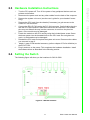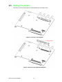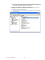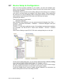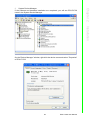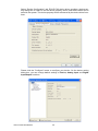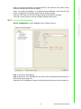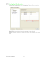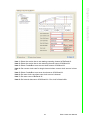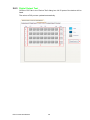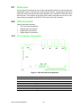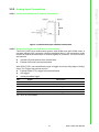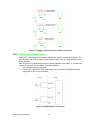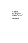
1
User Manual ECU-P1702 10 MS/s, 12bit, Simultaneous 4-ch Analog Input PCI-104 Bus Card Copyright The documentation and the software included with this product are copyrighted 2014 by Advantech Co., Ltd. All rights are reserved. Advantech Co., Ltd. reserves the right to make improvements in the products described in this manual at any time without notice. No part of this manual may be reproduced, copied, translated or transmitted in any form or by any means without the prior written permission of Advantech Co., Ltd. Information provided in this manual is intended to be accurate and reliable. However, Advantech Co., Ltd. assumes no responsibility for its use, nor for any infringements of the rights of third parties, which may result from its use. Acknowledgements Intel and Pentium are trademarks of Intel Corporation. Microsoft Windows and MS-DOS are registered trademarks of Microsoft Corp. All other product names or trademarks are properties of their respective owners. Product Warranty (2 years) Advantech warrants to you, the original purchaser, that each of its products will be free from defects in materials and workmanship for two years from the date of purchase. This warranty does not apply to any products which have been repaired or altered by persons other than repair personnel authorized by Advantech, or which have been subject to misuse, abuse, accident or improper installation. Advantech assumes no liability under the terms of this warranty as a consequence of such events. Because of Advantech’s high quality-control standards and rigorous testing, most of our customers never need to use our repair service. If an Advantech product is defective, it will be repaired or replaced at no charge during the warranty period. For outof-warranty repairs, you will be billed according to the cost of replacement materials, service time and freight. Please consult your dealer for more details. If you think you have a defective product, follow these steps: 1. Collect all the information about the problem encountered. (For example, CPU speed, Advantech products used, other hardware and software used, etc.) Note anything abnormal and list any onscreen messages you get when the problem occurs. 2. Call your dealer and describe the problem. Please have your manual, product, and any helpful information readily available. 3. If your product is diagnosed as defective, obtain an RMA (return merchandize authorization) number from your dealer. This allows us to process your return more quickly. 4. Carefully pack the defective product, a fully-completed Repair and Replacement Order Card and a photocopy proof of purchase date (such as your sales receipt) in a shippable container. A product returned without proof of the purchase date is not eligible for warranty service. 5. Write the RMA number visibly on the outside of the package and ship it prepaid to your dealer. ECU-P1706 User Manual Part No. XXXXXXXXXX Edition 1 Printed in China January 2014 ii Declaration of Conformity CE This product has passed the CE test for environmental specifications when shielded cables are used for external wiring. We recommend the use of shielded cables. This kind of cable is available from Advantech. Please contact your local supplier for ordering information. FCC Class A This equipment has been tested and found to comply with the limits for a Class A digital device, pursuant to part 15 of the FCC Rules. These limits are designed to provide reasonable protection against harmful interference when the equipment is operated in a commercial environment. This equipment generates, uses, and can radiate radio frequency energy and, if not installed and used in accordance with the instruction manual, may cause harmful interference to radio communications. Operation of this equipment in a residential area is likely to cause interference in which case the user is required to correct interference at his own expense. Technical Support and Assistance 1. 2. Visit the Advantech web site at www.advantech.com/support where you can find the latest information about the product. Contact your distributor, sales representative, or Advantech's customer service center for technical support if you need additional assistance. Please have the following information ready before you call: – Product name and serial number – Description of your peripheral attachments – Description of your software (operating system, version, application software, etc.) – A complete description of the problem – The exact wording of any error messages iii ECU-P1706 User Manual Safety Instructions 1. 2. 3. Read these safety instructions carefully. Keep this User Manual for later reference. Disconnect this equipment from any AC outlet before cleaning. Use a damp cloth. Do not use liquid or spray detergents for cleaning. 4. For plug-in equipment, the power outlet socket must be located near the equipment and must be easily accessible. 5. Keep this equipment away from humidity. 6. Put this equipment on a reliable surface during installation. Dropping it or letting it fall may cause damage. 7. The openings on the enclosure are for air convection. Protect the equipment from overheating. DO NOT COVER THE OPENINGS. 8. Make sure the voltage of the power source is correct before connecting the equipment to the power outlet. 9. Position the power cord so that people cannot step on it. Do not place anything over the power cord. 10. All cautions and warnings on the equipment should be noted. 11. If the equipment is not used for a long time, disconnect it from the power source to avoid damage by transient overvoltage. 12. Never pour any liquid into an opening. This may cause fire or electrical shock. 13. Never open the equipment. For safety reasons, the equipment should be opened only by qualified service personnel. 14. If one of the following situations arises, get the equipment checked by service personnel: The power cord or plug is damaged. Liquid has penetrated into the equipment. The equipment has been exposed to moisture. The equipment does not work well, or you cannot get it to work according to the user's manual. The equipment has been dropped and damaged. The equipment has obvious signs of breakage. 15. DO NOT LEAVE THIS EQUIPMENT IN AN ENVIRONMENT WHERE THE STORAGE TEMPERATURE MAY GO BELOW -20° C (-4° F) OR ABOVE 80° C (176° F). THIS COULD DAMAGE THE EQUIPMENT. THE EQUIPMENT SHOULD BE IN A CONTROLLED ENVIRONMENT. 16. CAUTION: DANGER OF EXPLOSION IF BATTERY IS INCORRECTLY REPLACED. REPLACE ONLY WITH THE SAME OR EQUIVALENT TYPE RECOMMENDED BY THE MANUFACTURER, DISCARD USED BATTERIES ACCORDING TO THE MANUFACTURER'S INSTRUCTIONS. The sound pressure level at the operator's position according to IEC 704-1:1982 is no more than 70 dB (A). DISCLAIMER: This set of instructions is given according to IEC 704-1. Advantech disclaims all responsibility for the accuracy of any statements contained herein. ECU-P1706 User Manual iv Chapter 1 Overview...............................................1 1.1 1.2 Introduction ............................................................................................... 2 Features .................................................................................................... 2 1.2.1 32-bits PCI-104 Bus Mastering DMA Data Transfer ..................... 2 1.2.2 A/D Converters for Simultaneous Sampling ................................. 2 1.2.3 Supports S/W, Internal & External Pacer Triggering..................... 3 1.2.4 On-board FIFO Memory................................................................ 3 1.2.5 Auto Calibration ............................................................................ 3 1.2.6 BoardID Switch ............................................................................. 3 Applications............................................................................................... 3 Installation Guide ...................................................................................... 3 Figure 1.1 Installation Flow Chart ................................................ 4 Software Overview .................................................................................... 4 1.5.1 Programming Choices for DA&C Cards........................................ 4 1.5.2 Device Drivers............................................................................... 4 Device Drivers Programming Roadmap.................................................... 4 1.6.1 Programming Tools....................................................................... 5 1.6.2 Programming with DAQNavi SDK................................................. 5 1.6.3 Troubleshooting Device Drivers Error........................................... 5 Specifications ............................................................................................ 6 Block Diagram........................................................................................... 6 Figure 1.2 ECU-P1702 Function Block........................................ 6 Dimensions Diagram................................................................................. 7 Figure 1.3 ECU-P1702 Dimensions Diagram .............................. 7 1.3 1.4 1.5 1.6 1.7 1.8 1.9 Chapter 2 Installation............................................9 2.1 2.2 2.3 2.4 Initial Inspection ...................................................................................... 10 Unpacking ............................................................................................... 10 Hardware Installation Instructions ........................................................... 11 Setting the Switch ................................................................................... 11 Figure 2.1 Switch location.......................................................... 11 2.4.1 Setting the BoardID switch (SW2) .............................................. 12 Table 2.1: Board ID Settings ..................................................... 12 2.4.2 Slot Select for PCI BUS (SW1) ................................................... 12 Table 2.2: Interrupt Settings ...................................................... 12 2.4.3 AI Input Impedance Select (SW3~SW6).................................... 13 Figure 2.2 Switch SW3 ~ SW6 Location.................................... 13 Table 2.3: AI Input Impedance Settings .................................... 13 Setting the Jumper .................................................................................. 14 Figure 2.3 ECU-P1702 Diagram................................................ 14 Figure 2.4 ECU-P1702 Exploded Diagram................................ 14 Figure 2.5 Jumper Location ....................................................... 15 Software Installation Instructions ............................................................ 15 2.6.1 DAQNavi SDK Installation .......................................................... 15 2.6.2 Devices Driver Installation .......................................................... 22 Device Setup & Configuration ................................................................. 28 2.7.1 Device Configuration................................................................... 31 2.7.2 Analog Input Configuration ......................................................... 32 2.7.3 Digital Input/ Output Configuration.............................................. 35 Device Test ............................................................................................. 36 2.8.1 Analog Input Test........................................................................ 36 2.8.2 Digital Input Test ......................................................................... 37 2.8.3 Digital Output Test ...................................................................... 38 2.5 2.6 2.7 2.8 Chapter 3 Signal Connections ...........................39 v ECU-P1706 User Manual 3.1 3.2 3.3 Overview ................................................................................................. 40 I/O Connector.......................................................................................... 40 3.2.1 I/O Connectors Description......................................................... 40 Figure 3.1 ECU-P1702 Pin Assignments .................................. 40 3.2.2 Analog Input Connections........................................................... 41 Figure 3.2 Differential Input Channel Connection...................... 41 Figure 3.3 Trigger Source and CLK Source Connection ........... 42 3.2.3 Digital Input Connections............................................................ 42 Figure 3.4 Digital Input Connections ......................................... 42 3.2.4 Digital Output Connections ......................................................... 43 Figure 3.5 Digital Output Connections....................................... 43 Field Wiring Considerations .................................................................... 43 4 Calibration ......................................... 45 4.1 4.2 Introduction ............................................................................................. 46 Calibration Procedure ............................................................................. 46 4.2.1 A/D Calibration Wizard ............................................................... 47 4.2.2 Retry Calibration ......................................................................... 49 4.2.3 Restore to Factory Default.......................................................... 49 Appendix A Specifications.................................... 51 A.1 A.2 A.3 A.4 General ................................................................................................... 52 Analog Input............................................................................................ 53 Digital Input ............................................................................................. 54 Digital Output .......................................................................................... 54 Appendix B Operation Theory .............................. 55 B.1 Analog Input Operation ........................................................................... 56 B.1.1 A/D Hardware Structure.............................................................. 56 B.1.2 Analog Input Ranges and Gains................................................. 56 Table B.1: Gains and Analog Input Range ................................ 56 B.1.3 Analog Input Acquisition Mode ................................................... 57 B.1.4 A/D Trigger Modes...................................................................... 59 B.1.5 A/D Trigger Source: .................................................................... 60 B.1.6 A/D Analog Trigger Hysteresis ................................................... 61 Chapter ECU-P1706 User Manual vi Chapter 1 1 Overview Sections include: Introduction Features Applications Installation Guide Software Overview Device Drivers Programming Roadmap Specifications Block Diagram Dimensions Diagram 1.1 Introduction The ECU-P1702 is a powerful high-speed multifunction card applied on PCI-104. It features a 10MHz 12-bit simultaneous A/D converter, an onboard FIFO buffer (storing up to 32 K samples for A/D). The ECU-P1702 provides a total of up to 4-ch signal end analog input. PCI-bus Plug and Play The dedicated PCI controller is embedded on ECU-P1702 to interface with PCI-104 Bus. It fully implements the PCI bus specification including all bus relative configurations, such as base address and interrupt assignment automatically controlled by software. While the ECU-P1702 shape is not standard PCI-104 card. Flexible Input Types and Range Settings The ECU-P1702 features an automatic channel/gain scanning circuit. Rather than software, which controls multiplexer switching during sampling, the on-board register stores different gain values and configurations for each channel. This design lets you perform multi-channel sampling with different gains for each channel. High-speed Data Acquisition The ECU-P1702 provides a sampling rate up to 10MS/s with 4 A/D converters simultaneously sampling on each channel and with a large FIFO of 32K samples. Moreover, BNC input type improves the stability of acquisition. 1.2 Features ECU-P1702 offers the following main features: 32-bit PCI bus Mastering DMA data transfer Four A/D converters for simultaneous sampling 12-bit A/D converter with up to 10Ms/s sampling rate On board 32K FIFO Memory 4 single-ended analog input channels Programmable gain for each input channel Multiple A/D triggering modes High ESD protection (±8 KV, ±15 KV) Auto calibration Board ID Switch Universal PCI interface, accepts both 3.3V and 5V Some of the features are described in details from the next page. 1.2.1 32-bits PCI-104 Bus Mastering DMA Data Transfer ECU-P1702 card supports PCI-104 bus mastering DMA for high-speed data transfers. By setting a block of memory in the ECU-1871, the card performs bus-mastering data transfers without CPU intervention. The CPU is freed to perform other more urgent tasks such as data analysis and graphic manipulation. The function allows users to run all I/O functions simultaneously at full speed without losing data. 1.2.2 A/D Converters for Simultaneous Sampling ECU-P1702 card is capable of simultaneous sampling with dedicated A/D converter circuit for each analog input channel. ECU-P1706 User Manual 2 ECU-P1702 card supports three kinds of trigger modes for A/D conversion: software triggering, internal pacer triggering and external pacer triggering. The software trigger can acquire a sample whenever needed, while the internal pacer saves CPU loading by triggering the sampling at a pre-programmed frequency. An external pacer can be used for triggering by external frequency source. Chapter 1 1.2.3 Supports S/W, Internal & External Pacer Triggering 1.2.4 On-board FIFO Memory 1.2.5 Auto Calibration ECU-P1702 card features software auto calibration application. It provides convenient method for user calibration processing. 1.2.6 BoardID Switch ECU-P1702 cards have been installed on the same PC chassis. The BoardID setting function is very useful when building a system with multiple ECU-P1702 cards. With the correct BoardID settings, you can easily identify and access each card during hardware configuration and software programming. Note! For detailed specifications of the ECU-P1702 cards, please refer to Appendix A, Specifications. 1.3 Applications The following are some of the possible applications of ECU-P1702 cards: Testing Instruments Partial Discharging Detection and Analytical Devices Designed for Smart-Grid Applications 1.4 Installation Guide Before you install your ECU-P1702 card, please make sure you have the following necessary components: ECU-P1702 DA&C card ECU-P1702 User Manual Driver software Advantech DAQNavi SDK and drivers (included in the companion CD-ROM) External Connector PLUG-IN BLOCK 5P 1PCS connector Computer Personal computer or workstation with a PCI-104 bus slot (running XP, Vista or Windows 7). Some optional components are also available for enhanced operation: After you get the necessary components and maybe some of the accessories for enhanced operation of your Multifunction card, you can then begin the installation procedures. Figure 1.1 on the next page provides a concise flow chart for a broad picture of the software and hardware installation procedure: 3 ECU-P1706 User Manual Overview There is 32k of FIFO sample memory on ECU-P1702. This is an important feature for faster data-transfer and more predictable performance under Windows systems. Figure 1.1 Installation Flow Chart 1.5 Software Overview Advantech offers a rich set of APIs, third-party driver supports and application software to help fully utilize the functions of your ECU-P1702 cards: Device Drivers (on the companion CD-ROM) DAQNavi SDK 1.5.1 Programming Choices for DA&C Cards You may use Advantech application software such as Advantech Device Drivers. On the other hand, advanced users may choose register-level programming, although it is not recommended due to its laborious and time-consuming nature. 1.5.2 Device Drivers The Advantech Device Drivers software is included on the companion CD-ROM. It also comes with all Advantech DA&C cards. Advantech’s device drivers feature a complete I/O function library to help boost your application performance. The Advantech Device Drivers for Windows XP or Windows 7 works seamlessly with development tools such as Visual C++, Visual C#, Visual Basic.NET, Borland C++ Builder and Borland Delphi. 1.6 Device Drivers Programming Roadmap This section will provide you a roadmap to demonstrate how to build an application from scratch using Advantech Device Drivers with your favorite development tools such as Visual C++, C#, Visual Basic.NET, Delphi and C++ Builder. The step-by-step instructions on how to build your own applications using each development tool will be given in the Device Drivers Manual. Moreover, a rich set of example source code is also given for your reference. ECU-P1706 User Manual 4 1.6.2 Programming with DAQNavi SDK Advantech DAQNavi SDK offers a rich function library to be utilized in various application programs. This function library consists of numerous APIs that support many development tools, such as Visual C++, C#, Visual Basic.NET, Delphi and C++ Builder. According to their specific functions or services, the APIs can be categorized into several function groups: Device Function Analog Input Function Digital Input/ Output Function For the usage and parameters of each function, please refer to the Function Description chapter in the Device Drivers Manual. 1.6.3 Troubleshooting Device Drivers Error Driver functions will return a status code when they are called to perform a certain task for the application. When a function returns a code that is not zero, it means the function has failed to perform its designated function. See Device Driver Manual for detailed information about Error Code. 5 ECU-P1706 User Manual Overview Programmers can develop application programs with their favorite development tools: Visual C++ Visual C# Visual Basic.NET Delphi C++ Builder LabVIEW For instructions on how to begin programming in each development tool, Advantech offers a Tutorial Chapter in the Device Drivers Manual for your reference. Please refer to the corresponding sections in this chapter of the Device Drivers Manual to begin your programming efforts. You can also look at the example source code provided for each programming tool. The Device Drivers Manual can be found on the companion CD-ROM. Or if you have already installed the Device Drivers on your system, the Device Drivers Manual can be readily accessed through the Start button: Start/Programs/Advantech Automation/DAQNavi/DAQNavi Manuals The example source codes can be found under the corresponding installation folder such as the default installation path: C:\Advantech\DAQNavi\Examples\ For information about using other function groups or other development tools, please refer to the Device Driver Programming Guide and the Function Reference on the Device Drivers Manual. Chapter 1 1.6.1 Programming Tools 1.7 Specifications General Power Consumption: 5 V @ 700 mA (max.), 3.3 V @ 850 mA (max.) Bus Type: PCI-104 I/O Connector: BNC, Plug-in Terminal Block Operating Temperature: -20 ~ 70°C (-4 ~158° F) @ 5 ~ 85% RH Storage Temperature: -40 ~ 80°C (-40 ~176° F) Storage Humidity: 5 ~ 95% RH, non-condensing (IEC 60068-2-3) Analog Input Channels: 4 single-ended Resolution: 12 bits Max. Sampling Rate: 10MS/s FIFO Size: 32 K/ Channel Overvoltage Protection: ±14V Input Impedance: 50 ohm/1M ohm/Hi Z switch selectable Sampling Mode: Software, onboard programmable pacer and external (TTL Level) Trigger Mode: Delay To Start Trigger, Delay To Stop Trigger Trigger Source: Analog Trigger, External Trigger Input Range: ±5 V, ±2.5 V, ±1 V, ±0.5 V Digital Input/ Output Channels: 32 (Setting DIO in the same direction) Input Range: 5 V/TTL, Logic 0: 0.8 V max. Logic 1: 2 V min. Output Range: 5 V/TTL, Logic 0: 0.4 V max. Logic 1: 2.4 V min. 1.8 Block Diagram Figure 1.2 ECU-P1702 Function Block ECU-P1706 User Manual 6 Chapter 1 1.9 Dimensions Diagram Overview Figure 1.3 ECU-P1702 Dimensions Diagram 7 ECU-P1706 User Manual ECU-P1706 User Manual 8 Chapter 2 2 Installation Sections include: Initial Inspection Unpacking Hardware Installation Instructions Setting the Switch Setting the Jumper Software Installation Instructions Device Setup & Configuration Device Test 2.1 Initial Inspection Before installing the ECU-P1702, check the card for visible damage. We have carefully inspected the card both mechanically and electrically before shipment. It should be free of marks and in perfect order upon receipt. As you unpack the ECU-P1702, check it for signs of shipping damage (damaged box, scratches, dents, etc.). If it is damaged or fails to meet specifications, notify our service department or your local sales representative immediately. Also, call the carrier immediately and retain the shipping carton and packing materials for inspection by the carrier. We will then make arrangements to repair or replace the unit. 2.2 Unpacking After receiving your ECU-P1702 package, please inspect its contents first. The package should contain the following items: (A) ECU-P1702 card (B) PLUG-IN BLOCK 5P 1PCS (C) F=M3 x 10L H=15.3 mm Cu 6 PCS (D) 1 x front panel (for ECU-P1702) (E) Energy Series Driver and Utility DISC (F) 1x ROHS LIST (G) 1 x warranty card The ECU-P1702 cards harbors certain electronic components vulnerable to electrostatic discharge (ESD). ESD could easily damage the integrated circuits and certain components if preventive measures are not carefully paid attention to. Before removing the card from the antistatic plastic bag, you should take following precautions to ward off possible ESD damage: Touch the metal part of your computer chassis with your hand to discharge static electricity accumulated on your body. Or use a grounding strap. Touch the anti-static bag to a metal part of your computer chassis before opening the bag. Hold the card only by the metal bracket when removing it from the bag. After taking out the card, you should first inspect the card for any possible signs of external damage (loose or damaged components, etc.). If the card is visibly damaged, please notify our service department or the local sales representative immediately. Avoid installing a damaged card into your system. Also, pay extra caution to the following aspects to ensure proper installation: Avoid physical contact with materials that could hold static electricity such as plastic, vinyl and Styrofoam. Whenever you handle the card, grasp it only by its edges. DO NOT TOUCH the exposed metal pins of the connector or the electronic components. Note! Keep the anti-static bag for future use. You may need the original bag to store the card if you have to remove the card from the PC or transport it elsewhere. ECU-P1706 User Manual 10 1. 2. 3. 4. 6. 7. 8. 9. 2.4 Setting the Switch The following figure will show you the locations for SW1 & SW2. Figure 2.1 Switch location 11 ECU-P1706 User Manual Installation 5. Turn the PC’s power off. Turn off the power of any peripheral devices such as printers and monitors. Disconnect the power cord and any other cables from the back of the computer. Remove the system unit cover (see the user’s guide for your chassis if necessary). Remove the CPU card from the chassis (if necessary) to gain access to the card’s PCI-104 connector. Connect the ECU-P1702 card to the PCI-104 connector. Carefully align the pins with the PCI-104 connector. Slide the module into the connector. The module pins may not slide all the way into the connector; do not force the pins into place, or the module may be damaged. Fasten the module to the CPU card by using the included brass screw. Screw the brass spacer into the threaded hole on the CPU card. Do not tighten too much, or the threads may be damaged. Reinstall the CPU card and replace the system unit cover. Reconnect the cables you removed in step 2. Attach 1 green 5 PIN terminal accessory (refer to chapter 3 Pin for definition) to the ECU-P1702. Plug in and turn on the power. This completes the hardware installation. Install the software driver as described in the following section. Chapter 2 2.3 Hardware Installation Instructions 2.4.1 Setting the BoardID switch (SW2) The ECU-P1702 has a built-in DIP switch (SW1), which is used to define each card's board ID. You can determine the board ID on the register as shown in Table 2.1. When there are multiple cards on the same chassis, this board ID setting function is useful for identifying each card's device number through board ID. We set the ECUP1702 board ID as 0 at the factory. If you need to adjust it to other board ID, set the SW1 by referring to DIP switch setting. Table 2.1: Board ID Settings SW2 3 2 1 0 BoardID ID3 ID2 ID1 ID0 0* ON ON ON ON 1 ON ON ON OFF 2 ON ON OFF ON 3 ON ON OFF OFF 4 ON OFF ON ON 5 ON OFF ON OFF 6 ON OFF OFF ON 7 ON OFF OFF OFF 8 OFF ON ON ON 9 OFF ON ON OFF 10 OFF ON OFF ON 11 OFF ON OFF OFF 12 OFF OFF ON ON 13 OFF OFF ON OFF 14 OFF OFF OFF ON 15 OFF OFF OFF OFF 2.4.2 Slot Select for PCI BUS (SW1) The ECU-P1702 has a built-in DIP switch (SW1), which is used to define each card's interrupt number. You can determine the INT ID as shown in Table 2.2. When there are multiple cards on the same chassis, this INT ID setting function is useful for each card. We set the ECU-P1702 INT ID as 0 at the factory. If you need to adjust it to other INT ID, set the SW1 by referring to DIP switch setting. Table 2.2: Interrupt Settings Position1 Position2 Switch Value Module Slot REQ# GNT# CLK INT0# ON GNT0# CLK0 INTA# ON 0 0 REQ0# ON OFF 1 1 REQ1# GNT1# CLK1 INTB# OFF ON 2 2 REQ2# GNT2# CLK2 INTC# OFF OFF 3 3 REQ3# GNT3# CLK2 INTD# Tip: If Position1 and Position2 on SW1 both setting as OFF, the ECU-P1702 card could not be detected. ECU-P1706 User Manual 12 AI Input Impedance Select (SW3~SW6) The following figure 2.2 will show you the locations for SW3 ~ SW6. Chapter 2 2.4.3 Installation Figure 2.2 Switch SW3 ~ SW6 Location The ECU-P1702 has four built-in DIP switch (SW3~SW6), which are used to select different input impedance for each AI channel. You can determine the impedance value as shown in Table 2-3. Wet set the ECU-P1702 impedance as Hi Z at the factory. If you need to adjust it to other impedance, set the SW3~SW6 by referring to DIP switch setting. Table 2.3: AI Input Impedance Settings Switch Value Impedance Value 00 Hi Z 01 1M Ohm 10 50 Ohm 11 ERROR 13 ECU-P1706 User Manual 2.5 Setting the Jumper The ECU-P1702 is composed of a motherboard and a jumper board. Figure 2.3 ECU-P1702 Diagram Figure 2.4 ECU-P1702 Exploded Diagram ECU-P1706 User Manual 14 Chapter 2 The following figure will show you the location of jumper connector for CN16. Installation Figure 2.5 Jumper Location 2.6 Software Installation Instructions 2.6.1 DAQNavi SDK Installation For developer, we recommend you to install driver from Advantech Navigator. Advantech Navigator will be installed with DAQNavi SDK Package, so the developer need not download the individual driver package. The user to build operation environment need not download and install DAQNavi SDK Package, user can only download and install the individual driver Package "DAQNavi_ECUP1702". Install driver for development Install driver for building operation environment Install driver for development: We offer two ways for driver installation: Installation Preinstallation Uninstallation We recommend you use the device auto Installation and insert the card into your system before installing the driver to ensure that the installation process will be completed smoothly. 15 ECU-P1706 User Manual Installation (Recommended) You can install the ECU-P1702 card in any PCI-104 slot on your computer. Please follow the following steps below to install the module on your system. 1. Turn off your computer and unplug the power cord and cables. TURN OFF your computer before installing or removing any components on the computer. 2. Remove the cover of the computer. 3. Remove the slot cover on the back panel of your computer. 4. Touch the metal part on the surface of your computer to neutralize the static electricity that might be on your body. 5. Adjust DIP switch SW2 on board to set the card's board ID. 6. Insert the ECU-P1702 card into a PCI-104 slot. Hold the card only by its edges and carefully align it with the slot. Insert the card firmly into place. Use of excessive force must be avoided, otherwise the card might be damaged. 7. Fasten the bracket of the PCI-104 card on the back panel rail of the computer with screws. 8. Connect appropriate accessories(68-pin cable, wiring terminals, etc. if necessary) to the PCI-104 card. 9. Replace the cover of your computer chassis. Re-connect the cables you removed in step 2. 10. Plug in the power cord and turn on the computer. 11. Install DAQNavi SDK from DVD for building your operation environment. 1). Insert the companion DVD into your DVD disc. The setup program will be launched automatically if you have the autorun function enabled on your system. Then the setup program will be launched. 2). Push the “CONTINUE” button to next step. ECU-P1706 User Manual 16 Chapter 2 3). Select the “Installation” option. Installation 4). Select the “ECU Series” option. 17 ECU-P1706 User Manual 5). Select the “ECU-P1702” option. 6). If the client need to develop other applications they need on ECU-P1702, please Select the " SDK " option to install ECU-P1702 DAQNavi SDK Package. so the developer need not download the individual driver package. ECU-P1706 User Manual 18 ECU-P1706 User Manual Installation 19 Chapter 2 7). After DAQNavi SDK have been installed successfully , Advantech Navigator will be lunched automatically. Of course, you can open the Advantech Navigator from "Start >> All Programs >> Advantech Automation >> DAQNavi >> Adventech Navigator" manually. For win7 user, you must run it by right click the item and select the 'Run As Administrator' item from the popup menu. 8). Click "+" on the left of node named "Supported Devices" to expand the contents, then all the supported devices will be listed under this node. 9). Choose the device which you want to install driver, right click on the node, there will be a popup dialog shown, click "Install Driver" on the dialog, thus, the driver will start to install. 10). Click "OK" to finish installation. Navigator detects and installs ECU-P1702 device on the system automatically, then you can find "ECU-P1702" device node under "Installed Devices" node. Preinstallation ECU-P1702 DAQNavi Driver supply device preinstallation if you have installed ECUP1702 DAQNavi Driver from Navigator but without inserting the ECU-P1702 card in your system. 1. Install ECU-P1702 DAQNavi Driver from Navigator. 2. Turn off your computer and unplug the power cord and cables. TURN OFF your computer before installing or removing any components on the computer. 3. Remove the cover of the computer. 4. Remove the slot cover on the back panel of your computer. 5. Touch the metal part on the surface of your computer to neutralize the static electricity that might be on your body. 6. Adjust DIP switch SW2 on board to set the card's board ID. 7. Insert the ECU-P1702 card into a PCI-104 slot. Hold the card only by its edges and carefully align it with the slot. Insert the card firmly into place. Use of excessive force must be avoided, otherwise the card might be damaged. 8. Fasten the bracket of the PCI-104 card on the back panel rail of the computer with screws. 9. Connect appropriate accessories to the PCI-104 card. 10. Replace the cover of your computer chassis. Re-connect the cables you removed in step 2. 11. Plug in the power cord and turn on the computer. 12. In a Windows XP system: Access the "System Device Manager". System will recognize PCI device and pop up an dialog, click "next" button to complete the installation process. Or else you can install the device driver by right click on the PCI device item and select "Update" button to install ECU-P1702 driver. ECU-P1706 User Manual 20 In a Windows 7 system: Access the "System Device Manager". System will recognize ECU-P1702 device and the driver of ECU-P1702 will be installed automatically without any notice information. Note! Uninstallation 1. Close the applications of the ECU-P1702. 2. Run Advantech Navigator. For win7 user, you must run it by right click the item and select the 'Run As Administrator' item from the popup menu. 3. Click "+" on the left of node named "Installed Devices" to expand the contents, then all the installed devices will be listed under this node. 4. Choose the device which you want to uninstall driver, right click on the node, there will be a popup dialog shown, click "uninstall Driver" on the dialog, thus, the driver will start to uninstall. 21 ECU-P1706 User Manual Installation If your card has been installed properly, you can see the device name of your card listed on the "System Device Manager" under "Advantech DAQ device" node. If you do see the device name listed under it but marked with an exclamation sign "!" , it means your device's driver has not been installed correctly and successfully . In this case, you can select the device name and press the "Update" button to update driver manually. Chapter 2 2.6.2 Devices Driver Installation Install driver for building operation environment: We offer two ways for driver installation: Installation Preinstallation Uninstallation We recommend use the driver auto Installation way and that you to install the card into your system before installing the driver, thus to ensure that the device driver will be installed smoothly. Installation (Recommended) You can install the ECU-P1702 card in any PCI-104 slot on your computer. Please follow the steps below to install the module on your system. 1. Turn off your computer and unplug the power cord and cables. TURN OFF your computer before installing or removing any components on the computer. 2. Remove the cover of the computer. 3. Remove the slot cover on the back panel of your computer. 4. Touch the metal part on the surface of your computer to neutralize the static electricity that might be on your body. 5. Adjust DIP switch SW2 on board to set the card's board ID. 6. Insert the ECU-P1702 card into a PCI-104 slot. Hold the card only by its edges and carefully align it with the slot. Insert the card firmly into place. Use of excessive force must be avoided, otherwise the card might be damaged. 7. Fasten the bracket of the PCI-104 card on the back panel rail of the computer with screws. 8. Connect appropriate accessories (68-pin cable, wiring terminals, etc. if necessary) to the PCI-104 card. 9. Replace the cover of your computer chassis. Re-connect the cables you removed in step 2. 10. Plug in the power cord and turn on the computer. 11. Install ECU-P1702 DAQNavi driver from DVD for building your operation environment. 1). Insert the companion DVD into your DVD disc. The Setup program will be launched automatically if the auto play function enabled on your system. When the Setup Program is launched, you will see the following setup screen. ECU-P1706 User Manual 22 Chapter 2 2). Push the “CONTINUE” button to next step. Installation 3). Select the "Installation" option. 23 ECU-P1706 User Manual 4). Select the "ECU Series" option. 5). Select the "ECU-P1702" option. ECU-P1706 User Manual 24 Chapter 2 6). If the client need only apply the ECU-P1702, please Select the " DAQ " option to install ECU-P1702 DAQNavi Driver Package. Installation 7). Run the ECU-P1702 DAQNavi Driver package. 25 ECU-P1706 User Manual 8). Click "Finish". The installer detects and installs ECU-P1702 device on the system automatically. The device driver files and manual can be found at: System disk\Advantech\DAQNavi\Driver\ECU-P1702. 12. After the ECU-P1702 driver is installed, you can verify whether it is properly installed on your system in the System Device Manager: 1). Access the System Device Manager. 2). The device name of the ECU-P1702 should be listed under the Advantech DAQ Devices tab. ECU-P1706 User Manual 26 If your card has been installed properly, you can see the device name of your card listed on the "System Device Manager" under "Advantech DAQ device" node. If you do see the device name listed under it but marked with an "!"sign, it means your device's driver has not been installed correctly and successfully . In this case, you can select the device name and press the "Update" button to update driver manually. Uninstallation 1. Close the applications of the PCI module. 2. Run the ECU-P1702 DAQNavi Driver package, select the "Remove", then the ECU-P1702 driver will be uninstalled. 27 ECU-P1706 User Manual Installation Note! Chapter 2 Preinstallation ECU-P1702 DAQNavi Driver supply device preinstallation if you have installed ECUP1702 DAQNavi Driver from DVD but without inserting the ECU-P1702 card in your system. 1. Install ECU-P1702 DAQNavi Driver from DVD 2. Turn off your computer and unplug the power cord and cables. TURN OFF your computer before installing or removing any components on the computer. 3. Remove the cover of the computer. 4. Remove the slot cover on the back panel of your computer. 5. Touch the metal part on the surface of your computer to neutralize the static electricity that might be on your body. 6. Adjust DIP switch SW1 on board to set the card's board ID. 7. Insert the ECU-P1702 card into a PCI-104 slot. Hold the card only by its edges and carefully align it with the slot. Insert the card firmly into place. Use of excessive force must be avoided, otherwise the card might be damaged. 8. Fasten the bracket of the PCI-104 card on the back panel rail of the computer with screws. 9. Connect appropriate accessories to the PCI-104 card. 10. Replace the cover of your computer chassis. Re-connect the cables you removed in step 2. 11. Plug in the power cord and turn on the computer. 12. In Windows XP system: Access the "System Device Manager". System will recognize PCI device and pop up an dialog, click "next" button to complete the installation process. Or else you can install the device driver by right click on the PCI device item and select "Update" button to install ECU-P1702 driver. In Windows 7 system: Access the "System Device Manager". System will recognize ECU-P1702 device and the driver of ECU-P1702 will be installed automatically without any notice information. 2.7 Device Setup & Configuration After your card is properly installed on your system, you can now configure your device using the Device Configuration Program that has itself already been installed during driver installation. The DAQNavi Driver provides device setting dialog box that allows you to configure your device, and later stores your settings on the system registry. These settings will be used when you call the DAQNavi SDK to manipulate functions of Device Configuration assists to use Advantech DAQ cards more efficiently and easily. Configuring the Device: There are two ways to setup device: 1. Advantech Navigator After DAQNavi SDK installation, you can access Advantech Navigator from "Start → Programs →Advantech Automation →DAQNavi → Advantech Navigator" and open Navigator window. Click the "+" on the left to unfold the content. If the software and hardware installation are completed, the ECU-P1702 is listed under DAQNavi →Devices →Installed Devices. Select Device Setting to open ECU-P1702 device setting dialog box on the right. On the device setting dialog box, you can change default settings of Device, Analog Input, Analog Output, Digital Input/Output and Counter functions. With the corresponding check box checked, you can click the "Save" button to apply the device setting to the device or store them in the system registry. If both the "Update Device" and the "Update System Database" are unchecked, the device setting will be lost once the dialog is closed. ECU-P1706 User Manual 28 Chapter 2 2. System Device Manager If the software and hardware installation are completed, you will see ECU-P1702 name in the System Device Manager. Installation On the "Device Manager" window, right click the device name and select "Properties" of ECU-P1702. 29 ECU-P1706 User Manual Select “Device Configuration” tab. ECU-P1702 device driver provides a device setting dialog box for users to set the device property values, and these values will be saved in the system. The device property will be referenced by the device driver functions. Please click the "Configure" button to configure your device. On the device setting dialog box, you can change default settings of Device, Analog Input and Digital Input/Output functions. ECU-P1706 User Manual 30 Chapter 2 When you check the checkbox of "Update Device", after click the "OK" button, configuration information will be set into device. When you check the checkbox of "Update System Database", after click the "OK" button, configuration information will be set into system registry. Click the "OK" button to exit the configure dialog and accept the changes. Click the "Cancel" button to exit the configure dialog without save. 2.7.1 Device Configuration Item 1: Set device descriptions. Item 2: Select the "Yes" RadioButton, the device will be initialized with the initial condition when device power on. Select the "No" RadioButton, the device will keep last status when device power on. 31 ECU-P1706 User Manual Installation Device Configuration: Select "Device" tab to configure device. 2.7.2 Analog Input Configuration Analog Input Configuration: Select "Analog Input" tab to configure analog input. Item 1: Select the combo box to set value range type for each channel. Item 2: Check the checkbox to configure all channels with the same value range type. ECU-P1706 User Manual 32 Chapter 2 Installation Item 1: Select the combo box to set starting scanning channel of Buffered AI. Item 2: Select the combo box to set scanning channel count of Buffered AI. Item 3: Select ComboBox to set convert clock source of Buffered AI. Item 4: Set convert clock rate for single channel when convert clock source is internal. Item 5: Select ComboBox to set scan clock source of Buffered AI. Item 6: Set scan clock rate when scan clock source is internal. Item 7: Set scan count of Buffered AI. Item 8: Set interval data count of Buffered AI. 0 for a half of data buffer. 33 ECU-P1706 User Manual Item 1: Set the signal source of trigger used by buffered AI sampling. Item 2: Set the threshold value of the trigger signal. This is only for the signal which is analog type signal. Item 3: Set the signal edge of trigger source at which the signal is considered as a valid trigger signal. Item 4: Set the action to be executed after the trigger condition is satisfied. Item 5: Show how many scan clocks or conversion clocks( if the scan clock is not supported ) to delay before executing the action specified by TriggerAction. ECU-P1706 User Manual 34 Digital Input/ Output Configuration: Select "Digital Input/Output" tab to configure digital IO. Chapter 2 2.7.3 Digital Input/ Output Configuration Installation Item 1: Set DIO direction. Item 2: Set initial value for DO ports. 35 ECU-P1706 User Manual 2.8 Device Test After device setup, you can select Device Test to open ECU-P1702 device test dialog box in Navigator window. In the "Device Test" dialog box, users can select different tabs to test various functions of ECU-P1702. Analog Input Test Digital Input Test Digital Output Test 2.8.1 Analog Input Test Click the "AI" tab in the "Device Test" dialog box. All the AI physical channels of the device will be listed on the left. Values of AI channels are updated periodically. Users are able to edit the value range of AI channels at any time by clicking the value range type in the list. Item 1: Shows the number of a corresponding analog input channel. Check the checkbox and the corresponding analog input channel will be selected. The list box list value range type for each channel. The user can select the value range type in the list box. Item 2: Shows the sample data in graphics of each channel. Item 3: Shows Analog input function supported by device. ECU-P1702 series supports instant AI and buffered AI. Item 4: Shows frequency of analog input sampling. Configure the sampling rate on the scroll bar or edit the textbox. The textbox is used to show current frequency. Item 5: "Start/Stop" button is used to start or stop analog input. ECU-P1706 User Manual 36 Click the "DI" tab in the "Device Test" dialog box. All DI ports of the device will be listed. The values of DI port are updated automatically. Chapter 2 2.8.2 Digital Input Test Installation 37 ECU-P1706 User Manual 2.8.3 Digital Output Test Click the "DO" tab in the "Device Test" dialog box. All DI ports of the device will be listed. The values of DO port are updated automatically. ECU-P1706 User Manual 38 Chapter 3 3 Signal Connections Sections include: Overview I/O Connector Field Wiring Considerations 3.1 Overview Correct signal connections are one of the most important factors in ensuring that your application system is sending and receiving data correctly. A good signal connection can avoid much unnecessary and costly damage to your valuable PC and other hardware devices. This chapter will provide some useful information about how to connect analog input signals to the ECU-P1702 card via the I/O connector. 3.2 I/O Connector Signal Connections include: 1. I/O Connectors Description 2. Analog Input Connections 3. Digital Input Connections 4. Digital Output Connections 3.2.1 I/O Connectors Description Figure 3.1 ECU-P1702 Pin Assignments Connector Function CN1 Analog input CH-0 CN4 Analog input CH-1 CN6 Analog input CH-2 CN8 Analog input CH-3 CN11 Digital input/output CN15 Ext. Trigger & CLK ECU-P1706 User Manual 40 Chapter 3 3.2.2 Analog Input Connections 3.2.2.1 Instant AI and Buffered AI Channel Connections 3.2.2.2 Buffered AI Trigger and CLK Source Connections The ECU-P1702 has a double-clock system, with SCAN clock and CONV clock, to generate efficient A/D conversion clocks at dedicated timing. A/D conversion clocks come from internal clock sources or external signals on connector. The CLK has several sources. Internal A/D clock derived from 32-bit divider External A/D clock from terminal board With ECU-P1702, user can define the type of trigger source as rising-edge or fallingedge. The Trigger has several sources. External digital (TTL) trigger from terminal board Soft trigger Analog threshold trigger PIN Signal Description 1 GND GND 2 CLK1 Ext. Scan CLK 3 TRG1 Ext. Trigger 1 4 CLK0 Ext. Convert CLK 5 TRG0 Ext. Trigger 0 Tip: TRG1 is not available. 41 ECU-P1706 User Manual Signal Connections Figure 3.2 Differential Input Channel Connection Figure 3.3 Trigger Source and CLK Source Connection 3.2.3 Digital Input Connections The ECU-P1702 supports 32-channel digital input which is divided to 4 groups. The type includes wet contact input and dry contact input. User can only set DIO at the same direction. Now DI function is reserved because no wiring extraction from panel. If you want to use the DI function, two conditions should be satisfied: 1. You can lead wire from the card; 2. Ensure only one ECU-P1702 card (without any other ECU-P1000 series card) supported on ECU-1871 controller. Figure 3.4 Digital Input Connections ECU-P1706 User Manual 42 The ECU-P1702 supports 32-channel digital output which is divided to 4 groups. The type is TTL output. User can only set DIO at the same direction. Now DO function is reserved because no wiring extraction from panel. If you want to use the DO function, two conditions should be satisfied: 1. You can lead wire from the card; 2. Ensure only one ECU-P1702 card (without any other ECU-P1000 series card) supported on ECU-1871 controller. Chapter 3 3.2.4 Digital Output Connections Signal Connections Figure 3.5 Digital Output Connections 3.3 Field Wiring Considerations When you use ECU-P1702 cards to acquire data from outside, noises inthe environment might significantly affect the accuracy of your measurements if due cautions are not taken. The following measures will be helpfulto reduce possible interference running signal wires between signal sources and the ECU-P1702 card. The signal cables must be kept away from strong electromagneticsources such as power lines, large electric motors, circuit breakers orwelding machines, since they may cause strong electromagnetic interference.Keep the analog signal cables away from any video monitor,since it can significantly affect a data acquisition system. If the cable travels through an area with significant electromagneticinterference, you should adopt individually shielded, twisted-pair wiresas the analog input cable. This type of cable has its signal wires twistedtogether and shielded with a metal mesh. The metal mesh should onlybe connected to one point at the signal source ground. Avoid running the signal cables through any conduit that might havepower lines in it. If you have to place your signal cable parallel to a power line that has ahigh voltage or high current running through it, try to keep a safe distancebetween them. Alternatively, you can place the signal cable at aright angle to the power line to minimize the undesirable effect. 43 ECU-P1706 User Manual ECU-P1706 User Manual 44 Chapter 4 Calibration Sections include: Introduction Calibration Procedure 4 4.1 Introduction The ECU-P1702 has been calibrated at the factory for initial use. You are not required to calibrate the ECU-P1702 in normal conditions. However, if in other conditions users need to calibrate the ECU-P1702, users can follow the process list below. To perform a satisfactory calibration, users need a 6-1/2 digit voltmeter and a low noise standard DC voltage source for the calibration process. It is important that the accuracy after calibration depends on the precision voltmeter's accuracy. 4.2 Calibration Procedure Auto A/D Calibration Note! User should calibrate A/D function first before calibrating D/A function. Please Click the "Calibration" tab in configuration dialog box and follow the Calibration Instructions to finish your calibration. Item1: Display Analog Input Calibration (A/D Calibration). ECU-P1706 User Manual 46 Chapter 4 4.2.1 A/D Calibration Wizard Introduction: Calibration Item 1: Before start calibration, read the instructions: 1. Stop any running operations of the device; 2. Connect your voltmeter to TP1 and TP2, adjust VR1 until the voltage is 2.5V. (See this page for the position of TP1/TP2/VR1.) 3. Select channels in the following list. Hold CTRL key and left chick the list item while selecting multiple channels. All channels are selected for default. Item 2: Display the calibration status and result during the process. 1. Calibrate offset 47 ECU-P1706 User Manual Item 1: Connect a 0V DC to the channel(s) selected above and click Start button. Item 2: Display some values during calibration process. These values are for internal use, send them to Advantech if calibration fails. Item 3: Display the calibration result. If success the status is Done otherwise is "Failed". 2. Calibrate gain Item 1: Select a gain in the combo box and connect a specific signal to the AI channel(s). Note! The signal voltage is different at different gain, see the red box marked "1" for the correct value. Item 2: Click "Start" button to start calibrating. Item 3: Display some values during calibration process. These values are for internal use, send them to Advantech if calibration fails. Item 4: Display the calibration result. If success the status is Done otherwise is "Failed". Item 5: Select another gain to calibrate and repeat the 1-4 above. ECU-P1706 User Manual 48 Chapter 4 4.2.2 Retry Calibration Calibration Item 1: Display some channels which fails in calibration process. Item 2: Select the failed channels and re-click "Start" button to try again. 4.2.3 Restore to Factory Default Item 1: Click "Stop" button to stop calibration process. Item 2: Click "Default" button to restore factory settings. 49 ECU-P1706 User Manual ECU-P1706 User Manual 50 Appendix A Specifications Sections include: General Analog Input Digital Input Digital Output A A.1 General I/O Connector Type 4 BNC connector for AI 1 Plug-in terminal block connector for ext. clock and trigger Dimensions 133.08 x 184 mm (5.2" x 7.2") Power Consumption +5 V @ 700 mA (max.) +3.3 V @ 850 mA (max.) Temperature Operation -20 ~ 70°C (-4 ~ 158°F) (refer to IEC60068-2-1,2) Storage -40 ~ 80°C (-40 ~176°F) Operation 5 ~ 85% RH non-condensing (refer to IEC60068-1-2,-3) Storage 5 ~ 95% RH non-condensing (refer to IEC60068-1-2,-3) Relative Humidity Certification ECU-P1706 User Manual CE/FCC Certified 52 Channels 4 single-ended analog input channels Resolution 12-bit Simultaneous Max. Sampling Rate 10MHZ Input range and Gain List Gain FIFO Size 32K 1 2 5 10 Range ±5 V ±2.5 V ±1 V ±0.5 V Gain 1 2 5 10 Zero (μV/° C) ±30 ±30 ±30 ±30 Gain (ppm/° C) ±30 ±30 ±30 ±30 Small Signal Bandwidth for PGA Gain 1 2 5 10 Bandwidth (-3 dB) 10 MHz 8 MHz 5 MHz 3 MHz Max. Input voltage ±14 V OverVoltage Protection Input Impedance 50 ohm/1M ohm/Hi Z switch selectable Trigger Mode Delay To Start Trigger, Delay To Stop Trigger Trigger source Analog Trigger, External Trigger Drift Accuracy External Clock External Trigger External Analog Trigger Input DC ±15 V INLE ±3 LSB DNLE ±2 LSB Monotonicity 12 bits Offset Error Adjustable to zero Gain 1 2 5 10 Gain Error(%FSR) 0.1 0.1 0.2 0.2 Logic level TTL (Low: 0.8 V max. High: 2.0V min.) Input impedance Hi Z Input coupled DC Frequency Up to 10 MHz Logic level TTL (Low: 0.8 V max. High: 2.0V min.) Input impedance Hi Z Input coupled DC Range By analog input range Resolution 8-bit Frequency Up to 1 MHz 53 ECU-P1706 User Manual Appendix A Specifications A.2 Analog Input A.3 Digital Input Channels 32 channels (set DIO in same direction) Compatibility 5 V/ TTL Input Voltage Logic 0 0.8 V max. Logic 1 2 V min. A.4 Digital Output Channels 32 channels (set DIO in same direction) Compatibility 5 V/ TTL Output Voltage Output Capability ECU-P1706 User Manual Logic 0 0.4 V max. Logic 1 2.4 V min. Sink 8.0 mA @ 0.8 V Source -0.4 mA @ 2.0 V 54 Appendix B B Operation Theory Sections include: Analog Input Operation B.1 Analog Input Operation This section describes the following features of analog input operation theory that can help you realize how to configure the functions and parameters to match various applications. A/D Hardware Structure Analog input ranges and gains Analog data acquisition mechanism Analog input acquisition modes A/D SCAN/CONV clock source A/D trigger sources Analog input data format B.1.1 A/D Hardware Structure The A/D conversion hardware structure includes four major parts: PGA (Programmable Gain Amplifier) rectifies the input range and amplify/ alleviate input signal to match the input range of A/ D converter. Calibration rectifies the voltage deviation signal from PGA. A/D converter conceives the rectified voltage from Calibration and transfers it into the corresponding digital data format. Trigger/Clock control logic enables/disables the whole process and determines acquisition timing interval. B.1.2 Analog Input Ranges and Gains The ECU-P1702 can measure bipolar analog input signals. The bipolar signal extends within ±10 V FSR. The ECU-P1702 provides various programmable gain levels and each channel is allowed to set its own input range individually. Table B.1 lists the effective ranges supported by the ECU-P1702 with gains. Table B.1: Gains and Analog Input Range Gain Bipolar Analog Input Range 0 -5 V ~ +5 V 1 -2.5 V ~ +2.5 V 2 -1 V ~ +1 V 3 -0.5 V ~ +0.5 V ECU-P1706 User Manual 56 B.1.3 Analog Input Acquisition Mode The ECU-P1702 can acquire data in either single value or pacer mode Single Value Acquisition (Polling) Mode The single value acquisition mode is the simplest way to acquire data. User can simply poll the data register of the desired channel to get the latest acquired value. Each analog input channel has its own dedicated data register (buffer) and in this mode theECU-P1702 updates each channel cyclically. The update rate is sampling rate/ num. of active channels. Buffer Mode Adopt buffer mode to acquire data if you want to accurately control the time interval between conversions. A/D conversion clocks come from internal clock sources or external signals on connector. A/D conversion starts when the clocks signal come in, and will not stop if the clocks are continuously sent. Conversion data is accumulated into the on-board A/D buffer and waiting the transfer to PC memory. Further, you can specify Trigger to acquire the desired periods. We will discuss the detail in the next sections. A/D Data Acquisition Clock Timing The ECU-P1702 introduces a double-clock system, with SCAN clock and CONV clock, to generate efficient A/D conversion clocks at dedicated timing. You can control acquisition timing interval precisely and just acquire the desired period. It can save the waste of PCI bandwidth with continuing acquisition and post data processing by filtering-out the redundant data beforehand. In this section, we will describe how it works and its timing reference in detail. Double-Clock Procedure Double clock procedure is the fundamental A/D conversion mechanism of the ECUP1702, regardless of which mode selected. The incoming SCAN CLK launches an acquisition period called Acquisition Window. The arriving CONV CLKs within the Acquisition Window will become an efficient A/D conversion clock to trigger A/D converter. The number of efficient CONV CLK depends on the number of active scanning (multiplex) channels and software-programmed iteration counters. One scanning iteration is defined as the time auto-scan multiplexer routes input channels from Start channel to Stop channel once. On the other words, all the active channels are sampled once in a single iteration. After the iteration counter counts down to zero, the Acquisition Window will be disable automatically and wait for the next incoming SCAN CLK. The end of Acquisition Window resets the iteration counter to its user specified value. Users can specify the iteration counter by software and read back the number of incoming SCAN CLKs from SCAN CLK counter. 57 ECU-P1706 User Manual Appendix B Operation Theory For each channel, choose the gain level providing the most optimal range that can accommodate the signal range you want to measure. Once the acquisition procedure inside Acquisition Windows is set, the incoming CLKs must fit in the user-specified acquisition sequence, or the CLKs may be gated off. Refer to the following figures for more details. Single Clock Source Driving Single clock source driving is a specific function well-suited for consecutive data acquisition while there is only one clock signal available. CONV CLKs will be internally routed as SCAN CLKs. And the external SCAN CLKs input will not be accepted. Figure describes how it works. ECU-P1706 User Manual 58 The ECU-P1702 supports 3 trigger modes. The following 5 parameters are used to setup those trigger modes. Trigger Source: can be set to None, AI_x and EXT_TRIG pin of ECU-P1702 connector. Trigger Voltage: set the analog voltage if Trigger Source is set to AI_x. Trigger Edge: select whether the rising edge or the falling edge of a signal will take effect. Trigger Action: can be set to Delay To Start and Delay To Stop, two different AI operation modes when a trigger event occurs. Trigger Delay Count: a 32-bit counter dedicated to Trigger Action. No Trigger mode In this mode, the ECU-P1702 will start sampling immediately just after a start acquisition API is called. No external trigger event will be used. The sampling process will stop when A total required number of sampling data (N) is met. A stop acquisition API is called to abort running. Note that the number of sampling data (N) can be either finite or infinite. Set Trigger Source to None to enable this mode. The other 4trigger parameters will be omitted by ECU-P1702 driver and take no effect in this mode. Delay To Start Trigger mode In this mode, the ECU-P1702 will activate sampling after an external trigger event and a specific delayed period. The trigger event is configured by Trigger Source, Voltage and Edge parameters. And the delayed period is a preset Trigger Delay Count (D) value, which is the amount of CONV clock pulses. The sampling process will stop when A total required number of sampling data (N) is met. A stop acquisition API is called to abort running. Note that the number of sampling data (N) can be either finite or infinite. 59 ECU-P1706 User Manual Appendix B Operation Theory B.1.4 A/D Trigger Modes Delay To Start trigger mode is typically used when Trigger Delay Count (D) is set to 1 (the minimum), which immediately starts a simultaneous multi-channel acquisition when one of the channel's signal voltage reaches a specific value, such as 0V of a sine wave. Set Trigger Action to Delay To Start to enable this mode. (Trigger Source should not be None.) Delay To Stop Trigger mode In this mode, the ECU-P1702 will start sampling immediately just after a start acquisition API is called. A trigger event may occur at any time during the acquisition process. After the trigger event, the on-going data acquisition process will continue until a specific delay count (D) of CONV clock pulses is met. After the Trigger Delay Count (D), the process will stop automatically and returns the latest N samples, containing D samples after the trigger event and N-D samples before the trigger event. This mode is typically used if a number of samples before and after the trigger are required. For example, an online monitoring system fault recording application usually needs to save some samples before and after an alarm event to do further fault diagnosis. Set Trigger Action to DelayToStop to enable this mode. (Trigger Source should not be None.) B.1.5 A/D Trigger Source: The ECU-P1702 supports the following trigger sources: External digital (TTL) trigger Analog threshold trigger With ECU-P1702, user can define the type of trigger source as rising-edge or fallingedge. These following sections describe these trigger sources in more detail. External Digital (TTL) Trigger For analog input operations, an external digital trigger event occurs when the ECUP1702 detects either a rising or falling edge on the External A/D TTL trigger input. The trigger signal is TTL compatible. Analog Threshold Trigger For analog input operations, an analog trigger event occurs when the ECU-P1702 detects a transition from above a threshold level to below a threshold level (falling edge), or a transition from below a threshold level to above a threshold level (rising edge). By software, you can program the threshold level by writing a voltage value to register; this value will remap to analog input range. ECU-P1706 User Manual 60 Hysteresis ensures the accuracy of an analog trigger regardless of the amount of jitter on the incoming signal. The hysteresis range (V_hys) is expressed in Eq. V_hys=(V_max-V_min )×H where V_max and V_min is the upper and lower level of the value range (VRG) of the specific trigger source channel. H is called Hysteresis index, which is a constant of approximate 2% for ECU-P1702. Signal crosses the hysteresis range will generate a trigger action. If you setup a rising edge trigger of V_trig volts, the trigger will occur at the hysteresis upper level of V_trig+V_hys/2. And if a falling edge trigger is configured, it will occur at the hysteresis lower level of V_trig-V_hys/2. 61 ECU-P1706 User Manual Appendix B Operation Theory B.1.6 A/D Analog Trigger Hysteresis The above figure shows an example where the value range of trigger source channel is set to -5~+5 volts and trigger level is set to 3 volts. So the hysteresis V_hys=(5-(-5) )×2%=0.2 volts, and the rising trigger will occur at 3+0.2÷2=3.1 volts while the falling one will be 3-0.2÷2=2.9 volts. Signals within the range of hysteresis will not trigger any action. ECU-P1706 User Manual 62 Appendix B Operation Theory ECU-P1706 User Manual 63 www.advantech.com Please verify specifications before quoting. This guide is intended for reference purposes only. All product specifications are subject to change without notice. No part of this publication may be reproduced in any form or by any means, electronic, photocopying, recording or otherwise, without prior written permission of the publisher. All brand and product names are trademarks or registered trademarks of their respective companies. © Advantech Co., Ltd. 2013