1
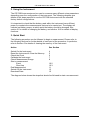
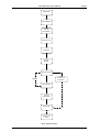
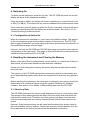
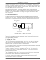
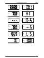
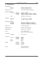
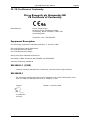
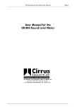
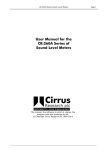
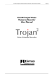
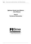
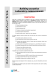
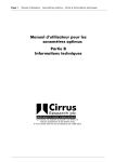
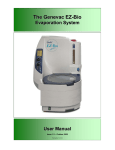
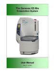
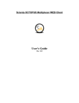
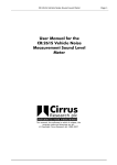
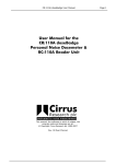
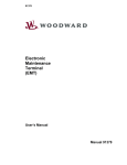
CR:700B Series User Manual
CR:700B Series User
Manual
This manual, the software to which it relates, the program
code and drawings are all:
© Copyright Cirrus Research plc 1989-2002
CR:700B Series User Manual
Page 2
The content of this manual, any illustrations, technical information and descriptions within this
document were correct at the time of going to print. Cirrus Research plc reserves the right to make
any changes neccessary, without notice, in line with the policy of continuing product developement
and improvement.
No part of this publication may be duplicated, reprinted, stored in a data processing system or
transmitted by electronic, mechanical, photographic or other means, or recorded, translated, edited,
abridged or expanded without the prior written consent of Cirrus Research plc.
No liability is accepted for any inaccuracies or omissions in this manual, although due care has been
taken to ensure that is it complete and accurate as possible.
Accessories supplied by Cirrus Research plc have been designed for use with the instrumentation
manufactured by Cirrus Research plc. No responsibility is accepted for damage caused by the use of
any other parts or accessories.
Produced by Cirrus Research plc, Acoustic House, Bridlington Road, Hunmanby, North Yorkshire,
YO14 0PH.
© Copyright Cirrus Research plc 2002
Reference Number 01/09/700B/98
Document Printing Date 21 January 2002
CR:700B Series User Manual
Page 3
1. Introduction
1.1. New Functions
Page 5
Page 5
2. Using the Instrument
Page 6
3. Quick Start
Page 6
4. Switching On
4.1. Configuration at Switch On
Page 8
Page 8
5. Resetting the Instrument and Clearing the Memory
5.1. Short Leq Data
5.2. Internal Reset Button
Page 8
Page 8
Page 9
6. Setting the Clock
Page 9
7. Calibrating the Instrument
7.1. Calibration Check
Page 10
Page 11
8. Measurement Range
8.1. Checking the Measurement Range
8.2. Changing Range during Measurements
Page 12
Page 12
Page 12
9. Pausing Measurements
Page 12
10. Measuring Data
10.1. Memory Capacity
10.2. Starting Events
10.3. Storing Short Leq Data
Page 15
Page 15
Page 15
Page 16
11. Ending a Measurement
11.1. Events
11.2. Short Leq Data
Page 17
Page 17
Page 17
12. Viewing Stored Events
12.1. Increment & Decrement Event
Page 17
Page 17
13. Switching Off
Page 18
14. Memory Backup
Page 18
15. Downloading Data
15.1. Connecting the CR:700B
Page 18
Page 18
16. Calibration
16.1. Recommended Calibrators
16.2. Procedure
16.3. Calibration Check
Page 19
Page 19
Page 20
Page 20
17. Replacing the Battery.
Page 21
18. Instrument Functions.
Page 22
CR:700B Series User Manual
18.1. Keypad
18.2. Display Functions
18.3. Available Parameters
18.4. Printout Information.
18.5. Automatic Events.
18.6. Integrators.
18.7. Exceedence Levels or Ln values.
Page 4
Page 22
Page 22
Page 24
Page 26
Page 26
Page 26
Page 27
19. Trouble Shooting
Page 28
20. Rating Plate Information.
Page 29
21. Specification.
Page 32
23. Guarantee
Page 34
24. Cirrus Research Offices
Page 34
CR:700B Series User Manual
Page 5
1. Introduction
This manual refers to the CR:700B series of data logging Sound Level Meters and
data logging dosemeters. The range of instruments in the CR:700B series are:
• CR:701B Type 2 Data Logging Personal Sound Exposure Meter (Dosemeter).
• CR:704B Type 2 Data Logging Sound Level Meter.
• CR:703B Type 1 Precision Data Logging Sound Level Meter.
These instruments replace the previous CR:700 series of instruments. In particular,
the CR:702 has been replaced by the CR:704B which has two measurement ranges
rather than the single range of the CR:702.
This manual does not refer to the previous range of CR:700 series of instruments,
although most of the functions described in this manual are available from the
previous versions.
1.1. New Functions
The additions to the CR:700B instruments are:
• Clock set available directly from keypad
• Short Leq data acquisition started with the first Event measurement
• Pause key added
• 700Setup for Windows supplied as standard
The CR:700B series of instruments are supplied with the updated version of
700Setup, now called 700Setup for Windows. This program is compatible with MSWindows (versions 3.1, 3.11 and 95), and replaces the W700Read software
previously supplied as standard with the CR:700 series. It also replaces the previous
versions of 700Setup and 700Read for MS-DOS.
CR:700B Series User Manual
Page 6
2. Using the Instrument
The CR:700B Instruments can be used to measure many different noise parameters
depending upon the configuration of the instrument. The following chapters give
details of the steps required to use the CR:700B Instrument with the standard
factory default configurations.
It is important to check that the battery used within the instrument has sufficient
power to complete the measurements that are to be carried out. The display will
indicate low battery power, at which point the battery should be changed. See
section 21 for details of changing the battery, and section 18.2 for details of display
functions.
3. Quick Start
The following procedure can be followed to begin a measurement. Please refer to
the following sections for further details of each part of the procedure. In particular,
refer to Section 5 for details of clearing the memory of the instrument.
Action
See Section
Switch On the Instrument
Reset the Instrument & Clear the Memory
Check the Clock
Calibrate the Instrument
Check Measurement Range
Start a measurement
Event
Short Leq
End Measurement
Switch Off the Instrument
Download Data
4
5
6
7
8
10.2
10.3
11
13
15
The diagram below shows the steps that should be followed to start a measurement.
CR:700B Series User Manual
Power On
Check Battery
Reset
Instrument
Check Clock
Calibrate
Check
Range
Start Event #1
Start Short
Leq Store
Repeat
Stop Event
Second
Calibration
Power Off
Download
Data
Quick Start Flowchart
Page 7
CR:700B Series User Manual
Page 8
4. Switching On
To switch on the instrument, press the On key. The CR:700B will power on and the
display will show all the characters available.
Once the power is stable, the display will revert to showing the current Sound Level
or SPL(F) in dB(A). The instrument can now be calibrated and measurements made.
If the instrument does not power up when the On key is pressed, check that there is
a battery connected and that the battery has sufficient power. See section 19 for
Trouble Shooting if problems persist.
4.1. Configuration at Switch On
When the instrument is switched on, it will revert to its default settings. This applies
to the measurement range and the default display of Sound Level. The CR:701B
Data Logging Dosemeter is a single range instrument, and therefore the selection of
the measurement range does not apply.
However, for both the CR:703B and CR:704B dual range instruments, the power on
configuration is the High range. This range is selected to allow the instruments to be
calibrated at the preferred level of 93.7dB.
5. Resetting the Instrument and Clearing the Memory
Before a new set of Event measurements can be started, or a new block of Short Leq
data stored, the instrument should be reset and then calibrated.
Please note that clearing the memory will destroy all previous data and should be
done with care.
The memory of the CR:700B instruments is powered by both the main battery and
an on-board backup supply which allows the contents to be kept over long period of
time.
Before resetting the instrument, the information contained in the memory should be
downloaded to a suitable computer using the supplied 700Setup for Windows
software. See section 15 for details of Downloading data from the CR:700B.
5.1. Short Leq Data
The CR:700B instrument can store a single sequence of short Leq time history data .
The storage of this data begins with the start of the first Event and ends when the
instrument is switched off. Therefore once this memory has been used, the data
must be downloaded and the memory cleared (Reset) before further data can be
stored.
However, Event measurements can be made and the data will be simply stored in
the next available memory location. Clearing the memory will also destroy all of the
Event data held in the instrument as well as the calibration information.
CR:700B Series User Manual
Page 9
To Reset the instrument and clear the memory, press and hold the Reset key for 5
seconds. The display will show a countdown from 5 to 0 and the instrument will then
reset. During the reset period, all of the characters of the display will be shown. After
reset, the display will revert to Sound Level.
When the instrument is reset, the unit will reload its default configuration from
EPROM in to the operating system. This allows the instrument to be rebooted if any
problems occur for example when attempting to reprogram the instrument with a
new configuration.
5.2. Internal Reset Button
In addition to resetting the instrument using the keypad, a master reset button is
available if an error occurs, such as the keypad locking. This master reset button is
located next to the RS232 socket inside the battery compartment as shown below:
RS232 Socket
Battery
Reset Button
CR:700B Battery & RS232 Connections
Pressing the reset button does not destroy the internal memory of the instrument,
unlike pressing the Reset key.
6. Setting the Clock
The CR:700B series of instruments have an internal real time clock and calendar
which is used to time and date stamp all operations carried out. These include
calibration, reset and Event and Short Leq measurements.
It is very important that the clock is set correctly before measurements are taken and
before the instrument is calibrated.
To check the status of the internal clock, press the Clock key. The layout of the
Clock key on the keypad is shown below. See section 18 for further information
regarding keypad functions.
This will display the current time of the instrument clock. If this time is correct, then
the instrument can be calibrated and measurements made.
If, however, the clock does not show the correct time, hold the clock key for 5
seconds to enter the clock set procedure.
Page 10
CR:700B Series User Manual
+5
+1
Next
Set
Clock
Clock key positions
The keys shown above are used to set the clock. Once the clock set procedure has
been started by pressing the clock key for 5 seconds, the functions shown at the top
of each key become active. The +5 and +1 keys are used to advance the current
parameter, and the Next key used to step to the next parameter. The parameters to
be set are:
Current Time (Hours)
Current Time (Minutes)
Current Month
Current Date
Current Year
Once the Year has been entered, pressing the Next key will exit from the procedure
and the clock will be set.
7. Calibrating the Instrument
It is essential that the CR:700B Instruments are calibrated before use to ensure the
accuracy of the measurements.
The CR:700B instruments are fitted with ½" microphone capsules. The instruments
therefore require an Acoustic Calibrator that can be used with this type of
microphone capsule. The Cirrus Research CR:513A or CR:512 Acoustic Calibrators
are the recommended units for use with the CR:700B Instruments.
To Calibrate the instrument, carefully insert the microphone capsule into the cavity
provided by the Acoustic Calibrator. Ensure that the capsule is correctly seated in
the cavity. Switch on the Calibrator and select the setting of 94dB. The CR:700B
Series are preset to accept a calibration level of 94dB.
Press the SPL key and allow the level to settle for 5 seconds. Once the level has
stabilised, press the Cal key. The instrument will now calibrate unless an error
occurs. See section 19 for Trouble Shooting.
CR:700B Series User Manual
Page 11
The microphones fitted to the CR:700B instruments when used with any of the
Cirrus Research plc CR:510 Series of Acoustic Calibrators require a correction of 0.3dB. Therefore the instruments will calibrate to 93.7dB, rather than 94.0dB.
Once the display shows 93.7dB, the calibration process has been completed and
the instrument may be used.
For further details regarding calibration, refer to section 16. Also refer to the manual
supplied with the Acoustic Calibrator being used for details any of calibration
corrections that may be required.
7.1. Calibration Check
Once the measurements have been completed, a calibration check can be carried
out to ensure that the instrument has not drifted during operation.
This calibration check is stored in the instrument and is displayed when the data is
downloaded. To carry out the calibration check, follow the procedure detailed above.
Once the calibration check is completed, the display will revert to the current Sound
Level.
CR:700B Series User Manual
Page 12
8. Measurement Range
The CR:703B and CR:704B Instruments have two measurement ranges. This allows
a wide range of noise levels to be measured. When the instruments are switched on
or are reset, the range is set to the default. This is the High range as standard in
both instruments.
To toggle the measurement range from high to low and vice versa, press and
release the On/Hi-Lo key. The display will show the new range and then revert to
Sound Level.
8.1. Checking the Measurement Range
To check the current range, press and release the Off/Range key. This will show the
current range, either HI or LO indicating the High or Low measurement ranges.
8.2. Changing Range during Measurements
If the measurement range is changed during an Event, the measurement will be
stopped. If the instrument is storing Short Leq data when the range is changed, the
storage will not be affected and will continue until the instrument is either reset or
switched off.
9. Pausing Measurements
The Pause key function has been added to those available from the CR:700B
Series. The Pause key acts as a data inhibit function and will affect the instrument in
different ways according to the operating status of the instrument when the key is
pressed. Pause mode is entered by pressing the Pause key, and is released by
pressing it again.
As an example, shown below are three different cases of the Pause Mode. These
are:
Example 1 Pause during an Event.
If the Pause Key is pressed during an Event, the noise data occuring during the
Pause will not be included in the information for the Event. Also, the run time of the
Event will be adjusted accordingly to remove the time in Pause mode.
Example 2 Pause during subsequent Events.
The Pause key is pressed during an Event and then the Event is stopped with the
instrument still in Pause Mode. As above, any data occurring when the instrument is
in Pause mode will be removed from the calculated values stored for the Event. A
new Event is started with the instrument still in Pause mode by pressing the Run
Key. The Event will start, but data will be inhibited until the Pause key is pressed
again to end the Pause mode.
Example 3 Pause during Automatic Events.
CR:700B Series User Manual
Page 13
When the instrument is programmed to perform automatic Events, the Pause key
will not affect the starting and stopping of the Events. However, as in the two other
examples above, any data occurring during the Pause mode will be removed from
the calculated values. The duration of the Events will also be adjusted according to
the amount of time the instrument has been in Pause mode during the Event.
See Section 22 for the information shown on the display when the instrument is in
Pause mode.
The diagram below shows how the Pause key affects the data during an Event as
described in the examples above.
CR:700B Series User Manual
Page 14
Instrument Paused
Data Inhibited
Event Running
Time
Example 1 - Pause Key Pressed During Single Event
Instrument Paused
Data Inhibited
Event Running
Event Running
Time
Example 2 - Pause Key Pressed During Manual Events
Instrument Paused
Data Inhibited
Event Running
Event Running
Time
Example 3 - Pause Key Pressed During Automatic Events
Examples of Data Inhibit with the Pause Key
CR:700B Series User Manual
Page 15
10. Measuring Data
Once the instrument has been reset and the clock set, it is ready for measurements
to be made. The CR:700B instruments are capable of storing two different forms of
data. These are Events and Short Leq data.
The Events consist of either manual or automatic starting and stopping of
measurements. Each measurement has associated with it parameters that can be
changed by user from the factory default, but typical data may include:
Event Number
Start Time
Run Time
Leq
SEL
LEP,d
L10
L90
Peak
Max
Min
Each of these values would be calculated for each Event with the Run Time
determined either by the operator when a manual Event is activated, or by the
instrument having been programmed by the 700Setup for Windows Software. The
calculation of these parameters can be affected by the Pause Key. See section 9
for detail of the operation of the Pause key.
The Short Leq data is a time history or noise profile that can be stored by the
instrument. By using Short Leq, the instrument is storing all of the noise energy that
occurred rather than samples of the actual noise, such as SPL(F). This allows
information to be calculated at a later date with assured accuracy. The duration of
the Short Leq samples can be altered by the 700Setup for Windows software, with
the range from 62.5mS to 16 seconds being available.
10.1. Memory Capacity
The internal memory of the CR:700B instruments is shared between the Events and
the Short Leq data. Therefore, increasing the number of Events that can be stored
will reduce the amount of space available for the Short Leq data, and vice versa. The
number of Events that can be stored can be altered by using the 700Setup for
Windows software. The program will also determine the amount of time of Short Leq
Data that can be stored at the selected Short Leq duration.
The instruments are supplied with a default configuration which allows for a number
of Events and Short Leq data to be stored. These values are such that the maximum
amount of Short Leq can be stored along with a reasonable number of Events. These
values can be viewed by the 700Setup for Windows Software.
10.2. Starting Events
An Event can be started by either pressing the Run key, or by an automatic Event
Page 16
CR:700B Series User Manual
function that has been programmed into the instrument by the 700Setup for
Windows software.
When the Run key is pressed, the display will show the current Event number, such
as 1E if the Event is the first in the memory. The display will then revert to the
current Sound Level. The display will also show a Run annunciator on the left side
when an Event is running. See section 18.2 for details of the display functions.
10.3. Storing Short Leq Data
Storage of Short Leq data starts with the first Event after the instrument has been
reset. If the instrument shows 1E when the Run key is pressed, the Short Leq will
begin to be stored. Data will continue to be collected until the instrument is switched
off. The data storage will not begin again until the instrument is reset again.
The diagram below shows how the Short Leq starts and stops with the Events and
the Power Off key.
Power On
Reset
Calibrate
Power Off
Event #1
Event #2
Event #3
Short Leq Data
Time
Example 1 - Short Leq Data Stored During 3 Events
Power On
Reset
Calibrate
Power
Off On
Event #1
Power
Off On
Event #2
Power Off
Event #3
Short Leq Data
Time
Example 2 - Short Leq Data Stored During Event #1 Only
CR:700B Series User Manual
Page 17
Ensure that any data contained within the instrument has been downloaded before
resetting the instrument.
11. Ending a Measurement
11.1. Events
An Event can be stopped by either pressing the Stop key, or by an automatic Event
function that has been programmed into the instrument.
When the Stop key is pressed, the display will show the Event number and then
revert to showing the current Sound Level. The Run annunciator will be removed
from the display.
When an automatic function stops an Event, the display will revert to the current
Sound Level.
11.2. Short Leq Data
The storage of Short Leq is stopped when either the instrument is switched off, or
reset. Storage of short Leq data is also stopped when the range of the instrument is
changed.
12. Viewing Stored Events
When Event data has been either stored at the end of an Event, or during an active
Event measurement, the calculated values can be displayed by the instrument. Any
key that has been defined which gives Event information will display the relevant
data for that measurement.
As an example, pressing the Event Time key during a measurement will display the
current duration of that Event. However, many of the display functions do not update
automatically and will only display the value at the time that the key is pressed.
Pressing and holding the Event Time key will update the display. This applies for
most of the Event keys.
12.1. Increment & Decrement Event
All of the CR:700B Instruments are supplied as standard with an Event Increment
key. This allows the user to step through the stored measurements and review the
calculated values for the chosen Event. When the user reaches the last stored
Event number, the instrument with cycle back to the first stored Event. See section
18.2 for an example of the display shown when selecting an Event.
When the required Event number is displayed, pressing the Event keys such as
Event Leq or Event Peak will display the measured value for that Event.
Also available as a key function is Event Decrement which will step down through
the stored Events. As with the Event Increment key, the Events will cycle when the
first Event is reached.
CR:700B Series User Manual
Page 18
13. Switching Off
The CR:700B Instruments are switched off by pressing and holding the Off key for 5
seconds. The display will count down from 5 to 0 and the instrument will then switch
off. See section 18.2 for details.
If the instrument is currently measuring an Event, the measurement will stop. If the
instrument also storing Short Leq data, the acquisition of this data will also stop.
14. Memory Backup
The contents of the memory will be retained provided the reset key is not pressed
and there is sufficient power within the internal backup battery. This battery will be
charged from the main battery and will support the memory for up to 5 days after the
main supply is removed. If the backup battery is discharged, it will take
approximately 5 days to recharge. Care should be taken to ensure that a battery is
connected continuously after the backup battery has been discharged. The backup
battery will continue to take power from the main battery even when the instrument
is switched off.
15. Downloading Data
Data can be downloaded from the CR:700B Instruments by using the supplied
700Setup for Windows software program. In addition, data can be copied directly to
a suitable serial printer if connected.
Contact your local agent or Cirrus Research plc for details of connecting serial
printers to the CR:700B Instruments.
Please note that the CR:700B will not communicate if the battery is low. Replace the
battery before downloading data if the BATT annunciator is showing.
15.1. Connecting the CR:700B
All of the CR:700B Instruments are supplied with an RS232 download cable. One
end of this cable is a standard 9 pin DIN Socket which should be connected to a
suitable COM port on a PC. The other end of the cable is a Mini-Din plug which
should be connected to the RS232 socket of the instrument.
Remove the battery compartment cover to access the RS232 socket shown below.
CR:700B Series User Manual
Page 19
RS232 Socket
Battery
Reset Button
CR:700B Battery & RS232 Connections
Connect the supplied ZL:700 cable to the instrument. The instrument is now ready
for communication with the 700Setup for Windows software.
Ensure that the 700Setup for Windows software has been loaded on to the PC.
Please refer to the information supplied with the 700Setup for Windows software for
installation details.
The instrument must be switched on before communication can be made between
the instrument and the 700Setup for Windows software. See section 19 for
troubleshooting if problems are encountered when downloading data.
16. Calibration
It is vital that the calibration of any Sound Level Meter is checked before and after
each measurement. If this is done, it is reasonable to assume that the calibration
during the measurement was correct. If this is not done, you will not subsequently be
able to be certain that the instrument calibration was correct and you can never be
certain the sound level was as measured.
The Sound Level Meter is calibrated acoustically using an external reference, e.g
the Sound Level Calibrator CR:513A, which is placed over the microphone. The
calibrator generates a stabilised Sound Pressure Level of 94dB re 20µPa (+- 0.3dB)
at a frequency of 1kHz.
16.1. Recommended Calibrators
The normal field calibrator is the CR:513A, although the CR:511E and CR:512 units
are also compatible with the CR:700B series. All of these Acoustic Calibrators meet
the requirements of IEC 942. The gain of a Sound Level Meter at 1kHz is the same
for all weighting networks and thus it can be calibrated on dBA. However, a
calibration correction is required for different microphones.
The CR:701B and CR:704B instruments are fitted with a standard Cirrus ½"
microphone capsule, whilst the CR:703B is fitted with the MK:224 capsule. Both of
these microphones have a calibration correction of -0.3dB.
CR:700B Series User Manual
Page 20
This correction is required because of the differing pressure and free field
sensitivities of the microphones.
The default calibration value of 93.7dB can be altered by the user with the 700Setup
for Windows software, or by Cirrus Research plc when the instrument is
manufactured. However, it is not recommended that this value is changed unless the
user is familiar with the operation of microphones and Acoustic Calibrators. If a new
type of microphone capsule is fitted, then the calibration correction may need to be
altered. Please contact Cirrus Research plc for further details.
16.2. Procedure
Remove any dust cover or windshield from the microphone, and fit the correct
adaptor to the Acoustic Calibrator.
Check that the battery in the Sound Level Meter is adequate. If not, replace the
battery before calibrating the instrument.
Turn on the calibrator and check that the battery condition is adequate in the
calibrator by turning it on. A 1kHz signal should be audible and if the Green LED is
lit, the calibration signal is accurate. This applies to the CR:510 series of calibrators.
Place the calibrator over the microphone and select a suitable measurement range
on the Sound Level Meter where applicable. This range should be the one that
covers the 93.7dB calibration level. Press the SPL key and allow the level to settle
for 5 seconds.
Press the CAL key on the keypad, and the displayed level should shift to 93.7dB if
the calibration level is within the range accepted by the instrument. If it is not, the
display will show “2 HI” or “2 LO”.
If this cannot be achieved, the microphone, instrument or Acoustic Calibrator may be
at fault and a check should be made with Cirrus Research.
When the instrument displays 93.7dB, the calibration process is complete and the
calibration adjustment has been written into the internal memory of the instrument.
This value will be held as the current calibration level until the instrument is reset or
reprogrammed.
16.3. Calibration Check
Once the measurements have been completed, a calibration check can be carried
out to ensure that the instrument has not drifted during operation.
This calibration check is stored in the instrument and is displayed when the data is
downloaded. To carry out the calibration check, follow the procedure detailed above.
CR:700B Series User Manual
Page 21
17. Replacing the Battery.
Power to the CR:700B series is supplied by one 9V battery. The specification of
these batteries is IEC 6F22 or NEDA 1604. This is commonly known as PP3 in the
UK.
The use of calculator quality batteries is recommended as these have a better
exchange rate of current versus life. Mercury batteries can be used in the
instrument . The battery is changed by removing the black cover at the base of the
instrument.
Ensure that the instrument is switched off, and remove the battery from the clip.
Connect a new battery to the clip. Ensure that the battery is connection with the
correct polarity, and push the battery back inside the instrument. Slide the battery
cover back on to the instrument.
RS232 Socket
Battery
Reset Button
CR:700B Battery & RS232 Connections
Page 22
CR:700B Series User Manual
18. Instrument Functions.
18.1. Keypad
The CR:700B series of instruments have an internal microprocessor. This allows the
instrument to support a wide range of measurement functions. Over 100 individual
measurement and operation functions are available, and any one can be attached to
the keys of the keypad. There are restrictions however in the placement of the
Power On key which must always be located on the bottom row of the keypad,
second position from the right as shown below. Also, the Clock key cannot be
moved from the position shown below.
Clock
On
Instruments are supplied with a factory default keypad, but this can be
reprogrammed either by Cirrus Research , or by the user with using the 700Setup
for Windows software supplied as standard with the instrument. Please refer to the
700Setup for Windows software program for details of changing the configuration.
18.2. Display Functions
The display of the CR:700B Instrument is used to show the current noise level as
well as other parameters such as the current time and if the instrument is in pause
mode.
Shown below with brief descriptions is a summary of the more common display
configurations that may be seen.
Page 23
CR:700B Series User Manual
BATT
RUN
O.L.
%
dB
Pa 2 H
All Characters shown (during Reset)
RUN
Event Number (Event Increment)
dB
Noise Level or Calculated Value (Event Running)
RUN
Range Check or Change
dB
Pause Mode (Event Running)
RUN
Countdown to Power Off
dB
Pause Mode (Event Running)
RUN
Countdown to Reset (Event Running)
RUN
Clock Display
Coundown to Reset (Short Leq & Event Running)
BATT
RUN
Run Key Pressed Showing Event Number
dB
Battery Low (Event Running)
CR:700B Series User Manual
Page 24
18.3. Available Parameters
Detailed below are the measurement parameters and operating functions that are
available from any of the CR:700B instruments.
As detailed above, these functions can be programmed into the instrument and
assigned a key on the keypad. A new layout can be printed and inserted into the
keypad on the front of the instrument.
Different instrument configurations can be created and loaded into the instrument
when required by the 700Setup for Windows Software program.
SPL
ON
Turns on the CR:700B.
OFF
If pressed continuously for 5
seconds, it counts down from "O-5"
to "O-1", followed by a blank display.
ON
OFF
Toggles the CR:700B on and off as
above.
The first time after reset, this key
calibrates the CR:700B. The display
shows calibration level.
Run
Turns on the RUN annunciator and
starts accumulating Event data.
CAL
Time
The time of the initial calibration in
hours and minutes.
Stop
Turns off the RUN annunciator and
saves the Event data.
CAL
Level
The last calibration level.
Pause
Pauses the current Event until pause
is pressed again.
2CAL
Time
The time of the last calibration in
hours and minutes.
Run
Stop
Clock
If the clock has been set, it displays
the current time. If the clock has not
been set, it displays the time since
reset or turn on. Hold for 5 seconds
to set clock
Toggles the run and stop in a single
key.Release the key within 1 second
for proper operation.
Event
Displays the Event number used for
all the Event keys.
Event
Dec
Decrements the Event number used
for the Event keys.After Event
number 1 it returns to the highest
numbered Event.
Event
Inc
Increments the Event number used
for the Event keys. After the highest
numbered Event it returns to the
Event number 1.
Reset
If pressed and held for 5 seconds
the CR:700B is reset.
Print
Prints out ASCII text for hard copy to
a serial printer.
Short
CAL
Sound level with an either Fast or
Slow time constant. Updates each
second until another key is pressed.
The current Short Leq being Leq
acquired. Updates each second until
another key is pressed.
Run
Time
The total time the RUN annunciator
has been on and the CR:700B has
been accumulating data since the
last reset.
Event
The time the CR:700B RUN Time
annunciator has been on and the
Run accumulating Event data since
the last time run was pressed.
Stop
Time
The time since the last reset when
the CR:700B was stopped and not
accumulating Event data.
UL
Time
The total time the level has been
greater than the upper threshold
level during RUN.
OL
Time
The total time the CR:700B has been
overloaded during run.
CR:700B Series User Manual
Page 25
Total or Event data.
The Event keys display data only for a single Event. Other keys display data for the
total time the RUN annunciator is on and the unit is accumulating Event data. The
following keys may be either Event or total keys.
Event
Peak
The highest instantaneous pressure
level.
Event
Max
The maximum level with an F (fast)
or S (slow) time constant.
Event
Min
The minimum level with a F (fast) or
S (slow) time constant.
Peak
Time
The time the highest peak occurred
in hours and minutes. Not defined for
Events.
Max
The time the maximum level Time
occurred in hours and minutes.Not
defined for Events.
Min
Time
The time the minimum level occurred
in hours and minutes. Not defined for
Events.
Event
Dose
The accumulated dose for integrator
1,2 or 3
Event
Est %
The estimated dose for integrator 1,2
or 3
Event
Exp
The exposure for integrator 1,2 or 3
In Pascal squared hours.
Event
The estimated exposure for
integrator Est Exp
1,2 or 3
Event
The exposure for integrator 1,2 or 3
Exp Pa2s in Pa2s
Event
The equivalent sound level for Leq
integrator 1,2 or 3
Event
The sound exposure level for SEL
integrator 1,2 or 3
Event
The time weighted average for TWA
integrator 1,2 or 3
Event
Lep,d
The equivalent sound level per day
for integrator 1,2 or 3
Event
Lnn
The level that has been exceeded
for nn percent of the time. (nn) is a
number from 01 to 99.
Ln
Cycle
Cycles through up to 8 Ln's. The
display shows the Ln number
followed by the level.
CR:700B Series User Manual
Page 26
18.4. Printout Information.
It is possible to configure the printout to include only those lines desired in the final
report. This is performed by the 700Setup for Windows Software. The Event line will
generate multiple lines of printout for each Event.
The CR:700B series are supplied with a default setting for the printout. Please refer
to the 700Setup for Windows software for details.
18.5. Automatic Events.
Events can be started and stopped manually from the key pad with the RUN and
STOP keys or the CR:700B can automatically start and stop Events. This function is
provided by the 700Setup for Windows software program supplied as standard with
all CR:700B instruments.
The options on starting and stopping Events include:
1.
Start or stop an Event at a preset clock time.
ie Start at 0800, stop at 1600
2.
Start or stop an Event after a preset duration.
ie Start after 5 minutes or stop for 1 hour and 30 minutes.
3.
Start or stop an Event at next time evenly divisible by clock time.
ie Start at the next 15 minutes. Minutes and hours must divide into 60 and
24 respectively to give predicable results.
4.
Turn off CR:700B.
5.
Turn off CR:700B and turn back on at preset clock time.
6.
Repeat a series of Events.
ie Repeat a preset number of 15 minute measurements
Up to 6 automatic Events can be strung together with repeats.
18.6. Integrators.
Integrators are used to store data required to calculate parameters such as
integrated sound levels, dose, and exposure measurements. The CR:700B contains
3 separate integrators. Each integrator can be configured to do the following:
1.
Function with a Fast, Slow, no time constant or LATm (3 or 5 seconds)
2.
Use any exchange rate from 3.0 to 6.0 dB.
3.
Ignore sound levels below a threshold.
4.
Calculate dose with a user defined criterion level.
CR:700B Series User Manual
5.
Page 27
Calculate dose and estimated dose, exposure, TWA and LEP,d with a
selectable criterion time.
The 3 integrators can be selected from
1.
2.
3.
4.
5.
6.
7.
8.
OSHA
HCA
DOD
INT1
INT2
INT3
3 dB
LATm
(USA Occupational Health)
(Hearing Conservation Amendment)
(USA Dept of Defence)
User defined
User defined
User defined
(Equal Energy for EC etc.)
(German standard measurement) 5s or 3s
All of the integrator functions can be configured using the supplied 700Setup for
Windows software.
18.7. Exceedence Levels or Ln values.
Exceedance levels, or Ln values, measure the level that is exceeded a given
percentage of the time. For example, L10 is the level that is exceeded 10 % of the
time. The CR:700B can calculate 8 Ln numbers of any percentage from 1 to 99.
The 8 Ln's are calculated for each Event.
The exceedence levels can be changed using the supplied 700Setup for Windows
software.
Page 28
CR:700B Series User Manual
19. Trouble Shooting
Symptom
Possible Cause
Solution
Instrument will not switch on
No Battery
Battery Flat
Internal Error
Fit New Battery
Fit New Battery
Press Internal Reset
Key
Instrument will not Calibrate
Battery Low
Calibrator Not Working
Microphone Not Connected
Microphone Damaged
Fit New Battery
Check Calibrator
Connect Microphone
Contact Agent or Cirrus
Research plc
Press Internal Reset
Key
Internal Error
During Calibration
Instrument displays 2 LO
During Calibration
Instrument displays 2 HI
Instrument fails to download
Signal Too Low
Calibrator Not Working
Select 94dB Level
Check Calibrator
Signal Too High
Select 94dB Level
Instrument Not Switched On
Download Cable Not Connected
Switch on Instrument
Connect Download
Cable
Check Software
Configuration
Software Communication Error
Data has incorrect time & date
Clock not set
Set Clock before using
instrument
No Calibration Level in Data
Instrument Not Calibrated
Calibrate Instrument
before use
Instrument Switches Off when
downloading Data
Battery Low
Fit New Battery
Short Leq Data has not been stored
Instrument not reset before user
Reset instrument &
start Event #1
Keypad not responding
Keypad Locked
Use software to unlock
keypad
Press Internal Reset
Key
Internal Error
CR:700B Series User Manual
Page 29
20. Rating Plate Information.
The CR:700B series meets IEC 651 (BS 5969) and IEC804 (BS) Types 1 or 2,
depending on the microphone fitted. The specifications IEC 651 and IEC 804 require
that this manual provides detailed information to verify that the specifications are
met. While much of the data required is in the body of this manual, the points required to be detailed are listed below in the order in which they occur in the IEC
specification. The numbers marked after to IEC number refer to that documents
paragraph numbers for reference.
IEC 804/651 11.2.1
The microphone is an electret condenser microphone mounted on the case. To
meet IEC Type 1 or 2 the unit should be fitted on a tripod.
IEC 804/651 11.2.2
The reference direction of incidence is parallel to the case as marked with an arrow
on the cone.
IEC 804/651 11.2.3
The range of measurement for Leq and SPL measurement with a standard assembly
is:CR:701B
67 dB(A) to 130 dB(A)
CR:704B
32 dB(A) to 130 dB(A)
CR:703B
25 dB(A) to 125 dB(A)
The range of measurement for Peak measurement with a standard assembly is:CR:701B
90 dB(C) to 143 dB(C) Peak
CR:704B
90 dB(C) to 143 dB(C) Peak
CR:703B
90 dB(C) to 143 dB(C) Peak
IEC 804 11.2.4
Linearity Range:
CR:701B & CR:704B
CR:703B
50dB below Overload
60dB below Overload
Pulse range:
CR:701B & CR:704B
CR:703B
+3dB Above Linearity Range
+3dB Above Linearity Range
IEC 804 11.2.7 & IEC 651 11.2.4
The reference sound pressure is 1 Pa (94dB).
IEC 804 11.2.5
Not Applicable
IEC 651 11.2.5
'A' weighting is provided.
Peak is displayed in dB(C) only.
IEC 651 11.2.6
"F" and "S" response are fitted with a 'Hold' on the max RMS value of each. Peak is
fitted.
IEC 804 11.2.9 & IEC 651 11.2.7
The effect of vibrations is such that 5g in any direction will not cause a reading on
CR:700B Series User Manual
Page 30
scale.
IEC 804 11.2.10 & IEC 651 11.2.8
The unit is unaffected by a field of 80 A/m
IEC 804 11.2.11 & IEC 651 11.2.9
The unit remains within specification at any temperature between -10 and +50
degrees Celsius. It may be stored safely between -20 and +70 degrees Celsius.
IEC 651 11.2.10
The operators must remove themselves from the measuring field by putting the unit
on a tripod. However, if this is not possible the unit will meet Type 2 specifications
when held at arms length.
IEC 804 11.2.12 & IEC 651 11.2.11
The unit will meet its specification at any humidity from 0 to 99 % RH.
IEC 804 11.2.13 & IEC 651 11.2.12
Maximum storage temperature of +60 degree (+50 degree extended period) and
50% RH should be observed.
IEC 804 11.2.14 & IEC 651 11.2.13
There is no provision for a microphone extension cable on the standard CR:701B
and CR:704B units. The CR:703B can be fitted with extension cables, and if the
extension cable option is in use, Cirrus Research cables up to 10 meters long will
not affect the calibration.
IEC 804 11.2.15 & IEC 651 11.2.14
The UA:237 windscreen has negligible effect on calibration up to 12.5kHz.
IEC 804 11.2.16 & IEC 651 11.2.15
The use of a pistonphone (PF 101B) is required to ensure long term compliance.
For short term compliance the CR:513A may be used but this should be checked
against a secondary or transfer standard annually.
IEC 804 11.2.17 & IEC 651 11.2.16
The observer should be behind the case for optimum results. The operator should
never be at the side or in front of the unit.
IEC 804 11.2.18 & IEC 651 11.2.17
Not applicable.
IEC 804 11.2.19 & IEC 651 11.2.18
The limitations on the electrical impedance that may be connected to the output
connectors:- Any real, positive impedance of zero ohm upwards.
IEC 804 11.2.6 & IEC 651 11.2.19
The reference frequency used for calibration is 1kHz.
IEC 804 11.2.8 & IEC 651 11.2.20
There is one range provided on the CR:701B and therefore this is the reference
range. For the CR:704B & CR:703B the high range is the reference range.
CR:700B Series User Manual
Page 31
IEC 804 11.2.20 & IEC 651 11.2.21
The warm up period is 1 minute.
IEC 804 11.2.21
The settling time before valid Leq readings are obtained is one minute.
IEC 804 11.2.22
The nominal battery life is 12 hours continuous use.
IEC 651 11.2.22t
Not applicable.
IEC 804/651 11.2.23
Refer to microphone data.
IEC 804/651 11.2.24
Refer to microphone data.
IEC 804/651 11.2.25
Dummy microphone impedance is 18 pF in series with 50ohm.
IEC 651 11.2.26
Primary Indicator range is between 13dB and 23dB below the overload indication.
IEC 651 11.2.27
There is no autorange on the CR:700B series.
IEC 804 11.2.26 & IEC 651 11.2.28
+1dB at all frequencies greater than or equal to 31.5Hz.
IEC 804 11.2.27
The instrument can be factory set for free field or diffuse field use.
IEC 804 11.2.28
The indicator range is identical to the linearity range of section IEC 804 11.2.4
IEC 651 11.2.28
The CR:701B should be mounted away from the microphone. The microphone
should be mounted remotely.
The CR:704B should be mounted on a tripod.
The CR:703B should be mounted on a tripod with the preamplifier removed and
mounted remotely.
CR:700B Series User Manual
Page 32
21. Specification.
Standardisation
IEC 651
IEC 804
Defined by Microphone Type
Defined by Microphone Type
Microphone Type
½" Prepolarised Electret Condenser
Measurement Range
SPL & Leq
CR:701B
CR:704B
CR:703B
67dB(A) to 130dB(A)
32dB(A) to 100dB(A) , 60dB(A) to 130dB(A)
25dB(A) to 95dB(A) , 55dB(A) to 125dB(A)
Peak
143dB(C) for all instruments
Frequency
Time
‘A’ for SPL & Leq, ‘C’ for Peak
‘F’ (Fast), ‘S’ (Slow), Short Leq
Weighting
Measurement Storage
CR:701B
CR:704B
CR:703B
256 Events. 25,000 Short Leq elements
256 Events. 25,000 Short Leq elements
2,500 Events. 100,000 Short Leq Elements
Display Type
3 ½ Digit LCD Display
Display Functions
Defined by keypad functions
Display Flags
Batt, Run, OL, %, dB, Pa2h
Power
9v 6F22 (NEDA 1604)
External Powet via RS232 socket
Temperature
Operating
-10"C to +50"C
Dimensions
Length
CR:701B
CR:704B
CR:703B
150mm
225mm
255mm
75mm
25mm
CR:701B
CR:704B
CR:703B
300 gms
410 gms
450 gms
Width
Depth
Weight
Output
RS232 via DIN Socket
Optional AC Output
CR:700B Series User Manual
Page 33
22. CE Certificate of Conformity
Cirrus Research plc Hunmanby UK
CE Certificate of Conformity
Manufacturer:
Cirrus Research plc
Acoustic House, Bridlington Road
Hunmanby, North Yorkshire, YO14 0PH
United Kingdom
Telephone +44 1723 891655
Equipment Description
The following equipment manufactured after 1st January 1996:
CR:701B Personal Noise Dosemeter
CR:704B Sound Level Meter
CR:703B Sound Level Meter
Along with their standard accessories
According to EMC Directives 89/336/EEC and 93/98/EEC
meet the following standards
EN 50081-1 (1992)
Generic emission standard for residential, commercial and light industry
EN 50082-1
RF immunity implies that sound level indications will not be affected by more
than ±0.5dB at a background level of 74dB(A) or less.
Signed
S. O’Rourke
Director
Dated 1st January 1996
Warranty Information.
1. This document is a summary of the full warranty document and explains the Cirrus
Research plc warranty in ordinary English; not in legal or complex terms.
2. The warranty covers any acoustic instrument such as a sound level meter, acoustic
calibrator, real time acoustic analyser or personal sound exposure meter (dosemeter)
manufactured by Cirrus Research plc after 1st September 2011.
3. The warranty covers all faults on the instrument except the microphone for the period
defined in para (4) below, including minor accidental damage except to the microphone.
4. The period of the warranty is 2 (two) years or 104 weeks from the date of purchase as a
new instrument from Cirrus Research plc or their formally approved distributors OR 130
weeks from the date the instrument passed its final manufacturing inspection at Cirrus
Research plc - whichever is the shorter.
5. Any rechargeable battery only has the battery manufacturer’s one year warranty however
there will be a reduced charge for replacing rechargeable batteries during the annual
“Routine Verification” process. (Commonly referred to as “Annual Recalibration”)
6. No warranty is offered for used equipment unless a special arrangement is made and a
written confirmation of the warranty is given by Cirrus Research plc.
7. On completion of the routine verification by Cirrus Research plc, the instrument will
automatically be given an additional free one year warranty.
8. There will be a charge for this routine verification and the price is published in the Service
Price List.
9. The customer is responsible for all shipping, duty and other charges relating to the
servicing and calibration of the instruments.
10. It follows that should the instrument be routinely verified by Cirrus Research plc every
year, the warranty is effectively continuous to a maximum of 15 (fifteen) years from the
date of purchase.
11. Cirrus Research endeavours to ensure stocks of instrument components for the full
fifteen year period but do not guarantee to do so as certain components do become
obsolete or discontinued.
12. If a sub-component becomes obsolete and stocks are depleted then Cirrus Research will
endeavour to facilitate a repair but will not offer the same length guarantee.
13. In the event of any dispute on the terms of the warranty Cirrus Research plc will accept
pendulum arbitration by the United Kingdom Institute of Acoustics Ltd.
14. The warranty does not in any way reduce any legal right of the buyer or user of the
sound level meter; it is in addition to all legal rights determined by the European Union.
Cirrus Research Offices
The addresses given below are the Cirrus Research plc offices. Cirrus Research plc also have
approved distributors and agents is many countries worldwide. For details of your local
representative, please contact Cirrus Research plc at the address below. Contact details for
Cirrus Research authorised distributors and agents are also available from the Internet Web site
at the address shown below.
Main Office
Cirrus Research plc
Acoustic House
Bridlington Road
Hunmanby
North Yorkshire
United Kingdom
YO14 0PH
Telephone:
Fax:
E-mail:
Web Site:
+44 (0)1723 891655
+44 (0)1723 891742
[email protected]
www.cirrusresearch.co.uk
Germany
Cirrus Environmental
Cirrus Research plc Deutschland
Arabella Center
Lyoner Strasse 44 – 48
D-60528 Frankfurt
Germany
Unit 2 Bridlington Road Industrial Estate
Hunmanby
North Yorkshire
YO14 0PH
United Kingdom
Tel: +49 (0)69 95932047
Fax +49 (0)69 95932049
Tel:
+44 (0) 1723 891722
Email: [email protected]
Web: www.cirrus-environmental.com
Email:
Web:
[email protected]
www.cirrusresearch.de
Spain
CIRRUS RESEARCH S.L.
Travessera de Gracia, 62 4° 7ª
08006 Barcelona
SPAIN
Tel:
Email:
Web:
(34) 933 622 891
[email protected]
www.cirrusresearch.es