1
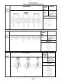
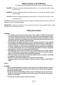
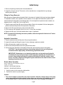
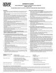
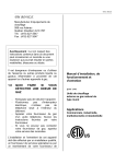
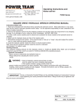
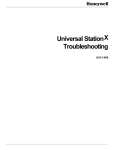
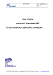
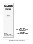
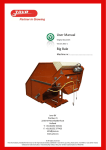
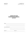
User Manual for:
EP18 Series
EP211 Series
Electric-Powered
EP18 & EP211 Series
Two-Stage Hydraulic Pump
Rev. 0
May 2014
Table of Contents
Description. . . . . . . . . . . . . . . . . . . . . . . . . . . . . . . . . . . . . . . . . . . . . . . . . . . . . . . . 2
PE18 / 211 Series Electric/Hydraulic Pumps . . . . . . . . . . . . . . . . . . . . . . . . . . . 2
Control Valves. . . . . . . . . . . . . . . . . . . . . . . . . . . . . . . . . . . . . . . . . . . . . . . . . . . . . .3
Safety Symbols and Definitions. . . . . . . . . . . . . . . . . . . . . . . . . . . . . . . . . . . . . . . . . .5
Safety Precautions. . . . . . . . . . . . . . . . . . . . . . . . . . . . . . . . . . . . . . . . . . . . . . . . . . .5
Initial Setup. . . . . . . . . . . . . . . . . . . . . . . . . . . . . . . . . . . . . . . . . . . . . . . . . . . . . . . .9
Operating Instructions. . . . . . . . . . . . . . . . . . . . . . . . . . . . . . . . . . . . . . . . . . . . . . . .12
Performance Specifications. . . . . . .. . . . . . . . . . . . . . . . . . . . . . . . . . . . . . . . . . . . . .14
General Maintenance. . . . . . . . . . . . . . . . . . . . . . . . . . . . . . . . . . . . . . . . . . . . . . .. .15
Troubleshooting Guide. . . . . . . . . . . . . . . . . . . . . . . . . . . . . . . . . . . . . . . . . . . . . . ..18
Page 2
Description
The EP18 series hydraulic pumps are designed to have a maximum of 690 bar (10,000 psi) at
a flow rate of 260 cc/min (16 cu. in/min). A pump can be valved for use with either single- or
double-acting cylinders.
The EP211 series pump all the same features as the EP18-series. The EP211series is equipped
with a 1.12 kW (½ HP) 2,880 RPM electric motor where the EP18-series is equipped with a 0.37
kW (½ HP) 2860 RPM electric motor. All pumps come fully assembled, less fluid, and ready for
work.
EP18 / 211-Series Electric / Hydraulic Pumps
The 17 series uses an induction motor. Refer to the Performance section of this manual for motor ratings.
Electric Motor
The EP18-series pumps are equipped with 0.37 kW (1/2 hp), 2860 rpm, single-phase, Brushless,
induction motor; 3M remote control cord. Low amperage draw; small generators and low amperage
circuits can be used as power source. Extremely quiet noise level (67-81 dBA).
The EP211-series pumps are equipped with 1.12 kW, 2880 rpm, single-phase, Brushless, induction motor.
Figure 1. EP18D
Figure 2. EP211D
Page 3
Control Valves
Max. Capacity: 690 Bar (10,000 PSI)
Valve Function
Use with
Valve No.
Cylinder
Type
Single- & BP423 4-way,3double- position, pump
mounted manual
acting
EP18D
EP211D
detented
Diagrams
Valve Function
Use with
Cylinder
Type
Single
acting
EP18S
EP211S
Valve No.
B1014 2-way,2position,pump
mounted manual
detented
Diagrams
Valve Function
Use with
Cylinder
Type
Single
acting
EP18SS
EP211SS
Valve No.
18-471-217 3way,2-position,
Pump mounted
solenoid operated,
normally closed
Diagrams
Table 1. Pump Configurations
Page 4
Safety Symbols and Definitions
The safety signal word designates the degree or level of hazard seriousness.
DANGER: Indicates an imminently hazardous situation which, if not avoided, will result in death
or serious injury.
WARNING: Indicates a potentially hazardous situation which, if not avoided, could result in death
or serious injury.
CAUTION: Indicates a potentially hazardous situation which, if not avoided, may result in minor
or moderate injury.
CAUTION: Used without the safety alert symbol indicates a potentially hazardous situation which, if not
avoided, may result in property damage.
IMPORTANT: Important is used when action or lack of action can cause equipment failure, either
immediate or over a long period of time.
Safety Precautions
WARNING:
• The following procedures must be performed by qualified, trained personnel who
are familiar with this equipment. Operators must read and understand all safety
precautions and operating instructions included with the pump. If the operator cannot
read these instructions, operating instructions and safety precautions must be read
and discussed in the operator's native language.
• These products are designed for general use in normal environments. These products
are not designed for lifting and moving people, agri-food machinery, certain types of
mobile machinery, or in special work environments such as: explosive, flammable, or
corrosive. Only the user can decide the suitability of this product in these conditions
or extreme environments. Power Team will supply information necessary to help make
these decisions. Consult your nearest Authorized Dealersy.
•
Safety glasses must be worn at all time by the operator and anyone within sight of
the unit. Additional personal protection equipment may include: face shield, goggles,
gloves, apron, hard hat, safety shoes, and hearing protection.
• The owner of this tool must ensure that safety-related decals are installed, maintained,
and replaced if they become hard to read.
• Shut OFF the motor before opening any connections in the system.
• The guide cannot cover every hazard or situation so always do the job with SAFETY
FIRST.
Pump
WARNING:
• Do not exceed the hydraulic pressure rating noted on the pump nameplate or tamper
with the internal high pressure relief valve. Creating pressure beyond rated capacities
can result in personal injury.
• Retract the system before adding fluid to prevent overfilling the pump reservoir. An
overfill can cause personal injury due to excess reservoir pressure created when
cylinders are retracted.
• The load must be under operator control at all times.
Page 5
Safety Precautions continued
• Do not connect pump to hydraulic system powered by another pump.
Electric Motor
WARNING:
•
Electrical work must be performed and tested by a qualified electrician per local
directives and standards.
• Disconnect the pump from the power supply and relieve pressure before removing the
motor case cover or performing maintenance or repair.
• Check the total amperage draw for the electrical circuit you will be using. For example:
Do not connect a pump that may draw 25 amps to a 20 amp fused electrical circuit.
• Never use an ungrounded power supply with this unit.
• Changing the voltage is an involved and, if incorrectly performed, hazardous procedure.
Consult the manufacturer for specific information before attempting rewiring.
• Wire pump motors for counterclockwise rotation when viewed from the shaft end of
the motor.
• Do not attempt to increase the power line capacity by replacing a fuse with another
fuse of higher value. Overheating the power line may result in fire.
• Exposing electric pumps to rain or water could result in an electrical hazard.
• Avoid conditions that can cause damage to the power cord, such as abrasion, crushing,
sharp cutting edges, or corrosive environment. Damage to the power cord can cause
an electrical hazard.
Hoses
WARNING:
• Before operating the pump, tighten all hose connections using the correct tools. Do
not overtighten. Connections should be only secure and leak-free. Overtightening can
cause premature thread failure or high pressure fittings to split at pressures lower
than their rated capacities.
• Should a hydraulic hose rupture, burst, or need to be disconnected, immediately shut
off the pump and shift the control valve twice to release pressure. Never attempt to
grasp a leaking hose under pressure with your hands. The force of escaping hydraulic
fluid could cause serious injury.
• Do not subject the hose to potential hazard, such as fire, sharp surfaces, heavy impact,
or extreme heat or cold. Do not allow the hose to kink, twist, curl, or bend so tightly
that the fluid flow within the hose is blocked or reduced. Periodically inspect the hose
for wear, because any of these conditions can damage the hose and possibly result in
personal injury.
• Do not use the hose to move attached equipment. Stress can damage the hose and
possibly cause personal injury.
•
Hose material and coupler seals must be compatible with the hydraulic fluid used.
Hoses also must not come in contact with corrosive material such as creosoteimpregnated objects and some paints. Consult the manufacturer before painting a
hose. Never paint the couplers. Hose deterioration due to corrosive materials may
result in personal injury.
Page 6
Safety Precautions continued
• Avoid straight line tubing connections in short runs. Straight line runs do not provide
for expansion and contraction due to pressure and/or temperature changes.
• Eliminate stress in the tube lines. Long tubing runs should be supported by brackets
or clips. Tubes through bulkheads must have bulkhead fittings. This makes easy
removal possible and helps support the tubing.
• Carefully inspect all hoses and fittings prior to use. Before each use, check entire hose
for cuts, leaks, abrasion or bulging of cover, or damage or movement of couplings. If
any of these conditions exist, replace the hose immediately. NEVER attempt to repair
the hose.
Cylinder
DANGER:
• Do not exceed rated capacities of the cylinders. Excess pressure may result in personal
injury.
• Avoid off-center loads that could damage the cylinder and/or cause loss of the load.
• Read and understand all safety and warning decals and instructions for devices
attached.
• Inspect each cylinder and coupler before each shift or usage to prevent unsafe
conditions from developing.
• Do not use cylinders if they are damaged, altered or in poor condition.
• Do not use cylinders with bent or damaged couplers or damaged port threads.
• Under certain conditions, the use of an extension with a hydraulic cylinder may not be
advisable and could present a dangerous condition.
• Avoid pinch points or crush points that can be created by the load or parts of the
cylinder.
• To help prevent material fatigue if the cylinder is to be used in a continuous application,
the load should not exceed 85% of the rated capacity or stroke.
• Cylinder must be on a stable base which is able to support the load while pushing or
lifting.
• To help prevent personal injury, use shims, friction material or constraints to prevent
slippage of the base or load.
• Do not set poorly-balanced or off-center loads on a cylinder.
• The load can tip or the cylinder can “kick out” and cause personal injury.
• Do not use the locking collar on a threaded piston as a stop. The threads may shear
resulting in loss of the load.
• If this component is used to lift or lower loads, be certain that the load is under operator
control at all times and that others are clear of the load.
• Do not drop the load.
• As the load is lifted, use blocking and cribbing to guard against a falling load.
• To help prevent personal injury, do not allow personnel to go under or work on a load
before it is properly cribbed or blocked. All personnel must be clear of the load before
lowering.
Page 7
Safety Precautions continued
• Never use extreme heat to disassemble a hydraulic cylinder or ram. Metal fatigue and/
or seal damage will result and can lead to unsafe operating conditions.
IMPORTANT
• Keep the cylinder clean at all times.
• While at a job site, when the cylinder is not in use, keep the piston rod fully retracted
and upside down.
• Always use protective covers on disconnected quick couplers.
• When mounting cylinders or rams using the internal piston rod threads, collar threads,
threaded tie rods or base mounting holes, the threads must be fully engaged. Always
use SAE grade 8 or better fasteners when attaching components to cylinders or rams
and tighten securely.
• Limiting the stroke and pressure on all cylinders will prolong their life.
Page 8
Initial Setup
1. Remove all packing materials from the assembled unit.
2. Inspect the unit upon arrival. The carrier, not the manufacturer, is responsible for any damage
resulting from shipment.
Filling the Pump Reservoir
Most pumps are shipped without hydraulic fluid in the reservoir. Hydraulic fluid may have been shipped
in a separate container, but if hydraulic fluid is needed, use only approved Powerram hydraulic fluid
rated at AW 46 47 cSt @ 38°C (215 SUS @ 100°F). If low temperature requirements are needed, use
hydraulic fluid 5.1 cSt @ 100°C (451 cSt @ -40°C).
1. Clean the area around the filler cap to remove debris. Debris in the hydraulic fluid can damage the
polished surfaces and precision-fit components of this pump.
2. Remove the filler cap and insert a clean funnel with a filter.
3. Fill the reservoir with hydraulic fluid to 8 L and 11 L from the cover plate.
4. Replace the filler cap. Verify the breather-hole is open, if applicable.
NOTE: If hydraulic fluid foaming becomes a problem, reduce the hydraulic fluid level to 2" below
the cover plate.
Hydraulic Connections
1. Clean the areas around the fluid ports of the pump and cylinders.
2. Inspect all threads and fittings for signs of wear or damage, replace as needed.
3. Clean all hose ends, couplers or union ends.
4. Remove the thread protectors from the hydraulic fluid outlets.
5. Connect the hose assembly to the hydraulic fluid outlet, and couple the hose to the cylinder.
CAUTION: To prevent personal injury from leaking hydraulic fluid, seal all hydraulic
connections with a high-quality, non-hardening, pipe thread sealant.
IMPORTANT: Sealant tape or non hardening sealer tape can be used to seal hydraulic
connections if only one layer of tape is used. Apply tape carefully, two threads back, to
prevent it from being pinched by the coupler and broken off inside the system. Loose
pieces of sealant could travel through the system and obstruct the flow of fluid or cause
jamming of precision-fit parts.
Electric Motor Operation
Motor voltages are not changeable. They are:
12 VDC - 11-14 VDC
120 VAC - 90-130 VAC 50/60 Hz
220 VAC - 190-240 VAC 50/60 Hz
1. Verify the valve is in the neutral or hold position.
2. Connect the motor to a power supply.
Caution:
• The correct voltage is required for the pump to operate. Verify the voltage rating on the pump
motor name plate matches the outlet or power source you are using. Low voltage may cause:
an overheated motor; a motor that fails to start under load; motor surging when trying to
Page 9
Initial Setup continued
start; or a stalled motor before maximum pressure is reached.
• Check the voltage at the motor with the pump running at full pressure.
• Never run the motor on long, light gauge extension cords. Refer to Table 2. Minimum
Recommended Gauge Table.
3. Start the pump and shift as required.
4. Turn off the pump when not in use.
Electrical Cord Size AWG (mm2) 3.2 Volt
Drop Length of Electrical Cord
AMPS
AT Maximum
Hyd.Pressure
AWG
mm2
0-8 m
8-15m
15-30 m
30-46 m
0-25 ft
25-50 ft
50-100 ft
100-150 ft
6
0.75
1
1.5
2.5
18
16
14
12
10
0.75
1.5
2.5
4
18
14
12
10
14
1
2.5
4
6
16
12
10
8
18
1.5
2.5
6
6
14
12
8
8
22
1.5
4
6
10
14
10
8
6
26
2.5
4
6
10
12
10
8
6
30
2.5
4
10
16
12
10
6
4
Table 2. Minimum Recommended Gauge Table
Bleeding Air from the System
After all connections are made, the hydraulic system must be bled of any trapped air. Refer to Figure 3.
With no load on the system and the pump vented and positioned higher than the hydraulic device, cycle
the system several times. If you are in doubt about venting your pump, read the operating instructions
for your pump. Check the reservoir fluid level and fill to proper level with the hydraulic fluid as
necessary. If there is a problem contact the authorized dealers.
Figure 3. System Bleeding
IMPORTANT: Some spring return cylinders or rams have a cavity in the rod which forms an air
pocket. This type of cylinder or ram should be bled when positioned upside down or lying on its side with the port
facing upward.
Page 10
Operating Instructions
Bleeding Air from the System
1. Cycle the hydraulic system until operation is smooth and consistent.
2. Check the pump reservoir level. Add the hydraulic fluid as needed.
Electric Motor Control Operation
1. Connect the power cord to an appropriate power source.
2. Place the motor control switch in the ON position.
3. Depending on system requirements:
Refer to Figure 7. This remote will start and run the pump
motor as long as the button is pressed.
Switch will automatically return to OFF position when button is
released and pump motor will turn off.
Figure 7. Push
Button Remote Motor Control
Performance Specifications
The information in the following charts can be used as a basis to determine if the system is performing
as expected during operation.
Amp Draw at
Pump
690 Bar (10,000
PSI) (115V)
RPM
Amp Draw at
dB A at Idle
690 Bar (10,000
PSI) (230V)
and 690 Bar
(10,000PSI)
EP18 Series
2,860
9.6
4.8
67/81
EP211 Series
2,880
22.6
11.3
67/81
Table 3. Drive Unit Requirements
Pump
Max. Pressure
Output Bar
(PSI)
Fluid Delivery** (cc./min. @)
0 Bar (0 PSI)
7 Bar (100
PSI)
50 Bar (700
PSI)
70 Bar
(1,000 PSI)
345 Bar
(5,000 PSI)
690 Bar
(10,000 PSI)
EP18
690 Bar
4200
2800
330
300
EP211
690 Bar
8200
7400
840
750
** Typical delivery. Actual flow varies with field conditions.
Table 4. Fluid Pressure Chart
Page 11
General Maintenance
WARNING:
• Disconnect the unit from the power supply before performing maintenance or repair procedures.
•
Repairs and maintenance are to be performed in a dust-free area by a qualified
technician.
System Evaluation
The components of your hydraulic system — cylinders, pumps, hoses, and couplings — all must be:
• Rated for the same maximum operating pressure.
• Correctly connected.
• Compatible with the hydraulic fluid used.
A system that does not meet these requirements can fail, possibly resulting in serious injury. If you are
in doubt about the components of your hydraulic system, contact Powerram Technical Support.
Inspection
Keep a dated and signed inspection record of the equipment. An inspection checklist is available on
request from your nearest Authorized Dealers. Before each use, the operator or other designated
personnel should visually inspect for the following conditions:
• Cracked or damaged cylinder.
• Excessive wear, bending, damage, or insufficient thread engagement.
• Leaking hydraulic fluid.
• Scored or damaged piston rod.
• Incorrectly functioning or damaged heads and caps.
• Loose bolts or cap screws.
• Damaged or incorrectly assembled accessory equipment.
• Modified, welded, or altered equipment.
• Bent or damaged couplers or port threads.
Periodic cleaning
WARNING: Contamination of the hydraulic fluid could cause the valve to malfunction. Loss
of the load or personal injury could result.
Establish a routine to keep the hydraulic system as free from debris as possible.
• Seal unused couplers with dust covers.
• Keep hose connections free of debris. Equipment attached to a cylinder must be kept clean.
• Keep the breather-hole in the filler cap clean and unobstructed.
• Use only Powerram hydraulic fluid. Replace hydraulic fluid as recommended, or sooner if the fluid
becomes contaminated. Never exceed 300 hours of use between fluid changes.
Hydraulic Fluid Level
1. Check the fluid level in the reservoir after each 10 hours of use. The fluid level should be 1.3-3.8 cm
(0.5-1.5 in.) from the top of the fill hole when all cylinders are retracted.
2. Drain, flush, and refill the reservoir with an approved Powerram hydraulic fluid after every 300
hours of use. The frequency of fluid changes depends upon general working conditions, severity of
use, the overall cleanliness and care given to the pump. Fluid should be changed more frequently
when the system is not operated regularly indoors.
Page 12
General Maintenance continued
Adding Hydraulic Fluid To The Reservoir
1. Retract the cylinder(s) devices.
2. Disconnect the power supply.
3. Clean the entire area around the filler plug.
4. Remove the filler plug, and install a clean funnel with a filter.
5. Use only Powerram hydraulic fluid rated at AW 46 47 cSt @ 38°C (215 SUS @ 100°F). If low
temperature requirements are needed, use hydraulic fluid 5.1 cSt @ 100°C (451 cSt @ -40°C)
Sound Reduction - Electrically Powered Motor
The electrically powered hydraulic pump operates in the 67-81 dBA range. If further sound reduction is
desired, any of the following options will help reduce the sound level.
1. Install a pressure switch to automatically shut off the motor when maximum pressure is reached
(holding cycle).
2. Contact Powerram Authorized Dealers support for products more suitable to your application.
Hose Connections
CAUTION: To prevent personal injury from leaking hydraulic fluid, seal all hydraulic
connections with a high-quality, non-hardening, pipe thread sealant.
IMPORTANT: Sealant tape or non-hardening sealer tape can be used to seal hydraulic
connections if only one layer of tape is used. Apply tape carefully, two threads back, to
prevent it from being pinched by the coupler and broken off inside the system. Loose
pieces of sealant could travel through the system and obstruct the flow of fluid or cause
jamming of precision-fit parts.
Storage
Store the unit in a dry, well-protected area where it will not be exposed to corrosive vapors, dust, or
other harmful elements. If a unit has been stored for an extended period of time, it must be thoroughly
inspected before it is used.
Page 13
Troubleshooting Guide
WARNING:
•
Repair work or troubleshooting must be performed by qualified personnel who are
familiar with this equipment.
•
Disconnect the power supply before removing the electrical cover. Electrical
work should be performed by a qualified electrician.
• Check for system leaks by using a hand pump to apply pressure to the suspect area.
Watch for leaking fluid and follow it back to its source. Never use your hand or other
body parts to check for a possible leak.
Notes:
• For a detailed parts list or to locate a Powerram Authorized Hydraulic Service Center, contact your
nearest Powerram Authorized Dealers.
• Plug the outlet ports of the pump when checking for leakage to determine if the leakage is in the
pump, in the cylinder, or in the tool.
Problem
Electric motor does not
run.
Pump is not delivering
hydraulic fluid or delivers only
enough hydraulic fluid to
advance cylinder(s) partially or
erratically.
Cause
Solution
1. Unit is not plugged in.
1. Plug in unit.
2. No voltage supply.
2. Check line voltage.
3. Broken lead wire or defective
power cord plug
3. Replace defective parts.
4. Defective motor.
4. Replace or repair motor.
1. Hydraulic fluid level too low.
1. Fill reservoir to 1-1/2" below the
cover plate, maximum.
2. Air in system.
3. Debris is in pump or filter is
plugged.
2. Bleed the system.
4. Cold hydraulic fluid or hydraulic
fluid is too heavy (hydraulic
fluid is of a higher viscosity than
necessary).
3. Pump filter should be cleaned and,
if necessary, pump should be
dismantled and all parts inspected
and cleaned.
4. Change to lighter hydraulic fluid.
5. Readjust as needed.
5. Relief valve or low pressure
unloading valve out of adjustment.
6. Sheared drive shaft key(s).
6. Replace.
7. Motor rotating in wrong direction. 7. Reverse rotation.
Page 14
Troubleshooting Guide continued
Problem
Pump will not build full
pressure.
Cause
1. Faulty pressure gauge.
2. Check for external leakage.
3. Inspect the pump for
internal leakage.
5. High pressure pump inlet or
outlet ball checks in the pump are
leaking.
1. Unloading pressure is too low.
2. Defective or oversize seat on
utomatic valve.
Electric motor cuts out.
1.Extension cord is too long and/
or not of sufficient gauge.
3. Overheated motor can trip
circuit breaker in shop power
panel.
Cylinder(s) will not retract.
Pump delivers excess
hydraulic fluid pressure.
3. Same procedure as above but
for leaks around the entire inner
mechanism. If there are no visible
leaks the low-to-high pressure ball
check may be leaking. Remove
all parts. Inspect the check body
for any damage to the seat areas.
Clean and reseat if necessary.
Inspect the ball for damages
and replace if necessary, then
reassemble.
5. Reseat or replace valve head.
1. Increase unloading pressure per
chart, sheet 3 of 4.
2. Replace ball and seat.
1. Replace.
2. Replace and repair.
2. Faulty motor.
Foaming hydraulic fluid.
1. Calibrate gauge.
2. Seal any faulty pipe fittings with
Pipe sealant.
4. Replace.
4. Sheared key(s).
Automatic valve will not
build full pressure
Solution
1. Hydraulic fluid being splashed
by counter weight.
3. Allow motor to cool, reset circuit
breaker located in shop power
panel.
1. Lower hydraulic fluid level to
approximately 38 mm (1.5 inches)
below the cover plate.
1. Check the cylinders for broken
return springs and check couplers to
ensure that they are completely
coupled. Occasionally couplers
have to be replaced because one
check does not stay open in the
coupled position.
1. Pressure gauge is not accurate. 1. Calibrate gauge.
2. Reset the relief valve.
2. Relief valve not properly set.
1. Check the system pressure; if
the pressure is zero, the control
valve is releasing pressure
and the problem may be in the
cylinder(s), mechanical linkage
connected to cylinder(s), or quickdisconnect couplings.
Page 15
Troubleshooting Guide continued
Problem
Automatic valve will not
release pressure.
Cause
Solution
1. Sticking piston.
1. Remove, clean and polish.
2. High pressure hydraulic fluid
is leaking past the low-to-high
pressure check. This hydraulic
fluid leaks back to the piston in
the automatic valve, keeping the
piston closed.
2. Seat the ball check. Inspect and
replace any faulty components.
Page 16