1
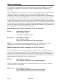
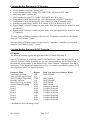
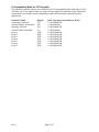
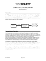
GPIB Interface, TE-0003, TE-1052
Instructions
Introduction
The GPIB communications is achieved through an ICS Electronics 4809A (internal) or 4899A
(external) GPIB-to-Modbus Interface Converter (henceforth referred to as “Converter”). GPIB
commands are converted to serial Modbus commands that are transmitted over RS-232. The
Converter take care of calculating block checksums that are required for communications to and
from the Series F4, F4T, or EZ-Zone Controller.
Controller
RS-232
ICS 4809A/4899A
GPIB to Modbus
Converter
Customer Supplied
GPIB Cable
Communications Parameters
The Converters are set at the factory for 9600 baud. The chamber’s Controller must also be
configured for 9600 baud. All chambers currently ship configured for 9600 baud. If you need to
change the setting on an older 1000 Series, models 105A and 115 chambers manufactured before
June 2003, this is located in the F4 Temperature Controller’s Main Page\Go to
Setup\Communications. If you are unable to enter this menu or change the setting from 19200,
then this menu has been locked. If a password is required, call TestEquity. See the “Series F4
User’s Manual” for instructions on how to clear the lock and navigate through the menus.
It is important to remember that GPIB interface messages communicate directly with the
Converters as the talk-listen addressed device. The Controller is NOT the GPIB device. Interface
messages that arrive at the Converter can be interpreted and used locally by the Converter, or
interpreted and re-transmitted to the Controller.
Data returning from the Controller is received by the Converter which then examines the block
checksum characters, strips them off, and re-transmits the desired data to the GPIB interface for
use by the controller.
Rev. 082815
Page 1 of 7
Modbus Communication
The Temperature Controller relies on a communication protocol called Modbus, which offers
multidrop serial capability for serial devices, reliable communication, and standardized
commands.
Since Modbus allows more than one device to share communications ports, each device requires
a Modbus address. The C command of the Converter sets the Modbus address of the
Temperature Controller. From that point, the Converter will use that address to communicate to
the Temperature Controller. Each Modbus device has its own characteristics and data items that
are examined and/or set. Data for the device is organized into registers. Register data is set by
sending a Write command to a specific register, and is examined by sending a Read command to
a register. The commands to read and write data in registers are performed by commands sent to
the Converter. These commands do resemble the final command that the Temperature Controller
sees, but the Converter also generates and sends a block checksum based on all the characters of
each message and sends it to the Temperature Controller.
Modbus Register Read / Write Commands for the F4 Controller:
R? reg, n
Read register command
Reg = Modbus register
n = number of registers to send
W reg, data
Write register command
Reg = Modbus register
Data = ASCII data written as 16-bit decimal value
NOTE: The '?' is optional and is included so programs like ICS’s GPIB Keyboard control
programs can automatically read back and display the response from a query.
Modbus Register Read / Write Commands for the F4T Controller:
The F4T Controller uses two consecutive register to control a value or to read back a process
variable. The two registers hold an IEEE-754 32-bit floating point word. The registers are read
and written to in the low word-upper word order. The RF? query reads a 32-bit floating point
value from two sequential register in low word-upper word order. The RF? does not require the
number of register to read since it is fixed at two registers.
RF? reg
Read register command
Reg = Modbus register plus next consecutive register
The WF command writes the num value in floating point format to two consecutive registers
starting with the low word register.
WF reg, data
Rev. 3
Write register command
Reg = Modbus register plus next consecutive register
Data = ASCII data written as a direct numerical value
Page 2 of 7
Common Modbus Registers for F4 Controller
•
•
•
•
•
•
•
•
•
Actual chamber temperature reading: 100.
Actual chamber humidity reading: 104. (Model 123H, 1007H and 1207C only)
Static temperature set point: 300.
Static humidity set point: 319. (Model 123H, 1007H and 1207C only)
Temperature set point during a profile: 4122. (Except model 105 with 97 controller)
Temperature set point during a profile: 5009. (Model 105 with 97 controller only)
Humidity set point during a profile: 4123. (Model 123H, 1007H and 1207C only)
Digital Output 1 (Event 1) in static set point mode: 2000. (Not applicable for model 105 with
97 controller)
Digital Output 2 (Event 2) in static set point mode: 2010. (Not applicable for model 105 with
97 controller)
The entire listing of Modbus registers for the Series F4 Temperature Controller are found in the
Series F4 User’s Manual, Chapter 7.
The entire listing of Modbus registers for the Series 96 Temperature Controller are found in the
Series 96 User’s Manual, pages 7.7 and A.3.
Common Modbus Registers for F4T Controller
F4T Mode
The following common registers are applicable in the F4T Mode (Data Map 1).
Some F4T parameters are contained within 32 bits (IEEE Float). Notice that only one (low order)
of the two registers is listed. By default, the low order word contains the two low bytes of the 32bit parameter. As an example, in the table below see Actual Chamber Temperature. Note that it
lists register 27586. Because this parameter is a float, it is actually represented by registers 27586
(low order bytes) and 27587 (high order bytes).
Parameter Name
Temperature Set Point
Temp Closed Loop Set Point*
Actual Chamber Temperature
Humidity Set Point
Hum Closed Loop Set Point*
Actual Chamber Humidity
Event 1
Event 2
Event 3
Event 4
Event 5
Event 6
Event 7
Register
2782
2810
27586
2942
2970
28906
16594
16596
16598
16600
16822
16824
16826
Data Type and Access (Read or Write)
IEEE Float RW
IEEE Float R
IEEE Float RW
IEEE Float R
IEEE Float R
Unsigned 16-bit RW
Unsigned 16-bit RW
Unsigned 16-bit RW
Unsigned 16-bit RW
Unsigned 16-bit RW
Unsigned 16-bit RW
Unsigned 16-bit RW
* Instantaneous Set Point during a ramp
Rev. 082815
Page 3 of 7
F4 Compatibility Mode for F4T Controller
The following common registers are available in the F4 Compatibility Mode (Data Map 2). This
will allow you to use software that was written for the original F4 Controller. Only a limited set
of parameters are available in this compatibility mode, but it should be sufficient for most
applications.
Parameter Name
Temperature Set Point
Actual Chamber Temperature
Humidity Set Point
Actual Chamber Humidity
Event 1
Event 2
Event 3
Event 4
Event 5
Event 6
Event 7
Rev. 3
Register
300
100
300
319
2000
2010
2020
2030
2040
2050
2060
Data Type and Access (Read or Write)
16-bit Signed RW
16-bit Signed R
16-bit Signed RW
16-bit Signed R
16-bit Signed RW
16-bit Signed RW
16-bit Signed RW
16-bit Signed RW
16-bit Signed RW
16-bit Signed RW
16-bit Signed RW
Page 4 of 7
Programming Sequences
Communicating to the Temperature Controller with GPIB requires commands to be made in a
standardized sequence. The sequence described here is language-independent, meaning that
descriptions of all of the possible languages are not given. Instead, given GPIB commands are
shown as strings, with an example language given to show program flow.
!
Samp_488
STRING
<lf>
<cr>
language
Comments are indicated with exclamation point
Command to GPIB interface card
Strings sent to GPIB device at specified address
Individual linefeed character
Individual carriage return character
Sample language element
Reset & Initialization Example for F4 Controller
This sequence should be performed once before establishing communications to the Temperature
Controller.
Command: IFC
! Reset GPIB interface card
Command: *RST <lf>
! Send reset command to ICS 4899A
Command: D 300<lf>
! Set ICS 4899A timeout to 300 ms
Reading Chamber Temperature Example for F4 Controller
The Temperature Controller sends data over the Modbus interface with an implied decimal point.
It is left to the user to remember this, and to scale the data accordingly. The Temperature
Controller has been configured by TestEquity to display one decimal point in the temperature
reading. If the configuration should change, then the program would not report the correct
temperature reading. To remedy this problem, always read the number of decimal points used by
Analog Input 1 before running the program.
Command: R? 606,1<lf>
Response: iData <lf>
! Send read command to register 606
! Returned variable iData represents ASCII
! numeric characters that are converted in this
! example to integer.
! 0 = no decimal point
! 1 = one decimal point
Command: R? 100,1<lf>
Response: fTemp <lf>
! Send read command to register 100
! Read the value of register 100. fTemp
! represents ASCII numeric characters,
! converted to float type.
if iData = 1 then
! Check iData
fTemp = fTemp / 10 ! 1=means that data has decimal and
endif
! we need to divide by ten.
print “Chamber Temp is”, fTemp
Rev. 082815
Page 5 of 7
Set Chamber Setpoint Examples for F4 Controller
Command: W 300, 230 <lf>
! Send write command to register 300 and
! change the setpoint to 23.0 degrees.
Command: W 300, 1005 <lf>
! Send write command to register 300 and
! change the setpoint to 100.5 degrees.
Command: W 300, -255 <lf>
! Send write command to register 300 and
! change the setpoint to -25.5 degrees.
F4T Controller Examples (Data Map 1)
Temperature and Humidity Set Points and Readings
Write Temperature Set Point
Write Humidity Set Point
WF 2782, value
WF 2942, value
Read Chamber Temperature
Read Chamber Humidity
RF? 27586
RF? 28906
Event Outputs (Chamber Functions and uncommitted outputs, 7 total)
Turn (Event 1) ON
Turn (Event 1) OFF
W 16594, 63 Event 1 is “Power”
W 16594, 62
Turn (Event 2) ON
Turn (Event 2) OFF
W 16596, 63 Event 2 is “Humidity” in Humidity models
W 16596, 62 Event 2 is “Purge” in Temp-only models
Event 2 is “LN2” in Model 3007C
The same syntax applies to events 3 through 7
Event 3 = 16598
Event 4 = 16598
Event 5 = 16600
Event 6 = 16602
Event 7 = 16604
Manual Ramp Parameters (Ramp to Set Point without a profile)
Ramp Action (Temperature)
W 2794, ## (where ## is one of the four numerical
choices below)
Off = 62
Startup = 88
Set Point = 85
Both = 13
Ramp Scale (Temp. °/Minutes)
Ramp Scale (Temp. °/Hours)
W 2796, 57
W 2796, 39
Ramp Rate (Temperature)
WF 2798, value (0 to 99,999)
Rev. 3
Page 6 of 7
Additional Resources
The ICS GPIB Modbus Interface manual provides detailed information on the Interface
Converter. Additional resources and LabVIEW drivers can be downloaded from
http://www.testequity.com/GPIB.
IMPORTANT NOTE: The examples shown in documentation from ICS are for illustration
purposes only. They do not represent the correct setup or configuration for TestEquity chambers.
Sample programs from ICS may change critical setup parameters, resulting in improper chamber
operation. They are provided as a guideline for how to write your own programs only. Correct
setup parameters are documented in the TestEquity chamber manuals.
ICS Manual Errata
To reflect the standard decimal point configuration of 0.0° in TestEquity chambers, the ICS
Electronics manual, Page 3-24, should be corrected as follows:
3.8.4
Writing to the Modbus Device
The nature of the command depends upon the specific Modbus
device. Simple writes are handled with the W command. In the
following example, a value of 50.0° is written to register 300.
i.e.
W 300,500
‘sets temperature setpoint
C7; W 300,500
‘concatenated command
Writes to multiple registers are possible with the WB command.
Rev. 082815
Page 7 of 7