1
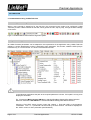
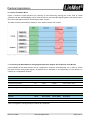
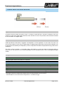
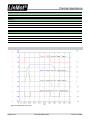
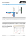
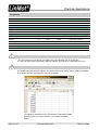
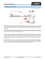
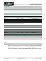
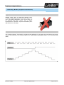
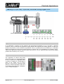
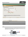
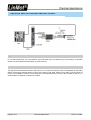
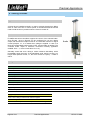
Practical Applications
Serie E1100 & B1100 Controller
Version: 0.2.7 (eng) fj, 10/09/2009
Status: Final
Practical Applications
© 2009 NTI AG
This work is protected by copyright.
Under the copyright laws, this publication may not be reproduced or transmitted in any form, electronic or
mechanical, including photocopying, recording, microfilm, storing in an information retrieval system, not even for
didactical use, or translating, in whole or in part, without the prior written consent of NTI AG.
LinMot® is a registered trademark of NTI AG.
Note
The information in this documentation reflects the stage of development at the time of press and is therefore
without obligation.
NTI AG reserves itself the right to make changes at any time and without notice to reflect further technical
advance or product improvement.
NTI AG
LinMot®
Haerdlistrasse 15
CH-8957 Spreitenbach
Page 2 of 47
Tel.: +41 (0)56 419 91 91
Fax: +41 (0)56 419 91 92
Email: [email protected]
Homepage: www.LinMot.com
Practical Applications
NTI AG / LinMot
Practical Applications
Table Of Contents
Table Of Contents................................................................................................................................................3
Use Of This Document ........................................................................................................................................3
Recommended Documentation...........................................................................................................................3
Introduction..........................................................................................................................................................4
a. Parametrization using LinMot Talk1100........................................................................................................4
b. Control and Status Word...............................................................................................................................5
c. Controlling the State Machine using Digital Inputs and Outputs on X4 (E1100) / X14 (B1100).....................5
1. Pusher With Two End Positions.......................................................................................................................7
2. Positioning Using Motion Profiles.....................................................................................................................9
3. Analog Position Mode ...................................................................................................................................11
4. Indexing Mode (Step/Direction/Zero) ............................................................................................................13
5. Moving To Any Desired End Positions, Using Serial Interfaces Or Fieldbusses ...........................................15
6. Moving To 8 (E1100) / 5 (B1100) Positions Using Via Digital I/O's................................................................20
7. Sequence Control..........................................................................................................................................22
8. High-Precision Positioning.............................................................................................................................24
9. Operation With An External Absolute Sensor................................................................................................26
10. Setting A Brake............................................................................................................................................28
11. Safe Pulse Inhibitor......................................................................................................................................30
12. Parallel Operation Of Two Motors (Master / Gantry)....................................................................................31
13. Force Doubling (Master / Booster)...............................................................................................................33
14. Evaluation Of End Positions And Reference Switches................................................................................35
15. Press With A Defined Force.........................................................................................................................37
16. Force Control With 0.1 N Resolution............................................................................................................39
17. Integration Of Rotary Motors .......................................................................................................................41
18. Synchronization To A Master Shaft: Master Encoder 0° to 360°..................................................................42
19. Synchronization To A Master Shaft: CAM1/CAM2.......................................................................................44
Contact .............................................................................................................................................................47
Use Of This Document
This document is an introduction to the different functionality of the LinMot E1100 and B1100 series controllers
which are shown in several practical applications.
Controller:
E1100 & B1100
Classification:
Training
Recommended Documentation
The user manuals are included in LinMot-Talk1100 or can be downloaded on www.linmot.com in the category
„Download -> Software & Manuals -> E1100/B1100 Controllers“.
The most important and recommended documents regarding the examples in this documents are shown below:
-
LinMot-Talk1100
Motion Control Software
Installation guide E1100 servo controllers
Installation guide B1100 servo controllers
Master Slave Application
EasySteps Application
TF Force Control
EC-Motors with E1100/B1100
NTI AG / LinMot
Practical Applications
Page 3 of 47
Practical Applications
Introduction
a. Parametrization Using LinMot-Talk1100
Motor Configuration Using The Motor Wizard
When a new controller is started up for the first time, the connected motor needs to be configured. LinMot
Talk1100 provides a Motor Wizard for this task, which guides the user, step by step, through the basic settings
of the motor.
Figure 1: The Motor Wizard is started with the magic wand symbol
Configuration Of Application Parameters
All LinMot firmware parameters can be adapted to the requirements of the application using LinMot Talk1100
software. A unique identification number is assigned to each parameter. This number, called the UPID (Unique
Parameter ID), is a 16-bit number. It is shown in hexadecimal format.
Figure 2: UPID Display in LinMot-Talk1100
Note
In the following applications the path to the required paramters is shown. If this path is to long to be
displayed it is shorten.
E.g. \Parameters\Motion Control SW\Motion Interface\RunMode Settings\Run Mode Selection
becomes \Parameters\MC SW\Motion Interface\RunMode Settings\Run Mode Selection
Using the “Find UPID” search function (menu bar “Search -> Find with UPID” or the keystroke
combination “Ctrl + U”, a parameter can be found by its UPID number. The UPID is displayed in
the “UPID” column for each parameter (see illustration).
Page 4 of 47
Practical Applications
NTI AG / LinMot
Practical Applications
b. Control And Status Word
Figure 3 shows the signal sequence for powering up and referencing (homing) the motor, both in normal
operation and after acknowledging a fault. It also shows the most important signals (state of the relevant bits in
the Control and Status Word) for controlling the state machine.
The state machine is described in chapter 3 of the “Motion Control SW” manual.
Figure 3: Signals for controlling the state machine
c. Controlling The State Machine Using Digital Inputs And Outputs On X4 (E1100) / X14 (B1100)
Control signals for the state machine can be configured on connector X4 respectively X14, in order to control
the state machine using digital signals. All signals can be assigned to X4 respectively X14 as desired. An
example of a configuration is below.
Inputs
\Parameters\Motion Control SW\Controller Configuration\X*.* I/O Definitions
Function
Value
E1100 (UPID)
B1100 (UPID)
Description
Ctrl Word: Switch On (Input)
On
1036h
62E8h
Switch On on X4.3 / X14.14
Ctrl Word: Home (Input)
On
1037h
62E9h
Home onX4.4 / X14.2
Ctrl Word: Error Acknowledge (Input)
On
1038h
62EAh
Error Ack on X4.5 / X14.15
Table 1: Configuration of the digital inputs on X4 (E1100) / X14 (B1100)
Outputs
\Parameters\Motion Control SW\Controller Configuration\X*.* I/O Definitions
Function
Value
E1100 (UPID)
B1100 (UPID)
Description
Status Word: Homed (Output)
On
1039h
62EEh
Homed on X4.6 / X14.17
Status Word: Error (Output)
On
103Ah
62EFh
Error on X4.7 / X14.5
Table 2: Configuration of the digital outputs on X4 (E1100) / X14 (B1100)
NTI AG / LinMot
Practical Applications
Page 5 of 47
Practical Applications
Figure 4: X4 I/O Definitions, control signals configured on connector X4 (E1100)
Note
Safety Voltage Enable (SVE)
E1100 series controllers (except for E1100-GP) have the Safety Voltage Enable input on X4.12. In
order to run, +24V DC must be connected here. Otherwise, the PWM generator in the power
electronics is hardware-disabled.
Invert the I/O Logic
The logic (active high / active low) of the digital inputs and outputs is configured under “X4 I/O
Definitions (E1100: UPID 104Bh to 1053h) respectively „X14 I/O Logic Definitions“ (B1100: UPID
43B0h to 43B5h and 43B8h to 43BDh).
The error output can be configured such that it is high (+24V) during operation, and low (0V) in the
error state.
Page 6 of 47
Practical Applications
NTI AG / LinMot
Practical Applications
1. Pusher With Two End Positions
E1100 AND B1100
Application
A product must be moved from point A (Pos 1, 20.5mm) to point B (Pos 2, 80.4mm). Selection of the two
positions is made via a digital signal. When the motor reaches one of the two positions, this should be indicated
to the controllers via a digital output.
Solution
LinMot provides the Run Mode “Triggered VA Interpolator” for this application. In this mode, the motor can
move to two positions on the rising or falling edge of a digital trigger signal. Both velocity and acceleration can
be programmed as desired (VA Interpolator). The VA Interpolator calculates a trapezoidal velocity profile for the
stroke time.
The motor moves to Position 1 on the falling edge, and Position 2 on the rising edge of the trigger signal on
X4.6 / X14.15. If the drive is in one of the two positions, this is indicated on X4.5 / X14.17 (configure as digital
output).
Configuration
Hardware Interface
The trigger signal is wired to X4.6 (E1100) / X14.15 (B1100)
Function
Value
Configure RunMode
Triggered VA-Interpolator
E1100 (UPID)
B1100 (UPID)
Description
\Parameters\Motion Control SW\Motion Interface\RunMode Settings\Run Mode Selection
On
Trigger input *
1450h
62A8h
Run Mode Triggered VAI
\Parameters\Motion Control SW\Controller Configuration\X*.* I/O Definitions
Trigger (Input)
On
1039h
62EAh
Trigger on X4.6 / X14.15
Direct
On
170Ch
62D8h
Trigger Mode „Direct“
* The trigger mode (Direct, inhibited and/or delayed) and the according parameters can be found here:
\Parameters\Motion Control SW\Controller Configuration\X*.* I/O Definitions\Trigger
NTI AG / LinMot
Practical Applications
Page 7 of 47
Practical Applications
Output
\Parameters\Motion Control SW\Controller Configuration\X*.* I/O Definitions
Status Word: In Target Position
On
Position 1
1038h
62EEh
In Pos an X4.5 / X14.17
\Parameters\MC SW\Motion Interface\Run Mode Settings\Triggered VA-Interpolator\Trig Fall Config
Position
20.5mm
145Ah
F14Dh
Position 1
Max. Speed
0.2m/s
Acceleration
F14Ch
Maximum velocity
145Ch
F14Ah
Acceleration
2
145Dh
F14Bh
Deceleration
3m/s
Deceleration
Position 2
145Bh
2
3m/s
\Parameters\MC SW\Motion Interface\Run Mode Settings\Triggered VA-Interpolator\Trig Rise Config
Position
80.4mm
145Fh
F151h
Position 2
Max. Speed
0.4m/s
Acceleration
Deceleration
1460h
F150h
Maximum velocity
2
1461h
F14Eh
Acceleration
2
1462h
F14Fh
Deceleration
5m/s
5m/s
Oszilloscope
Figure 5: Oscilloscope of one cycle
Page 8 of 47
Practical Applications
NTI AG / LinMot
Practical Applications
2. Positioning Using Motion Profiles
E1100 AND B1100 *
Application
Contact lenses are packaged in a machine. In order to avoid spilling the liquid, it must be moved without jerking
(minimal jerk). The packaging must be positioned at its target point (100mm) without jerk, while the return to the
starting position (0mm) of the linear drive must be as fast as possible. The motion is initiated by a trigger signal
from a proximity switch.
Solution
The “Triggered Time Curve” Run Mode is provided for this application. The rising edge of the trigger input
invokes a motion profile that is stored in the controller. The motion profile can be executed after a delay
following the trigger signal (delayed). This makes it easier to coordinate the actuation of the proximity switch
and the start of the motion.
The desired motion profile is generated using
the curve service (LinMot-Talk1100 manual).
Select 1 as the ID of the generated curve, and
download it to the controller.
NTI AG / LinMot
Practical Applications
Page 9 of 47
Practical Applications
Configuration
Hardware Interface
The trigger signal is wired to X4.6 (E1100) / X14.15 (B1100)
Function
Value
Configure RunMode
E1100 (UPID)
B1100 (UPID)
Description
\Parameters\Motion Control SW\Motion Interface\RunMode Settings\Run Mode Selection
Triggered Time Curves
On
Trigger input
1450h
62A8h*
Run Mode Triggered T. Curves
\Parameters\Motion Control SW\Controller Configuration\X*.* I/O Definitions
Trigger (Input)
On
1039h
62EAh
Trigger on X4.6 / X14.15
Delayed
On
170Ch
62D8h
Trigger Mode „Delayed“
Rise Delay Time
50ms
170Fh
62DBh
Set delay time
Set motion profile
\Parameters\MC SW\Motion Interface\Run Mode Settings\Triggered Curves Settings
Rise Curve ID
1
1482h
62A4h*
Set ID of the curve
Note B1100 Controller
* The curve support on B1100-GP controllers has to be unlocked with an access key.
The key has to be ordered separately. Minimal software requirement is LinMotTalk1100 V3.11.
Note
The LinMot-Talk1100 software supports the import of CSV files (Excel). Motion profiles generated
in Excel can thus be imported to the controller (Figure 6).
Figure 6: The base values of a motion profile are listed in mm in Column A.
The CSV file can be imported in the Curve Service in LinMot Talk1100. When
generating a new curve, select “FromFile” in the “Setpoint Calculation
Wizard.”
Page 10 of 47
Practical Applications
NTI AG / LinMot
Practical Applications
3. Analog Position Mode
E1100 AND B1100
Application
A blade guided by a linear drive has to cut open bottles with irregular shapes. The blade is to track to the shape
of the bottle.
A distance sensor measures the distance to the surface of the bottle, and sends the target position to the linear
drive via an analog signal from 0V (meaning 20mm) to 10V (meaning 80mm). Using a second, digital signal,
the drive must be able to move to a waiting position (0mm).
Solution
Positioning using an analog input signal is supported by the “Analog” Run Mode. The linear motor is positioned
between two freely configurable 0V and 10V positions, “proportional” to the input voltage on X4.4 (E1100) /
X14.20 (B1100).
The “Going To Position” function moves the drive to a waiting position. A digital signal is connected to X4.3
(E1100) / X14.14 (B1100) for this purpose. If the controller recognizes a high signal on this input, it changes to
State 15: Going To Position, and moves the drive to the configured position. If a low signal is present at this
input, the controller is in State 8: Operation Enabled, and follows the analog input signal.
NTI AG / LinMot
Practical Applications
Page 11 of 47
Practical Applications
Configuration
Hardware Interface
The analog signal is connected to X4.4 (E1100) / X14.20 (B1100)
The digital signal is connected to X4.3 (E1100) / X14.14 (B1100)
Function
Value
Configure RunMode
Analog
E1100 (UPID)
B1100 (UPID)
Description
\Parameters\Motion Control SW\Motion Interface\RunMode Settings\Run Mode Selection
On
1450h
Analog Input
62A8h
Run Mode Analog
\Parameters\Motion Control SW\Controller Configuration\X*.* I/O Definitions
Analog
On
1037h
*-
X4.4 as analog input
Position
On
1790h
62B2h
Signal type „Position“
0V Position
20mm
14D2h
F156h
0V Position
10V Position
80mm
14D3h
F157h
10V Position
* Not needed as the B1100 controller has a fix analog input on X14.20
Digital Input
\Parameters\Motion Control SW\Controller Configuration\X*.* I/O Definitions
Ctrl Word: Go To Position
On
1036h
Predef VA-Interpolator (Dynamics Analog Mode)
Max. Speed
1m/s
Acceleration
X4.3 / X14.14
\Parameters\Motion Control SW\Motion Interface\Predef VA Interpolator
14BEh
F0C4h
Maximum velocity
2
14BFh
F0C5h
Acceleration
2
14C0h
F0C6h
Deceleration
4m/s
Deceleration
62E8h
4m/s
Position and Dynamics of Wait Position (Go To Position)
\Parameters\Motion Control SW\State Machine Setup\Go To Position
Position
0mm
1725h
F146h
Wait position
Max. Speed
0.1m/s
Acceleration
1726h
F147h
Maximum velocity
2
1727h
F148h
Acceleration
2
1728h
F149h
Deceleration
1m/s
Deceleration
1m/s
Note
If the signal at X4.3 / X14.14 is high (24V), the linear motor moves to the 0mm position (waiting
position). If no voltage is present at X4.3 / X14.14, the drive follows the analog signal at X4.4.The
settings for the predefined VA Interpolator are used for analog positioning.
An overview and description of the various states can be found in the “Motion Control SW” manual.
Page 12 of 47
Practical Applications
NTI AG / LinMot
Practical Applications
4. Indexing Mode (Step/Direction/Zero)
E1100 AND B1100
Application
Stepper motors with an overarching stepper motor
controller (Step/Direction/Zero) have been used up to
now in an existing application. They are now going to
be replaced with linear motors, due to higher
requirements for dynamics and process reliability. The
step distance is 0.1µm/step.
Solution
The “Position Indexing” Run Mode is provided for this application. In this mode, the motor follows the counter
value of the indexer input. The indexer signal can be STEP/DIRECTION/ZERO (SDZ) or an incremental signal
(ABZ).
NTI AG / LinMot
Practical Applications
Page 13 of 47
Practical Applications
Configuration
Hardware Interface
Connect the indexing signal to X12 (E1100) / X14 (B1100)
Function
Value
Configure RunMode
Position Indexing
E1100 (UPID)
B1100 (UPID)
Description
\Parameters\Motion Control SW\Motion Interface\RunMode Settings\Run Mode Selection
On
1450h
Define Encoder Source (B1100)
62A8h
Run Mode Position Indexing
\Parameters\Motion Control SW\Controller Configuration\Indexing Encoder
Diff Encoder Input X14
On
-
62D6h
Indexing-signals connection
Step Dir (SD)
On
-
62CFh
Encoder type
1x
On
-
62D7
1x Decoding
Define Encoder Source (E1100)
\Parameters\Motion Control SW\Controller Configuration\Master Encoder
Ext Sensor Input X12
On
17A2h
-
Indexing-signals connection
Step Dir Zero (SDZ)
On
128Eh
-
Encoder type
1x
On
128Fh
-
1x Decoding
Position Step per Indexer Increment
Resolution
\Parameters\MC SW\Motion Interface\RunMode Settings\Pos Indexing Settings
0.1um
Limit Dynamics
Max. Speed
Acceleration
Deceleration
Page 14 of 47
14DDh
715Ch
Step distance
\Parameters\Motion Control SW\Motion Interface\Predef VA Interpolator
1m/s
14BEh
F0C4h
Maximum velocity
2
14BFh
F0C5h
Acceleration
2
14C0h
F0C6h
Deceleration
5m/s
5m/s
Practical Applications
NTI AG / LinMot
Practical Applications
5. Moving To Any Desired End Positions, Using Serial Interfaces Or
Fieldbusses
E1100 AND B1100
Application
The end positions of the linear drive must be freely programmable by the operator at the panel. In this example,
he wants to move from the starting position (0mm) to 20mm (v=1m/s, a=10m/s 2), then to 80mm (0.2m/s, 1m/s2),
then back to 0mm (2.5m/s, 30m/s2). The panel is connected to a PLC, which communicates with the LinMot
controller via a serial interface or fieldbus.
Solution
LinMot controllers can be connected to a superior control system via various interfaces, such as Ethernet,
Profibus DP, CANOpen, DeviceNet, LinRS Protocol (RS232 and RS485). The desired end positions can be set
directly by the controller.
The following resources are needed for communication with the controller.
Control Word: The state machine in the controller is controlled by the Control Word (Table 3). Among other
things, the controller is started and initialized using the Control Word, errors are
acknowledged, a QuickStop is initiated, etc.
Status Word:
Information about the controller is shown in the Status Word (Table 3). Whether the drive is
initialized, or an error or warning is active, or the drive is at the target position, etc.
StateVar:
The StateVar (Table 5) shows the state of the controller (Operation Enabled: 8, Homing: 9,
Error: 4 etc.). In State 4 (Error), the error code is shown in the 8 least significant bits. In State 8
(Operation Enabled), the 4 least significant bits show the Command Count. The StateVar is
needed for synchronization of motion commands via fieldbusses.
MC Interface:
Over the motion command interface (Table 4) all available motion commands can be sent to
the controller. In this example a „VAI Go To Position“-command with the parameters target
position, maximum velocity, acceleration an deceleration.
NTI AG / LinMot
Practical Applications
Page 15 of 47
Practical Applications
Control Word
Status Word
Bit
Name
Bit
Name
0
Switch On
0
Operation Enabled
1
Voltage Enable
1
Switch On Active
2
/Quick Stop
2
Enable Operation
3
Enable Operation
3
Error
4
/Abort
4
Voltage Enable
5
/Freeze
5
/Quick Stop
6
Go To Position
6
Switch On Locked
7
Error Acknowledge
7
Warning
8
Jog Move +
8
Event Handler Active
9
Jog Move -
9
Special Motion Active
10
Special Mode
10
In Target Position
11
Home
11
Homed
12
Clearance Check
12
Fatal Error
13
Go To Initial Position
13
Motion Active
14
Reserved
14
Range Indicator 1
15
Phase Search
15
Range Indicator 2
Table 3: Control and Status Word
MC Interface: „VAI Go To Position (010xh)“ Befehl
Name
Byte Offset
Description
Data Type
Unit
Header
0
010xh: VAI Go To Pos
UInt16
-
1.Par
2
Target Position
SInt32
0.1 um
2.Par
6
Maximal Velocity
UInt32
10-6 m/s
3.Par
10
Acceleration
UInt32
10-5 m/s2
4.Par
14
Deceleration
UInt32
10-5 m/s2
Table 4: Motion Command Interface (Here with VAI Go To Position command)
Page 16 of 47
Practical Applications
NTI AG / LinMot
Practical Applications
StateVar
Main State
15
14
13
12
11
Sub State
10
9
8
7
6
5
4
3
00: Not Ready To Switch On
0
01: Switch On Disabled
0
02: Ready To Switch On
0
03: Setup Error
Error Code which will be logged
04: Error
Logged Error Code
05: HW Tests
0 (Not yet defined)
06: Ready To Operate
0 (Not yet defined)
2
1
0
07: 08: Operation Enabled
Bits 0..3: Motion Command Count
Bit 4: Event Handler Active
Bit 5: Motion Active
Bit 6: In Target Position
Bit 7: Homed
09: Homing
0Fh: Homing Finished
10: Clearance Check
0Fh: Clearance Check Finished
11: Going To Initial Position
0Fh: Going To Initial Position Finished
12: Aborting
Not yet defined
13: Freezing
Not yet defined
14: Quick Stop Behaviour
Not yet defined
15: Going To Position
0Fh: Going To Position Finished
16: Jogging +
01h: Moving positive
0Fh: Jogging + Finished
17: Jogging -
01h: Moving negative
0Fh: Jogging – Finished
18: Linearizing
Not yet defined
19: Phase Search
Not yet defined
20: Special Mode
Not yet defined
Table 5: StateVar
NTI AG / LinMot
Practical Applications
Page 17 of 47
Practical Applications
Procedure
Before a command is sent, a check must be made that the controller is in State 8 (Operation Enabled) (high
byte of StateVar = 08h) and has been referenced (Homed: Bit 11 of the Status Word, or Bit 7 of StateVar).
Also, it must be noted that the controller executes a command only if the Command Count of the Command
Header (4 least significant bits) is not equal to the Command Count in StateVar (4 least significant bits). In the
simplest case, bit 0 in the Command Header is set to 0 or 1 alternately from command to command (toggled).
Example:
1. Operation Enabled? (High byte of the StateVar = 08h)
2. Motor referenced? (Bit 11 of the Status Word or Bit 7 of the StateVar is set)
3. Send position command 1 (Command Header = 0101h, Command Count = 1)
4. Motor in Position? (Bit 10 of the Status Word or Bit 6 of the StateVar is set)
5. Send position command 2 (Command Header = 0100h, Command Count = 0)
6. Motor in Position? (Bit 10 of the Status Word or Bit 6 of the StateVar is set)
On the application:
The following shows how to move to the positions from the application in order, and
what must be checked before and after sending a command.
1. Check
Is the controller in state 8? (High byte of StateVar = 08h)
Is the motor referenced? (Bit 11 of the Status Word or Bit 7 of StateVar is set)
2. Send motion command to 20mm with v = 1m/s and a=10m/s2. Set 1h as Command Count in the header
Word
Description
Example (values hexadecimal)
Unit
0
Command Header with ID
0101h
VAI Go To Position, 1 = Command Count
-
1-2
1. Command Parameter
00030D40h
Position, 50mm
0.1 um
3-4
2 Command Parameter
000F4240h
Maximum velocity, 1m/s
10-6 m/s
2
10-5 m/s2
10-5 m/s2
5-6
3. Command Parameter
000F4240h
Acceleration, 10m/s
7-8
4. Command Parameter
000F4240h
Deceleration, 10m/s2
3. Check
Has the command been completed by the controller? Bit 0-3 of StateVar (Command Count) = 1h
Is the motor at the target position? Bit 10 of the Status Word or Bit 6 in low byte of the StateVar is set
Is the controller in state 8? (High byte of StateVar = 08h) or is there an error? (High byte of StateVar = 04h or Bit 3 of
the Status Word is set)
4. Send motion command to 80mm with v = 0.2m/s and a=1m/s2. Set 2h as Command Count in the header
Word
Description
Example (values hexadecimal)
Unit
0
Command Header with ID
0102h
VAI Go To Position, 2 = Command Count
-
1-2
1. Command Parameter
000C3500h
Position, 80mm
0.1 um
3-4
2 Command Parameter
00030D40h
Maximum velocity, 0.2m/s
10-6 m/s
5-6
3. Command Parameter
000186A0h
Acceleration, 1m/s2
10-5 m/s2
7-8
4. Command Parameter
000186A0h
Deceleration, 1m/s2
10-5 m/s2
Page 18 of 47
Practical Applications
NTI AG / LinMot
Practical Applications
5. Check
Has the command been completed by the controller? Bit 0-3 of StateVar (Command Count) = 2h
Is the motor at the target position? Bit 10 of the Status Word or Bit 6 in low byte of the StateVar is set
Is the controller in state 8? (High byte of StateVar = 08h) or is there an error? (High byte of StateVar = 04h or Bit 3 of
the Status Word is set)
6. Send motion command to 0mm with v = 2.5m/s and a=30m/s2. Set 3h as Command Count in the header
Word
Description
Example (values hexadecimal)
Unit
0
Command Header with ID
0103h
VAI Go To Position, 3 = Command Count
-
1-2
1. Command Parameter
00000000h
Position, 0mm
0.1 um
3-4
2 Command Parameter
002625A0h
Maximum velocity, 2.5m/s
10-6 m/s
2
10-5 m/s2
10-5 m/s2
5-6
3. Command Parameter
002DC6C0h
Acceleration, 30m/s
7-8
4. Command Parameter
002DC6C0h
Deceleration, 30m/s2
6. Check
Has the command been completed by the controller? Bit 0-3 of StateVar (Command Count) = 3h
Is the motor at the target position? Bit 10 of the Status Word or Bit 6 in low byte of the StateVar is set
Is the controller in state 8? (High byte of StateVar = 08h) or is there an error? (High byte of StateVar = 04h or Bit 3 of
the Status Word is set)
NTI AG / LinMot
Practical Applications
Page 19 of 47
Practical Applications
6. Moving To 8 (E1100) / 5 (B1100) Positions Using Digital I/O's
E1100 AND B1100
Application
In an application, a product is to be sorted by size and placed accordingly in up to 7 (E1100) / 4 (B1100)
positions. The PLC used has only digital I/Os. Eight positions are required. One starting position, at which the
products are picked up, and 7 positions for placement. The 8 / 5 positions are to be invoked by 8 / 5 individual
digital input signals. As soon as the required position is reached, this is to be indicated by an InPosition output.
Travel to the placement locations has to be more slow (0.2 m/s, 2 m/ s2), while the return travel to the starting
position has to be fast (1 m/s, 10 m/s2).
Solution
The application is solved using Easy
Steps. Easy Steps is a simple application
to use, in which one configurable travel
command is initiated for a rising edge at
each of the inputs X4.4 to X4.11
(E1100) / X14.2 to X14.4 (B1100). Easy
Steps is a software application and has to
be installed during firmware installation.
("File -> Install Firmware")
Page 20 of 47
Practical Applications
NTI AG / LinMot
Practical Applications
Configuration
Function
Value
E1100 (UPID)
In Position Output
Status Word: In Target Position (Output)
B1100 (UPID)
Description
\Parameters\Motion Control SW\Controller Configuration\X*.* I/O Definitions
On
1036h
Position 1, X4.4 (E1100) / X14.2 (B1100)
62EEh
X4.3 / X14.17 as InPosition
\Parameters\Easy Steps\IO Motions\Input X*.* Config
Goto Abs Position
On
3500h
6418h
Command on rising edge
Position
0mm
3510h
F208h
Position 1
Max. Speed
1m/s
Acceleration
Deceleration
3511h
F209h
Maximum velocity
10m/s
2
3512h
F20Ah
Acceleration
10m/s
2
3513h
F20Bh
Deceleration
Position 2, X4.5 (E1100) / X14.15 (B1100)
\Parameters\Easy Steps\IO Motions\Input X*.* Config
Goto Abs Position
On
3600h
6428h
Command on rising edge
Position
200mm
3610h
F210h
Position 2
Max. Speed
0.2m/s
Acceleration
3611h
F211h
Maximum velocity
2
3612h
F212h
Acceleration
2
3613h
F213h
Deceleration
2m/s
Deceleration
2m/s
Further positions
Same as X4.4 and X4.5 (E1100) / X14.2 and X14.15 (B1100)
Note B1100 Controller
The B1100 series controllers for each input a separate “In Target Position” output can be set. This
function is called “Linked Output Mode” and can be found in the Easy Steps parameter tree.
E.g. for input X14.2 the associated “Linked Output” is X14.5.
Path: \Parameters\Easy Steps\IO Motions\Input X14.* Config\X14.* Linked Output Mode
NTI AG / LinMot
Practical Applications
Page 21 of 47
Practical Applications
7. Sequence Control
E1100 AND B1100-GP*
Application
Foam rubber squares are tested in a
machine. A linear motor is to compress the
square with a force of 40 N. After 2 seconds
of press time, the square is measured to
see if it is within tolerance.
The entire sequence is to be started by a
trigger signal. If the square is in spec, this is
to be indicated at a digital output. The same
applies if it is defective.
As motor a PS01-37x240 is used.
This is done in the following sequence:
1.
Move linear motor to 40 mm position, with v = 3 m/s and a =
5 m/s2
2.
Reduce force to 40 N and press squares together at a
speed of 0.05 m/s
3.
Press for 2 seconds
4.
Check the tolerances:
If the linear motor is at a position that is greater than 65 mm
and less than 75mm, then the square is in spec; otherwise,
it is defective.
5.
Return to start position at 0mm mm, with v = 0.5 m/s and a =
5 m/s2
Solution
The Command Table is provided for this application. This allows programming of sequences, from the simplest
to complex, using various motion commands, conditions, branches, parameter access, …
The command table for the required sequence is created with the LinMot-Talk1100 software, and is loaded into
the controller. The trigger signal is wired to X4.6. If the square is in tolerance, then this is indicated at X4.8
(OK); if it is outside the tolerance, this is indicated at X4.7 (Defect).
In order to limit the linear motor force to 40 N, the maximum current has to be limited. The model PS01-37x240
motor has a force constant of 23.8 N/A, which leads to a current of 1.68 A for 40 N (40N / 23.8N/A).
The controller’s following error monitor must be deactivated, since the motor will not reach the target position
when pressing. This is deliberate in this application.
Note B1100-GP Controller
* The B1100-GP controller supports the command table too. But there are some limitations like less
usable commands and a limit of 31 command lines. The configuration of the B1100-GP controller is
not shown in this example but can be realized as on the E1100 series controllers.
More detailed descriptions of the usable commands as well as the command table can be found in
the user manual “Motion Control SW”.
Page 22 of 47
Practical Applications
NTI AG / LinMot
Practical Applications
Configuration
Hardware Interface
Trigger signal at X4.6 (Input)
Error signal at X4.7 (Output)
OK signal at X4.8 (Output)
Function
Value
Configure RunMode
E1100 (UPID)
Description
\Parameters\Motion Control SW\Motion Interface\RunMode Settings\Run Mode Selection
Command Table Mode
On
Command Table Entry ID
\Parameters\Motion Control SW\Motion Interface\RunMode Settings\Command Table Settings
Command Table Entry ID
1
Trigger Input
1450h
1485h
Run Mode Command Table Mode
Set command line start ID
\Parameters\Motion Control SW\Controller Configuration\X4 I/O Definitions
Trigger (Input)
On
1039h
X4.6 as Trigger
Direct
On
170Ch
Trigger Mode „Direct“
* The trigger mode (Direct, inhibited and/or delayed) and the according parameters can be found here:
\Parameters\Motion Control SW\Controller Configuration\X*.* I/O Definitions\Trigger
Error Output
Interface Output
\Parameters\Motion Control SW\Controller Configuration\X4 I/O Definitions
On
OK Output
Interface Output
103Ah
X4.7 as Interface Output
\Parameters\Motion Control SW\Controller Configuration\X4 I/O Definitions
On
Deactivating following error monitoring
103Bh
X4.8 as Interface Output
\Parameters\Motion Control SW\Errors & Warnings\Error Detection Mask
Position Lag Always
False
1587h
Turn off general following error
Position Lag Standing
False
1588h
Turn off following error at rest
Create Command Table
\Command Table
Finally save the command table on the controller -> „Download to Controller“
NTI AG / LinMot
Practical Applications
Page 23 of 47
Practical Applications
8. High-Precision Positioning
E1100 AND B1100
Application
For a high-precision positioning
application, the position of the linear
motor should be measured by an
external high-resolution sensor to
improve positioning accuracy.
Solution
E1100 / B1100 series controllers support the integration of an external position sensor at X12 (E1100) / X13
(B1100). In this example, an AB linear encoder, Model MS01-1/D (LinMot Item No. 0150-1840) with a
resolution of 1μm is used.
Configuration
Hardware Interface
Connect the external sensor to X12 / X13 (Check pin assignment –> Installation Guides)
Figure 7: X12 connector on E1100 controller
Page 24 of 47
Practical Applications
NTI AG / LinMot
Practical Applications
Sensor configuration
Motor Wizard > Schritt 4
Open the Motor Wizard -> Step 4, "External Position Sensor"
Type: The MS01-1/D is an AB Sensor
Count Direction: Positive or Negative
Resolution: 1um
Further settings are available under \Parameters\Motor Configuration\Position Feedback\Feedback on X*.*"
Note
After configuring the external sensor, the count direction should be checked as follows. First, start
the firmware, and then move the slider by hand. While doing this, observe the position in the
LinMot-Talk1100 control panel. When the slider is being pulled out of the stator, then the actual
position should count in the positive direction
NTI AG / LinMot
Practical Applications
Page 25 of 47
Practical Applications
9. Operation With An External Absolute Sensor
E1100 AND B1100
Application
In a complex application, it is not possible to move the linear motor for referencing. For this reason, an absolute
sensor is used to determine the position of the linear drive.
Solution
The signal from the absolute sensor is fed to the PLC. In order for the linear motor to compensate for boundary
effects, and achieve optimal position control, the location of the slider relative to the stator must be known at
the time of initialization. Since the current position of the absolute sensor is sent to the controller by the PLC, a
serial interface or fieldbus connection is needed.
Page 26 of 47
Practical Applications
NTI AG / LinMot
Practical Applications
Configuration
Function
Value
E1100 (UPID)
Set Homing Mode
B1100 (UPID)
Description
\Parameters\Motion Control SW\State Machine Setup\Homing
Actual Position
On
13C4h
61E8h
Homing-Mode “Actual Position”
Disable
On
13D8h
61F3h
Deactivate Auto on Homing
Sequence to initialize the drive
1.
Turn on controller
2.
Enable Motor
3.
PLC reads current position of the absolute sensor
4.
Write home position (current position of the absolute sensor) UPID 13C7h (E1100) / F0F5h (B1100)
5.
Write Slider Home Position (see below) UPID 13CAh (E1100) / F0F8h (B1100)
6.
Homing to Actual Position (set Bit 11 in the Control Word)
7.
As soon as Bit 11 (Homed) in the Status Word is set, erase Bit 11 in the Control Word again
8.
Drive is ready
Determining the Slider Home Position
In order to ensure correct initialization of the drive, it must first be determined how far the slider extends out of the stator
(= distance k) when the absolute sensor is at the zero position. (See illustration)
The Slider Home Position that must be written in Step 5 is the current position of the absolute sensor plus the distance k.
Note
If changes are made to the mechanics, then k may need to be determined again.
NTI AG / LinMot
Practical Applications
Page 27 of 47
Practical Applications
10. Setting A Brake
E1100 AND B1100
Application
A linear drive is installed vertically. In order to prevent the axis from falling
down in case of an error or loss of power, a mechanical brake should be
used to hold the axis in position when the motor is turned off.
Solution
E1100/B1100 series controllers support the control of an external brake.
X4.3 (E1100) / X14.17 (B1100) can be configured for use as a brake
output, with a maximum output current of 1A. The brake uses the no-signal
current principle. I.e., it is vented when voltage is applied. In case of a
fault, the inverted brake output goes to OFF, and the brake is applied. The
controller brake output is therefore connected inversely (operation
enabled: X4.3 = 1, motor current less: X4.3 = 0).
Generally errors that occur during a motion initiate a QuickStop, which
immediately stops the motor. If the QuickStop ends, then the motor is no
longer under position control; i.e., the motor current is 0 (zero) → brake is
active.
Configuration
Hardware Interface
Brake output to valve is connected on X4.3 (E1100) / X14.17 (B1100)
Function
Value
E1100 (UPID)
Brake Output
Brake (Ouput)
B1100 (UPID)
Description
\Parameters\Motion Control SW\Controller Configuration\X*.* I/O Definitions
On
Brake Mode
1036h
62EEh
Brake output on X4.3 / X14.17
\Parameters\Motion Control SW\Controller Configuration\X*.* I/O Definitions\Brake X*.*
Status Word: Operation Enabled
True
1717h
43D5h
Quick Stop
True
1716h
43D6h
Apply Delay Time
100ms
171Bh
6209h
Set as needed
Release Delay Time
50 ms
171Ch
620Ah
Set as needed
Apply Delay Time:
Motor cutoff is delayed until the brake has been applied.
Release Delay Time:
Brake release is delayed until the active position control is working.
Page 28 of 47
Practical Applications
NTI AG / LinMot
Practical Applications
Figure 8: Signal sequence in case of a QuickStop
Note
In order to be able to initiate a QuickStop externally (digital I/O, field bus), UPID 13EEh (E1100) /
4282h (B1100) must be set to "False."
NTI AG / LinMot
Practical Applications
Page 29 of 47
Practical Applications
11. Safe Pulse Inhibitor
ONLY
E1100
The safe pulse inhibitor (Safety Voltage Enable) is a safety function. The PWM generator in the power
electronics is hardware enabled only after the Safety Voltage Enable input (X4.12) is high (+24V).
The diagram below shows a wiring suggestion for implementing a Category 3 "safe stop" per EN954-1, with
controlled shutdown (Stop 1 per DIN EN60204-1).
The safety function SVE fulfills the following criteria of the new machine directive EN ISO 13849-1:
•
Category
cat = 3
•
Performance Level
PL = d
•
Diagnostic Coverage
DC = medium
•
Mean time to hazardous failure of one channel
MTTFd = 49.8 Years
As soon as the pulse enable is inhibited by the SVE signal, the final stage of the power supply is safely
switched off without any delay. The pulse enable is provided as an external terminal. The servo controller
divides it into two independent signals internally. The external wiring must be done in such a way as to prevent
shorting to other current-carrying components.
Figure 9: "Safe stop" wiring suggestion
Page 30 of 47
Practical Applications
NTI AG / LinMot
Practical Applications
12. Parallel Operation Of Tw o Motors (Master / Gantry)
ONLY
E1100
Application
A portal with two parallel X-axis is to be constructed. The two motors should move in parallel, and be able to be
controlled as a single axis by the overarching controller.
Solution
For this application, the LinMot controllers provide master slave application software with a "Master Gantry"
function. Two E1100 series controllers are connected to each other using connector X7/X8 or X10/X11 (E1100GP).
One controller is configured as the master, and is addressed by the overarching controller, and the other is
configured as a slave, and receives the required target position from the master. Both motor positions are
controlled independently of each other. The slave controller is initialized in parallel with the master.
In gantry operation, the motors are located a certain distance apart, and must therefore not be 100%
rigidly coupled!
NTI AG / LinMot
Practical Applications
Page 31 of 47
Practical Applications
Configuration
The motor must be configured on both controllers (Motor Wizard)
Installation of the master-slave application on both controllers: Install firmware and choose „Master Slave“ as application
Connect both controller via CAN Bus (connector X7/X8) with an Ethernet cable per EIA / TIA 568A (Item No. 0150-1853).
Set CAN-Term S3.3 to ON for both controllers.
Function
Value
E1100 (UPID)
Configuration Master
Description
\Parameters\Master Slave Application\
CAN
On
3EF7h
Select CAN as the interface
Gantry Master
On
30D4h
Configure controller as Gantry Master
Configuration Slave
\Parameters\Master Slave Application\
CAN
On
3EF7h
Select CAN as the interface
Gantry Slave
On
30D4h
Configure controller as Gantry Slave
Normal *
On
30E2h
Select the direction of the slave drive
* Normal = both stators are oriented in the same direction
Note
Instead of CAN also RS485 can be used as connection between master and slave
(set UPID 3EF7h to RS 485)
Additional information can be found in the user manual „Master Slave Application“.
Page 32 of 47
Practical Applications
NTI AG / LinMot
Practical Applications
13. Force Doubling (Master / Booster)
ONLY
E1100
Application
A tool is to be moved horizontally in an assembly fixture. In order to increase dynamics and force, two motors
are to be operated in parallel. The two motors should be able to be controlled as a single axis by the
overarching controller.
Solution
For this application, the LinMot controllers provide master-slave application software with a "Master Booster"
function. Two E1100 series controllers are connected to each other using connector X7/X8 or X10/X11 (E1100GP).
One controller is configured as the master, and is addressed by the overarching controller, and the other is
configured as a slave, and receives the calculated target current from the master (slave position is not
controlled). The slave controller is initialized in parallel with the master.
In booster operation, the motors must be rigidly coupled.
NTI AG / LinMot
Practical Applications
Page 33 of 47
Practical Applications
Configuration
The motor must be configured on both controllers (Motor Wizard)
Installation of the master-slave application on both controllers: Install firmware and choose „Master Slave“ as application
Connect both controller via CAN Bus (connector X7/X8) with an Ethernet cable per EIA / TIA 568A (Item No. 0150-1853).
Set CAN-Term S3.3 to ON for both controllers.
Function
Value
E1100 (UPID)
Configuration Master
Description
\Parameters\Master Slave Application\
CAN
On
3EF7h
Select CAN as the interface
Current Master
On
30D4h
Configure controller as Current Master
Configuration Slave
\Parameters\Master Slave Application\
CAN
On
3EF7h
Select CAN as the interface
Current Slave
On
30D4h
Configure controller as Current Slave
Normal *
On
30E2h
Select the direction of the slave drive
* Normal = both stators are oriented in the same direction
Note
Instead of CAN also RS485 can be used as connection between master and slave
(set UPID 3EF7h to RS 485)
Additional information can be found in the user manual „Master Slave Application“.
Page 34 of 47
Practical Applications
NTI AG / LinMot
Practical Applications
14. Evaluation Of End Positions And Reference Sw itches
E1100 AND B1100
Application
Two LinMot drives move independently on the same slider. In order to prevent collisions, an end position switch
(switch 2) is mounted on one stator. When this switch is activated, it means that the distance between the two
stators has become too close, and the motors must be immediately stopped. In addition, two additional end
switches are installed at the two end positions (switches 1 and 3).
Solution
End switches can be connected to the X4.8 and X4.9 (E1100) / 14.3 and 14.16 (B1100). If one of these end
switches is activated, then the motor is immediately stopped by a Quick Stop.
NTI AG / LinMot
Practical Applications
Page 35 of 47
Practical Applications
Configuration
Hardware Interface
Connect switch 1 to X4.8 / X14.3 on Controller 1
Connect switch 2 to X4.9 / X14.16 on Controller 1 and X4.8 / X14.3 on Controller 2
Connect switch 3 to X4.9 / X14.16 on Controller 2
Function
Value
E1100 (UPID)
Configuration Controller 1
B1100 (UPID)
Description
\Parameters\Motion Control SW\Controller Configuration\X*.* I/O Definitions
Limit Switch Negative (Input)
On
103Bh
62EBh
X4.8 / X14.3 as limit switch neg
Limit Switch Positive (Input)
On
103Ch
62ECh
X4.9 / X14.16 as limit switch pos
Quick Stop
On
121Bh
61D6h
Error behavior Quick Stop
Deceleration
10 m/s2
1721h
F144h
Deceleration for Quick Stop
Configuration Controller 2
\Parameters\Motion Control SW\Controller Configuration\X*.* I/O Definitions
Limit Switch Negative (Input)
On
103Bh
62EBh
X4.8 / X14.3 as limit switch neg
Limit Switch Positive (Input)
On
103Ch
62ECh
X4.9 / X14.16 as limit switch pos
Quick Stop
On
121Bh
61D6h
Error behavior Quick Stop
1721h
F144h
Deceleration for Quick Stop
Deceleration
2
10 m/s
Adapt the end switch logic, if needed (on both cont.)
\Parameters\Motion Control SW\Controller Configuration\X*.* I/O Definitions
Invert I/O X*.* (low active)
False/True
1050h
43B3h
Logic of X4.8 / X14.3
Invert I/O X*.* (low active)
False/True
1051h
43B4h
Logic of X4.9 / X14.16
Page 36 of 47
Practical Applications
NTI AG / LinMot
Practical Applications
15. Press With A Defined Force
E1100 AND B1100-GP*
Application
In an application, fasteners are inserted. In order to
check that the fastener is seated correctly, the end
position and the force applied are to be checked.
The required force is 22 N, and the end position is
52mm with a tolerance of +/- 1mm. If the end position
is reached, and the force has not been applied after
2s, or if the end position is outside of the tolerance,
then an error is to be signaled. Otherwise an OK is
signaled. The maximum speed during insertion must
not exceed 0.05 m/s.
The check is started by a trigger signal.
A PS01-23x160 motor is used.
Solution
An open loop force control is fundamentally very simple, and is done by limiting the maximum motor current.
The resulting force is calculated using the force constant [N/A]. In case of a motor of model PS01-23x160, the
force constant is 22.08 N/A. Therefore, a maximum current of 0.996 A must be set in order to press at 22 N.
Note that the maximum permissible current depends on the controller and the motor model used .
The trigger signal and the two digital outputs for the error and OK signals are wired to connector X4.
The required sequence can be realized quite easily using the command table.
Note B1100-GP Controller
* The B1100-GP controller supports the command table too. But there are some limitations like less
usable commands and a limit of 31 command lines. The configuration of the B1100-GP controller is
not shown in this example but can be realized as on the E1100 series controllers.
More detailed descriptions of the usable commands as well as the command table can be found in
the user manual “Motion Control SW”.
NTI AG / LinMot
Practical Applications
Page 37 of 47
Practical Applications
Configuration
Hardware Interface
Trigger signal at X4.6 (Input)
Error signal at X4.7 (Output)
OK signal at X4.8 (Output)
Function
Value
Configure RunMode
Description
\Parameters\Motion Control SW\Motion Interface\RunMode Settings\Run Mode Selection
Triggered Command Table
Rise Command Table Entry ID
E1100 (UPID)
On
1450h
Run Mode Triggered Command Table
\Parameters\Motion Control SW\Motion Interface\RunMode Settings\Triggered Command Table Settings
Rise Command Table Entry ID
1
Trigger Input
1486h
Set command line start ID
\Parameters\Motion Control SW\Controller Configuration\X4 I/O Definitions
Trigger (Input)
On
1039h
X4.6 as Trigger
Direct
On
170Ch
Trigger Mode „Direct“
* The trigger mode (Direct, inhibited and/or delayed) and the according parameters can be found here:
\Parameters\Motion Control SW\Controller Configuration\X*.* I/O Definitions\Trigger
Error Output
Interface Output
\Parameters\Motion Control SW\Controller Configuration\X4 I/O Definitions
On
OK Output
Interface Output
103Ah
X4.7 as Interface Output
\Parameters\Motion Control SW\Controller Configuration\X4 I/O Definitions
On
Deactivating following error monitoring
103Bh
X4.8 as Interface Output
\Parameters\Motion Control SW\Errors & Warnings\Error Detection Mask
Position Lag Always
False
1587h
Turn off general following error
Position Lag Standing
False
1588h
Turn off following error at rest
Create Command Table
\Command Table
Finally save the command table on the controller -> „Download to Controller“
Page 38 of 47
Practical Applications
NTI AG / LinMot
Practical Applications
16. Force Control With 0.1 N Resolution
E1100 AND B1100 *
Application
Springs are to be quality tested for force in an automated
system. A constant force of 43.2 N must be applied vertically
to the springs. Using the internal position measurement, it is
determined how far the spring is compressed. Depending on
the measured distance, the springs meet the specification.
The applied force is measured by a load cell with a
measurement range of 0 to 50 N.
Solution
LinMot provides a technology function with force regulation that allows a precise closed loop control of a
constant force across the entire stroke range, regardless of the current position, at a resolution of 0.1 N. Since
the force generated by the linear motor is measured by a load cell, and is controlled directly in the servo
controller, interference effects, such as differences in friction, dirt, slip-stick effects, temperature variations, and
other variables are compensated for. The force determined by the load cell is fed to connector X4.4 as an
analog signal (0 to 10V).
Configuration (For B1100-GP see note)
Hardware Interface
The analog signal from the load cell is connected to X4.4
Function
Value
Configuration of X4.4
E1100 (UPID)
Description
\Parameters\Motion Control SW\Controller Configuration\X4 I/O Definitions
Analog Input
On
1037h
X4.4 as analog input
Force
On
1790h
Force signal type
0V Force
0V Force
10V Force
10V Force
NTI AG / LinMot
\Parameters\Motion Control SW\Controller Configuration\X4 I/O Definitions\Analog In X4.4\Analog Force Feedback Config
0
1501h
Set force at 0V
\Parameters\Motion Control SW\Controller Configuration\X4 I/O Definitions\Analog In X4.4\Analog Force Feedback Config
50N
1502h
Practical Applications
Set force at 10V
Page 39 of 47
Practical Applications
The force control can now be used with the following commands
VAI Go To Pos With Higher Force Ctrl Limit (380xh)
Press command
Travel to a defined target position. As soon as the measured force reaches the force limit, the controller changes to force
control mode, with the target force = force limit. To move with position control again, use the command, "VAI Go To Pos
From Act Pos And Reset Force Control (381xh)".
VAI Go To Pos With Higher Force Ctrl Limit And Target Force (383xh)
Press command
Travel to a defined target position. As soon as the measured force reaches the force limit, the controller changes to force
control mode, with the target force = target force. To move with position control again, use the command, "VAI Go To Pos
From Act Pos And Reset Force Control (381xh)".
VAI Go To Pos With Lower Force Ctrl Limit (384xh)
Pull command from V3.11
Travel to a defined target position. As soon as the measured force reaches the force limit, the controller changes to force
control mode, with the target force = force limit. To move with position control again, use the command, "VAI Go To Pos
From Act Pos And Reset Force Control (381xh)".
VAI Go To Pos With Lower Force Ctrl Limit And Target Force (385xh)
Pull command from V3.11
Travel to a defined target position. As soon as the measured force reaches the force limit, the controller changes to force
control mode, with the target force = target force. To move with position control again, use the command, "VAI Go To Pos
From Act Pos And Reset Force Control (381xh)".
Force Ctrl Change Target Force (382xh)
Using this command, the target force can be changed in force control mode.
VAI Go To Pos From Act Pos And Reset Force Control (381xh)
Reactivates position control, and moves to the defined position.
Detailed descriptions of the commands are found in the Motion Control SW manual.
Note
Force control is a technology function that is ordered separately.
(LinMot Item No. 0150-2503)
Additional information can be found in the user manual “TF Force Control”.
* Note B1100
From LinMot-Talk1100 V3.11 the force control is supported by the B1100-GP Controller too.
The settings can be done here:
\Parameters\Motion Control SW\Protected Technology Functions\Analog Force Feedback Control
Page 40 of 47
Practical Applications
NTI AG / LinMot
Practical Applications
17. Integration Of Rotary Motors
E1100 AND B1100
Application
A brushless servomotor (EC motor) with a gearbox
and spindle are to be used with a LinMot Controller
E1130-DP in a profibus system.
The drive is a Faulhaber Motor, model 2036 U 036
B K1155.
The gearbox has a reducing ratio of 3.71:1.
The spindle has a pitch of 1.5mm per revolution.
Solution
E1100 series controllers support the control of 3-phase rotary EC motors. Actuator Definition Files (*.adf) are
available for some motor models.
All motors that are currently supported are listed in the user manual "EC_Motors_with_E1100".
Configuration
Connecting the Motor
Motor phases A, B, C to X2 (Alternatively X3)
A->U, B->V, C->W
Analog Hall-effect sensors A, B, C to X3
A->X3.4, B->X3.9, C->X3.5
Configuration of the Controller
Open the Motor Wizard
Select ADF file: ..\Other Motors\EC Motors\Faulhaber\Faulhaber_EC.adf
Select motor model: 2036 U 036 B K1155
At step 3 of the wizard, the reduction ratio between the motor angle and the position is set. If the controller is provided with
a position in mm, then the linear table on the spindle should move to this position.
Therefore, the number of millimeters of stroke for each revolution of the motor must be calculated. The nominal reduction
of the gearbox is 3.71:1; the pitch of the spindle is 1.5 mm per revolution.
Therefore, one revolution of the motor is 1.5/3.71 = 0.4043 mm. This value is entered at "1 revolution = … mm"
Make settings in steps 4 and 5, and close the Wizard.
Note
The same scope of functions that is available for linear motors is also available for controlling rotary
motors.
NTI AG / LinMot
Practical Applications
Page 41 of 47
Practical Applications
18. Synchronization To A Master Shaft: Master Encoder 0° to 360°
ONLY
E1100
Application
A linear motor is to execute a motion profile synchronously with a master shaft. The incremental Master
Encoder (ABZ) has 512 counts per revolution.
The entire motion profile is to be executed within one revolution of the master shaft (360 machine degrees).
Solution
This application is solved using the "CAM Mode" Run Mode. A motion profile can be created and stored in the
controller. The motion profile is started after the controller is started up, if the drive has been initialized, the
controller is in State 8 "Operation Enabled", and a Z-signal from the encoder is detected for the first time.
Configuration
Creating the motion profile
The encoder signal from the master shaft is evaluated 4 times. This results in 2048 increments per revolution of the master
encoder.
In the Curve Inspector in LinMot-Talk1100, the desired motion profile is created as a "CAM (Pos. vs. Enc. Pos.)", with a length of
2048 increments. Instructions for creating curves can be found in the user manual “LinMot-Talk1100”.
The created curve is then loaded into the controller, with ID 1.
Page 42 of 47
Practical Applications
NTI AG / LinMot
Practical Applications
Hardware Interface
The Master Encoder is connected to X12 of the controller.
Function
Value
Configure RunMode
E1100 (UPID)
Description
\Parameters\Motion Control SW\Motion Interface\RunMode Settings\Run Mode Selection
CAM Mode
On
1450h
Run Mode CAM
Start Counts
0
1523h
Set start offset in counts
Curve ID
1
1524h
Set ID of the curve to be used
Configure Master Encoder
\Parameters\Motion Control SW\Controller Configuration\Master Encoder
Ext Sensor Input X12
On
172Ah
Master Encoder to X12
ABZ
On
128Eh
Encoder type ABZ
4x
On
128Fh
Decode encoder signals 4 times
CAM Length
2048
1525h
Length of the CAM disc
NTI AG / LinMot
Practical Applications
Page 43 of 47
Practical Applications
19. Synchronization To A Master Shaft: CAM1/CAM2
ONLY
E1100
Application
In an application, the positions 0mm, 50mm, and 100mm are to be moved to, depending on the machine angle
(Position Master Encoder / master shaft). (See illustration above).
Solution
Series E1100 controllers support the definition of two CAMs. This allows loading of a motion profile into a CAM
while the motion profile of the other CAM is being run, and vice versa.
The Master Encoder has 512 counts per revolution. The controller is configured such that the encoder signal is
decoded 4 times, which results in 2048 increments per revolution.
Page 44 of 47
Practical Applications
NTI AG / LinMot
Practical Applications
Configuration
Creating the motion profile
A simple sinusoidal motion profile is needed at first. This is generated in LinMot-Talk1100, and saved to the controller.
Type: CAM (Pos. vs. Enc. Pos.), 0 to 100mm, length: 512 Counts, ID 1
Hardware Interface
The ABZ signal from the Master Encoder is connected to X12 of the controller.
Configure Master
Function
Value
Configure Master Encoder
E1100 (UPID)
Description
\Parameters\Motion Control SW\Controller Configuration\Master Encoder
Ext Sensor Input X12
On
172Ah
Master Encoder to X12
ABZ
On
128Eh
Encoder type ABZ
4x
On
128Fh
Decode encoder signals 4 times
CAM Length
2048
1525h
Length of the CAM disc
NTI AG / LinMot
Practical Applications
Page 45 of 47
Practical Applications
Sequence
1.
Load the curve into CAM1 using the following command
Encoder CAM 1 Define Curve To Pos In Counts (114xh)
2.
Curve ID
1
Curve Start Count
0 Incr
Target Position
50 mm
Curve Length
341 Incr
Activate CAM mode with command
Encoder CAM Enable (100xh)
Now as soon as the first Z-signal is detected from the encoder, the motor will follow the motion profile in CAM1.
3.
While the curve in CAM1 is being traveled, CAM2 must be loaded
Encoder CAM 2 Define Curve To Pos In Counts (124xh)
4.
Curve ID
1
Curve Start Count
512 Incr
Target Position
100 mm
Curve Length
341 Incr
While the curve in CAM2 is being traveled, CAM1 must be loaded again
Encoder CAM 1 Define Curve To Pos In Counts (114xh)
5.
Curve ID
1
Curve Start Count
1195 Incr
Target Position
50 mm
Curve Length
341 Incr
While the curve in CAM1 is being traveled, CAM2 must be loaded again
Encoder CAM 2 Define Curve To Pos In Counts (124xh)
6.
Curve ID
1
Curve Start Count
1536 Incr
Target Position
0 mm
Curve Length
512 Incr
While the curve in CAM2 is being traveled, CAM1 must be loaded again for the next revolution of the encoder
Encoder CAM 1 Define Curve To Pos In Counts (114xh)
7.
Curve ID
1
Curve Start Count
0 Incr
Target Position
50 mm
Curve Length
341 Incr
Repeat steps 3 bis 6
Note
Motion Commands can be initiated, on one hand, through serial interfaces, fieldbusses, or the
Command Table. For practice purposes, however, they can also be transmitted via the Control
Panel in LinMot Talk 1100 (Motion Command Interface). Further information can be found in the
user manuals "LinMot Talk1100" and "Motion Control SW".
Synchronization and starting up when the Master Encoder is stopped, or (re)synchronization to a
running Master Encoder, are described in the "Motion Control SW" user manual, in Chapter 5.3.
Page 46 of 47
Practical Applications
NTI AG / LinMot
Practical Applications
Contact
---------------------------------------------------------------------------------------------------------------------------------------------------SWITZERLAND
NTI AG
Haerdlistr. 15
CH-8957 Spreitenbach
Sales and Administration:
+41-(0)56-419 91 91
[email protected]
Tech. Support:
+41-(0)56-544 71 00
[email protected]
Tech. Support (Skype) :
skype:support.linmot
Fax:
Web:
+41-(0)56-419 91 92
http://www.linmot.com/
---------------------------------------------------------------------------------------------------------------------------------------------------USA
LinMot, Inc.
5750 Townline Road
Elkhorn, WI 53121
Sales and Administration:
877-546-3270
262-743-2555
Tech. Support:
877-804-0718
262-743-1284
Fax:
800-463-8708
262-723-6688
E-Mail:
Web:
[email protected]
http://www.linmot-usa.com/
---------------------------------------------------------------------------------------------------------------------------------------------------Please visit http://www.linmot.com/ to find the distribution near you.
Smart solutions are…
NTI AG / LinMot
Practical Applications
Page 47 of 47