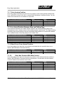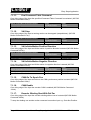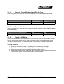
1
Documentation of the EasySteps Application of the following Drive Series: E1100 B1100 E1200 - EasySteps Application User Manual © 2012 NTI AG This work is protected by copyright. Under the copyright laws, this publication may not be reproduced or transmitted in any form, electronic or mechanical, including photocopying, recording, microfilm, storing in an information retrieval system, not even for didactical use, or translating, in whole or in part, without the prior written consent of NTI AG. LinMot® is a registered trademark of NTI AG. Note The information in this documentation reflects the stage of development at the time of press and is therefore without obligation. NTI AG reserves itself the right to make changes at any time and without notice to reflect further technical advance or product improvement. Document version 3.12c/ May, 2012 1. SYSTEM OVERVIEW......................................................................................................... 4 2. INSTALLATION ON DRIVE................................................................................................ 4 3. 1100/E1200 X4 IO MAPPING............................................................................................. 5 4. B1100 INPUT MAPPING.................................................................................................... 5 5. SMART CONTROL WORD BEHAVIOR............................................................................. 6 5.1. INTF SWITCH ON FLAG BEHAVIOR........................................................................................... 6 5.2. INTF HOME FLAG BEHAVIOR................................................................................................... 6 5.3. INTF ERROR ACKNOWLEDGE FLAG BEHAVIOR............................................................................. 6 5.4. INTF GO TO INITIAL POS FLAG BEHAVIOR................................................................................. 6 6. ANALOG PARAMETER SCALE........................................................................................ 7 6.1. ANALOG INPUT ON X4.4/X14.20.......................................................................................... 7 6.2. ANALOG INPUT ON X4.7/X14.8&X14.21.............................................................................. 7 7. IO MOTIONS....................................................................................................................... 8 7.1. OVERVIEW OF SUPPORTED MOTION COMMANDS.......................................................................... 9 7.1.1. None..................................................................................................................... 9 7.1.2. Goto Abs Position................................................................................................. 9 7.1.3. Increment Target Position................................................................................... 10 7.1.4. Increment Demand Position................................................................................ 10 7.1.5. Goto Abs Position From Actual Position.............................................................. 10 7.1.6. Increment Actual Position.................................................................................... 10 7.1.7. Goto Analog Position........................................................................................... 11 7.1.8. Inc Actual Position Between Rise and Falling Edge............................................ 11 7.1.9. Start Curve From Actual Position........................................................................ 11 7.1.10. Goto Abs Position With Max Current................................................................. 11 7.1.11. Eval Command Table Command...................................................................... 12 7.1.12. VAI Stop............................................................................................................ 12 7.1.13. VAI Infinite Motion Positive Direction................................................................. 12 7.1.14. VAI Infinite Motion Negative Direction............................................................... 12 7.1.15. CAM Go To Synch Pos..................................................................................... 12 7.1.16. CAM Enable...................................................................................................... 12 7.1.17. Encoder Winding Start With Def Par................................................................. 12 7.1.18. Encoder Curve Winding Start With Def Par....................................................... 13 7.1.19. Master Homing.................................................................................................. 13 7.1.20. Teach In IO Motion............................................................................................ 13 8. CONTACT ADDRESSES................................................................................................. 14 LinMot Easy Steps Application 1. System Overview Where the two drive families E1100/B1100 differ, in the notation this is mentioned with the “/” separator e.g. X4/X14 the two different connector identifiers on the drives. If there is no distinction indicated, the information for the E1200 drive series is the same as for E1100. The EasySteps Application SW is an easy to use SW with the following functionality: • Smart Control Word behavior (Enable, Home and Error Acknowledge over one single IO possible) • 2 analog channel mapping to a any live Parameter (e.g. Adjust Maximal Current with analog input) • 8/6 digital IO/Inputs mapping to different ‘Motion Commands’ All of this functionality can be wired to the X4/X14 connector that is available on all servos of the E1100/B1100 series. The MC-SW allows a free mapping of the X4/X14 inputs to the control word respective status word bits, so no additional mapping is done in the EasySteps SW regarding this functionality. Every unused/undefined pin on the X4 connector can be used as normal general purpose IO or in special function as defined in the MC-SW parameter tree. 2. Installation on Drive For installing the EasySteps firmware on the drive, start the LinMot-Talk software and press the install firmware button . Choose the file “Firmware_Buildxxxxxxxx.sct” and press “Open“. The wizard will guide you through the installation. When asking for the application software choose “EasySteps”: Press ok and follow the rest of the wizard. Page 4/14 User Manual Easy Steps Application / 15/05/2012 NTI AG / LinMot Easy Steps Application LinMot 3. 1100/E1200 X4 IO Mapping Descriptor X4.1 X4.2 X4.3 X4.4 X4.5 X4.6 X4.7 X4.8 X4.9 X4.10 X4.11 X4.12 Special Function GND 24 VDC Brake (Output) Analog In Capture Input Trigger (Input) Home Switch (Input) Limit IN (Input) Limit OUT (Input) PTC 1 (Input) PTC 2 (Input) SVE Safety Voltage Enable (Input) EasySteps Function GND 24 VDC Motion Cmd Ch1 / An UPID Scale Ch1 Motion Cmd Ch2 Motion Cmd Ch3 Motion Cmd Ch4 / An UPID Scale Ch2 Motion Cmd Ch5 Motion Cmd Ch6 Motion Cmd Ch7 Motion Cmd Ch8 - 4. B1100 Input Mapping Descriptor X14.13 X14.25 X14.8/X14.21 X14.20 X14.14 X14.2 X14.15 X14.3 X14.16 X14.4 NTI AG / LinMot Special Function GND 24 VDC Diff Analog Input -10V..+10V Analog input 0V..10V Home Switch Trigger EasySteps Function Supply GND Supply 24 VDC Analog UPID Scale Ch1 Analog UPID Scale Ch2 Motion Cmd Ch1 Motion Cmd Ch2 Motion Cmd Ch3 Motion Cmd Ch4 Motion Cmd Ch5 Motion Cmd Ch6 User Manual Easy Steps Application / 15/05/2012 Page 5/14 LinMot Easy Steps Application 5. Smart Control Word Behavior All Control Word actions that are configured in the EasySteps SW are done to the Interface Control Word bits. So if a Control Word bit is mapped to a X4 IO or forced by parameter this still has priority and the behaviour rests unchanged. 5.1. Intf Switch On Flag Behavior It is strongly recommended to influence the Control Word bit 0 ‘Switch On‘ over a serial bus connection or a digital input. For a testing system it might be helpful if the systems starts up automatically of powered on, for this case the switch On can be set to autostart. 5.2. Intf Home Flag Behavior Setting the Intf Home Flag Behavior to ‘Autohome’ starts the homing procedure automatically if the state 8 ‘Operation Enabled’ is reached and Status Word bit 11 ‘Homed‘ is not set. After the homing sequence has finished the interface Control Word bit 11 ‘Home’ is reset and the state 8 is entered again. 5.3. Intf Error Acknowledge Flag Behavior Setting the Intf Error Acknowledge Flag Behavior to ‘/Switch On Flag’ sets the interface Control Word bit 7 ‘Error Acknowledge’ when releasing the ‘Switch On’ Flag. 5.4. Intf Go To Initial Pos Flag Behavior Setting the Intf Go to Initial Pos Flag Behavior to ‘Enter Operation Enabled’ sets the interface Control Word bit 13 ‘Go To Initial Position’ in state ‘Ready to Operate’ (State: 6), normal operation of this behaviour is to move to the ‘Initial position’ after an enabling. Page 6/14 User Manual Easy Steps Application / 15/05/2012 NTI AG / LinMot LinMot Easy Steps Application 6. Analog Parameter Scale On the two analog inputs X4.4/X14.20 and X4.7/X14.8&X14.21 any live parameter UPID can be mapped for analog scaling of its value. 6.1. Analog Input On X4.4/X14.20 In the following example the live parameter ‘P Gain’ of the position controller Set A with the UPID 13A2h/6198h is scaled in the range 1..10 A/mm with the analog value on X4.4. Parameter Name Parameter Value UPID 0V Scale 10V Scale 13A2h/6198h 10 100 Parameter UPID E1100 & E1200 30E0h 30E1h 30E2h Parameter UPID B1100 6460h F231h F232h The scaled value of the parameter can be monitored in the variable section of the EasySteps application SW with the variable ‘Scaled Value On X4.4’ (UPID 3A98h/F448h). 6.2. Analog Input On X4.7/X14.8&X14.21 In the following example the live parameter ‘Maximal Current’ of the position controller Set A with the UPID 13A6h/E19Ch is scaled in the range 0..8 A with the analog value on X4.7. Parameter Name Parameter Value UPID 0V/-10V Scale 10V Scale 13A6h/E19Ch 0 8000 Parameter UPID E1100 & E1200 30F0h 30F1h 30F2h Parameter UPID B1100 6461h F233h F234h The scaled value of the parameter can be monitored in the variable section of the EasySteps application SW with the variable ‘Scaled Value On X4.7’ (UPID 3ACAhF449h). NTI AG / LinMot User Manual Easy Steps Application / 15/05/2012 Page 7/14 LinMot Easy Steps Application 7. IO Motions The third functionality of the EasySteps application SW is to define the different motion commands evaluated on a rising edge of the inputs on X4.4 through X4.11. With the Parameters (UPIDs 0x3381..0x3388) the logic of each input could be inverted separately. The motion command can be selected with parameters: Parameter Name Parameter UPID E1100 & E1200 X4.4/X14.14 Rising Edge Function X4.5/X14.2 Rising Edge Function X4.6/X14.15 Rising Edge Function X4.7/X14.3 Rising Edge Function X4.8/X14.16 Rising Edge Function X4.9/X14.4 Rising Edge Function X4.10 Rising Edge Function X4.11 Rising Edge Function 3500h 3600h 3700h 3800h 3100h 3200h 3300h 3400h Parameter UPID B1100 6408h 6418h 6428h 6438h 6448h 6458h - Linked Output B1100 (only) X14.17 X14.5 X14.18 X14.6 X14.19 X14.7 - The table below shows the supported motion commands. All are supported identically on all four inputs. The motion command parameters are parameters of the EasySteps-SW and may be used for different motion commands, the table in the detailed description of the motion commands shows the mapping of the EasySteps parameters to the motion command parameters. The last evaluated motion command can be read out with the LinMot-Talk configuration software in the control panel. The EasySteps-SW writes directly into the copied ‘Motion Command Interface’ therefore it doesn’t change the value of the motion command counter of the interface ‘Motion Command Interface’. Of course it has to be programmed very carefully if the EasySteps Motion Commands are used together with Motion Commands over a serial bus interface. The linked output functionality exists only on the B1100 drive. With the linked output the “In Target Position” or “/Motion Active” of the selected rising edge input motion can be mapped. Page 8/14 User Manual Easy Steps Application / 15/05/2012 NTI AG / LinMot Easy Steps Application LinMot 7.1. Overview of supported Motion Commands Motion Command Name None Goto Abs Position Increment Target Position Increment Demand Position Goto Abs Position From Actual Position Increment Actual Position Goto Analog Position Inc Actual Position Between Rise and Falling Edge Start Curve From Actual Position Goto Abs Position With Max Current Eval Command Table Command VAI Stop VAI Infinite Motion Positive Direction VAI Infinite Motion Positive Direction CAM Go To Synch Pos CAM Enable Encoder Winding Start With Def Par Encoder Curve Winding Start With Def Par Master Homing Teach In UPID (3x00h) Value E1100 & E1200 0 1 2 3 4 5 6 7 UPID (64x8h) Value B1100 0 1 2 3 4 5 6 7 8 9 12 13 14 15 16 17 24 25 26 31 (X4.9 only) 9 13 14 15 16 26 31 (X14.4 only) 7.1.1. None If none is selected no action is taken on rising edge on this input. The input can be used as general purpose input and be configured therefore in the MC-SW. 7.1.2. Goto Abs Position On a rising edge on the input a motion from any position to the defined absolute position is started. (MC-SW Motion Command 010xh). Motion Command Parameter Names Position (Absolute Target Position) Max Speed Acceleration Deceleration NTI AG / LinMot UPID E1100 & E1200 3x10h 3x11h 3x12h 3x13h UPID B1100 F2x0h/F2x8h F2x1h/F2x9h F2x2h/F2xAh F2x3h/F2xBh User Manual Easy Steps Application / 15/05/2012 Page 9/14 LinMot Easy Steps Application 7.1.3. Increment Target Position On a rising edge of the input the target position of the last VAI- motion is incremented and the VAI motion is started or continued. (MC-SW Motion Command 012xh). Motion Command Parameter Names Position (Target Position Increment) Max Speed Acceleration Deceleration UPID E1100 & E1200 3x10h 3x11h 3x12h 3x13h UPID B1100 F2x0h/F2x8h F2x1h/F2x9h F2x2h/F2xAh F2x3h/F2xBh 7.1.4. Increment Demand Position On a rising edge of the input the target position is set to (demand position + demand position increment) then the VAI motion is started or continued. (MC-SW Motion Command 011xh). Motion Command Parameter Names Position (Demand Position Increment) Max Speed Acceleration Deceleration UPID E1100 & E1200 3x10h 3x11h 3x12h 3x13h UPID B1100 F2x0h/F2x8h F2x1h/F2x9h F2x2h/F2xAh F2x3h/F2xBh 7.1.5. Goto Abs Position From Actual Position On a rising edge of the input the demand position is set to the actual position then the VAI motion is started or continued. (MC-SW Motion Command 013xh). Motion Command Parameter Names Position (Absolute Target Position) Max Speed Acceleration Deceleration UPID E1100 & E1200 3x10h 3x11h 3x12h 3x13h UPID B1100 F2x0h/F2x8h F2x1h/F2x9h F2x2h/F2xAh F2x3h/F2xBh 7.1.6. Increment Actual Position On a rising edge of the input the target position is set to (actual position + actual position increment) then the VAI motion is started or continued. (MC-SW Motion Command 015xh). Motion Command Parameter Names Position (Actual Position Increment) Max Speed Acceleration Deceleration Page 10/14 UPID E1100 & E1200 3x10h 3x11h 3x12h 3x13h UPID B1100 F2x0h/F2x8h F2x1h/F2x9h F2x2h/F2xAh F2x3h/F2xBh User Manual Easy Steps Application / 15/05/2012 NTI AG / LinMot LinMot Easy Steps Application 7.1.7. Goto Analog Position On a rising edge of the input a motion from any position to the analog position defined with X4.4, on B1100 X14.20 or X14.8/21, is started. (MC-SW Motion Command 019xh). For this reason this command is not available on input X4.4. Motion Command Parameter Names Max Speed Acceleration Deceleration UPID E1100 & E1200 3x11h 3x12h 3x13h UPID B1100 F2x1h/F2x9h F2x2h/F2xAh F2x3h/F2xBh 7.1.8. Inc Actual Position Between Rise and Falling Edge This command calculates the middle position between the rising and falling edge of the selected input, then a relative motion to this middle position is performed. The captured rising and falling edge actual positions and the calculated middle position are stored and available in the variable section of the Easy Steps in the LinMot-Talk. Motion Command Parameter Names Position (Demand Position Increment) Max Speed Acceleration Deceleration UPID E1100 & E1200 3x10h 3x11h 3x12h 3x13h UPID B1100 F2x0h/F2x8h F2x1h/F2x9h F2x2h/F2xAh F2x3h/F2xBh 7.1.9. Start Curve From Actual Position On a rising edge of the input the curve offset is calculated then the specified time curve started. (MC-SW Motion Command 041xh). Motion Command Parameter Names Curve/Cmd ID 7.1.10. UPID E1100 & E1200 3x20h UPID B1100 64x9h Goto Abs Position With Max Current On a rising edge of the input a motion from any position to the defined absolute position is started. (MC-SW Motion Command 0C5xh), deceleration = acceleration and the maxmal current is limited to the maximal current value. Motion Command Parameter Names Position (Absolute Target Position) Max Speed Acceleration = Deceleration Maximal Current NTI AG / LinMot UPID E1100 & E1200 3x10h 3x11h 3x12h 3x21h UPID B1100 F2x0h/F2x8h F2x1h/F2x9h F2x2h/F2xAh 64xAh User Manual Easy Steps Application / 15/05/2012 Page 11/14 LinMot 7.1.11. Easy Steps Application Eval Command Table Command On a rising edge of the input the specified Command Table Command is evaluated. (MC-SW Motion Command 200xh). Motion Command Parameter Names Curve/Cmd ID 7.1.12. UPID E1100 & E1200 3x20h UPID B1100 64x9h VAI Stop On a rising edge of the input a running motion can be stopped (ramped down). (MC-SW Motion Command 017xh). Motion Command Parameter Names Deceleration 7.1.13. UPID E1100 & E1200 3x13h UPID B1100 F2x3h/F2xBh VAI Infinite Motion Positive Direction On a rising edge of the input an infinite motion in positive direction is started (MC-SW Motion Command 0CExh). Motion Command Parameter Names UPID UPID E1100 & E1200 B1100 Max Speed 3x11h F2x1h/F2x9h Acceleration = Deceleration 3x12h F2x2h/F2xAh 7.1.14. VAI Infinite Motion Negative Direction On a rising edge of the input an infinite motion in negative direction is started (MC-SW Motion Command 0CFxh). UPID UPID Motion Command Parameter Names E1100 & E1200 B1100 Max Speed 3x11h F2x1h/F2x9h Acceleration = Deceleration 3x12h F2x2h/F2xAh 7.1.15. CAM Go To Synch Pos On a rising edge of the input a motion to the CAM synchronous position is started (MC-SW Motion Command 102xh). 7.1.16. CAM Enable On a rising edge of the input the encoder CAM is enabled (MC-SW Motion Command 100xh). 7.1.17. Encoder Winding Start With Def Par On a rising edge of the input the encoder winding without curve is started (MC-SW Motion Command 300xh). To stop the winding use another motion command on another input e.g. Goto Abs Position. Page 12/14 User Manual Easy Steps Application / 15/05/2012 NTI AG / LinMot Easy Steps Application 7.1.18. LinMot Encoder Curve Winding Start With Def Par On a rising edge of the input the encoder winding with curve is started (MC-SW Motion Command 310xh). To stop the winding use another motion command on an other input e.g. Goto Abs Position. Motion Command Parameter Names Curve/Cmd ID 7.1.19. UPID E1100 & E1200 3x20h UPID B1100 64x9h Master Homing On a rising edge of the input the motion command ‘Master Homing’ is setup (MC-SW Motion Command 009xh). Motion Command Parameter Names Position (Home Position) 7.1.20. UPID E1100 & E1200 3x10h UPID B1100 F2x0h/F2x8h Teach In IO Motion Used to teach change the position parameter of a IO motion (UPID 31x0h/F2x0h or F2x8h). For this reason teach in can also be used to change the target position increment of the “Increment Target Position” IO motion command, with stacking, de-stacking applications. Teach In sequence: 1. 2. 3. 4. Select the IO motion to teach in, by setting the corresponding input high Set the Teach In input X4.9/X14.4 high, this makes the motor currentless Move the currentless motor manually to the new wanted position On the falling edge the new position is stored remanent (is still available after a power cycle) and the motor is powered and position controlled again. NTI AG / LinMot User Manual Easy Steps Application / 15/05/2012 Page 13/14 LinMot Easy Steps Application 8. Contact Addresses ----------------------------------------------------------------------------------------------------------------------------SWITZERLAND NTI AG Haerdlistr. 15 CH-8957 Spreitenbach Sales and Administration: +41-(0)56-419 91 91 [email protected] Tech. Support: +41-(0)56-544 71 00 [email protected] Tech. Support (Skype) : skype:support.linmot Fax: Web: +41-(0)56-419 91 92 http://www.linmot.com/ ----------------------------------------------------------------------------------------------------------------------------USA LinMot, Inc. 5750 Townline Road Elkhorn, WI 53121 Sales and Administration: 877-546-3270 262-743-2555 Tech. Support: 877-804-0718 262-743-1284 Fax: 800-463-8708 262-723-6688 E-Mail: Web: [email protected] http://www.linmot-usa.com/ ----------------------------------------------------------------------------------------------------------------------------Please visit http://www.linmot.com/ to find the distribution near you. Smart solutions are… Page 14/14 User Manual Easy Steps Application / 15/05/2012 NTI AG / LinMot