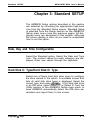
1
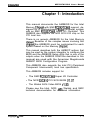
MPE-PNTM System Board
BIOS User’s Guide
P/N: 771920-DO2
Version DO2
August, 1994
Preface
MPE-PNTM BIOS User’s Guide
PREFACE
Thank you for your choice of a Mylex MPE-PNTM System Board
product. With proper installation and care, your Mylex System Board
will operate for years without any service requirement. This Installation
and Operation Guide will guide you in the installation process. The
information contained herein is subject to change without notice.
BIOS Modifications
For information on Mylex’s modifications to the AMIBIOS, please refer
to the “Appendix A” section of this manual.
Hardware
The MPE-PNTM motherboard uses the NCR53C810 PCI SCSI chip to
interface with standard/fast SCSI drives. The NCR53C810 resides on
the PCI bus allowing high-speed transfers from the SCSI drives.
Mylex does not represent or warrant that this Installations and Operations Guide is correct in any or all respects, and shall not be liable for
technical or editorial omissions or errors made herein. Except as
specifically provided herein, Mylex makes no warranties, express or
implied, respecting this guide or the Mylex products referred to herein,
including but not limited to any warranty of design, merchantability, or
fitness for a particular purpose, even if Mylex has been informed of
such purpose.
P/N: 771920~DO2
(DCopyright 1994
Mylex
bY
Corporation
P.O. Box 5035
Fremont, California 94537-5035
Copyright (0 1994
Version DO2
i
MPE-PNTM BIOS User’s Guide
Preface
Copyright Notice
This manual is copyrighted by Mylex Corporation. It may not, in whole
or in part, be copied, reproduced, photocopied, translated on paper,
electtvnic media or computer-readable-form or be used to make a
derivative work, without written permission from Mylex Corporation,
except as permitted by the United States Copyright Act of 7976, as
amended.
FCC Warning
This device has been tested and found to comply within the limits of a
Class B device, pursuant to Part 15 of FCC regulations. Operation is
subject to the following two conditions:
1)
This device may not cause harmful interference, and
2)
this device must accept any interference received, including interference that may cause undesired operation.
This equipment has been designed to provide reasonable protection
against harmful interference in a residential area. This equipment
generates, uses and can radiate radio frequency energy. This device,
if not installed and used in accordance with the manufacturer’s instructions, may cause harmful interference to radio communications. There
is no guarantee, however, interference will not occur in a particular
installation. Should it be determined that this equipment is causing
interference to radio or television reception, the following suggested
actions may be taken.
Reorient or relocate the receiving antenna. Increase the distance
between the antenna and the computer. Plug the computer into a
different AC outlet so that the two conflicting devices are using a
different branch circuit. Contact the dealer that sold this equipment
and/or a reputable radio/television service technician for additional
suggestions.
..
I
Version DO2
Copyright 0 1994
Preface
MPE-PNTM BIOS User’s Guide
CAUTION
Only equipment certified to comply with Class B (computer input/output
devices, terminals, printers, etc.) should be attached to this equipment,
and must have shielded interface cables.
Finally, any changes or modifications to the equipment by the user not
expressly approved by the guarantee or manufacturer could void the
users authority to operate such equipment.
Trademarks
Mylex and MPE-PNTM are registered trademarks of Mylex Corporation. All other products and companies are trademarks of their respective owners and licensees.
Mylex Warranty - Customer Service Policy
One Year Limited Warranty
This product is guaranteed to be free from manufacturing or material
defects for a period, of 1 (one) year after the date of purchase. Should
the product fail during this period Mylex will repair or replace (at Mylex’s
option) the product free of charge with the following provisions:
1)
Proof of purchase must be provided.
2)
The product must have been properly installed in accordance to the documentation provided.
3)
The product must not have been modified by any party
except by Mylex or an authorized agent.
4)
The product must be free of damage.
Any software, including firmware, is provided “as-is” without warranty
of any kind, expressed or implied. The purchaser bears complete risk
of the performance and quality of the software. Mylex’s sole responsi-
Copyright @ 1994
Version DO2
...
Ill
Preface
MPE-PNTM BIOS User’s Guide
bility, and the purchaser’s only remedy to any defect in workmanship,
shall be replacement of the defective medium (diskette or ROM).
All expressed or implied warranties for the MPE-PNTM, including, but
not limited to, warranties of merchantability and fitness for a particular
purpose, are restricted to the duration of the warranty period. Under
no circumstances shall Mylex be held liable, in any way, to the purchaser for damages, including any lost profits, lost savings, or other
incidental or consequential damages arising out of the use of, or
inability to use this product. Some states do not allow warranty or
liability restrictions or limitations, so the preceding limitations may not
apply to you.
Returned Merchandise Authorization (RMA)
All products returned to Mylex for warranty service or for other reasons,
must be assigned a RMA number before shipment to Mylex. The RMA
number may be obtained by contacting Mylex’s Technical Support
Department. Any product received without a RMA number will be
returned to the shipper unopened.
/mportanr Elofe: Only the company (or individual) that purchased the
product directly from Mylex may obtain an RMA number. If the Mylex
product was purchased from a reseller or distributor, you must contact
that company for service.
The following rules/procedures apply to all RMA’s:
1)
The product must be returned in original packaging or
other suitable materials.
2)
Each returned unit will be inspected for damage or other
irregularities. If a unit is shown to be modified, the
customer will be notified before any action is taken.
3)
Mylex will not be responsible for non-Mylex products
shipped with an RMA unit. This includes memory, math
co-processors and other internal and external peripherals.
Products must be shipped to Mylex with freight paid. Upon completion
of service, Mylex will ship the product back UPS Ground or similar
service, at no charge, unless prior arrangements have been made.
Iv
Version DO2
Copyright (0 1994
Preface
MPE-PNTM BIOS User’s Guide
Customer Service
Mylex Technical Support is available 8:00 a.m. to 500 p.m. pacific
standard time, Monday through Friday except holidays. They can be
reached at (510) 796-6100 or by FAX at (510) 7457715. If you
purchased a system with this board, please contact your system
supplier.
Copyright (Q 1994
Version DO2
V
MPE-PNTM BIOS User’s Guide
Table of Contents
Table of Contents
Chapter 1: Introduction
SystemBlOS..............................................l2
Configuration Data. ......................................... l-2
How Data is Configured ..................................... l-2
Types of AMIBIOS SETUP ................................... l-3
Chapter 2: PCI Local Bus
What PCI Accomplishes ..................................... 2-l
PCI Features . . . . . . . . . . . . . . . . . . . . . . . . . . . . . . . . . . . . . . . . . . . . . . 2-l
OtherPCIFeatures.........................................22
Buffered Read and Writes . . . . . . . . . . . . . . . . . . . . . . . . . . . . . . . . . . . . 2-3
Concurrent Operation ....................................... 2-3
Bus Mastering . . . . . . . . . . . . . . . . . . . . . . . . . . . . . . . . . . . . . . . . . . . . . 2-3
Burst Mode . . . . . . . . . . . . . . . . . . . . . . . . . . . . . . . . . . . . . . . . . . . . . . . 2-3
Multiplexing . . . . . . . . . . . . . . . . . . . . . . . . . . . . . . . . . . . . . . . . . . . . . . . 2-3
PCI Component Classes. .................................... 2-4
Chapter 3: Standard SETUP
Date, Day and Time Configuration ............................. 3-l
Hard Disk C: Type/Hard Disk D: Type ......................... 3-l
Entering Drive Parameters ................................... 3-2
Hard Disk Drive Types ...................................... 3-3
Using Auto Detect Hard Disk (only for IDE drives). ................ 3-5
Floppy Drive A:/Floppy Drive B: ............................... 3-5
Copyright Q 1994
Version DO2
vii
Table of Contents
MPE-PNTM BIOS User’s Manual
Chapter 4: Advanced SETUP
Default Settings. ........................................... 4-l
Optimal Defaults. ....................................... 4-l
Fail-Safe Defaults. ...................................... 4-l
Advanced SETUP Options. .................................. 4-2
Typematic Rate (CharsSec) .............................. 4-2
Mouse support . . . . . . . . . . .................................. 4-2
Above 1 MB Memory Test. . . . . . . . . . . . . . . . . . . . . . . . . . . . . . . . . . . . 4-2
Memory Test Tiik Sound . . . . . . . . . . . . . . . . . . . . . . . . . . . . . . . . . . . . 4-3
Parii Error Check. . . . . . . . . . . . . . . . . . . . . . . . . . . . . . . . . . . . . . . . . . 4-3
Hit “Del” Message Display . . . . . . . . . . . . . . . . . . . . . . . . . . . . . . . . . . . 4-3
Extended BIOS RAM Area. . . . . . . . . . . . . . . . . . . . . . . . . . . . . . . . . . . 4-4
Wait for “Fl” If Any Error . . . . . . . . . . . . . . . . . . . . . . . . . . . . . . . . . . . . 4-4
System Boot Up Num Lock . . . . . . . . . . . . . . . . . . . . . . . . . . . . . . . . . . 4-4
Floppy Drive Seek At Boot. . . . . . . . . . . . . . . . . . . . . . . . . . . . . . . . . . . 4-5
System Boot Up Sequence . . . . . . . . . . . . . . . . . . . . . . . . . . . . . . . . . . 4-5
System Boot Up CPU Speed ................................. 4-5
Cache Memory ............................................ 4-5
External Cache Mode. ...................................... 4-6
Adapter Shadow Cacheable. ................................. 4-6
System BIOS Shadow Cacheable ............................. 4-6
Password Checking ........................................ 4-6
ISA Video ROM COOO, 32K .................................. 4-7
IDE Block Mode ........................................... 4-8
Auto Keylock Timeout. ...................................... 4-6
Chapter 5: Chipset SETUP
Base Memory Size .........................................
Host-To-Host Memory Posting ................................
Host-To-PC1 Posting. .......................................
PCI-To-Memory Posting .....................................
DRAM Speed . . . . . . . . . . . . . . . . . . . . . . . . . . . . . . . . . . . . . . . . . . . . .
ISA VGA Frame Buffer Size. .................................
...
VIII
Version DO2
5-l
5-l
5-l
5-l
5-2
5-2
Copyright 0 1994
MPE-PNTM BIOS User’s Guide
Table of Contents
ISA VGA Frame Buffer Base Address (Memory Hole). ............. 5-3
ISAIRQ9 . . . . . . . . . . . . . . . . . . . . . . . . . . . . . . . . . . . . . . . . . . . . . . . . . 5-4
ISAIRQ10................................................55
ISAIRQll . . . . . . . . . . . . . . . . . . . . . . . . . . . . . . . . . . . . . . . . . . . . . . . . 5-5
ISAIRQ15................................................56
PCI VGA Palette Snooping. .................................. 5-6
On-Board PCI SCSI Controller. ............................... 5-6
PCISCSIBIOS . . . . . . . . . . . . . . . . . . . . . . . . . . . . . . . . . . . . . . . . . . . 5-6
PCI IDE Card Present In. .................................... 5-7
PCI IDE IRQ .............................................. 5-8
Chapter 6: Power Management SETUP
IDE Standby Power Down Mode .............................. 6-l
Chapter 7: Peripheral SETUP
Programming Mode. ........................................ 7-1
On-Board FDC. ............................................ 7-2
On-Board IDE Drive ........................................ 7-2
Serial Port l............................................... 7-2
Serial Port 2. .............................................. 7-3
Parallel Port. ......... J. ................................... 7-3
IRQ Active State ........................................... 7-3
IRQ Active State ........................................... 7-3
Parallel Port Mode. ......................................... 7-3
Copyright c8 1994
Version DO2
ix
MPE-PNTM BIOS User’s Manual
lMWhJCti0n
Chapter 1: Introduction
This manual documents the AMIBIOS for the Intel
Mercury Chipset with SMC FCD637C665 support, designed for a Pentium-based EISA computer system
with an SMC FDC637C665 Super I/O Controller. This
AMIBIOS also supports the NCR SCSI 810 chip on the
PCI local bus.
There is no generic AMIBIOS for the Intel Mercury
chipset. Because of the complex issues involving this
chipset, the AMIBIOS must be customized for each
system based on the Mercury chipset.
This manual describes both the AMIBCP options that
may be used by the system integrator to configure this
BIOS and the AMIBIOS Setup utility that is one of the
outputs when the AMIBIOS ROM files described in this
manual are used with the American Megatrends
AMIBCP BIOS Configuration Program.
This AMIBIOS also supports the Intel PCI (Peripheral
Component Interconnect) local bus specification.
This AMIBIOS includes support for:
l
l
l
The SMC FCD637C665 Super I/O Controller
The NCR 53C810 PCI SCSI BIOS V1.07
The Weitek 5816 Video BIOS ~1.50.
Please see the Intel, NCR, ATI, Weitek, and SMC
technical documentation for additional information.
Copyright (0 1994
Version DO2
l - l
Introduction
MPE-PNTM BIOS User’s Manud
System BIOS
The BIOS is the basic input output system used in all
IBM@ PC-, Xp -, AT@, and PS/2@ compatible computers. The AMIBIOS is a high-quality example of a
system BIOS.
Configuration Data
AT-Compatible systems, also called ISA (Industry
Standard Architecture) must have a place to store
system information when the computer is turned off.
The original IBM AT had 84 bytes of non-volatile memory storage in CMOS RAM. All AT-Compatible systems have at least 84 bytes of CMOS RAM, which is
usually part of the Real Time Clock. Many systems
have 128 bytes of CMOS RAM.
How Data Is Configured
AMIBIOS provides a Setup utility in ROM that is accessed by pressing <Del> at the appropriate time
during system boot. Setup configures data in CMOS
RAM.
The AMIBIOS Setup utility included in the AMIBIOS for
the Intel Mercury Chipset can also be executed via a
hot key.
1-2
Version DO2
Copyright (0 1994
Introduction
MPE-PNTM BIOS User’s Manual
Types of AMIBIOS Setup
;::. .:..:::..,.
,A., ,.,... . . . . . . . . ,.,.. .,. . . . . . .,. ,._., .;.
.~,~.~_~,~.~.~.~.~_~.~
.._.. ~.~.~.~.~_~_~.~.~_~.~.~.~.~.~.~.~.~.~.~.~,~.
:::::
,._.i,.,. .,.:. . ,. . . . . . ,.,. .,. ,. . ., ._.,. . . . . .,.
llijjiiiiiiiiiiiiiiiiiiiijijijiiiiiiiiii.
;:,. ::. _._.:, ., . . ,.,.,
. . . . . ._. . . ._ . ,.,. _. . .,. ._.,.,. .:,.,. .,., .: ,:. . .~,~.~.~.~.~.~.~.~_..~.~.~.~.~,.~.~.~.~.~,. ~.~.~.~.,~. ~.~.~.~.~.~.~.~.~.~.~.~.~.~ .:
:::.:::::::::::::::::::::::::::::::::::i:::::::::::::::::::::::::::::::::::::::::::::~:::~;:::::::::::::::::::::::::;::::::::::::::::::::::~:::~~::::
Standard SETUP
Sets time, date, hard disk type,
types of floppy drives, monitor
types, and if keyboard is
installed.
Advanced SETUP
Sets Typematic Rate and Delay,
Above 1MB Memory Test,
memory Test Tick Sound, Hit
<Del> Message Display, System
Boot Up Sequence, and many
others.
Chipset SETUP
Sets chipset-specific options and
features.
Peripheral SETUP
Controls l/O Controller-related
options.
Power Management SETUP
Controls power conservation
options.
.. . . . . . . . . . . . . . .~ ~. ~ .~_~. .~. ~ ~. .~. . . ~. .~. ~ ~. .~. ~ ~. .~._~.~.~.~.~.~.~.~.~.~.~.~. ~.~.~.~.~.~,~,. ~ _.: , .::: ;:. .: :::. .:::.. . ,. . . ._. .
:.,............................
. (..,_..,:.,. ,.:_._,. :(._(.._ ,.:,_.,. ,_.,._,. .,._,..,.,_.:,_. ,.:,.:,.,.,_., . . ,.:,.,:.. ,.:, . ,.,:.,.,. .,. .,..,.. ..,. ,.:, . .,., ,.,. _,.,,.,. .,. _,. .:,..,:. ., .,.,. . .,.,. .,.,. .,.,. .,. . .,.,.,.,. ..:..::::::.
. . . i.
:_i:i:;i.i:i.:.:~~~~~~~~~~~~~~~~~~~~~~i~~~~~~~~~~~~~~DE~R~~iolNii:.;~;i._..(i.ci:i~
,.,.,.,.,.,.,.,.,._.,.,. .,.,.,.,. .,. . .,.,. .,.,.,.,.,.,. . .,.,.,. .,.,.,.,.,.,.,.,.,. .,.,.,.,.,. .,.,. .,.,. .,.,.,.,.,.,.,.,.,.,.,.,. .,.,.,.,.,.,._. ,.,.,.,..,,..,,..,,..,,.,,..,(..,(..,,..,,..,,.,.,.,,..:,.:..:,.::..:.:.::..:+: :...:::
:.
,.,.I...._.::_.::::
.~...A...
::
::::.
.,,.,...
.,
.__.
.:
,,.,.,.,
,..
..:
.A..._... .::::::.
,.:.~:.:.:.:.:.:_:.:.:.:.:,:.:.:.:.:.~:.:.:.:.:.:.:.:.:.:.,._.,.,. ;._.?,.,.,.,.,._. :.,.: .,.;:.:.:.:.:.:.:.:.:.:.:.:.:.:.:.:.~:.:...~~~.:.:.:.:.:.~~,
:.:.
~.~.~.~.~.~.~.~.~.~.~.~.~.~.~.~.~.~.~.~.~.~~.~:~:~:.~:.:.:~:.:.’.~.‘.‘~‘.‘.‘.‘.‘.‘.‘.‘~‘.
..,.: ,A.,... ,...,.
Detect C
Autodetect IDE Drive
Detect D
I Autodetect IDE Drive
Colorset
Copyright Q 1994
..
Allows you to change the BIOS
Setup screen colors.
Version DO2
1-3
Introduction
MPE-PNTM BIOS User’s Manual
Password
Allows you to enter a userselected password that will
enable this option.
Antivirus
Enable/Disable antivirus
protection.
For default values.
Original
I Optimal
) For best performance.
I
I
l-4
Fail Safe
Version DO2
For safest default values
Copytig ht (B 1994
MPE-PNTM BIOS User’s Manual
PCI Local Bus
Chapter 2: PCI Local Bus
PCI is a specification for a local bus standard. The PCI
specification also provides the electrical specifications
for peripheral chip makers and the logic requirements
for a PCI Controller. While PCI defines a local bus
standard, it also defines a standard component-level
interface. PCI is a common I/O component interface.
The PCI Local Bus Specification is a standard set of
interface, architecture, timings, electrical, and physical
specifications that permits all PCI Local Bus products
to be totally interchangeable.
PCI is a multiplexed extension of the CPU bus. In PCI,
the CPU bus control mechanisms have been extended to optimize I/O support.
PCI establishes a local bus standard in which a large
variety of I/O components can be directly connected
without using any glue logic.
What PCI Accomplishes
PCI is a way to physically interconnect highly integrated peripheral components and processor/memory
systems.
PCI Features
Up to ten PCI loads can be used in the same system
on the PCI bus, including the PCI Controller and an
expansion bus controller for EISA, ISA, or MCA. PCI
decouples the CPU from the expansion bus and works
Copyright (0 1994
Version DO2
2- 1
MPE-PNTM BIOS User’s Manud
PCI Local Bus
at 33 MHz but can use either a 32-bit or 64-bit data
connection path to the CPU.
Other PCI Features
. Processor-independent,
. Has a multiplexed address, command, and data
bus and supports burst mode operation on reads
and wriies,
. Runs synchronous with the CPU at speeds up to 33
MHz,
. Has a maximum data transfer rate of 120 MBs (with
a peak rate of 132 MBs on a 32-bit data path),
. Has a maximum data transfer rate of 240 MBs (with
a peak rate of 264 MBs on a 64-bit data path),
. Has an optional 64-bit data path that is transpar-
ently interoperable with the 32-bit data path,
. Has low latency random accesses (about 60 ns
write access latency) to slave registers from a PCI
bus master on the PCI bus,
. Is capable of full concurrency with the processor
and PCI bus masters,
. Has full multimaster capability, allowing any PCI
Master peer-to-peer access to any PCI slave,
. Has hidden and overlapped central arbitration,
. Has a low pin count (master - 47; slave - 49,
. Has address and data parity, and
. Uses three physical address spaces: 32-bit mem-
ory, 32-bit I/O, and a 256 byte-per-agent configuration space.
2-2
Version DO2
Copyright @ 1994
MPE-PNTM BIOS User’s Manual
PCI Local Bus
Buffered Reads and Writes
The PCI Controller buffers reads and writes between
the memory/CPU and PCI peripheral devices.
Concurrent Operation
The CPU in a PCI system runs concurrently with PCI
bus mastering peripherals. Although bus mastering
peripheral devices are arbitrated, significant data
transfer rate improvements can be achieved without
splitting resource utilization between the CPU and a
bus mastering device. Peripheral devices can operate
at up to 33 MHz in a PCI environment.
Bus Mastering
PCI devices can be bus masters, slaves, or a combination of bus master and slave.
Burst Mode
The PCI specification also provides for burst mode of
any length for both reads and writes.
Multiplexing
PCI is a multiplexed bus. Multiplexing allows more
than one signal to be sent on the same electrical path.
Copyright (D 1994
Version DO2
2-3
PCI Local Bus
MPE-PNTM BIOS User’s Manual
The control mechanisms have been modified and extended to optimize l/O support.
PCI Component Classes
PCI components must be one of three classes:
l
Bus master,
0 Slave, or
l
2-4
Master/slave combination.
Version DO2
Copyright (0 1994
MPE-PNTM BIOS User’s Manual
Standard SETUP
Chapter 3: Standard SETUP
The AMIBIOS Setup options described in this section
are selected by choosing the appropriate high-level
icon from the Standard Setup screen. Standard Setup
is selected from the Setup section on the AMIBIOS
Setup main menu (see the previous page). All displayed icons are described in this section, although
the screen display is often all you need to understand
how to set the option.
Date, Day and Time Configuration
Select the Standard option. Select the Date and Time
icon. The current values for each category are displayed. Enter new values through the keyboard.
Hard Disk C: Type/Hard Disk D: Type
Select one of these hard disk drive icons to configure
the drive named in the option. A scrollable screen that
lists all valid disk drive types is displayed. Select the
correct type and press <Enteo. If the hard disk drive
is an IDE drive, select Detect C: or Detect D: from the
Utility section of the AMIBIOS Setup main menu to
have AMIBIOS automatically detect the IDE drive parameters and report them to this screen.
Copyright (0 1994
Version DO2
3-l
Standard SETUP
MPE-PNTM BIOS User’s Manual
Entering Drive Parameters
You can also enter the hard disk drive parameters. The
drive parameters are:
Tme
Cylinders
Heads
The number of cylinders in the
jisk drive.
The number of heads.
Write Precompensation
This size of a sector gets
xogressively smaller as the
rack diameter diminishes. Yet
2ach sector must still hold 512
Dytes. Wriie precomensation
5rcuitry on the hard disk
compensates for the physical
difference in sector size by
boosting the write current for
sectors on inner tracks. This
parameter is the track number
uvhere write precomensation
begins.
Landing Zone
The number OS the cylinder
location where the heads will
normally park when the system
is shut down.
Sectors
3-2
The number for a drive with
:ertain identification parameters.
The number of sectors per track.
MFM drives have 17 sectors per
track. RLL drives have 26
sectors per track. ESDI drives
have 34 sectors per track. SCSI
and IDE drives may have even
more sectors per track.
Version DO2
Copyright @ 1994
MPE-PNTM BIOS User’s Manual
Standard SETUP
Capacity
The formatted capacity of the
drive is (Number of heads) x
(Number of cylinders) x (Number
of sectors per track) x (512 bytes
per sector).
Hard Disk Drive Types
Not Installed
1 1
306
2
615
3
615
+
4 1
940
5
940
6
615
+
6
1
300
I
615
-t-+-k4 1
65535
I
1
I
256
17 1
62MB
17
47MB
615
17
20MB
511
17
31MB
733
17
30MB
901
17
112MB
7 1
462
8
8 1
733
5 1
900
15
820
3 1
65535
1
820
17
20MB
5 1
65535
1
855
17
35MB
65535
1
855
1
9
10
11
855
-+
12
1
855
7 1
13
I
306
8
14
(
733
7 (
Copyri9ht (Q 1994
65535
1
I
)
65535
1
128
65535
1
Version DO2
I
319
733
3-3
MPE-PNTM BIOS User’s Manual
Standard SETUP
34
612
2
128
612
17
10MB
35
1024
9
65535
1024
17
77MB
36
1024
8
512
1024
17
68MB
37
615
8
128
615
17
41MB
38
987
3
987
987
17
25MB
3-4
Version DO2
Copyright 0 1994
MPE-PNTM BIOS User’s
Standard SETUP
Manual
45
917
15
65585
918
17
114MB
46
1224
15
65585
1223
17
152MB
47
USER-DEFINED HARD DRIVE -- ENTER USERSUPPLIED PARAMETERS.
ESDI
SCSI
Using Auto Detect Hard Disk (Only for IDE Drives)
If you select Detect C: or Detect D: from the Utility
section of the AMIBIOS Setup main menu, AMIBIOS
automatically finds all IDE hard disk drive parameters.
AMIBIOS places the hard disk drive parameters that it
finds in the Drive C: Type or Drive D: Type fields in
Standard Setup.
Floppy Drive A:/Floppy Drive B:
Move the cursor to these fields via and and select the
floppy type. The settings are 360 KB 5bI4 inch, 7.2 MB
91’4 inch, 720 KB 31/z inch, 1.44 MB S1& inch, or 2.88
MB 3’/2 inch.
Copyright (0 1994
Version DO2
3-5
MPE-PNTM BIOS User’s Manual
Advanced SETUP
Chapter 4: Advanced SETUP
The Advanced Setup options that will be included in
the AMIBIOS Setup generated through AMIBCP and
the AMIBIOS for the Intel Mercury chipset with SMC
665 support are described in this chapter.
Although these options are described in the American
Megafrends AMIBIOS User’s Guide for the 12/l 5’93
coreAM/B/OS, they are also described in this manual,
since AMIBIOS is new and unfamiliar to most American megatrends clients.
Default Settings
Every option in AMIBIOS Setup contains two default
values: an Fail-Safe default and the Optimal default
value.
Optimal Defaults
The Optimal default values provide optimum performance settings for all devices and system features.
Fail-Safe Defaults
The Fail-Safe default settings consist of the safest set
of parameters. Use them if the system is behaving
erratically. They should always work but do not provide
optimal system performance characteristics.
Copyright (0 1994
Version DO2
4-l
MPE-PNTM BIOS User’s Manual
Advanced SETUP
Advanced Setup Options
Typematic Rate (CharslSec)
This option sets the rate at which characters displayed
on the screen repeat when a key is pressed and held
down. The settings are Disabled, 15,20, or 30 characters per second. The Optimal default setting is 30 cps.
The Fail-Safe default setting is Disabled.
Mouse SUDDOrt
When this option is set to Enabled, AMIBIOS supports
a PS/2-type mouse. The settings are Enabled or Disabled. The Optimal default setting is Enabled. The
Fail-Safe default setting is Disabled.
Use Disabled if a PS/2 mouse is not being used.
Above 1 MB Memory Test
When this option is set to Enabled, the AMIBIOS
memory test is performed on all system memory.
When this option is set to Disabled, the memory test
is done only on the first 1 MB of system memory. The
settings are Enabledor Disabled. The Optimal default
and Fail-Safe default settings are Disabled.
4-2
Version DO2
Copyright Q 1994
MPE-PNTM BIOS User’s Manud
Advanced SETUP
Memotv Test Tick Sound
This option enables (turns on) or disables (turns off)
the ticking sound during the memory test. The settings
are Enabled or Disabled. The Optimal defautt and
Fail-Safe default settings are Enabled.
Paritv Error Check
This option enables or disables parity error checking
for system RAM. The settings are Enabled (all system
RAM parity is checked) or Disabled (parity is checked
only on the first 1 MB of system RAM). The Optimal
defautt and Fail-Safe defautt settings are Disabled.
Hit “DEL” Message Display
Disabling this option prevents
Hit <Del> if you want to run Setup
from appearing when the system boots. The settings
are Enabled or Disabled. The Optimal default and
Fail-Safe default settings are Enabled.
Copyright 0 1994
Version DO2
4-3
MPE-PNTM BIOS User’s Manual
Advanced SETUP
Extended BIOS RAM Area
Specify in this option if the top 1 KB of the system
programming area beginning at 639K (DOS 7K) or
address 0:300 in the AMIBIOS area in low memory will
be used to store extended BIOS RAM information. The
settings are DOS IKor 0:300. The Optimal default and
Fail-Safe default settings are 0:300.
For extended BIOS RAM area, set this option to 0:300.
Wait for “Fl” If Any Error
AMIBIOS POST runs system diagnostic tests that can
generate a message followed by:
Press <Fl> to continue
If this option is set to Enabled, AMIBIOS waits for the
end user to press before continuing. If this option is
set to Disabled, AMIBIOS continues the boot process
without waiting for to be pressed. The settings are
Enabled or Disabled. The Optimal default and FailSafe default settings are Enabled.
System Boot Up Num Lock
When this option is set to On, AMIBIOS turns off Num
Lock when the system is powered on so the end user
can use the arrow keys on both the numeric keypad
and the keyboard. The settings are On or OH. The
Optimal default and Fail-Safe default settings are On.
4-4
Version DO2
Copyright (0 1994
MPE-PNTM BIOS User’s Manual
Advanced SETUP
Floppy Drive Seek At Boot
When this option is set to Enabled, AMIBIOS performs
a Seek command on floppy drive A: before booting the
system. The settings are Enabled or Disabled. The
Optimal default and Fail-Safe default settings are Disabled.
System Boot Up Sequence
This option sets the sequence of boot drives (either
floppy drive A: or hard disk drive C:) that AMIBIOS
attempts to boot from after AMIBIOS POST completes. The settings are C:,A: or A.$:. The Optimal
default setting is &A.-. The Fail-Safe default setting is
A:, C:.
Cache Memory
This option enables internal (on the microprocessor)
and secondary (external) cache memory. If Both is
selected, internal cache and external cache memory
is enabled. If Infernal is chosen, only the internal
cache memory in the Pentium CPU is enabled. If
Disabledis chosen, all cache memory is disabled. The
settings are Internal, Disabled, or Both. The Optimal
default setting is Both. The Fail-Safe default setting is
Disabled.
Copyright (D 1994
Version DO2
4-5
Advanced SETUP
MPE-PNTM BIOS User’s Manual
External Cache Mode
This option selects the type of caching algorithm used
by AMIBIOS and the computer for L2 (external) secondary cache memory. The settings are Wr-Thou or
W-Back. The Optimal default setting is Wr-Back. The
Fail-Safe default setting is Wr-Thm.
Adapter Shadow Cacheable
Once any Adapter BIOS is shadowed in RAM, using
the ISA Adapter ROM options, this option could be
used to cache the shadow RAM. Enable this option
only if all the adapters that have ROM shadowed,
work properly with this option disabled. If enabling this
option results in problems, immediately disable this. If
all the Adapter BIOS ROMs are not shadowed, leave
this option as disabled.
System BIOS Shadow Cacheable
If enabled, this option will make the BIOS area EOOO:O
to FFFF:F cachable. Disable this only for a fail safe
operation.
Password Checking
This option is only valid if the password is defined
under security. Options are Setup or Always. Setup
will only check the password when entering into
CMOS setup. Always will check the password when
booting.
4-6
Version DO2
Copyright Cp 1994
MPE-PNTM BIOS User’s Manual
Advanced SETUP
ISA Video ROM COW, 32K
When this option is set to Enabled, the video ROM
area from COOOOh - C7FFFh is copied (shadowed)
from ROM to RAM for faster execution. The settings
are Absent, Present, or Shadow.
l
l
l
l
l
ISA Adapter ROM C800,16K
ISA Adapter ROM CCOO,16K
ISA Adapter ROM DO00,16K
ISA Adapter ROM D400,16K
ISA Adapter ROM D800,16K
These options enable shadowing of the contents of
the ROM area beginning at the address named in the
option title (for example, the Shadow 0, 16K option can enable shadowing of the contents of the ROM
area from C8000h - CBFFFh to RAM. The settings
are Absent, Present, or Shadow. The ROM area that
is not used by ISA adapter cards will be allocated to
PCI adapter cards.
If no ISA adapter ROM exists at the location, make
sure the option is marked as Absent, so that the PCI
boards can be automatically configured to use these
ROM areas.
If the option is set to Present, it means there is an ISA
adapter ROM present in this address and the ISA
adapter ROM will not be shadowed and this address
can not be used for PCI option ROM. If the option is
set to Shadow, it means there is a ISA adapter ROM
present in this address and ISA adapter ROM will be
shadowed. Therefore, this address cannot be used
for PCI option ROM.
Copyright (0 1994
Version DO2
4-7
Advanced SETUP
MPE-PNTM BIOS User’s Manual
IDE Block Mode
This option enables multiple sector reads and writes
for IDE drives. The settings are EnaMedor Disabled.
The Optimal default setting is Disabled. The Fail-Safe
defautt setting is Enabled.
WARNING!
Do not enable this option if the IDE hard disk does
not support block mode. File corruption will result.
4-0
Version DO2
Copyright a3 1994
MPE-PNTM BIOS User’s Manual
Chioset SETUP
Chapter 5: Chipset Setup
Base Memory Size
This option sets the size of the base system memory.
The settings are 512 KB or 640 KB. The Optimal and
Fail-Safe default settings are 640 KB.
Host-To-Host Memory Posting
The settings are Enabled or Disabled. The Optimal
and Fail-Safe default settings are Disabled.
If any bus mastering boards are in the system, the
host-to-host memory posting must be set to disabled.
Host-To-PC1 Posting
Enable this option for better performance.
PCI-To-Memory Posting
The settings are Enabled or Disabled. The Optimal
and Fail-Safe default settings are Disabled.
Enable this option for better performance.
Copyright ((3 1994
Version DO2
5-1
Chipset SETUP
MPE-PNTM BIOS User’s Manual
DRAM Speed
This option specifies the type of DRAM system memory used in this computer. The settings are Slow or
Fast. The Optimal and Fail-Safe default settings are
Slow.
This setting is a future option. Do not enable.
ISA VGA Frame Buffer Size
This option must be set to Enabled if the VGA adapter
card installed in the system requires a frame buffer.
This option sets the size of the VGA frame buffer. The
settings are Disabled, 7 MB, 2 MB, or 4 MB. The
Optimal and Fail-Safe default settings are Disabled.
5-2
Version DO2
Copyright (D 1994
MPE-PNTM BIOS User’s Manud
Chipset SETUP
ISA VGA Frame Buffer Base Address (Memory Hole)
This option sets the base address (or starting point) of
the VGA frame buffer. This option must be set to
Enabled if the VGA card installed in the system requires a frame buffer. The settings are dependent on
the setting of the ISA VGA Frame Buffer Size option
as shown in the following table.Also see the table to
create a memory hole below 16MB.
Disabled
I
N/A
I
1MB
I
15MB - 16MB
I
2MB
I
14MB - 16MB
I
4MB
I
12MB - 16MB
I
The Optimal and Fail-Safe default settings are (MA).
Copyright (D 1994
Version DO2
5-3
MPE-PNTM BIOS User’s Manud
Chipset SETUP
ISA IRQ 9
IRQ x: Four setup options are available for PCI IRQs;
i.e., the IRQs that can be assigned to PCI devices.
They are IRQ9, IRQl 0, IRQll , and IRQ15. The setup
option for each IRQ is either ‘ISA’ or ‘PCI’. When set
to ‘ISA’, the designated IRQ is not available for PCI
devices and. If set to ‘PCI’, the designated IRQ will be
available for PCI devices.
The IRQs that are available for PCI devices are albcated in the following manner,
First, all available IRQs are allocated to the PCI devices so that the interrupt does not have to share. If
there are no more available IRQ numbers, then an
already-used IRQ will be allocated, in which case that
IRQ must be sharable. For example, if two PCI cards
are present and if IRQ9, IRQlO, and IRQll are available for PCI, then the on-board SCSI PCI card in slot
land the PCI card in slot 2 each will be allocated a
unique IRQ. But if only two IRQsare available, such as
IRQ9 and IRQll , then IRQ9 must be sharable.
The on-board SCSI port in the Pentium Motherboard
actually sits on the PCI bus, without taking up any PCI
slots.
Note: The on-board SCSI port, enabled through the
on-board PCI SCSI device option, will consume an
interrupt. Hence, if the on-board SCSI port is enabled,
make sure an IRQ is made available to it, by assigning
it to PCI. IRQ9 should be set to ISA.
PCI IRQ: Set to Level normally. This setting also
allows sharing of PCI interrupts. Make sure all the PCI
cards can operate with the setting defined here.
5-4
Version DO2
Copyright (23 1994
MPE-PNTM BIOS User’s Manual
ChiPset SETUP
At least one IRQ must be free for each PCI adapter
card in the system. If the PCI adapter card includes a
multifunction device, at least two or more IRQs must
be free. The settings are Free or Used. The Optimal
and Fail-Safe default settings are Free.
Set IRQ9 to ISA when using the on-board NCR
SCSI.
ISA IRQ 10
At least one IRQ must be free for each PCI adapter
card in the system. If the PCI adapter card includes a
multifunction device, at least two or more IRQs must
be free. This option specifies if IRQ 10 is used in ISA.
The settings are Free or Used. The Optimal and FailSafe default settings are Free.
ISAIRQll
At least one IRQ must be free for each PCI adapter
card in the system. If the PCI adapter card includes a
multifunction device, at least two or more IRQs must
be free. This option specifies if IRQ 11 is used in ISA.
The settings are Free or Used. The Optimal and FailSafe default settings are Used.
Copyright Q 1994
Version DO2
5-5
MPE-PNTM BIOS User’s Manual
Chipset SETUP
ISA IRQ 15
At least one IRQ must be free for each ISA adapter
card in the system. If the PCI adapter card includes a
multifunction device, at least two or more IRQs must
be free. This option specifies if IRQ 15 is used in ISA.
The settings are Free or Used. The Optimal and FailSafe default settings are Free.
PCI VGA Palette Snooping
This option must be set to Enabled if any ISA adapter
card installed in the system requires VGA palette
snooping. The settings are Enabled or Disabled. The
Optimal and Fail-Safe default settings are Disabled.
On-Board PCI SCSI Controller
Set this option to Enabled to use the PCI Controller on
the motherboard. The settings are Enabled or Disabled. The Optimal default setting is Enabled. The
Fail-Safe default setting is Disabled.
PCI SCSI BIOS
Set this option to Enabled to enable the PCI SCSI
BIOS. The settings are Enabled or Disabled. The
Optimal default setting is Enabled. The Fail-Safe default setting is Disabled.
5-6
Version DO2
Copyright 0 1994
MPE-PNTM BIOS User’s Manual
Chips& SETUP
PCI IDE Card Present In
The default is Absent. The motherboard contains an
on-board IDE interface. However, if a PCI IDE expansion card is plugged in, this option will have to be set.
The above option supports the PCI IDE cards (which
are not truly PCI compliant). The PCI IDE card’s slot
number needs to be specified for this purpose. The
examples given below explain all the possible options.
l
l
l
If a PCI IDE card without any configuration space
(so there is no means by which BIOS can identify
this card as PCI card) is used, BIOS will assume
that I/O ports 1 FO-lF7, I/O Ports 3F6-3F7 and
IRQ14 are used by this card. The PCI IDE card’s
slot number needs to be specified for such a card.
If a PCI IDE card with a READ ONLY configuration
space (so BIOS can see this card as PCI card but
can’t program the configuration space), BIOS will
assume that I/O ports 1 FO-1 F7, I/O Ports 3F6-3F7
and IRQ14 are used by this card. In this case, user
NEED NOT specify the presence of the card in
setup since it can be identified by BIOS as PCI IDE
card.
For a true PCI IDE card without option ROM, BIOS
will allocate I/O ports 1 FO-1 F7, I/O Ports 3F6-3F7
and lRQ14 to this card. The PCI IDE card’s slot
number needs to be specified for such a card.
For a true PCI IDE card with an option ROM, BIOS
will automatically configure the IDE card as a true PCI
device assuming the option ROM is capable of handling allocated resources properly. and IRQ14 are
used by this card. The PCI IDE card’s slot number
needs to be specified for such a card.
This option specifies which PCI expansion slot the
on-board IDE controller is attached to. The settings
are Absent, Slot 1, Slot 2, Slot 3. The Optimal and
Fail-Safe default settings are Absent.
Copyright (0 1994
Version DO2
5-7
Chipset SETUP
MPE-PNTM BIOS User’s Manual
PCI IDE IRQ Connect To
This option specifies the interrupts used by the onboard PCI IDE controller connected to one of the
available IRQs. Settings are /NT A (70), /NT B (711,
/NT C (12), INT D (13).
5-8
Version DO2
Copyright (Q 1994
MPE-PNTM BIOS User’s Manual
Power Management SETUP
Chapter 6: Power Management SETUP
The WinBlOS Setup options described in this section
are selected by choosing the appropriate option from
the Power Mgmt Setup screen. Power Mgmt Setup is
selected from the Setup section on the WinBlOS
Setup main menu. All options are described in this
section. A sample Power Management Setup screen
is shown below.
AMIBCP VW 3.3 - AMIBIOS POSTCONFIGURATION MENU
(C) Capyrcghl1993 American Megf@endr, Inc. Al Ri@ts Rosmd
I
I
-
Power Management Setup
IDE8lMdbyP-DownMod.:
-I/
IDE Standby Power Down Mode
This option specifies the length of time of hard disk
drive inactivity that must expire before the IDE hard
disk drive is placed in IDE Standby Power Down
Mode. The settings are Enabled or Disabled. The
Optimal and Fail-Safe default settings are Disabled.
Copyright (0 1994
Version DO2
6-l
MPE-PNTM BIOS User’s Manual
PetiDheral SETUP
Chapter 7: Peripheral Setup
The WinBlOS Setup options described in this section
are selected by choosing the option from the Peripheral Setup screen. Peripheral Setup is selected from
the Setup section on the WinBlOS Setup main menu.
Programming Mode
The settings are Auto or Manual. When set to Auto,
WinBlOS automatically detects all adapter cards installed in the system and configures the onboard I/O
(serial ports, parallel ports, floppy controllers, and IDE
controller) automatically. All other Peripheral Setup
option settings are ignored. Any serial port, parallel
port, floppy controller, or IDE (Integrated Drive Electronics) controller on an adapter card in an expansion
slot is configured before onboard I/O. If Auto is selected, WinBlOS also attempts to avoid IRQ conflicts.
If the offboard serial ports are configured to specific
starting I/O ports via jumper settings, WinBlOS confiiures the onboard serial ports to avoid conflicts. For
example, if the default serial port starting I/O ports
(serial port1 - 3F8h, serial port2 - 2F8h, serial port3 3E8h, serial port4 - 2E8h) are, the following configurations are possible:
two off -board serial
ports
3E8h and 2F8h
3E8h and 2E8h
two off-board serial
ports
3F8h and 3E8h
3F8h and Disabled
Copyright @ 1994
Version DO2
7- 1
MPE-PNTM BIOS User’s Manual
Peripheral SETUP
one off-board serial
port
2F8h
3F8h and Disabled
one off-board serial
port
3F8h
2F8h Disabled
If Manual is selected, the settings chosen by the end
user in Peripheral Setup%pply. WinBlOS reports any
I/O conflicts after displaying the BIOS Configuration
Summary Screen, but only if Manual is chosen. The
Optimal and Fail-Safe default settings are Auto.
On-Board FDC
This option enables the use of the FDC (Floppy Drive
Controller) on the motherboard (if installed). The settings are Enabled or Disabled. The Optimal and FailSafe default settings are Disabled.
On-Board IDE Drive
This option enables the use of the IDE controller on
the motherboard (if installed). The settings are Enabled or Disabled. The Optimal and Fail-Safe default
settings are Disabled.
Serial Port 1
This option enables serial port 1 on the motherboard
(if installed). The settings are 2E8h. The Optimal and
Fail-Safe defaults are 3F8h.
7-2
Version DO2
Copyright (D 1994
MPE-PNTM BIOS User’s Manual
Peridwal SETUP
Serial Port 2
This option enables serial port 2 on the motherboard,
if installed. The settings are Z/WI. The Optimal and
Fail-Safe default settings are 2F8h.
Parallel Port
This option enables the parallel port on the motherboard, if installed. The settings are 378h. The Optimal
and Fail-Safe default settings are 378h.
IRQ Active State
This option specifies if the parallel and serial port IRQs
are active high or active low. The settings are Low or
High. The Optimal and Fail-Safe default settings are
High.
Parallel Port Mode
This option specifies the parallel port mode. The settings are Norma/ or Extended. The Optimal and FailSafe default settings are Normal.
Copyright 0 1994
Version DO2
7-3