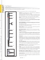
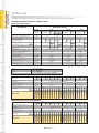
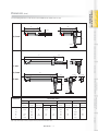
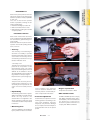
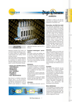
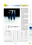
1
Red Crown™ product line offers:
•
•
•
•
•
Comprehensive product range
High quality and precision
Competitive price
Short delivery
Durability
Red Crown™ pencil probes - the
easiest choice to gauge your part.
BORE GAUGES LINE
FORKS AND RING GAUGES
Reliability and durability are assured
in all models through innovative
design and the use of the most
suitable materials, developed thanks
to TESTAR’s extensive experience in
the quality control sector.
Red Crown pencil probes assure
precision measurements, even
below one micron, and contribute to
the quality of measurement data.
TRANSDUCERS AND
MEASUREMENT TRANSMISSIONS
compatible configuration.
Compatible line:
A comprehensive list of probes
Soft touch line:
Pencil probes especially designed
with very low measuring force to
directly gauge delicate parts such
as glass, TV tubes, car windshields
and plastic material. These probes
can be supplied in basic or
TESTAR, which has ISO 9000
certification, manufactures every
pencil probe to the strictest quality
standards, on the basis of its own
experience and in accordance with
the quality that a measuring
instrument must provide.
The Red Crown product is 100%
tested, following internationally
recognized procedures and using
computerized equipment which
define the basic product parameters.
INDICATORS AND ELECTRONIC
DISPLAY UNITS
Basic line:
A family of 52 standard models
covering a measuring range from
± 0,5 to ± 5 mm. The pencil probes
are supplied with full-bridge (LVDT)
or half-bridge (HBT) transducer
already calibrated for connection to
any TESTAR electronic display units
such as E18, E4, E4N, Quick Read
Microcolumn and, through the
data acquisition systems Easy Box
and Gage Box ™ to E9066s ™
Industrial PC.
Unplugged line:
The 52 standard models of the basic
line can also be provided without
connector. Based on established
electrical characteristics supplied
with each probe the user can add
the necessary connector and
perform the appropriate calibration
to the electronics in use.
TESTAR’s technical team has over
thirty years of experience in the
manufacture and use of pencil
probes for its own applications and
those of third parties. Knowledge of
the manufacturing workshop
environment was essential to the
development of the Red Crown
product line.
INTERFACE BOXES
FOR DATA ACQUISITION
The Red Crown™ pencil probe line
developed by TESTAR, a Marposs
division, to fulfil quality control
requirements in the workshop is
available in four variants:
covering the TESTAR standard
measuring ranges with appropriate
electrical connector and calibrated
to comply with your existing
electronic display unit.
SOFTWARES
PENCIL PROBES LINE
BENCH GAUGES
QUALITY GUARANTEE
RED CROWN - 1
TRANSDUCERS AND
MEASUREMENT TRANSMISSIONS
THE PRODUCT
TESTAR experience has allowed the development of the Red Crown product line, a product with innovative
features that satisfies the most demanding market standards.
Red Crown pencil probes consist of the following basic parts:
1
- Contact. Interchangeable ( M2,5 or 4-48 UNF thread - standard model made of tungsten carbide, R=1,5 mm).
A wide range of optional contacts is available, to suit all specific measuring requirements. The “soft touch” models are typically supplied
with interchangeable nylon contact to prevent surface damage.
3
2
- Gaiter. It is made of rubber (Fluoroelastomer) and protects the internal mechan-ical parts from dust or liquids (IP65).
It allows the product to function in the workshop, even in the harshest conditions. The “soft touch” models are provided without gaiter
for consistent low measuring force.
4
3
- Pencil probe body. The stainless steel body has a hardened surface, to prevent damage to mechanical sliding parts in the event of
high tightening torques.
The entire range of pencil probes includes versions with an external
body diameter of both 8h6 mm and 3/8”.
4
- Guide system. Mounted on ball bearings, guaranteeing optimum
sliding movement of the mechanical parts.
5
- Anti-rotation feature. Facilitates contact assembly/disassembly.
6
- Spring. Determines the measuring force with which the contact
touches the workpiece.
In addition to the standard spring normally supplied, there is a wide
range of optional springs, for a greater or lower measuring force.
The “soft touch” models are provided with special spring type to
allow low measuring force (0,30 N at electrical zero with horizontal
probe axis).
8
7
- Transducer. The transducer is made using high tech materials and
production processes, which guarantee great precision. It is available
in two configurations, full-bridge (LVDT) and half-bridge (HBT), allowing
customization of the pencil probes to suit any electronic system on
the market.
9
8
- Pre-travel adjustment. This device allows optimum adjustment of tangential interference with the workpiece to be checked. Pre-travel adjustment extends the life of the sliding parts inside the pencil probe.
9
- Cable spring. Always present , the cable spring guarantees an optimum cable curve radius, preventing damage.
1
BORE GAUGES LINE
2
FORKS AND RING GAUGES
5
6
BENCH GAUGES
7
INDICATORS AND ELECTRONIC
DISPLAY UNITS
INTERFACE BOXES
FOR DATA ACQUISITION
10
10 - Cable. The 2 meters cable (EMC standards - directive 89/336/EEC)
is highly resistant to tears and is covered with a sheath made of
special material highly resistant to coolants. The cable outlet may be
axial or radial. Extensions of various lengths are also available.
SOFTWARES
11
11 - Pneumatic push - Vacuum retract. Some models can be fitted
with a manual or automatic pneumatic device to retract the contact
(vacuum retract) or to move the contact to the measuring position
(pneumatic push).
These functions are particularly useful for automatic applications.
The “soft touch” models are designed to guarantee a tip force at
electrical zero of 0,18 N.
RED CROWN - 2
SOFTWARES
INTERFACE BOXES
FOR DATA ACQUISITION
INDICATORS AND ELECTRONIC
DISPLAY UNITS
BENCH GAUGES
FORKS AND RING GAUGES
BORE GAUGES LINE
TRANSDUCERS AND
MEASUREMENT TRANSMISSIONS
EXAMPLES OF APPLICATIONS
RED CROWN - 3
The basic Red Crown product line includes 52 models to satisfy the various market needs.
TECHNICAL SPECIFICATIONS / ORDER CODES
Mechanical specifications
MEASURING RANGE
DESCRIPTION
± 0,5 mm
± 1mm
Pre-travel at electrical zero (mm)
Overtravel from electrical zero (mm)
Pre-travel adjustment
Pneumatic Push (PP)
Vacuum Retract (VR)
Standard
0,6/0,7
* 0,65
Yes
-
VR(*)
PP
VR(*)
PP
-
VR(*)
5,1/5,2
* 5,1
Yes
PP
-
0,4 ÷1
6 ÷14,5
0,08
0,03
0,7
0,6 ÷ 2,3
ball bearing
) 0,2
IP65
1,5
Yes
) 25 (0,5%)
) 0,25
-10 +65
Fluoroelastomer
SV50/6
2
VR(*)
PP
0,4 ÷1
6 ÷14,5
0,06
0,02
0,7
0,7 ÷ 2,4
ball bearing
) 0,4
IP65
1,5
Yes
) 50 (0,5%)
) 0,5
-10 +65
Fluoroelastomer
SV50/6
2
±1 VR
±1 LR
±2,5 VR
±5 VR
spring 1024099711
spring 1024099735
spring 1024099721
spring 1024099735 + spring-guide 1024099660
Full-bridge (LVDT) electrical specifications
FR50
7,5
FP50
9
) 10°
115 ±1%
3441558005
3441558004
3441558002
3441558003
3441556005
3441556004
3441556002
3441558001
ø 8 ø 3/8" ø 8 ø 3/8"
ø 8 ø 3/8" ø 8 ø 3/8"
3441556000
3441554004
3441554009
3441554003
3441554008
3441554002
3441554007
3441554001
3441554006
3441554000
3441554005
F50
ø 8 ø 3/8"
ø 8 ø 3/8"
ø 8 ø 3/8" ø 8 ø 3/8" ø 8 ø 3/8" ø 8 ø 3/8"
3441556001
ø 8 ø 3/8"
3441552001
Order Code
ø 8 ø 3/8"
ø 8 ø 3/8"
3441552003
axial
radial
F25
FP10 FR11 FP11
FR25 FP25
7,5
7,5
3,5V RMS with load 1MOhm //360 pF
9
9
) 10°
) 10°
230 ±1%
115 ±1%
3441558000
FR10
9
) 10°
230 ±1%
3441552000
RED CROWN - 4
HR50
7,5
HP50
5
) 5°
29,5 ±1%
3441557005
3441557004
3441557002
3441557003
3441555005
3441555004
3441555002
3441557001
ø 8 ø 3/8" ø 8 ø 3/8"
ø 8 ø 3/8" ø 8 ø 3/8"
3441555000
3441553009
3441553008
3441553004
3441553003
3441553005
N OTE : The User manual is included in the package.
H50
ø 8 ø 3/8"
ø 8 ø 3/8"
ø 8 ø 3/8" ø 8 ø 3/8" ø 8 ø 3/8" ø 8 ø 3/8"
3441555001
ø 8 ø 3/8"
ø 8 ø 3/8"
3441553006
ø 8 ø 3/8"
3441553001
axial
radial
H25
HP10 HR11 HP11
HR25 HP25
7,5
7,5
3,5V RMS with load 2 KOhm ± 0,1%
5
5
) 5°
) 5°
73,75 ±1%
36,9 ±1%
3441557000
5
) 5°
73,75 ±1%
3441553000
SOFTWARES
Order Code
HR10
3441553002
Calibration frequency (KHz)
Calibrated at
Max. current (mA RMS)
I/O phase shift
Sensitivity (mV/V/mm)
Cable outlet
H10
HR05
7,5
3441555003
H05
Trade name
3441551001
INTERFACE BOXES
FOR DATA ACQUISITION
Half-bridge (HBT) electrical specifications
3441551003
INDICATORS AND ELECTRONIC
DISPLAY UNITS
Calibration frequency (KHz)
Calibrated at
Max. current (mA RMS)
I/O phase shift
Sensitivity (mV/V/mm)
Cable outlet
F10
FR05
7,5
3441556003
F05
Trade name
3441552002
BENCH GAUGES
(*) The Vacuum Retract function (contact pneumatic retraction) can be added by using the accessories code 4430245031 or 4430240679. It is also
necessary to substitute the standard springs with the following ones:
3441551000
FORKS AND RING GAUGES
0,4 ÷1
0,5 ÷1
6 ÷14,5
7,3 ÷14,5
0,14
0,08
0,1
0,02
0,75
0,8 ÷ 2,5
0,7
0,5 ÷ 2
ball bearing
) 0,15
) 0,3
IP65
1,5
Yes
) 5 (0,25%)
) 0,25
-10 +65
Fluoroelastomer
SV50/6
2
Pneum.
Push
Standard
2,6/2,7
*3
Yes
*9
Yes
-
± 5mm
Pneum.
Push
Standard
1,1/1,2
* 1,5
bar
Operating pressure
psi
N
Standard spring strength ( /mm ± 15%)
0,17
Tip force at electrical zero (N ± 25%)
1
Guide system
ball bearing
Repeatability (m x 2,77) (+m)
) 0,15
Degree of protection CEI/IEC 529
IP65
Standard contact (R...mm)
1,5
Optional contacts
Yes
Linearity error (+m)
) 3 (0,3%)
Thermal drift at zero (+m/°C)
) 0,25
Operating temperature (°C)
-10 +65
Standard gaiter
Fluoroelastomer
Std. connector (DIN 45322) Lumberg
SV50/6
Cable length (m)
2
3441551002
BORE GAUGES LINE
Standard
± 2,5mm
Pneum. Long Range (LR)
Push Standard P. Push
3441553007
TRANSDUCERS AND
MEASUREMENT TRANSMISSIONS
THE BASIC LINE
TRANSDUCERS AND
MEASUREMENT TRANSMISSIONS
DIMENSIONS (mm)
The clamping diameter of all versions is available both as 8h6 mm or 3/8”.
A1
C
B
D
B
C
ø 3,8
9
9
± 0,5 mm
22
BORE GAUGES LINE
A
22
A
C
FORKS AND RING GAUGES
ø 3,8
A2
D
B
(**)
A1
C
B
9,5
7,4 (*)
1,2
± 5 mm
7,4 (*)
INDICATORS AND ELECTRONIC
DISPLAY UNITS
9
22
ø 3,8
ø 3,8
MEASURING RANGE
DIMENSIONS
± 0,5 mm
± 1mm
± 2,5mm
± 5mm
Long Range (LR)
Standard
Standard
Pneum. Push
Standard
Pneum. Push
A
39,2
80
-
-
-
92,5
-
118
-
A1
42.8
86
86
116,6
116,6
98,9
98,9
124
124
A2
-
92,5
-
-
-
105
-
130,5
-
B
19,2
57
57
76
76
68
68
84,5
84,5
C
9,2
13,5
13,5
25
25
15
15
21
21
D
10,8
9,5
-
-
-
9,5
-
12,5
-
(*) For pneumatic version only.
(**) Right cable adapter is always supplied with the probes with axial cable outlet.
RED CROWN - 5
Standard
Pneum. Push
Standard
Pneum. Push
A / A1 / A2 / C refer to the electrical zero
INTERFACE BOXES
FOR DATA ACQUISITION
± 2,5 mm
BENCH GAUGES
ø 3,8
SOFTWARES
± 1 mm
TRANSDUCERS AND
MEASUREMENT TRANSMISSIONS
COMPATIBLE LINE
TESTAR has developed a number of Red Crown models with the required connector and calibration, ready to
be used as replacement of non-TESTAR probes. This allows the user to take advantage of the latest technology
designed in the Red Crown product without the need to replace the existing electronic unit.
For mechanical specifications and dimensions of these probes see the corresponding model in the basic line.
This line is in continuous development and you can find the latest list of products with order codes by visiting our
web site www.testar.com
BORE GAUGES LINE
MEASURING RANGE
BASIC MODELS
MANUFACTURER
± 0,5 mm
TRANSD.
TYPE Ø
H05
± 1 mm
LONG RANGE
± 1 mm
HR05
H10
HR10
HR11
± 2,5 mm
H25
± 5 mm
HR25
H50
HR50
FORKS AND RING GAUGES
TESA
8 3441561000 3441561001 3441561002 3441561003 (*) 3441561005 (*) 3441561007 3441561008 (*) 3441561010 3441561011 (*)
MERCER
8 3441564000 3441564001 3441564002 3441564003 (*) 3441564005 (*) 3441564007 3441564008 (*) 3441564010 3441564011 (*)
METEM
8 3441569000 3441569001 3441569002 3441569003 (*) 3441569005 (*) 3441569007 3441569008 (*) 3441569010 3441569011 (*)
METREL
MAHR-FEINPRUEF
HALF-BRIDGE
(HBT)
8 3441563000 3441563001 3441563002 3441563003 (*) 3441563005 (*) 3441563007 3441563008 (*)
-
8 3441567000 3441567001 3441567002 3441567003 (*) 3441567005 (*) 3441567007 3441567008 (*) 3441567010 3441567011 (*)
NOVIBRA
8
MACHSIZE-SYSTEM E
BENCH GAUGES
AIR GAGE
-
-
-
-
-
-
-
-
-
8 3441562009 3441562010 3441562008 3441562011
3441562013
-
-
-
-
3/8" 3441562000 3441562001 3441562002 3441562003 (*)
-
-
-
F50
FR50
MANUFACTURER
TRANSD.
Ø
TYPE
ETAMIC (ZDB)
FULL-BRIDGE
(LVDT)
F05
FR5
3441568003
F10
FR10
FR11
8 3441565009 3441565010 3441565006 3441565011
3441562005 3441562006 (*)
F25
3441565013 3441565007
FR25
3441565015 3441565008
3441565017
(*) The Vacuum Retract function (contact pneumatic retraction) can be added by using the accessories code 4430245031 or 4430240679. It is also
necessary to substitute the standard springs with the one reported in the table on page 4.
INDICATORS AND ELECTRONIC
DISPLAY UNITS
MEASURING RANGE
PNEUMATIC PUSH
MODELS
MANUFACTURER
TRANSD.
TYPE Ø
± 1 mm
± 1 mm
LONG RANGE
± 2,5 mm
± 5 mm
HP10
HP11
HP25
HP50
INTERFACE BOXES
FOR DATA ACQUISITION
TESA
8
3441561004
3441561006
3441561009
3441561012
MERCER
8
3441564004
3441564006
3441564009
3441564012
8
3441569004
3441569006
3441569009
3441569012
8
3441563004
3441563006
3441563009
-
MAHR-FEINPRUEF
8
3441567004
3441567006
3441567009
3441567012
MACHSIZE-SYSTEM E
8
3441562012
3441562014
-
-
3/8"
3441562004
-
3441562007
-
FP10
FP11
FP25
FP50
3441565012
3441565014
3441565016
3441565018
METEM
METREL
HALF-BRIDGE
(HBT)
AIR GAGE
SOFTWARES
MANUFACTURER
TRANSD.
TYPE Ø
ETAMIC (ZDB)
FULL-BRIDGE
(LVDT)
8
N OTE : The User manual is included in the package.
RED CROWN - 6
0,6/0,7
* 0,65
Yes
1,1/1,2
* 1,5
2,6/2,7
*3
Yes
*9
Yes
-
-
VR(*)
PP
VR(*)
PP
-
0,4 ÷1
0,5 ÷1
6 ÷14,5
7,3 ÷14,5
0,14
0,08
0,10
0,02
0,75
0,8 ÷ 2,5
0,7
0,5 ÷ 2
ball bearing
) 0,15
) 0,3
IP65
1,5
Yes
) 0,25
-10 +65
Fluoroelastomer
3,5
bar
Operating pressure
psi
N
Standard spring strength ( /mm ± 15%)
0,17
Tip force at electrical zero (N ± 25%)
1
Guide system
ball bearing
Repeatability (m x 2,77) (+m)
) 0,15
Degree of protection CEI/IEC 529
IP65
Standard contact (R...mm)
1,5
Optional contacts
Yes
Thermal drift at zero (+m/°C)
) 0,25
Operating temperature (°C)
-10 +65
Standard gaiter
Fluoroelastomer
Cable length (m)
3,5
VR(*)
Pneum.
Push
Standard
5,1/5,2
* 5,1
Yes
PP
-
0,4 ÷1
6 ÷14,5
0,08
0,03
0,7
0,6 ÷ 2,3
ball bearing
) 0,2
IP65
1,5
Yes
) 0,25
-10 +65
Fluoroelastomer
3,5
VR(*)
PP
0,4 ÷1
6 ÷14,5
0,06
0,02
0,7
0,7 ÷ 2,4
ball bearing
) 0,4
IP65
1,5
Yes
) 0,5
-10 +65
Fluoroelastomer
3,5
(*) The Vacuum Retract function (contact pneumatic retraction) can be added by using the accessories code 4430245031 or 4430240679. It is also
necessary to substitute the standard springs with the one reported in the table on page 4.
Full-bridge (LVDT) electrical specifications
F25
3441566056
3441566054
3441566044
3441566043
3441566041
3441566040
3441566039
3441566055
ø 8 ø 3/8" ø 8 ø 3/8"
ø 8 ø 3/8" ø 8 ø 3/8"
3441566042
3441566027
3441566032
3441566026
3441566031
3441566025
3441566030
3441566024
3441566029
3441566023
FR50 FP50
114÷ 122
) 38 (0,4%)
4÷ 9
1÷ 7
2,6÷ 1,5
-3,3÷ -8,4
100
7,5
3,54
1 M1//360 pF
116 ±5%
) 50 (0,5%)
2
7±2
ø 8 ø 3/8"
ø 8 ø 3/8"
ø 8 ø 3/8" ø 8 ø 3/8" ø 8 ø 3/8" ø 8 ø 3/8"
3441566028
3441566007
ø 8 ø 3/8"
F50
FR25 FP25
112÷ 120
) 15 (0,3%)
2÷ 20
1÷ 7
3,2÷ 0,5
10÷ -8
6
100
7,5
3,54
1 M1//360 pF
118 ±5%
) 25 (0,5%)
1
2±2
3441566053
FP11
3441566052
FP10 FR11
217÷ 228
) 3,6 (0,2%)
2÷ 20
1÷ 7
5,4÷ 0,6
13÷ -7
7,5
100
7,5
3,54
1 M1//360 pF
239 ±5%
) 2 (0,1%)
2
1,5±1
3441566051
FR10
ø 8 ø 3/8"
ø 8 ø 3/8"
3441566009
Order Code
F10
FR05
152÷ 248
) 2,7 (0,3%)
2÷ 20
1÷ 7
5,9÷ 0,8
38÷ -1,2
17,5
100
7,5
3,54
1 M1//360 pF
240 ±5%
) 3 (0,3%)
2
10±2
3441566002
Sensitivity (mV/mm/V)
Linearity error (+m)
Energising frequency range (kHz)
Energising Voltage range (Vrms)
Energising current range (mA/V)
I/O phase shift (°)
Zero phase frequency (kHz)
Calibration load (k1)
Test frequency (kHz)
Test Voltage (Vrms)
Test load
Sensitivity at test conditions (mV/mm/V)
Linearity at test conditions (+m)
Energising current at test conditions (mA/V)
I/O phase shift at test conditions (°)
axial
Cable outlet
radial
F05
3441566008
Trade name
Half-bridge (HBT) electrical specifications
H25
3441566050
3441566048
3441566038
3441566037
3441566035
3441566034
3441566033
3441566049
ø 8 ø 3/8" ø 8 ø 3/8"
ø 8 ø 3/8" ø 8 ø 3/8"
3441566036
3441566017
3441566022
3441566016
RED CROWN - 7
3441566021
3441566015
3441566020
3441566014
3441566019
3441566003
N OTE : The User manual is included in the package.
HR50 HP50
31÷ 33
) 23 (0,2%)
2÷ 20
3÷ 5
1,8÷ 0,3
16÷ -11
7
1
7,5
3,54
2
34,5 ±5%
) 50
0,7
1±2
ø 8 ø 3/8"
ø 8 ø 3/8"
ø 8 ø 3/8" ø 8 ø 3/8" ø 8 ø 3/8" ø 8 ø 3/8"
3441566018
3441566004
ø 8 ø 3/8"
H50
HR25 HP25
59÷ 74
) 16,2 (0,3%)
2÷ 20
2÷ 5
2,1÷ 0,3
27÷ -19
7
1
7,5
3,54
2
77 ±5%
) 25
0,7
3±2
3441566047
HP11
3441566046
HP10 HR11
79÷ 87
) 0,9 (0,05%)
2÷ 20
2÷ 5
2,9÷ 0,4
17÷ -14
7
1
7,5
3,54
2
89 ±5%
)5
0,6
1±2
3441566045
HR10
ø 8 ø 3/8"
ø 8 ø 3/8"
3441566006
Order Code
H10
HR05
70÷ 87
) 2,5 (0,3%)
2÷ 20
2÷ 5
1,8÷ 0,2
25÷ -17
7,5
1
7,5
3,54
2
91,5 ±5%
)3
0,6
3,5±2
3441566001
Sensitivity (mV/mm/V)
Linearity error (+m)
Energising frequency range (kHz)
Energising Voltage range (Vrms)
Energising current range (mA/V)
I/O phase shift (°)
Zero phase frequency (kHz)
Calibration load (k1)
Test frequency (kHz)
Test Voltage (Vrms)
Test load (k1)
Sensitivity at test conditions (mV/mm/V)
Linearity at test conditions (+m)
Energising current at test conditions (mA/V)
I/O phase shift at test conditions (°)
axial
Cable outlet
radial
H05
3441566005
Trade name
BORE GAUGES LINE
Pre-travel at electrical zero (mm)
Overtravel from electrical zero (mm)
Pre-travel adjustment
Pneumatic Push (PP)
Vacuum Retract (VR)
Standard
FORKS AND RING GAUGES
Standard
± 5mm
BENCH GAUGES
MEASURING RANGE
± 1mm
± 2,5mm
Pneum. Long Range (LR)
Pneum.
Standard
Push Standard P. Push
Push
± 0,5 mm
SOFTWARES
DESCRIPTION
INDICATORS AND ELECTRONIC
DISPLAY UNITS
Mechanical specifications
INTERFACE BOXES
FOR DATA ACQUISITION
TECHNICAL SPECIFICATIONS / ORDER CODES
TRANSDUCERS AND
MEASUREMENT TRANSMISSIONS
UNPLUGGED LINE
TRANSDUCERS AND
MEASUREMENT TRANSMISSIONS
“SOFT TOUCH” LINE
These models are offered to satisfy some specific measurement requirements where tip force must consistently be
kept at a very minimum value. Typical applications include glass, TV tubes, car windshields and generally plastic
material as found in the electronics industry (cellular phone shells, computers and printers components etc.)
TECHNICAL SPECIFICATIONS / ORDER CODES
Mechanical specifications
MEASURING RANGE
DESCRIPTION
BORE GAUGES LINE
± 0,5
± 1mm
mm
Pneumatic
Push (*)
Standard Standard
Pre-travel at electrical zero (mm)
Overtravel from electrical zero (mm)
Pre-travel adjustment
Pneumatic Push (PP)
Vacuum Retract (VR)
FORKS AND RING GAUGES
Operating pressure
0,6/0,7
* 0,65
Yes
bar
psi
BENCH GAUGES
Air Leak Rate (at 1,0 bar) (ml/min)
Standard spring strength (N/mm ± 15%)
Tip force at electrical zero (N ± 30%)
Guide system
Repeatability (m x 2,77) (+m)
Degree of protection CEI/IEC 529
Standard contact (R...mm)
Optional contacts
Linearity error (+m)
Thermal drift at zero (+m/°C)
Operating temperature (°C)
Standard gaiter
Std. connector (DIN 45322) Lumberg
Cable length (m)
(*)
0,07
0,29
± 2,5mm
Long Range (LR)
Standard
Standard Pneum. Push (*)
1,1/1,2
* 1,5
Pneumatic
Push (*)
Pneumatic
Push (*)
Standard
2,6/2,7
*3
Yes
PP
PP
PP
PP
VR
VR
0,5÷2 0,125÷2
0,5÷2 0,125÷2
7,3÷29 1,825÷29
7,3÷29 1,825÷29
<350
<350
0,014
- 0,033 0,0135
- 0,034
0,12÷1,17 0,09÷1,41 0,06 0,29 0,18÷1,23 0,09÷1,41 0,065 0,29
ball bearing
) 0,3
) 0,2
) 0,2
) 0,4
IP53
IP50
IP50 IP53
IP50
IP50
1,5
1,5
1,5
1,5
Yes
Yes
Yes
Yes
) 5 (0,25%) ) 25 (0,5%) ) 25 (0,5%) ) 50 (0,5%)
) 0,25
) 0,25
) 0,25
) 0,5
-10 +65
-10 +65
-10 +65
-10 +65
SV50/6
SV50/6
SV50/6
SV50/6
2
2
2
2
*9
Yes
PP
PP
VR
0,5÷2 0,125÷2
7,3÷29 1,825÷29
<350
- 0,13 0,045
- 0,033
0,06 0,29 0,18÷1,23 0,09÷1,41 0,06 0,18
-
) 0,15 ) 0,15
IP50
IP50
1,5
1,5
Yes
Yes
) 3 (0,3%) ) 5 (0,25%)
) 0,25 ) 0,25
-10 +65 -10 +65
SV50/6 SV50/6
2
2
± 5mm
) 0,15
IP53
IP50
1,5
Yes
) 5 (0,25%)
) 0,25
-10 +65
SV50/6
2
) 0,3
IP50
1,5
Yes
) 5 (0,25%)
) 0,25
-10 +65
SV50/6
2
5,1/5,2
* 5,1
Yes
PP
PP
VR
0,5÷2 0,125÷2
7,3÷29 1,825÷29
<350
0,0137
0,18÷1,23 0,09÷1,41
) 0,4
IP53
IP50
1,5
Yes
) 50 (0,5%)
) 0,5
-10 +65
SV50/6
2
The compressed air must be filtered better than 5 +m and must be dry with a dew point of between 2°C and 5°C.
N OTE : The User manual is included in the package.
RED CROWN - 8
FPVA50L
FPV50L
FPA50L
3441558012
3441558009
3441558013
3441558010
HPA50L
HP50L
HPVA50L
HPV50L
3441558011
3441558008
HS50L
H50L
2
) 3°
29,5 ±0,3%
•
•
3441561018
3441561040
•
3441561024
•
3441561036
•
3441561033
•
•
3441561023
3441561016
•
13
•
•
3441561039
3441561032
•
3441561035
•
3441561015
•
3441561025
3441561027
3441561021
•
3441561041
•
3441561037
•
•
•
•
•
3441561030
3441561026
3441561034
3441561031
•
3441561029
SOFTWARES
3441561028
•
•
3441561022
•
•
3441561038
•
•
•
•
3441561017
3441556013
HPVA25L
•
HPV25L
3441556009
3441556012
HPA25L
•
•
3441556010
•
HP25L
3441556008
3441556011
HS25L
•
9
) 10°
115 ±1%
•
H25L
•
3441554014
3441554024
HPVA11L
•
HPV11L
3441554022
HPA11L
3441554016
•
HP11L
3441554020
3441554018
HS11L
HR11L
3441554013
3441554023
HPVA10L
•
7,5
13
13
3V RMS with load 2 KOhm ± 0,1%
2
2
) 2°
) 2°
73,75 ±0,2%
73,75 ±0,2%
2
) 2°
73,75± 0,2%
axial
radial
•
•
•
•
•
HPV10L
3441554015
3441554019
3441554017
3441554021
HPA10L
13
HS10L
H05L
Calibration frequency (kHz)
Calibrated at
Max. current (mA RMS)
I/O phase shift
Sensitivity (mV/V/mm)
•
•
•
H10L
3441552005
Trade name
Order Code
•
•
HP10L
•
FP50L
FS50L
INTERFACE BOXES
FOR DATA ACQUISITION
Half-bridge (HBT) electrical specifications of the version compatible with amplifiers of TESA
Order Code
Cable outlet
7,5
7,5
3,5V RMS with load 1 MOhm 360 pF
9
9
) 10°
) 10°
230 ±1%
115 ±1%
9
) 10°
230 ±1%
axial
radial
F50L
FPVA25L
FPV25L
FPA25L
FP25L
FS25L
F25L
FPVA11L
FPV11L
FPA11L
FP11L
FS11L
FR11L
FPVA10L
INDICATORS AND ELECTRONIC
DISPLAY UNITS
Calibration frequency (kHz)
Calibrated at
Max. current (mA RMS)
I/O phase shift
Sensitivity (mV/V/mm)
Cable outlet
7,5
FPV10L
FPA10L
FP10L
FS10L
F05L
Trade name
F10L
Full-bridge (LVDT) electrical specifications
TRANSDUCERS AND
MEASUREMENT TRANSMISSIONS
DIMENSIONS (mm)
The clamping diameter of all versions is 8h6 mm.
A
22
D
A2
ø 3,8
(**)
A1
9,5
7,4 (*)
22
9
± 2,5 mm
7,4 (*)
1,2
BENCH GAUGES
B
C
10
± 1 mm
± 5 mm
ø 3,8
ø 3,8
ø 3,8
E
6
16
ø 7,8
D
B
INDICATORS AND ELECTRONIC
DISPLAY UNITS
A3
C
± 1mm
± 2,5mm
± 5mm
Long Range (LR)
Standard
Standard
Pneum. Push
Standard
Pneum. Push
Standard
Pneum. Push
Standard
Pneum. Push
42,15
19,2
12,15
10,8
-
78,5
84,5
91
57
12
9,5
-
84,5
96
57
12
9,5
1,475
111,6
76
19,9
9,5
-
111,6
122,8
76
19,9
9,5
1,375
91
97,35
103,5
68
13,5
9,5
-
97,35
108,6
68
13,5
9,5
1,55
113
119,45
125,5
84,5
16
12,5
-
119,45
130,95
84,5
16
12,5
1,95
(*) For pneumatic version only.
A / A1 / A2 / A3 / C refer to the electrical zero
(**) Right cable adapter is always supplied with the probes type F10L, F25L, F50L, H10L, H25L, H50L with axial cable outlet.
RED CROWN - 9
SOFTWARES
± 0,5 mm
INTERFACE BOXES
FOR DATA ACQUISITION
MEASURING RANGE
DIMENSIONS
A
A1
A2
A3
B
C
D
E
FORKS AND RING GAUGES
B
C
BORE GAUGES LINE
D
B
C
± 0,5 mm
ø 3,8
A
A wide range of accessories allows to adapt the standard product to satisfy specific application needs.
± 0.5
MEASURING RANGE
ACCESSORIES
Cable output
A
Body diameter
R
A
R
± 2.5
R
A
±5
R
A
± 1 ± 1 ± 2.5
PP LR PP PP
±5
PP
R
R
R
R
R
ORDER
CODE
•
•
•
•
•
•
•
•
•
•
•
•
FORKS AND RING GAUGES
1024099711
1024099712
1024099713
1024099714
1024099721
1024099722
1024099723
1024099724
1024099731
1024099732
1024099733
1024099734
1024099735
1024099530
1024099743
1024099744
1024099751
1024099753
1024099754
Spring 0,4 N
Spring 1 N
Spring 2 N
Spring 2,5 N
Spring 0,4 N
Spring 1 N
Spring 2 N
Spring 2,5 N
Spring 0,4 N (*)
Spring 1 N
Spring 2 N
Spring 2,5 N
Spring 0,35 N
Spring 0,4 N
Spring 2 N
Spring2,5 N
Spring 0,4 N
Spring 2 N
Spring 2,5 N
•
•
•
•
• • • •
• • • •
• • • •
Spring-guide
• • • • • • • • • • • • • • • • • • • • • • • • • • 1024099660
•
•
•
•
•
•
•
•
•
•
•
•
•
•
•
•
X X
•
•
•
•
•
Y Y
•
•
•
•
ø
BORE GAUGES LINE
5(.20")
± 1
LR
± 1
8 mm
3/8”
8 mm
3/8”
8 mm
3/8”
8 mm
3/8”
8 mm
3/8”
8 mm
3/8”
8 mm
3/8”
8 mm
3/8”
8 mm
3/8”
8 mm
3/8”
8 mm
3/8”
8 mm
3/8”
8 mm
3/8”
TRANSDUCERS AND
MEASUREMENT TRANSMISSIONS
ACCESSORIES
•
•
•
•
•
•
•
•
•
•
•
•
•
•
•
•
•
•
•
12,6(.48")
BENCH GAUGES
1(.04")
Bushing outside ø10 mm
•
•
•
•
•
•
•
•
•
•
•
•
•
1019826001
Bushing outside ø3/8”
•
•
•
•
•
•
•
•
•
•
•
•
•
1019826002
Dowel M3x10
•
•
•
•
•
•
•
•
•
•
•
•
•
1024099760
Dowel 4-40 UNC x.375”
•
•
•
•
•
•
•
•
•
•
•
•
•
1024099761
Contact ø 5 mm / M 2,5
•
•
•
•
•
•
•
•
•
•
•
•
•
3392409910
ø
8(.31")
Double ended wrench
• • • • • • • • • • • • • • • • • • • • • • • • • • 1320709000
Ch. 7/8 (thickness 1,5 mm)
11,5(.45")
10,7(.42")
4,5(.18")
3 (.11")
Contact ø 5 mm / 4-48 UNF
8 (.31")
Flat contact M 2,5
4,5(.18")
Flat contact 4-48UNF
1,5(.06")
9 (.35")
R=0,5
(4.02")
INDICATORS AND ELECTRONIC
DISPLAY UNITS
Ø5(.19")
Ø7(.27")
2,2(.08")
Cut contact M 2,5
•
•
•
•
•
•
•
•
•
•
•
•
•
•
•
•
•
•
•
•
•
•
•
•
•
•
•
•
•
•
•
•
•
•
•
•
•
•
•
•
•
•
•
•
•
•
•
•
•
•
•
•
•
•
•
3392409912
• 3392409913
•
•
•
• 3392409911
•
3392409914
• 3392409915
Cable extension 2 m
• • • • • • • • • • • • • • • • • • • • • • • • • • 6735932015
Cable extension 5 m
• • • • • • • • • • • • • • • • • • • • • • • • • • 6735932016
Cable extension 10 m
• • • • • • • • • • • • • • • • • • • • • • • • • • 6735932017
Vacuum pump
+ L=1 m tubing
• • • •
• •
• •
4717008002
Axial air adaptor
• • • •
• •
• •
4430245031
Radial air adaptor
• • • •
• •
• • • • • • • • • • 4430240679
7,5 (.29")
Ø3(.11")
78 (3.07")
5 (.20")
5(.20")
INTERFACE BOXES
FOR DATA ACQUISITION
Ø32(1.25")
LVDT / HBT
•
•
Cut contact 4-48UNF
4,5 (.18") 2,5(.10")
•
7 (.27")
Ø3 (.11")
SOFTWARES
ø7,5
(.29")
Adaptor for cable
protection spring
Adaptor for cable
protection spring
• •
• •
Cable protection spring (2 m)
X For FR 11 and HR 11 versions, the value is 0,2 N
(*) Only for Soft Touch Models
• •
• •
• • • •
1024099765
• •
• •
• • • • • • • • • • 1024099766
• • • • • • • • • • • • • • • • • • • • • • • • • • 1090221011
Y For FR 11 and HR 11 versions, the value is 1 N
LR Long Range
PP Pneum. Push
A Axial R Radial
Note: for contact extension see Quick Set section, par. 4.3 CONTACT EXTENSIONS
RED CROWN - 10
TRANSDUCERS AND
MEASUREMENT TRANSMISSIONS
REPAIRABILITY
BORE GAUGES LINE
Red Crown pencil probes were designed to satisfy the increasing demand for products easily repairable
at low cost.
The use of Red Crown probes
makes it possible, offering the following advantages:
• Extended average product life
• Reduced maintenance costs
• Rapid repairs, limiting the number
of spare probes
PROCESS CONTROL
FORKS AND RING GAUGES
Red Crown mechanical and electronic component manufacturing lines
are automated, guaranteeing constant quality.
Particular attention is paid to the inspection of the basic quality parameters, such as:
• Accuracy
BENCH GAUGES
The accuracy of a measuring instrument is its ability to provide
measurements which are close to
a true value. An accuracy error in
a measuring instrument is a systematic indication error.
A measuring instrument’s repeatability is its ability to supply values
which are very close to one
another when it is applied to the
same workpiece under the same
controlled conditions. Expressed
in microns.
• Measuring force
The force applied to the workpiece
by the probe contact in the meas-
• Pre-travel adjustment
Determines the optimum contact
working position according to the
size of the workpiece. Correctly
adjusted, this prevents damage
due to impact with the workpiece
and extends the life of the pencil
probe.
RED CROWN - 11
• Degree of protection
All probes are tested to IP65.
• EMC standard cable
All RED CROWN probes comply
with EMC standards (EEC directive 89/336). This is invalidated if
the probes are connected to
electronic systems which do not
comply with EMC standards.
INTERFACE BOXES
FOR DATA ACQUISITION
• Repeatability
uring condition. The specified
force is stated at electrical zero
with the probe in a horizontal position. Expressed in Newtons.
SOFTWARES
- Linearity error
The part of the accuracy error remaining after subtraction of the
sensitivity error. Expressed in microns or as a full scale percentage.
INDICATORS AND ELECTRONIC
DISPLAY UNITS
- Sensitivity error
The part of the accuracy error proportional to the position of the
measurement range. The sensitivity of a measuring instrument is
defined as the variation in the response divided by the corresponding variation in the input signal.
Expressed as a percentage (%).
TRANSDUCERS AND
MEASUREMENT TRANSMISSIONS
BORE GAUGES LINE
FORKS AND RING GAUGES
BENCH GAUGES
INDICATORS AND ELECTRONIC
DISPLAY UNITS
INTERFACE BOXES
FOR DATA ACQUISITION
For a full list of address locations, please consult the Marposs official website:
www.marposs.com - www.testar.com
D6L01003G0 - Edition 10/2010 - Specifications are subject to modifications
© Copyright 2010 MARPOSS S.p.A. (Italy) - All rights reserved.
SOFTWARES
and Marposs product names/signs mentioned or shown herein are
MARPOSS,
registered trademarks or trademarks of Marposs in the United States and other countries.
The rights, if any, of third parties on trademarks or registered trademarks mentioned in
the present publication are acknowledged to the respective owners.
Marposs has an integrated system to manage the Company quality, the
environment and safety, attested by ISO 9001, ISO 14001, OHSAS 18001
and QS9000 T&E certifications. Marposs has further been qualified EAQF 94
and has obtained the Q1-Award.
RED CROWN - 12