1
MAKING MODERN LIVING POSSIBLE
User Manual
Danfoss Telematics Solutions
Logging Data
powersolutions.danfoss.com
User Manual
Danfoss Telematics Solution Logging Data
Revision history
Table of revisions
2
Date
Changed
Rev
October 2015
Danfoss layout
0100
July 2015
Review
0001
February 2015
First edition
0000
BC00000348 en-US • Rev 0100 • October 2015
User Manual
Danfoss Telematics Solution Logging Data
Contents
About this Manual
General................................................................................................................................................................................................. 5
Creating object dictionary groups and objects
Rename entry.....................................................................................................................................................................................7
Modifying the logging configuration....................................................................................................................................... 7
Configuring the device for Data Logging................................................................................................................................7
Logging CAN messages and sending them to DTS portal................................................................................................ 8
Receiving the J1939 message...................................................................................................................................................... 9
Creating a PGN 61444................................................................................................................................................................9
Receive Message Communication Parameters..............................................................................................................10
Timeout and Conditions........................................................................................................................................................ 11
Logging of all data bytes every 60 seconds....................................................................................................................11
Logging...................................................................................................................................................................................11
Log specific bytes under certain conditions or every 10 minutes.......................................................................... 13
Variables................................................................................................................................................................................. 13
Logging...................................................................................................................................................................................14
Mapping.......................................................................................................................................................................................15
Active Conditions................................................................................................................................................................ 15
Data Link.................................................................................................................................................................................16
Jobs................................................................................................................................................................................................17
Job 1.........................................................................................................................................................................................17
Job 2.........................................................................................................................................................................................19
Saving CAN messages to microSD memory cards............................................................................................................. 20
Logging GNSS positions.............................................................................................................................................................. 20
Logging internal variables.......................................................................................................................................................... 21
Configure Logged Data View
Appendix
Data view.......................................................................................................................................................................................... 24
Adapt the configuration to the web portal.......................................................................................................................... 24
Elements of the xml file............................................................................................................................................................... 25
XML Header......................................................................................................................................................................................25
Message definition........................................................................................................................................................................ 25
Global dictionary............................................................................................................................................................................26
Transformer......................................................................................................................................................................................26
Units....................................................................................................................................................................................................26
Value definitions.............................................................................................................................................................................27
Parsing definition ..........................................................................................................................................................................28
View definition ...............................................................................................................................................................................29
CLF file................................................................................................................................................................................................32
File header...................................................................................................................................................................................32
File payload.................................................................................................................................................................................32
Message Payload Definitions............................................................................................................................................... 33
Timestamp Value Definitions............................................................................................................................................... 35
Message tail......................................................................................................................................................................................35
Bitmask.............................................................................................................................................................................................. 36
Examples........................................................................................................................................................................................... 36
Example 1.................................................................................................................................................................................... 36
Section 1, “File Header” [3].................................................................................................................................................... 36
Section 2, “File Payload” [3]...................................................................................................................................................36
Message Type 0 - 11 bit CAN Message - Node 1........................................................................................................... 36
Message Type 1 - 29 bit CAN Message - Node 1........................................................................................................... 36
Message Type 2 - 11 bit CAN Message - Node 2........................................................................................................... 37
Message Type 3 - 29 bit CAN Message - Node 2........................................................................................................... 37
Message Type 16 - GPS Location Data (J1939 Format)...............................................................................................37
Message Type 17 - GPS Movement Data (J1939 Format).......................................................................................... 37
Timestamp Type 00 = No Time Stamp..............................................................................................................................37
Timestamp Type 01 = UNIX Time Stamp......................................................................................................................... 37
Section 3, “Message Tail” [11]...............................................................................................................................................37
BC00000348 en-US • Rev 0100 • October 2015
3
User Manual
Danfoss Telematics Solution Logging Data
Contents
Example 2.................................................................................................................................................................................... 37
4
BC00000348 en-US • Rev 0100 • October 2015
User Manual
Danfoss Telematics Solution Logging Data
About this Manual
General
This document is part of the Danfoss Telematics Solutions portal and provides important information on
the intended use, and operation of the portal described below.
The device is delivered with a basic configuration. Customize the configuration to your purposes by
defining the CAN messages to be logged and by using the WS Configurator tool to update the device
configuration (via CAN bus or remotely).
BC00000348 en-US • Rev 0100 • October 2015
5
User Manual
Danfoss Telematics Solution Logging Data
Creating object dictionary groups and objects
Configure the device with WS Configurator. You can find the basic instructions for this in WS 403 Remote
Solution Installation Guide - L1419125.
You can create, rename, or remove object dictionary groups or objects in the tree structure.
Below is an explanation of how to create object dictionary groups and objects. In the example, the object
RECEIVE MESSAGE PDO is created.
In order to create the object Receive Message PDO, you need the object dictionary group CUSTOM CAN
COMMUNICATION and then the object dictionary group Receive CAN Messages (PDOs).
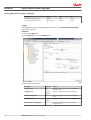
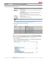
1. Open the WSxxx_DanfossDefault.DOD configuration file
2. Right-click on the top entry in the tree structure to open the context menu.
3. In the context menu, click on New Object Dictionary Group > Custom CAN Communication.
This creates the object dictionary group Custom CAN Communication.
4. Right-click on the object dictionary group Custom CAN Communication.
5. In the context menu, click on New Object Dictionary Group > Recieve CAN Messages (PDOs).
This creates the object dictionary group Receive CAN Messages (PDOs).
6. Right-click on the object dictionary group Recieve CAN Messages (PDOs).
6
BC00000348 en-US • Rev 0100 • October 2015
User Manual
Danfoss Telematics Solution Logging Data
Creating object dictionary groups and objects
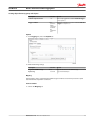
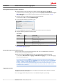
7. In the context menu, click on New Object Dictionary Entry > Recieve Message PDO.
This opens the window Number of new Objects and their Version.
8. Under Number of new Objects, enter the number of objects (received messages) you want to create.
In this example: 1.
9. Click on the OK button.
The object Receive Message PDO is created.
Rename entry
Rename an entry in the tree structure;
1. Click on the corresponding entry to select it.
2. Click on the entry again to rename it.
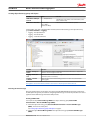
Modifying the logging configuration
In logging mode, the device logs CAN messages, GNSS data, and internal variables. All logged data is
saved to an internal, nonvolatile memory and sent to the DTS portal.
Alternatively, you can also save the data to an inserted microSD memory card. You can read off the data
saved on the microSD memory card using the USB interface.
The internal nonvolatile memory has a capacity of 32 MB and can save a maximum of 5000 files.
When the memory is full, each new file saved is overwritten over the oldest file. Here you will find an
explanation of how to configure the device, using some concrete examples.
You must define basic variables in order to correctly link up the device with an existing CAN network.
Configuring the device for Data Logging
BC00000348 en-US • Rev 0100 • October 2015
7
User Manual
Danfoss Telematics Solution Logging Data
Creating object dictionary groups and objects
1. In the object dictionary group Device Variables, click on the variable Device Application MasterMode.
2. Enter the value 0 to enable Data Logging/File Transfer Mode.
Logging CAN messages and sending them to DTS portal
You must configure at least the following variables to enable CAN communication (the variables belong
to the object dictionary group Device Variables > CAN Basic Settings):
• CANopen NMT Startup
• CAN1 Device CANopen Node ID
• CAN1 Device Baud Rate
• CAN2 Device CANopen Node ID
• CAN2 Device Baud Rate
8
Variable
Value
Function
CANopen NMT Startup
0
Automatically sets the device to CANopen mode
Operational.
CAN1: Device CANopen
Node ID
1 … 127 (default 37)
The CANopen node address / device ID number (can be
left at standard value).
CAN1: Device Baud Rate
min. 50 kbit/s
max. 1 Mbit/s
(default: 250 kBit/s)
The bit rate at which the CAN bus operates
BC00000348 en-US • Rev 0100 • October 2015
User Manual
Danfoss Telematics Solution Logging Data
Creating object dictionary groups and objects
Variable
Value
Function
CAN2: Device CANopen
Node ID
1 … 127 (default 37)
The CANopen node address / device ID number (can be
left at standard value).
CAN2: Device Baud Rate
min. 50 kbit/s
max. 1 Mbit/s
(default: 250 kBit/s)
The bit rate at which the CAN bus operates
For the logfiles, you must configure further variables (These variables belong to the object dictionary
group Device Variables > Logging):
• Logging – File Upload Period
• Logging – File Header Text
• Logging – Send File Command
Variable
Function
Logging – File Upload
Period
Period in which the logfile is completed and sent to the DTS Portal. 0 = data is sent
when the size of the logfile reaches 1 kB.
Logging – File Header
Text
Information text in the head of each logfile. Can contain for instance version
information (max. 32 characters).
Logging – Send File
Command
Assign any value to the variable during operation in order to close and send the
existing logfile.
The logfile is sent to the DTS Portal when its size reaches 1 kB, irrespective of the time set.
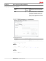
Receiving the J1939 message
Using the example of the receipt of the J1939 message (with PGN 61444 Electronic Engine Controller 1),
we will explain the general procedure for configuring CAN messages received. The procedure can also be
applied to other CAN messages from other CAN protocols.
Creating a PGN 61444
You require an object Receive Message PDO in the object dictionary group Custom CAN
Communication > Receive CAN Messages (PDOs).
1. Create the object dictionary group Custom CAN Communication > Receive CAN Messages
(PDOs) , if it does not already exist.
See Creating object dictionary groups and objects on page 6.
2. Create the object Recieve Message PDO in the object dictionary group Receive CAN Messages
(PDOs).
BC00000348 en-US • Rev 0100 • October 2015
9
User Manual
Danfoss Telematics Solution Logging Data
Creating object dictionary groups and objects
3. Rename the object.
In this example in PGN 61444.
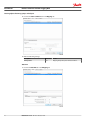
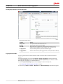
Receive Message Communication Parameters
1. Click on the Communication tab and make the following settings:
Description
Selection
Result
CAN Protocol
None
The receive CAN message is a single message (Layer 2).
Valid on CAN Interface
Set
Activates the configuration, sets the reception channel
(if several are available).
2. Click on the Standard Channel tab in the Communication tab and make the following settings:
10
Description
Selection
Result
Full CAN Message Object
Set
Assigns the receive message to a controller channel.
ID-Length
29-bit ID
ID length of the CAN message to be received.
DOWN-SAMPLE
Set (100)
Receive message max. every 100 ms (not every 10ms as
transmitted)
BC00000348 en-US • Rev 0100 • October 2015
User Manual
Danfoss Telematics Solution Logging Data
Creating object dictionary groups and objects
Description
Selection
Result
Cob-ID
Fix
(00F00400)
Fixed identifier of the receive message (J1939 PGN
61444).
Mask
Fix
(00FFFF00)
This mask determines that bits 8 … 24 of the identifier
fixed in Cob-ID must not vary in the identifier of the
receive message. In the J1939 protocol, this is the PGN
area. The first bits of the identifier define the priority
and the last bits of the identifier define the source
address. That is why these bits of the identifier in the
J1939 protocol can be different and are not evaluated
on reception in this example.
Timeout and Conditions
1. Click on the Timeout and conditions tab in the Communication tab
2. Make the following settings:
Description
Selection
Result
Always active
Set
The CAN message is received irrespective of events or
conditions.
Logging of all data bytes every 60 seconds
Example 1
Simple cyclical logging without checking additional conditions.
The example is based on the settings in the chapter Receiving the J1939 message on page 9.
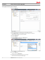
Logging
Conditions
1. Click on the Logging tab.
BC00000348 en-US • Rev 0100 • October 2015
11
User Manual
Danfoss Telematics Solution Logging Data
Creating object dictionary groups and objects
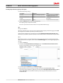
2. In the Logging tab, click on the Conditions tab.
3. Make the following settings
Description
Selection
Result
Logging enabled
Set
Logging enabled
Log message on
AND
The data is only logged when timeout is reached AND
the condition is met.
Logging period
Use a fix
value
(60000)
Duration of the logging interval in milliseconds.
Condition / Always true
Set
Logging takes place without prior checking of
conditions.
Payload
1. In the Logging tab, click on the Payload tab.
2. Make the following settings:
Description
Selection
Result
Log received CAN message
Set
Log the data of the receive CAN message.
Bytes to log
All
Log all data bytes.
3. Save the configuration file and load the configuration to the device as described in Configuring the
device for Data Logging on page 7.
12
BC00000348 en-US • Rev 0100 • October 2015
User Manual
Danfoss Telematics Solution Logging Data
Creating object dictionary groups and objects
Log specific bytes under certain conditions or every 10 minutes
Example 2
More complex logging based on the following conditions.
The example is based on the settings in the chapter Receiving the J1939 message on page 9.
Log bytes 2 to 5 and 8 of the receive message if the engine speed (byte 4 - 5) has changed by ± 500 rpm,
or every 10 minutes.
Variables
You need various variables for checking values if you want to log data only under certain conditions.
To set the corresponding variables, you need the object dictionary group Interface Variables.
1. Create the object dictionary group Interface Variables if it does not already exist.
See Creating object dictionary groups and objects on page 6.
2. Create 4 interface variables in the object dictionary group Interface Variables.
For each variable, the window List of Interface Variables opens.
3. Click on the variable you require.
4. Click on the OK button.
The selected variable is created.
5. Repeat the process for each variable.
6. Rename the variables in a useful way.
You need the following variables for the value checks.
Description
Type
Sign
Size
volatile U8 Trigger
volatile
unsigned
8 bits
volatile S32 Engine Speed new
volatile
signed
32 bits
BC00000348 en-US • Rev 0100 • October 2015
13
User Manual
Danfoss Telematics Solution Logging Data
Creating object dictionary groups and objects
Description
Type
Sign
Size
volatile S32 Engine Speed old
volatile
signed
32 bits
non-volatile U16 threshold value
non-volatile
unsigned
16 bits
Logging
Enter the following settings in the PGN 61444 object dictionary in the Custom CAN Communication
object dictionary group.
Conditions
1. Click on the Logging tab.
2. In the Logging tab, click on the Conditions tab.
3. Make the following settings:
14
Description
Selection
Result
Log message on
OR
The data is logged when timeout is reached OR the
condition is met.
Logging period
Fix value
(600000)
Duration of the logging interval in milliseconds.
Condition / Always true
not set
The data is logged irrespective of the result of the
check.
Comparison value
volatile U8
Trigger
Logging depends on the volatile U8 Trigger variable.
Number of bits containing data
8
All 8 bits of the variable are compared with the
comparison value.
BC00000348 en-US • Rev 0100 • October 2015
User Manual
Danfoss Telematics Solution Logging Data
Creating object dictionary groups and objects
Description
Selection
Result
Active if comparison value
<>0
Data is only logged if the variable volatile U8 Trigger
is not equal to 0.
Trigger condition
This
operation
will be
carried out
each time
the
condition is
true
Logging is enabled as long as the variable volatile U8
Trigger is not equal to 0.
Payload
1. In the Logging tab, click on the Payload tab
2. Make the following settings:
Description
Selection
Result
Log received CAN message
Set
Log the data of the receive CAN message.
Bytes to log
2..5 and 8
Log selected data bytes.
Mapping
During mapping, data is copied from the CAN message to variables. You can then process the copied
data in the device and perform calculations.
Active Conditions
1. Click on the Mapping tab.
BC00000348 en-US • Rev 0100 • October 2015
15
User Manual
Danfoss Telematics Solution Logging Data
Creating object dictionary groups and objects
2. Click on the Active condition tab in the Mapping tab.
3. Make the following settings:
Description
Selection
Result
Always active
Set
Mapping always takes place without conditions.
Data Link
1. Click on the Data link tab in the Mapping tab.
16
BC00000348 en-US • Rev 0100 • October 2015
User Manual
Danfoss Telematics Solution Logging Data
Creating object dictionary groups and objects
2. Make the following settings:
Description
Selection
Result
Parameter
volatile S32 Engine Speed new
The data is written to the volatile
S32 Engine Speed new variable.
Data start bit within receive
message
24 bits
The data used starts with bit 24
(from byte 4).
Number of bits containing data
16 bits
The data used has 16 bits (2 bytes).
3. Click on the New button to create the mapping entry.
The mapping entry is adopted in the table.
The data is copied into the internal variable on receipt of the CAN message.
Jobs
Change to the Jobs tab.
Every time a CAN message is received, jobs are performed after mapping and before logging. In the Jobs
tab, configure the calculation operations you need for your job.
For the example configuration, you need two jobs of type Calculate Parameter Value Function. With
this function, you perform calculation operations and overwrite interface variables with calculated values.
Job 1
With the first job (Job 1), you check whether the current engine speed is above or below the threshold
value. If one of these cases applies, set the variable volatile U8 trigger to 1, which triggers logging of the
message.
1. Click on the Jobs tab.
2. In the list under Current function of selected job, click on Calculate Parameter Value Function.
The jobs already defined are listed in the adjacent field.
3. In the list adjacent to Result, click on volatile U8 trigger.
4. Using the buttons on the tab, enter the calculation operations (A < (B - C)) or (D > (E + F))
If you click on the placeholder (e.g. A), this opens the window Input Operand Information or open a
new "(" Operation. To find out which variables you must assign to the placeholders, see Table
Variables for Job1.
BC00000348 en-US • Rev 0100 • October 2015
17
User Manual
Danfoss Telematics Solution Logging Data
Creating object dictionary groups and objects
5. In the list, click on the variable you want to assign to the placeholder
(in the example, for A, the variable volatile S32 Engine Speed New).
6. Click on the button with the placeholder (e.g. A).
7. Click on the New button when you have entered the calculation operations completely.
The buttons for entering the calculation operations have the following functions:
Buttons
Description
C = Clear: Deletes the entire calculation operation
CE = Clear Entry: Only deletes the last symbol entered
Add variables to the calculation operation.
Click on the button to open a window. Assign fixed values, interface variables, or device
variables to the variables. After you have defined a variable, the display on the button
jumps to the next variable.
The selected variables are listed under List of operands, including their values and types.
Basic calculation types (addition, subtraction, multiplication, division)
18
BC00000348 en-US • Rev 0100 • October 2015
User Manual
Danfoss Telematics Solution Logging Data
Creating object dictionary groups and objects
Buttons
Description
and = logical AND link
If all linked operands are true or not equal to zero, the result is Operation 1. Otherwise,
the result is Operation 0.
or = logical OR link
If one of the linked operands is true or not equal to zero, the result is Operation 1.
Otherwise, the result is Operation 0.
If both linked variables are full-number values (integers), the link is made by bits.
Comparison signs (equal to, smaller than, greater than, not equal to, smaller or equal to,
and larger or equal to)
The result is 1 when the comparison is true.
The result is 0 when the comparison is not true.
Brackets
The calculation formulas are evaluated from left to right. Mathematical priority rules are not
observed. Define the priority calculations in the formula using brackets.
8. Assign the following variables to the placeholders.
Job 1 variable
Variable
Type
Name/Value
A
S32
volatile S32 Engine Speed new
B
S32
volatile S32 Engine Speed old
C
U16
non-volatile U16 threshold value
D
S32
volatile S32 Engine Speed new
E
S32
volatile S32 Engine Speed old
F
U16
non-volatile U16 threshold value
Job 2
With the second job (Job 2), you replace the value of the variable volatile S32 Engine Speed Old with
the value of the variable volatile S32 Engine Speed New as soon as the variable volatile U8 Trigger has
the value 1. This updates the speed from which the deviation should be detected.
1. Click on the Jobs tab.
2. In the list under Current function of selected job, click on Calculate Parameter Value Function.
The jobs already defined are listed in the adjacent field.
3. In the list adjacent to Result, click on volatile S32 Engine Speed Old.
BC00000348 en-US • Rev 0100 • October 2015
19
User Manual
Danfoss Telematics Solution Logging Data
Creating object dictionary groups and objects
4. Using the buttons on the tab, enter the calculation operations ((A <> B) * C) + ((D – E) * F).
If you click on the placeholder (e.g. A), this opens the window Input Operand Information or open a
new "(" Operation. To find out which variables you must assign to the placeholders, see Job 2
variable on page 20.
5. In the list, click on the variable you want to assign to the placeholder
(in the example, for A, the variable volatile U8 Trigger).
6. Click on the button with the placeholder (e.g. A).
7. Click on the New button when you have entered the calculation operations completely.
8. Assign the following variables to the placeholders.
Job 2 variable
Variable
Type
Name/Value
A
U8
volatile U8 Trigger
B
fix
0
C
S32
volatile S32 Engine Speed new
D
U8
volatile U8 Trigger
E
fix
0
F
S32
volatile S32 Engine Speed old
9. Save the configuration file and load the configuration to the device as described in Configuring the
device for Data Logging on page 7.
Saving CAN messages to microSD memory cards
You can save the data to an inserted microSD memory card. You can read off the data saved on the
microSD memory card using the USB interface.
The data (.cls) is saved in the LOG directory. For this, a microSD memory card must be inserted.
Set the variable Device Variable > Logging > Enable SD Card Logging to 1, to enable data logging
to the microSD memory card.
Do not delete data from the Logging directory. This could cause problems with sending to DTS
server. However, you can delete the entire Logging directory with all the data. If the variable Device
Variable > Logging > Enable SD Card Logging is set to 0 or no microSD memory card is inserted,
the data is saved to the internal nonvolatile memory. The internal nonvolatile memory has a capacity
of 32 MB and can save a maximum of 5000 files. When the memory is full, each new file saved is
overwritten over the oldest file.
Logging GNSS positions
The GNSS position data contains information on longitude and latitude, altitude, direction, and speed
over ground as well as time and date.
Data is only logged when valid position data is received (GNSS LED lights up constantly).
20
BC00000348 en-US • Rev 0100 • October 2015
User Manual
Danfoss Telematics Solution Logging Data
Creating object dictionary groups and objects
Make the following settings:
Variable
Function
Once per file
Each logfile contains position data at least once.
Enabled
Enables/ disables the position data logging.
AND / OR
AND: Position data is logged if both conditions (time and distance) are met.
OR: Position data is logged if one of the conditions (time or distance) is met.
Logging period
Time period during which the position data should be logged.
Logging distance
Distance between the last position logged and the current position (linear distance).
Logging internal variables
You can log various internal variables. Internal variables can be both device variables and interface
variables.
To log internal variables, you need an object Action - Function - Operation in the object dictionary
group Operation Manager. With the object Action - Function - Operation, up to 8 internal variables
can be logged in one process as a virtual CAN message.
1. Create an Operation Manager object dictionary group if it does not already exist.
See Creating object dictionary groups and objects on page 6.
2. Create an object Action - Function - Operation in the Operation Manager object dictionary group.
BC00000348 en-US • Rev 0100 • October 2015
21
User Manual
Danfoss Telematics Solution Logging Data
Creating object dictionary groups and objects
3. Click on the Basic tab.
4. Select a time period (in ms) during which you want logging to take place.
5. Enable Always active if you want logging to take place irrespective of conditions.
Alternatively, you can define conditions for logging.
6. Click on the Save button.
7. Click on the Jobs tab.
8. Click on the Add button adjacent to the Overview field.
The Create new job window opens.
9. Select Logging in the Create new job window.
10. Click on the OK button.
The job is added to the Overview list.
11. Enter the ID for the virtual CAN message in the Cob-ID field.
The ID must not be used by other CAN messages.
22
BC00000348 en-US • Rev 0100 • October 2015
User Manual
Danfoss Telematics Solution Logging Data
Creating object dictionary groups and objects
12. Select the variable type and the variable in the field ADD NEW ROW.
13. Click on the Add button next to the field Add new row.
The selected variable is added to the list.
14. Add more variables to the list as required.
15. Save the settings.
BC00000348 en-US • Rev 0100 • October 2015
23
User Manual
Danfoss Telematics Solution Logging Data
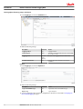
Configure Logged Data View
As a Danfoss Telematics Solutions customer using the WS403, on your DTS portal account you have the
possibility to show some of the logging data direct on the portal.
Data view
If the selected machine shows on the right side of the machine overview a highlighted symbol
it is possible to see all or a collection of the latest logging data direct on the portal screen.
A mouse click on the symbol will show the configured selection of the logging data.
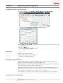
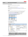
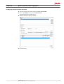
Adapt the configuration to the web portal
The display of the logging data needs a configuration via a xml script. This script must be downloaded to
portal via Administration > Machine Configuration.
Select the Add Machine Configuration option to open the file selection menu
The selected xml-file will be tested of consistence after pressing the load button. If any error is detected
inside the xml-file, the system will reject the file with an error message pointing to the first error position.
24
BC00000348 en-US • Rev 0100 • October 2015
User Manual
Danfoss Telematics Solution Logging Data
Configure Logged Data View
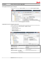
After system accept the configuration it is possible to select a number of machines that are able to use
this configuration.
Please take care the also the dod-file of the selected machines have the same logging configuration to
support the needed logging data.
Don’t forget to press the Save button to activate this script on the portal.
Elements of the xml file
To support the structure of an xml file it much easier to use an editor that support these structures.
One option it to use the freeware https://notepad-plus-plus.org/ plus xml support http://sourceforge.net/
projects/notepad-plus/#add-ons-plugins.
To identify the xml configuration we need a UUID. There are some creators for ID’s available on the
internet like https://www.uuidgenerator.net .
XML Header
The header has fixed and variable values. All values are fixed like in the sample below except the uuid,
the customerVersion and the keyPrefix.
For each xml file we need a unique identification ID uuid. To implement a change it is needed to
increment the customerVersion. The keyPrefix shows a short description about this script but is not
used internally. This prefix must be present to fulfill the rules of the scheme.
Message definition
The next parts of the header are some message definition to generate a message on the portal to make
an identification of the script easier. Both messages will be descripted in all available languages to take
BC00000348 en-US • Rev 0100 • October 2015
25
User Manual
Danfoss Telematics Solution Logging Data
Configure Logged Data View
care that the correct language will displayed regarding the user preference of the user profile. If only one
language is defined this label will be used independent of the user preference.
Global dictionary
Inside the global directory all used message are defined this section will be used at the definition of the
show value. All needed information on the web portal must defined in this section. This included the
name of the used tab of the views, the signal name and the unit name. Also in this message definition it is
possible to define in all supported languages. The message is identified by the key value.
Transformer
The transformer section will define calculation to change transferred binary information in physical units.
The transformer includes a key value to identify the transformer. The formula identifies the type of the
calculation. Actual only the "LinearFormula" is available as formula. The scale value will be multiplied with
the raw data value and additional the offset will be added to create a physical value from the CAN bus
raw data.
Units
Include-tag loads description of pre-defined units.
<xi:include href="http://xml.proemion.com/ProemionDataConfiguration/
predefinedUnits.xml" parse="xml" xpointer="element(/1)"/>
These units can be converted automatically according to the user‘s Preferences settings in the Portal
(Metric / US).
The following predefined units are available when using the include :
< VELOCITY >
predefined.unit.velocity.METERS_PER_SECOND
predefined.unit.velocity.FOOT_PER_SECOND
< FLOW RATE >
predefined.unit.flow.LITER_PER_HOUR
predefined.unit.flow.GALLON_LIQUID_US_PER_HOUR
< FORCE >
predefined.unit.force.NEWTON
predefined.unit.force.POUND_FORCE
26
BC00000348 en-US • Rev 0100 • October 2015
User Manual
Danfoss Telematics Solution Logging Data
Configure Logged Data View
< LENGTH >
predefined.unit.length.KILOMETER
predefined.unit.length.MILE
predefined.unit.length.METER
predefined.unit.length.FOOT
predefined.unit.length.MILLIMETER
predefined.unit.length.INCH
< MASS >
predefined.unit.mass.KILOGRAM
predefined.unit.mass.POUND
< PRESSURE >
predefined.unit.pressure.KILOPASCAL
predefined.unit.pressure.PSI
predefined.unit.pressure.BAR
predefined.unit.pressure.opt.PSI
< TEMPERATUR >
predefined.unit.temperature.CELSIUS
predefined.unit.temperature.FAHRENHEIT
< SPEED >
predefined.unit.speed.KILOMETERS_PER_HOUR
predefined.unit.speed.MILES_PER_HOUR
predefined.unit.speed.METERS_PER_SECOND
predefined.unit.speed.FOOT_PER_SECOND
< VOLUME >
predefined.unit.volume.LITER
predefined.unit.volume.GALLON_LIQUID_US
Custom units can be defined inside the section Units.
Symbol identifies the symbol or numeric value of the unit. Description is actual not used but must be
present to fulfill the rules of the scheme.
Available store types:
NumericValueStoreType
TextValueStoreType
BooleanValueStoreType
•
•
•
Value definitions
This entry combines a value label and a value unit to the defined value. This value is in any cases a
floating point value.
BC00000348 en-US • Rev 0100 • October 2015
27
User Manual
Danfoss Telematics Solution Logging Data
Configure Logged Data View
Parsing definition
This parsing information needs to synchronize the needed data for this portal display with the
configuration of the remote logging data transmit device. Actual only the CAN data are available for the
BinaryStreamDefinition. The message will be defined via the CAN-ID with the corresponding ID-Type and
Mask. The actual version support only the GENERIC protocol is supported.
CAN Message examples
Short identifier 11 bit
Long identifier 21 bit
canId
“0x123”
"0x18FF5003"
canIdLength
“11”
“29”
mask
“0x7FF”
"0x1FFFFFFF"
For every used value of a CAN message a value section must be defined.
Possible values can be:
• IntValue
• FloatValue
• SimpleCharValue
• SeparatedCharValue
To separate the value from a CAN stream (8byte = 64 bits) for each value can be defined a start bit and a
length of the value. For values bigger than one byte the correct byte order must be selected options are:
• endianness =”LITTLE” -> LSB first
• endianness =”BIG” -> MSB first
For the presentation of the values the system must know if the value shall be showen as signed or
unsigned. The selction here is:
• signed = “true”
• signed = “false”
The entry continueOnLastPosition needs to be always false.
The ValueDefinition is reverencing to the previously defined value.
The Transformer is referencing a calculation for the collected value. The Transformer is optional and only
needed if the raw data will not represent the actual numeric value.
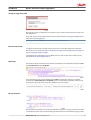
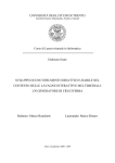
Extracting bits and multiple of bits from a virtual CAN message
To rebuild status information based on bits and multiple bits below 8 the system needs a mirrored
notation of the bit position in the frame, shifted by the length of the information (See Count in standard
order (orange) and mirrored order (yellow) on page 29)
28
BC00000348 en-US • Rev 0100 • October 2015
User Manual
Danfoss Telematics Solution Logging Data
Configure Logged Data View
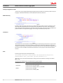
Count in standard order (orange) and mirrored order (yellow)
30 31 16 17 18 19 20 21 22 23 8 9 10 11 12 13 14 15
X X X X X X X X
X X X X
25 24 23 22 21 20 19 18 17 16 15 14 13 12 11 10 9 8
…
Byte 2
Byte 1
0
X
7
1
X
6
2
X
5
3 4
X X
4 3
Byte 0
5
X
2
6
X
1
7
X
0
P301 878.A
Example: J1939 Vehicle Fluids PGN 65128 (0x00FE68)
Position
0
1..0
1..2
2
Length
1 byte
2 bits
2 bits
1 byte
Parameter name
Hydraulic temperature
Hydraulic oil filter restriction switch
Winch oil pressure switch
Hydraulic oil level
SPN
1638
1713
1857
2602
P301 879.A
To get this information from a logged CAM message, it needs to be a setup like follow:
<CanMessage canId="0x18FE6800" canIdLength="29" mask="0x1FFFFFFF" protocolStyle="GENERIC">
<Values>
<IntValue startPos="0" length="8" endianness="LITTLE" signed="false" continueOnLastPosti on="false">
<valueDefinition ref="value.hydraulic.temp" />
</IntValue>
<IntValue startPos="14" length="2" endianness="LITTLE" signed="false" continueOnLastPosti on="false">
<valueDefinition ref="value.hydraulic.oilfilter.restrict.switch" />
</IntValue>
<IntValue startPos="12" length="2" endianness="LITTLE" signed="false" continueOnLastPosti on="false">
<valueDefinition ref="value.hydraulic.oil.press.switch" />
</IntValue>
<IntValue startPos="16" length="8" endianness="LITTLE" signed="false" continueOnLastPosti on="false">
<valueDefinition ref="value.hydraulic.oil.level" />
</IntValue>
</Values>
</CanMessage>
P301 880.A
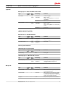
View definition
Each ViewDefinition is displayed as one tab on the portal. Actual there are the following types are
available:
• SimpleTableViewDefinition
• CustomTableViewDefinition
• DataHistoryTableViewDefinition
• ErrorTableViewDefinition
The title is displayed in the tab header.
BC00000348 en-US • Rev 0100 • October 2015
29
User Manual
Danfoss Telematics Solution Logging Data
Configure Logged Data View
The ValueView reverence to defined Value Definitions. Additional information in this row are related to
show a unit or not and to format a value in C-type configuration (only f = float are allowed). Also a
conditional analysis of a value is possible.
Simple and custom table are tables to show a bunch of actual data. The error and history view are useful
for event data like error flags. This kind of message can be shown with status flag value and time of
appear.
Inside a Value View the name of the value and the appearance of this entry will be defined. Additional to
the numeric value view a conditional option can show text and hints based on a numerical value. A
condition has one default section and one or more case sections. As selection for the cases the following
options are available:
• LessThan
• Equals
• GreatherThan
Inside a valid case section the following actions can be done:
replaceValue
setTextFormat
•
•
With the text format option several of standard options can be used:
bold
italic
underline
color
backgroundColor
•
•
•
•
•
The color definition is a 24 bit hexadecimal value with a byte for red, green and blue part.
• #RRGGBB
• #FF0000 -> color red
• #00FF00 -> color green
• #0000FF -> color blue
• #000000 -> color black
• #FFFFFF -> color white
In the custom view table it is possible to create a table of values in rows and columns. A headline and a
row description are also possible. The unit is a constituent part of the value and shown direct behind the
value in the same window. If a unit is not needed a empty Unit is to define for the value definition.
30
BC00000348 en-US • Rev 0100 • October 2015
User Manual
Danfoss Telematics Solution Logging Data
Configure Logged Data View
BC00000348 en-US • Rev 0100 • October 2015
31
User Manual
Danfoss Telematics Solution Logging Data
Appendix
CLF file
File header
Type
Length
[bytes]
Byte
Order
Value/Range
Comment
Start byte
1
*
0x55
STX (Start of TeXt): Marks the beginning of a
datagram
File format version
2
Big
Endian
0x0000..0xFFFF
Version indicating the file format's version;
Current Version = 13.
Length Byte
2
Big
Endian
0x0000..0xFFFF
Length of data to follow (everything after
Encryption Byte, including all messages and
up to, but not including, the Checksum XOR,
Checksum ADD and Stop Bytes)
Encryption Byte
1
*
00
00 = data is not encrypted
01
01 = data is encrypted
Other
Reserved
1
*
0x00..0x20
Header String Length= 'n'. A value of '00'
indicates there are no Header String values to
follow. Note: valid header length is within
0-32 bytes (was 0-255 in version 12)
Header String Value 1 1
*
0x00..0xFF
First character or data byte of Header String
(ASCII) for the file. Typically a Vehicle
Identification Number (VIN)
Header String Value 2 1
*
0x00..0xFF
*
0x00..0xFF
Length of header
…
Header String Value
‘n’
1
File payload
Typical message definition
Type
Length
[bytes]
Byte
Order
Value/Range
Comment
Message Type
1
*
0-7
CAN Data
8 - 15
Statistic Data
16 - 31
GPS Data
32 - 63
I/O Data
64 - 127
RS-232 Data
128 - 192
Customer-Specific
Others
Reserved
00
No timestamp for this message
01
UNIX message timestamp
Others
Reserved
Timestamp type
32
1
*
Message Length
2
Big
Endian
0x0000..0xFFFF
The sum of bytes to follow for this message,
including Message Values (1-'n') and
Timestamp Values (1-'z').
Message Value 1
1
*
0x00..0xFF
Message's payload: bytes 1-'n'. Format
determined by Message Type and defined in
Section 2, “File Payload” [3].
Message Value 2
1
*
0x00..0xFF
BC00000348 en-US • Rev 0100 • October 2015
User Manual
Danfoss Telematics Solution Logging Data
Appendix
Type
Length
[bytes]
Byte
Order
Value/Range
Comment
…
1
*
0x00..0xFF
Message Value ‘n’
1
*
0x00..0xFF
Last byte of Message Payload
Timestamp Value 1
1
*
0x00..0xFF
Timestamp Payload: bytes 1-'z', if Timestamp.
Type is nonzero. Format determined by
Timestamp Type as defined in Section 3,
“Message Tail” [11].
Timestamp Value 2
1
*
0x00..0xFF
1
*
0x00..0xFF
…
…
Timestamp Value ‘z’
Last byte of Timestamp payload
Repeat the above sequence for all subsequent messages in file. See Section 2, “File Payload” [3] above
Message Payload Definitions
Message Type 0 = 11-bit CAN Message
Type
Length
[bytes]
Byte
Order
Value/Range
Comment
Message Value 1: Bitmask
1
*
0x00..0xFF
8 bits, each bit representing, respectively,
which of the 8 Data Bytes (1-'n') of the
original 11-bit message are included.
Message Header
2
Big
Endian
0x000..0x7FF
11-bit CAN message ID
Data Byte Value 1
1
*
0x00..0xFF
First byte of up to 8 Data Bytes in the original
11-bit message
Data Byte Value 2
1
*
0x00..0xFF
Second byte of up to 8 Data Bytes in the
original 11-bit message
1
*
0x00..0xFF
Last byte of up to 8 Data Bytes in the original
11-bit message
…
Data Byte Value ‘n’
Message Type 1 = 29-bit CAN Message
Type
Length
[bytes]
Byte
Order
Value/Range
Comment
Message Value 1: Bitmask
1
*
0x00..0xFF
8 bits, each bit representing, respectively,
which of the 8 Data Bytes (1-'n') of the original
29-bit message are included. If Bitmask = '00',
the message length can be equal to 0x8 and
up to 0x6F9.
Message Header
4
Big
Endian
0x0000 0000..
0x7FFF FFFF
11-bit CAN message ID
Data Byte Value 1
1
*
0x00..0xFF
First byte of up to 8 Data Bytes in the original
29-bit message
Data Byte Value 2
1
*
0x00..0xFF
Second byte of up to 8 Data Bytes in the
original 29-bit message
1
*
0x00..0xFF
Last byte of up to 8 Data Bytes in the original
29-bit message
…
Data Byte Value ‘n’
Message Type 2 = 11-bit CAN Message with source
Version 14+
BC00000348 en-US • Rev 0100 • October 2015
33
User Manual
Danfoss Telematics Solution Logging Data
Appendix
Type
Length
[bytes]
Byte
Order
Value/Range
Comment
Message Value 1:
Source Bus
1
*
0x01..0xFF
Some of our logging hardware has more than
one CAN interface. This value represents the
physical CAN bus from which the message
originated.
Bit-mask
1
*
0x00..0xFF
8 bits, each bit representing, respectively,
which of the 8 data bytes (1-'n') of the
original 11-bit message are included.
Message Header
2
Big
Endian
0x000..0x7FF
11-bit CAN message ID
CAN Data Length
1
Code introduced with
V.15
*
0x00..0xFF
CAN DLC - necessary to work with bitmask
Data Byte Value 1
1
*
0x00..0xFF
First byte of up to 8 Data Bytes in the original
11-bit message
Data Byte Value 2
1
*
0x00..0xFF
Second byte of up to 8 Data Bytes in the
original 11-bit message
1
*
0x00..0xFF
Last byte of up to 8 Data Bytes in the original
11-bit message
…
Data Byte Value ‘n’
Message Type 3 = 29-bit CAN Message with source
Version 14+
Type
Length
[bytes]
Byte
Order
Value/Range
Comment
Message Value 1:
Source Bus
1
*
0x01..0xFF
Some of our logging hardware has more than
one CAN interface. This value represents the
physical CAN bus from which the message
originated.
Bit-mask
1
*
0x00..0xFF
8 bits, each bit representing, respectively,
which of the 8 data bytes (1-'n') of the
original 29-bit message are included. If
bitmask = '00', the message length can be
equal to 0x8 and up to 0x6F9.
Message Header
4
Big
Endian
0x0000 0000..0x7FFF
FFFF
29-bit CAN message ID
CAN Data Length
1
Code introduced with
V.15
*
0x00..0xFF
CAN DLC - necessary to work with bitmask
Data Byte Value 1
1
*
0x00..0xFF
First byte of up to 8 Data Bytes in the original
29-bit message
Data Byte Value 2
1
*
0x00..0xFF
Second byte of up to 8 Data Bytes in the
original 29-bit message
1
*
0x00..0xFF
Last byte of up to 8 Data Bytes in the original
29-bit message
…
Data Byte Value ‘n’
34
BC00000348 en-US • Rev 0100 • October 2015
User Manual
Danfoss Telematics Solution Logging Data
Appendix
Message Type 16 = GPS Location Data (J1939 format)
Type
Length
[bytes]
Byte
Order
Value/Range
Comment
GPS Latitude
4
Little
Endian
0x00000000..
0xFAFEE27A
Scalar: 10-7 deg/bit
Offset: -210 deg
Range: -210 deg (SOUTH)a to +211.108122
deg (NORTH)
0xFFFFFFFF
Invalid Data
0x00000000..
0xFAFEE27A
Scalar: 10-7 deg/bit
Offset: -210 deg
Range: -210 deg (WEST) to +211.108122 deg
(EAST)b
0xFFFFFFFF
Invalid Data
GPS Longitude
4
Little
Endian
a Reference from J1939-71 SPN 584
b Reference from J1939-71 SPN 585
Message Type 17 = GPS Movement Data
Type
Length
[bytes]
Byte
Order
Value/Range
Comment
Heading
4
Little
Endian
0x00000000..
0xFFFFFFFF
Signed 32-bit Int
Scaling: 1e-5 Degrees
Ground Speed (2-D)
4
Little
Endian
0x00000000..
0xFFFFFFFF
cm/second
Timestamp Value Definitions
Timestamp Type 00 = No Timestamp
Type
Length
[bits]
Byte
Order
Value/Range
Comment
No timestamp
0
*
Null
Zero length.
Timestamp Type 01 = UNIX Timestamp (seconds)
Type
Length
[bits]
Byte
Order
Value/Range
Comment
UNIX timestamp
4
Big
Endian
0x00000000..
0xFFFFFFFF
Timestamp for each message (32 bit positive
or negative number of seconds since
midnight on January 1, 1970).
Type
Length
[bits]
Byte
Order
Value/Range
Comment
Checksum XOR
1
*
0x00..0xFF
XOR checksum over encryption byte (offset 5)
and all subsequent bytes.
Checksum ADD
1
*
0x00..0xFF
ADD checksum over encryption byte (offset
5) and all subsequent bytes including XOR
checksum bytes. All bytes will be summed up
and the carry over will be discarded.
Stop Byte
1
*
0xAA
ETX (End of Text): Marks the end of the file
Message tail
BC00000348 en-US • Rev 0100 • October 2015
35
User Manual
Danfoss Telematics Solution Logging Data
Appendix
Bitmask
Empty or irrelevant bytes of CAN messages can be omitted by defining a proper bitmask. A set bit marks
a transmitted byte, an unset bit a omitted bytes.
The bits are interpreted in order of their significance (Bitmask: MSB 8 7 6 5 4 3 2 1 LSB, Message Bytes: 01
02 03 04 05 06 07 08 ).
A bitmask of 0x04 defines, that only the 3rd byte of the can message is transferred.
When using bitmasks, the can messages can't be longer than 8 bytes. If all bit are either unset (0x00) or
set (0xFF) the message is transferred completely and, if the message type supports it, can be longer than
8 bytes.
Examples
Example 1
The first example explains the order in which file section will occur.
The second example will demonstrate what the data byte will look like in the file format.
Section 1, “File Header” [3]
File Header - The file header will always start the file structure.
This contains Start Byte, File Format Version, Length Bytes, Encryption Byte and the File Header.
Section 2, “File Payload” [3]
Message Header - The section describes the Message Type that is to follow, the Timestamp Type that is to
follow and the Message Length, which is the length of the Message Values and Timestamp Values.
Message Payload - This is unique to each Message Type. The length of this section is defined by Message
Length in the Message Header.
The meaning of the data bytes is detailed in the following sections.
Message Type 0 - 11 bit CAN Message - Node 1
Each 11 bit CAN message consists of a Bitmask, Message Header and up to 8 Data Bytes. The user has the
ability to remove irrelevant or undefined payload bytes from the original 11-bit CAN message using the
Bitmask. The Bitmask allows the message to retain the position of the bytes in the message when
irrelevant bytes are removed from the message. The 11 bit Message Header is the CAN ID of the 11 bit
message.
The meaning of the 11 bit Message Value is user defined.
Message Type 1 - 29 bit CAN Message - Node 1
Each 29 bit CAN message consists of a Bitmask, Message Header and up to 1,785 Data Bytes. The user has
the ability to remove irrelevant or undefined payload bytes from the original 29-bit CAN message using
the Bitmask. The Bitmask allows the message to retain the position of the bytes in the message when
irrelevant bytes are removed from the message. If the Bitmask is 00, then the 29 Bit Message Values can
be greater than or equal to 8 bytes but less than or equal to 1,785. The 29 bit Message Header is the CAN
ID of the 29 bit message.
29 bit Message Values that have a length longer than 8 are often created using J1939 multicast BAM
message.
Please reference J1939-21. The meaning of the 29 bit Message Value is user defined.
36
BC00000348 en-US • Rev 0100 • October 2015
User Manual
Danfoss Telematics Solution Logging Data
Appendix
Message Type 2 - 11 bit CAN Message - Node 2
Exactly the same as type 0, but the message originates from the second CAN node of the micro controller.
This is a physically separate CAN bus.
Message Type 3 - 29 bit CAN Message - Node 2
Exactly the same as type 1, but the message originates from the second CAN node of the micro controller.
This is a physically separate CAN bus.
Message Type 16 - GPS Location Data (J1939 Format)
The GPS Data message is a fixed length of 8 bytes. The first 4 bytes are GPS Latitude coordinate and the
second 4 bytes are the GPS Longitude coordinate. The binary value is an unsigned 32 bit.
To decode the meaning of this binary value, convert to decimal; apply the scalar of 107 and the offset of
-210 (decimal).
This method of conversion is valid for both GPS Latitude and Longitude.
If the Value is 'FFFFFFFF' then the GPS data is invalid.
Message Type 17 - GPS Movement Data (J1939 Format)
This message contains the heading and speed data of the device. The heading is encoded as a four-byte
signed integer. The scaling is 1e-5 degrees. The speed is a four byte unsigned integer representing
centimeters per second.
Timestamp Type 00 = No Time Stamp
No Time Stamp has a length of zero. Thus, there is no timestamp in this message.
Timestamp Type 01 = UNIX Time Stamp
The UNIX Time Stamp has a length of 4 bytes. The 32 bit signed binary number can be converted.
This is a count of the number of seconds that have passed since January 1st, 1970.
Section 3, “Message Tail” [11]
Checksum XOR - The XOR of all bytes from the encryption byte to all bytes up to but no including the
Checksum XOR byte.
Checksum ADD - The SUM off all bytes from the encryption byte to all bytes up to, but not including, the
Checksum ADD byte.
Stop Byte. - Marks the end of the binary file. (ETX)
Example 2
Let us have a look at the following example:
Line 1:
55 00 0C 00 37 00 05 56 49 4E 20 31
Line 2:
00 00 00 05 0C 02 3A FF AA
Line 3:
41 01 00 0B 01 02 03 04 05 06 07 47 79 F3 00
Line 4:
08 00 00 04 00 19 00 05
Line 5:
21 01 00 08 0A 62 00 64 47 79 F3 01
Line 6:
22 00 00 01 4A
Line 7:
4A 44 AA
BC00000348 en-US • Rev 0100 • October 2015
37
User Manual
Danfoss Telematics Solution Logging Data
Appendix
The above binary file contains the following information
Line 1 - File Header:
‒ Version: 12
‒ Header: VIN 1
‒ Length: 55
‒ Data is not encrypted
• Line 2 - 11 bit CAN Message:
‒ CAN Message ID: 570
‒ Message Values: 00 00 00 00 FF AA 00 00
‒ No Timestamp
• Line 3 - RS232 String:
‒ RS232 Values: 01 02 03 04 05 06 07
‒ Timestamp: January 1st, 2008, 08:00:00
• Line 4 - Statistics String:
‒ On/Off Counter: 25
‒ GSM Registration Counter: 5
‒ No Timestamp
• Line 5 - Analog Input:
‒ Value 1: 2658
‒ Value 2: 100
‒ Timestamp: January 1st, 2008, 08:00:01
• Line 6 - Digital Output:
‒ Value 1: High
‒ Value 2: Low
‒ Other: Not Present
‒ No Timestamp
• Line 7 - Checksum XOR:
‒ Checksum and Stop Byte
•
38
BC00000348 en-US • Rev 0100 • October 2015
User Manual
Danfoss Telematics Solution Logging Data
BC00000348 en-US • Rev 0100 • October 2015
39
Products we offer:
•
•
•
•
•
•
•
•
•
•
•
•
•
•
•
•
Bent Axis Motors
Closed Circuit Axial Piston
Pumps and Motors
Displays
Electrohydraulic Power
Steering
Electrohydraulics
Danfoss Power Solutions is a global manufacturer and supplier of high-quality hydraulic and
electronic components. We specialize in providing state-of-the-art technology and solutions
that excel in the harsh operating conditions of the mobile off-highway market. Building on
our extensive applications expertise, we work closely with our customers to ensure
exceptional performance for a broad range of off-highway vehicles.
We help OEMs around the world speed up system development, reduce costs and bring
vehicles to market faster.
Danfoss – Your Strongest Partner in Mobile Hydraulics.
Hydraulic Power Steering
Go to www.powersolutions.danfoss.com for further product information.
Integrated Systems
Wherever off-highway vehicles are at work, so is Danfoss. We offer expert worldwide support
for our customers, ensuring the best possible solutions for outstanding performance. And
with an extensive network of Global Service Partners, we also provide comprehensive global
service for all of our components.
Joysticks and Control
Handles
Microcontrollers and
Software
Open Circuit Axial Piston
Pumps
Orbital Motors
Please contact the Danfoss Power Solution representative nearest you.
PLUS+1® GUIDE
Proportional Valves
Sensors
Steering
Transit Mixer Drives
Comatrol
www.comatrol.com
Schwarzmüller-Inverter
www.schwarzmuellerinverter.com
Local address:
Turolla
www.turollaocg.com
Hydro-Gear
www.hydro-gear.com
Daikin-Sauer-Danfoss
www.daikin-sauer-danfoss.com
Danfoss
Power Solutions (US) Company
2800 East 13th Street
Ames, IA 50010, USA
Phone: +1 515 239 6000
Danfoss
Power Solutions GmbH & Co. OHG
Krokamp 35
D-24539 Neumünster, Germany
Phone: +49 4321 871 0
Danfoss
Power Solutions ApS
Nordborgvej 81
DK-6430 Nordborg, Denmark
Phone: +45 7488 2222
Danfoss
Power Solutions Trading
(Shanghai) Co., Ltd.
Building #22, No. 1000 Jin Hai Rd
Jin Qiao, Pudong New District
Shanghai, China 201206
Phone: +86 21 3418 5200
Danfoss can accept no responsibility for possible errors in catalogues, brochures and other printed material. Danfoss reserves the right to alter its products without notice. This also applies to
products already on order provided that such alterations can be made without changes being necessary in specifications already agreed.
All trademarks in this material are property of the respective companies. Danfoss and the Danfoss logotype are trademarks of Danfoss A/S. All rights reserved.
BC00000348 en-US • Rev 0100 • October 2015
www.danfoss.com
© Danfoss A/S, 2015