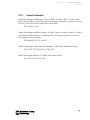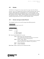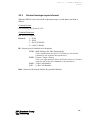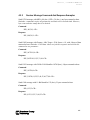
1
DEARBORN PROTOCOL ADAPTER DPA III /i USER’S MANUAL Version 2.06 Rev4 2002 Dearborn Group Inc. 27007 Hills Tech Court Farmington Hills, MI 48331 Phone (248) 488-2080 • Fax (248) 488-2082 http://www.dgtech.com i D P A I I I / i U S E R ’ S M A N U A L 2 0 0 4 This document is copyrighted by the Dearborn Group Inc. Permission is granted to copy any or all portions of this manual, provided that such copies are for use with the product provided by the Dearborn Group, and that the name “Dearborn Group Inc.” remain on all copies as on the original. IMPORTANT NOTICE The DPA III /i is intended for use as an evaluation tool only. Damage to the tool, if caused by misuse, is not covered under the seller’s product warranty. When using this manual, please remember the following: • This manual may be changed, in whole or in part, without notice. Current updates to this manual may be found on Dearborn Group’s web site at http://www.dgtech.com. • Dearborn Group Inc., does not assume responsibility for any damage resulting from any accident – or for any other reason – while the DPA III /i is in use. • Examples of circuitry described herein are for illustration purposes only and do not necessarily represent the latest revisions of hardware or software. Dearborn Group Inc. assumes no responsibility for any intellectual property claims that may result from use of this material. • No license is granted – by implication or otherwise – for any patents or any other rights of Dearborn Group Inc., or of any third party. DPA III /i is a trademark of Dearborn Group Inc. CAN is a trademark of Bosch Inc. Other products are trademarks of their respective manufacturers Manual revision history: June 2, 2004 May 14, 2003 TM (minor changes for consistency) (minor changes and clarification) ii D P A I I I / i U S E R ’ S M A N U A L 2 0 0 4 Table of Contents 1.0 1.1 1.2 1.3 2.0 Documentation organization..................................................................... 1 Technical support ......................................................................................... 2 Product Registration..................................................................................... 2 HOST INTERFACE.......................................................................... 3 2.1 Host Communication.................................................................................... 3 2.2 Host Connection ........................................................................................... 3 2.1.1 Quick Start ....................................................................................................................... 3 2.2.1 2.2.2 2.2.3 2.2.4 2.2.5 Host Communication Command..................................................................................... 5 Host Communication Initialization Command Format................................................... 6 Host Communication Command Examples .................................................................... 6 Save Serial Configuration Command .............................................................................. 7 Save Serial Configuration Command Examples.............................................................. 7 3.0 3.1 3.2 4.0 TM OVERVIEW .................................................................................. 1 PROTOCOL INTERFACE................................................................. 8 Supported Protocols..................................................................................... 8 Protocol Connections ................................................................................... 8 FUNCTIONALITY ........................................................................... 9 4.1 Protocol Initialization ................................................................................... 9 4.2 Transmit...................................................................................................... 13 4.3 Receive........................................................................................................ 15 4.4 Broadcast.................................................................................................... 18 4.5 Monitor....................................................................................................... 21 4.1.1 4.1.2 Protocol Initialization Command Format ....................................................................... 9 Protocols Initialization Examples: ................................................................................. 12 4.2.1 4.2.2 Transmit Command Format .......................................................................................... 13 Transmit Examples: ....................................................................................................... 14 4.3.1 4.3.2 4.3.3 Receive message command format .............................................................................. 15 Received message response format.............................................................................. 16 Receive Message Command And Response Examples.................................................. 17 4.4.1 4.4.2 4.4.3 4.4.4 Load Broadcast message command format ................................................................. 18 Broadcast Command Examples:.................................................................................... 19 Delete Broadcast Command Format............................................................................. 20 Delete Broadcast Command Examples ......................................................................... 20 4.5.1 4.5.2 4.5.3 4.5.4 4.5.5 4.5.6 4.5.7 Load Monitor Command Format .................................................................................. 21 Load Monitor Response Format.................................................................................... 22 Load Monitor Protocol Examples.................................................................................. 23 Read Monitor Command Format .................................................................................. 24 Read Monitor Protocol Examples.................................................................................. 25 Delete Monitor Command Format................................................................................ 26 Delete Monitor Examples .............................................................................................. 26 iii D P A I I I / i U S E R ’ S M A N U A L 2 0 0 4 4. 6 Buffer Commands .................................................................................... 27 4.7 Timer Commands ....................................................................................... 29 4.8 General Commands .................................................................................... 31 4.6.1 4.6.2 4.6.3 4.6.4 A. Read Buffer Command Format ..................................................................................... 27 Read Buffer Examples.................................................................................................... 27 Load Buffer Command Format ..................................................................................... 28 Load Buffer Command Examples.................................................................................. 28 4.7.1 4.7.2 4.7.3 4.7.4 Get Timer value command ............................................................................................ 29 Pause Timer command .................................................................................................. 30 Resume Timer command............................................................................................... 30 Set Timer command ...................................................................................................... 30 4.8.1 4.8.2 Get Version command................................................................................................... 31 Reset command............................................................................................................. 31 CAN BIT-TIMING REGISTERS....................................................... 32 INDEX .................................................................................................. 34 Table of Figures Figure 1 - DPA III /i to Host Wiring ............................................................................................... 4 Figure 2 – DPA III /i Bus Protocol Pinouts ..................................................................................... 4 Figure 3 – DPA III /i Bus Protocol Pinouts ..................................................................................... 8 TM iv D P A I I I / i U S E R ’ S M A N U A L 2 0 0 4 CHAPTER 1 1.0 Overview The DPA III /i is designed to support Programmable Logic Controllers (PLCs), Personal Computers (PCs) and Personal Digital Assistants (PDAs) where custom drivers are not always an option. Throughout this document these devices will be generically referred to as the Host. The DPA III /i is a custom version of our popular DPA, and is designed to understand ASCII commands. It uses a small set of ASCII commands to give the Host full access to all the protocols supported by the DPA III, without forcing the Host to take on the real time responsibility of the protocols themselves. 1.1 Documentation organization This manual contains several chapters, an appendix, and an index. Each chapter covers the following information. Chapter 1 – Overview - provides an overview of the manual and summarizes the contents of the remaining chapters and appendices. The remainder of this chapter provides reference to related documentation and technical support. The chapters that follow address these subjects: Chapter 2 – Host Interface - describes the steps necessary to use the DPA III /i. Chapter 3 – Protocol Interface - describes the protocols available and how to connect to them. Chapter 4 – Functionality – describes the commands used to communicate with the DPA III /i. TM 1 D P A 1.2 I I I / i U S E R ’ S M A N U A L 2 0 0 4 Technical support In the U.S., technical support representatives are available to answer your questions between 9 a.m. and 5 p.m. EST. You may also fax or e-mail your questions to us. Please include your voice telephone number, for prompt assistance. Non-U.S. users may want to contact their local representatives. Phone: Fax: E-mail: Web site: 1.3 (248) 488-2080 (248) 488-2082 [email protected] http://www.dgtech.com Product Registration Before getting started, please take a moment to log on to our web site to register this product online. As a registered user, you will receive technical support and important product upgrade information. http://www.dgtech.com/techsupp/tech.phtml TM 2 D P A I I I / i U S E R ’ S M A N U A L 2 0 0 4 CHAPTER 2 2.0 Host Interface 2.1 Host Communication The communication between the DPA III /i and the Host is composed of ASCII character strings followed by the “carriage-return“ character <CR> (0Dh). Blank spaces are not permitted in these command strings. This syntax must be followed for messages from the Host to the DPA III /i, and from the DPA III /i to the Host. All network data (ID and Data) are assumed to be in hexadecimal. Note: Byte Count and Timer values are in decimal. 2.1.1 Quick Start Use the following simple steps as a guide to start using your DPA III /i. 1. Confirm that the correct electrical connection is established between the Host and the DPA III /i (see Figures 1 and 2). 2. Initialize the DPA III /i using the INIT command (see section 2.2.2). 3. Initialize the protocol interface using the INIT command (see section 4.1.1). 4. Send a string of ASCII command characters defined in this document. Note: You can use HyperTerm or a similar program to send ASCII commands. 2.2 Host Connection To communicate with a DPA III /i, the Host must meet the following requirements. TM • Contain an available serial port. • Operate at a standard BAUD rate. • Support ASCII protocol. • Have CTS/RTS or XON/XOFF flow control. • Use wiring illustrations shown in Figure 1 and 2. 3 D P A I I I / i U S E R ’ S M A N U A L 2 0 0 4 DPA III /i and PLC Wiring Illustrations HOST DB9 DPA DB9 1 6 2 7 3 8 4 9 5 1 6 2 7 3 8 4 9 5 P2 DB25 P1 1 14 2 15 3 16 4 17 5 18 6 19 7 20 8 21 9 22 10 23 11 24 12 25 13 DB9 1 6 2 7 3 8 4 9 5 P1 P3 Figure 1 - DPA III /i to Host Wiring OPTIONAL: CONNECTING PIN 3 TO PIN 4 WILL INSERT A 120 OHM RESISTOR ACROSS CAN HI AND CAN LO FOR TERMINATION OF CAN LINK. DB15-S SW CAN CAN LO CAN HI CAN SHIELD J1850 J1708J1708+ GND VEH PWR 1 9 2 10 3 11 4 12 5 13 6 14 7 15 8 Figure 2 – DPA III /i Bus Protocol Pinouts TM 4 D P A 2.2.1 I I I / i U S E R ’ S M A N U A L 2 0 0 4 Host Communication Command The DPA III /i will default to a 9600-BAUD communication link to the Host. The DPA III /i can also be reconfigured to communicate at different baud rates and handshaking modes (see section 2.2.2). The DPA III /i supports these three handshaking modes: • None – The DPA III /i will ignore the RTS signal and raise CTS. • Hardware – The DPA III /i will support RTS/CTS handshaking mode. • Software – The DPA III /i will support the Xon/Xoff mode. To stop the flow of data, send a ^S (13h). To start the flow of data, send a ^Q (11h). These modes are set according to the Param1 and Param2 parameters, described in the Initialize data link command (see section 2.2.2). Setting bit 0 in param3 of the initialize data link command will enable ACK's. If a command has been received correctly, the DPA III /i will send back a 0xC0 (ACK). If the command received is not valid, the DPA III /i will send back a 0xD0 (NAK). The exception to this is if the command already generates a response, it will not send back an ACK. Here are some simple examples of various commands that are supported by the DPA III /i. Use of these commands, as well as others, are described elsewhere in this User’s Manual. Examples: PT<CR> 0xC0<CR> Pause timer command ACK from DPA III /i RT<CR> 0xD0<CR> Resume timer command NAK from DPA III /i VR<CR> Get version command Dearborn Industrial Version 2.07,J1708,J1850,J1939,SW-CAN,BUF4096<CR> TM 5 D P A 2.2.2 I I I / i U S E R ’ S M A N U A L 2 0 0 4 Host Communication Initialization Command Format This command is used to initialize communication between the DPA III /i and the Host. Command Syntax: INIT, [Protocol], [Param0], [Param1], [Param2], [Param3],[Param4]<CR> Command Parameters: INIT: Initialization command. (Also see the INIT command in section 4.1.1) Protocol: 0 – Serial Port Param0: Baud: 0 = 1200 1 = 2400 2 = 4800 3 = 9600 4 = 14400 5 = 19200 6 = 28800 7 = 38400 8 = 57600 9 = 115200 (Param1 = Param2) = 0 No handshaking. Both values = 0. (Param1 = Param2) != 0 RTS/CTS handshaking. Both values = 1. (Param1 = ^Q) and (Param2 = ^S) Xon/Xoff handshaking. Param3: Ack / Nak configuration. Set to b xxxx xxx1 to enable. Param4: Reserved. 2.2.3 Host Communication Command Examples Set Host Communication Baud rate to 9600 with CTS/RTS flow control. INIT,0,3,1,1,0<CR> Set Host Communication Baud rate to 19200 with Xon = ^S (13h) and Xoff = ^Q (11h). INIT,0,5,11,13,0<CR> Set Host Communication Baud rate to 115K with No flow control and Ack’s enabled. INIT,0,9,0,0,1<CR> TM 6 D P A 2.2.4 I I I / i U S E R ’ S M A N U A L 2 0 0 4 Save Serial Configuration Command This command saves the power-up parameters of the serial configuration into the flash memory on the DPA III /i. These settings will not take effect until the DPA III /i is power cycled or the reset command is used. Command Syntax: SSC,[Param0], [Param1], [Param2], [Param3]<CR> Command Parameters: SSC: Save Serial Configuration command. Param0: Baud: 0 = 1200 1 = 2400 2 = 4800 3 = 9600 4 = 14400 5 = 19200 6 = 28800 7 = 38400 8 = 57600 9 = 115200 (Param1 = Param2) = 0 No handshaking. Both values = 0. (Param1 = Param2) != 0 RTS/CTS handshaking. Both values = 1. (Param1 = ^Q) and (Param2 = ^S) Xon/Xoff handshaking. Param3: Ack / Nak configuration. Set to b xxxx xxx1 to enable. 2.2.5 Save Serial Configuration Command Examples Power up at 115K baud, RTS/CTS flow control, with Ack’s enabled. SSC,9,1,1,1<CR> TM 7 D P A I I I / i U S E R ’ S M A N U A L 2 0 0 4 CHAPTER 3 3.0 Protocol Interface 3.1 Supported Protocols The DPA III /i is configured to support the following SAE in-vehicle network protocols J1708, J1850, J1939 (CAN 29-Bit ID) and CAN (11-Bit ID). These protocols contain important vehicle status and control information that is useful to engineers, technicians and others. The DPA III /i will communicate this information to and from the Host. The bus protocol pin connections that are used by the DPA III /i is illustrated in Figure 2. 3.2 Protocol Connections OPTIONAL: CONNECTING PIN 3 TO PIN 4 WILL INSERT A 120 OHM RESISTOR ACROSS CAN HI AND CAN LO FOR TERMINATION OF CAN LINK. DB15-S SW CAN CAN LO CAN HI CAN SHIELD J1850 J1708J1708+ GND VEH PWR 1 9 2 10 3 11 4 12 5 13 6 14 7 15 8 Figure 3 – DPA III /i Bus Protocol Pinouts TM 8 D P A I I I / i U S E R ’ S M A N U A L 2 0 0 4 CHAPTER 4 4.0 Functionality 4.1 Protocol Initialization There is no DPA III /i initialization required beyond power-up for proper establishment of standard in-vehicle networks. For support of non-standard communication protocols, the INIT protocol command is provided. This command lets you specify such things as protocol, baud rates and timing parameters. Parameters that are marked Reserved are set aside for future use. A special note about Mailbox 0. This mailbox – for both receive and transmit – is reserved for extended messages (i.e., where the byte count is greater than the standard CAN message size). There is a mailbox reserved for RX and TX (i.e., RXmbox0 and TXmbox0). Mailbox 0 can also be used by the LM command (see section 4.5) and the LT command (see section 4.4). However, an RX or TX command will overwrite the mailbox. See the INIT command below for information on changing the mailbox that your application uses for the RX and TX commands. Note: Extended messages can only be used for one protocol at a time. 4.1.1 Protocol Initialization Command Format This command initializes the protocol used by the DPA III /i. Command Syntax: INIT,[Protocol],[Param 0],[Param 1],[Param 2],[Param 3],[Param 4]<CR> Command Parameters: INIT: Initialization command. (Also see the INIT command in section 2.2.2) Protocol: Protocol Specific Parameters. 1 – J1708 Param0: 0 = 9600 BAUD TM 9 D P A I I I / i U S E R ’ S M A N U A L 2 0 0 4 1 = 19200 BAUD 2 = 10400 BAUD 3 = 38400 BAUD 4 = 8192 BAUD Param1: Reserved Param2: Reserved Param3: Mailbox used for RX/TX commands – Input the mailbox number in the lower nibble. (Default: Mailbox 0). b xxxx yyyy x = don’t care y = mbox # (hex) Param4: Config – Set to b xxxx xxx1 to enable unpacking of PID’s per SAE J1587. 2 – J1850 Param0: 0 = 10400 BAUD Param1: Reserved Param2: Reserved Param3: Mailbox – Input the mailbox number in the lower nibble. (Default: Mailbox 0). b xxxx yyyy x = don’t care y = mbox # (hex) Param4: Reserved 3 – J1939 (CAN 29-Bit ID) Param0 & Param1 are bit timing registers 0 & 1, respectively as used on an 82527 with a 16 MHz crystal. See Appendix A for CAN Bit timing register information. Param0: is an unsigned character (hex) that will be loaded into the Intel 832527’s Bit Timing Register 0. (See Appendix A) Param1: is an unsigned character (hex) that will be loaded into the Intel 82527’s Bit Timing Register 1. (See Appendix A) Param2: 0 = 29-Bit preferred (29-Bit ID’s will be double buffered) 1 = 11-Bit preferred (11-bit ID’s will be double buffered) 3 = 29-Bit preferred with J1939 transport layer enabled Note: User may enable any combination. Param3: Mailbox used for RX/TX commands – Input the mailbox number in the lower nibble. (Default: mailbox 0) b xxxx yyyy x = don’t care y = mbox # (hex) TM 10 D P A I I I / i U S E R ’ S M A N U A L 2 0 0 4 Param4: Reserved 4 – CAN 11-Bit ID Param0 & Param1 are bit timing registers 0 & 1, respectively as used on an Intel 82527 CAN controller with a 16 MHz crystal. See Appendix A for CAN Bit timing register information. Param0: is an unsigned character (hex) that will be loaded into the Intel 832527’s Bit Timing Register 0. (See Appendix A) Param1: is an unsigned character (hex) that will be loaded into the Intel 82527’s Bit Timing Register 1. (See Appendix A) Param2: 00h = 29-Bit preferred (29-Bit ID’s will be double buffered) 01h = 11-Bit preferred (11-Bit ID’s will be double buffered) 03h = 29-Bit preferred with J1939 transport layer enabled 10h = Single wire CAN Note: User may enable any combination. Param3: Mailbox used for RX/TX commands – Input the mailbox number in the lower nibble. (Default: Mailbox 0). b xxxx yyyy x = don’t care y = mbox # (hex) Param4: Reserved Note: For J1939 and 11-Bit CAN, Param0 and Param1 are directly written into the BTIME0 and BTIME1 registers of the Intel 82527 CAN controller. Refer to the user's manual of this device to calculate the baud rate. TM 11 D P A 4.1.2 I I I / i U S E R ’ S M A N U A L 2 0 0 4 Protocols Initialization Examples: Set J1708 to 9600 BAUD (default values). INIT,1,0,0,0,0,0<CR> Set J1708 to 9600 BAUD, using mailbox 12 for the RX/TX commands. INIT,1,0,0,0,0C,0<CR> Set J1850 to 10400 BAUD (default values). INIT,2,0,0,0,0,0<CR> Set J1939 protocol to 250K baud 29-Bit preferred (default values). INIT,3,41,58,0,0,0<CR> Set CAN 11-Bit protocol to 250K baud 11-Bit preferred. INIT,4,41,58,1,0,0<CR> Set CAN 11-Bit protocol to 250K baud, with11-Bit preferred using Single wire CAN. Note: in this example, Param2 contains the ANDed value (11) of the “11-Bit preferred” code (01h) and the “Single wire CAN” code (10h). INIT,4,41,58,11,0,0<CR> TM 12 D P A 4.2 I I I / i U S E R ’ S M A N U A L 2 0 0 4 Transmit The Transmit message command is used to transmit a specific message using any of the supported protocols. The DPA III /i will follow all protocol rules, as defined by SAE, when it transmits a message. 4.2.1 Transmit Command Format This command is used to transmit a message. Command Syntax: TX,[Protocol],[ID],[(Data)]<CR> Command Parameters: TX: Transmit command. Protocol: 1 – J1708 2 – J1850 3 – J1939 (29-Bit ID) 4 – CAN (11-Bit ID) ID: Protocol specific identifier to be broadcast. J1708 – Priority, MID (Message ID), PID (Parameter ID) (Note: commas mean the above J1708 items are used in this command as three separate data parameters.) J1850 – Format + Target + Source (Note: plus signs mean the above J1850 data values are joined in sequence and used in this command as one parameter.) J1939 – 29-bit CAN Identifier CAN – 11-Bit CAN Identifier Data: Data to be sent in message. TM 13 D P A 4.2.2 I I I / i U S E R ’ S M A N U A L 2 0 0 4 Transmit Examples: Send J1708 message with Priority = 6 (dec.), MID = 128 (dec.), PID = 52 (dec.) with 1 byte of data. Reminder: commands require all parameters and data to be in hexadecimal. However, byte count and time stamp data is in decimal. TX,1,6,80,34,1<CR> Send J1850 message with ID of Format = 68 (hex), Target = 6A (hex), Source = 1F (hex) with 4 bytes of data. Reminder: J1850 data values are joined in sequence and used in this command as one parameter. TX,2,686A1F,11,22,33,44<CR> Send J1939 message with 29-Bit CAN Identifier = 10780 (hex) with 8 bytes of data. TX,3,10780,11,22,33,44,55,66,77,88<CR> Send CAN message with ID = 123 (hex) with 5 bytes of data. TX,4,123,11,22,33,44,55<CR> TM 14 D P A 4.3 I I I / i U S E R ’ S M A N U A L 2 0 0 4 Receive The DPA III /i will support the receiving of specific messages from all the different protocols. The receive command allows the Host to obtain the latest data from a specific message. When the DPA III /i is programmed to receive a specific message, it will monitor the specified link until the requested message is received, and then it will send that data back to the Host computer. The Host computer can only monitor one message for each protocol at a time. The DPA III /i will monitor for the specific message until either the message has been received or a new RX command is issued. 4.3.1 Receive message command format This command is used to receive specific messages from different protocols. Command Syntax: RX,[Protocol],[ID],[ Byte Count ]<CR> Command Parameters: RX: Receive command. Protocol: 1 – J1708 2 – J1850 3 – J1939 (29-Bit ID) 4 – CAN (11-Bit ID) ID: Protocol specific identifier to be received. J1708 – MID (Message ID), PID (Parameter ID) (Note: commas mean the above J1708 items are used in this command as two separate data parameters.) J1850 – Format + Target + Source (Note: plus signs mean the above J1850 data values are joined in sequence and used in this command as one parameter.) J1939 – 29-bit CAN Identifier CAN – 11-Bit CAN Identifier Byte Count: Number of data bytes to be returned to the Host. TM 15 D P A 4.3.2 I I I / i U S E R ’ S M A N U A L 2 0 0 4 Received message response format When the DPA III /i has received the requested message, it sends data to the Host as follows: Command Syntax: DX,[Protocol],[ID],[(Data)]<CR> Command Parameters: DX: Receive Response. Protocol: 1 – J1708 2 – J1850 3 – J1939 (29-Bit ID) 4 – CAN (11-Bit ID) ID: Protocol specific identifier to be broadcast. J1708 – MID (Message ID), PID (Parameter ID) (Note: commas mean the above J1708 items are used in this command as two separate data parameters.) J1850 – Format + Target + Source (Note: plus signs mean the above J1850 data values are joined in sequence and used in this command as one parameter.) J1939 – 29-bit CAN Identifier CAN – 11-Bit CAN Identifier Data: Data received from the link for the specified identifier. TM 16 D P A 4.3.3 I I I / i U S E R ’ S M A N U A L 2 0 0 4 Receive Message Command And Response Examples Send J1708 message with MID = 80 (dec.), PID = 34 (dec.), one byte returned to host. Reminder: commands require all parameters and data to be in hexadecimal. However, byte count and time stamp data is in decimal. Command RX,1,80,34,1<CR> Response DX,1,80,34,11<CR> Send J1850 message with Format = 60h, Target = F1h, Source = 81, with 4 bytes of data returned to host. Reminder: J1850 data values are joined in sequence and used in this command as one parameter. Command RX,2,6CF181,4<CR> Response DX,2,6CF181,11,22,33,44<CR> Send J1939 message with 29-Bit CAN Identifier 10780 (hex), 8 bytes returned to host. Command RX,3,10780,8<CR> Response DX,3,10780,11,22,33,44,55,66,77,88<CR> Send CAN message with 11-Bit Identifier 123 (hex), 5 bytes returned to host. Command RX,4,123,5<CR> Response DX,4,123,11,22,33,44,55<CR> TM 17 D P A 4.4 I I I / i U S E R ’ S M A N U A L 2 0 0 4 Broadcast The DPA III /i can be programmed to broadcast a specific message at a given time interval (in milliseconds) to off load the Host from those heavy timing requirements. These are referred to as Broadcast messages, and the DPA III /i can support up to 12 messages at a time for each protocol. Each mailbox can be loaded with new information at any time. The DPA III /i uses the following commands to support Broadcast messages. • LT – Load Transmit Broadcast mailbox. • DT – Delete Transmit Broadcast mailbox. 4.4.1 Load Broadcast message command format This command is used to load the transmit mailbox. Command Syntax: LT,[Protocol], [Mailbox Number],[ID],[Data Count],[(Data)], [Broadcast Count],[Interval]<CR> Command Parameters: LT: Load Transmit Mailbox command. Protocol: 1 – J1708 2 – J1850 3 – J1939 (29-Bit ID) 4 – CAN (11-Bit ID) Mailbox Number: Mailbox to be loaded (01h – 0Ch). ID: Protocol specific identifier to be broadcast. J1708 – Priority, MID (Message ID), PID (Parameter ID) (Note: commas mean the above J1708 items are used in this command as three separate data parameters.) J1850 – Format + Target + Source (Note: plus signs mean the above J1850 data values are joined in sequence and used in this command as one parameter.) J1939 – 29-bit CAN Identifier CAN – 11-Bit CAN Identifier Data Count: Number of Data bytes to be broadcast. Data: Data to be sent in message. TM 18 D P A I I I / i U S E R ’ S M A N U A L 2 0 0 4 Broadcast Count: Number of times the message is to be sent. (1 – 32000, -1 = forever). Interval: Number of milliseconds between transmitting of message. 4.4.2 Broadcast Command Examples: Load J1708 Mailbox 1 to send message Priority = 6 (dec.), MID = 128 (dec.), PID = 52 (dec.), with 1 byte of data, with Broadcast Count of 100 (dec.) every 500m. (dec.) Reminder: commands require all parameters and data to be in hexadecimal. LT,1,1,6,80,34,1,11,100,500<CR> Load J1850 Mailbox 4 to send Identifier Format = 68 (hex), Target = 6A (hex), Source = F1 (hex) with 4 bytes of data, with Broadcast Count of 125 (dec.) every 250ms. (dec.) Reminder: J1850 data values are joined in sequence and used in this command as one parameter. LT,2,4,686AF1,4,11,22,33,44,125,250<CR> Load J1939 Mailbox 8 to send 29-Bit CAN Identifier 10780 (hex) with 8 bytes of data, with Boradcast Count of 400 (dec.) every 100ms. (dec.) LT,3,8,10780,8,11,22,33,44,55,66,77,88,400,100<CR> Load 11-Bit CAN Mailbox 11 to send ID 123 (hex) with 5 bytes of data, with Broadcast Count of forever every 500ms. LT,4,B,123,5,11,22,33,44,55,-1,500<CR> TM 19 D P A 4.4.3 I I I / i U S E R ’ S M A N U A L 2 0 0 4 Delete Broadcast Command Format Delete Broadcast message is used to delete or stop the broadcast of the specified message. If the DPA III /i has sent all the messages defined in [Count], it will autodelete. Command Syntax: DT,[Protocol], [Mailbox Number] <CR> Command Parameters: DT: Delete Transmit Mailbox command. Protocol: 1 – J1708 2 – J1850 3 – J1939 (29-Bit ID) 4 – CAN (11-Bit ID) Mailbox Number: Mailbox to be loaded (01h – 0Ch). 4.4.4 Delete Broadcast Command Examples Delete J1708 Mailbox 1. DT,1,1<CR> Delete J1850 Mailbox 4. DT,2,4<CR> Delete J1939 Mailbox 8. DT,3,8<CR> Delete 11-Bit CAN Mailbox 11. DT,4,B<CR> TM 20 D P A 4.5 I I I / i U S E R ’ S M A N U A L 2 0 0 4 Monitor The DPA III /i supports the monitoring of messages that appear on the different protocols. It will support up to 12 Monitor mailboxes per protocol. There are several differences between Monitor and Receive. Using Monitor, the DPA III /i will keep the latest data associated with the requested message, and send the data to the Host depending on the Auto Response configuration. The DPA III /i can do bit-wise masking of the identifiers; and it can also perform pass or block filtering of the messages and the Host can delete the mailbox. There are three commands used to support the Monitor Protocol function. • LM – Load Monitor Mailbox. • RM – Read Monitor Mailbox. • DM – Delete Monitor Mailbox. 4.5.1 Load Monitor Command Format This command is used to load the monitor mailbox with specific data. Command Syntax: LM,[Protocol],[Mailbox Number],[ID],[ID Mask],[Filter Type],[Auto Response], [Data Count]<CR> Command Parameters: LM: Load Monitor Mailbox command. Protocol: 1 – J1708 2 – J1850 3 – J1939 (29-Bit ID) 4 – CAN (11-Bit ID) Mailbox Number: Mailbox to be loaded (01h – 0Ch). ID: Protocol specific identifier to be kept. J1708 – MID (Message ID), PID (Parameter ID) (Note: commas mean the above J1708 items are used in this command as two separate data parameters.) J1850 – Format + Target + Source (Note: plus signs mean the above J1850 data values are joined in sequence and used in this command as one parameter.) J1939 – 29-bit CAN Identifier TM 21 D P A I I I / i U S E R ’ S M A N U A L 2 0 0 4 CAN – 11-Bit CAN Identifier ID Mask: Protocol specific identifier mask to be kept. J1708 – MID (Message ID) mask, PID (Parameter ID) mask (Note: commas mean the above J1708 items are used in this command as two separate data parameters.) J1850 – Format mask + Target mask + Source mask (Note: plus signs mean the above J1850 data values are joined in sequence and used in this command as one parameter.) J1939 – 29-bit CAN Identifier mask CAN – 11-Bit CAN Identifier mask Note: Bit wise masking where 1 = must match 0 = don’t care Filter Type: 0 = If filter matches, forward message to Host 1 = If filter matches, block message from Host Auto Response: 00h = Don’t Auto 01h = Send Data Count 02h = Send Data 04h = Send ID 08h = Send Time Stamp Note: User may enable any combination. Auto send will match Read Monitor Response exactly Data Count: Number of Data bytes to be forwarded to Host (can be this amount or less) 4.5.2 Load Monitor Response Format This command is used to monitor the received mailbox data. Command Syntax: MX,[Protocol],[Mailbox Number],[{Timestamp}],[{ID}],[{Data Count}],[{Data}]<CR> Command Parameters: MX: Monitor Received Mailbox Data response. Protocol: TM 1 – J1708 2 – J1850 3 – J1939 (29-Bit ID) 4 – CAN (11-Bit ID) 22 D P A I I I / i U S E R ’ S M A N U A L 2 0 0 4 Mailbox Number: Mailbox to be loaded (01h – 0Ch). Timestamp {Optional}: If requested, this is the Relative time the message was received (in milliseconds). ID {Optional}: If requested, Protocol specific identifier received. J1708 – MID (Message ID), PID (Parameter ID) (Note: commas mean the above J1708 items are used in this command as two separate data parameters.) J1850 – Format + Target + Source (Note: plus signs mean the above J1850 data values are joined in sequence and used in this command as one parameter.) J1939 – 29-bit CAN Identifier CAN – 11-Bit CAN Identifier Data count {Optional}: If requested, the number of data bytes received. Data {Optional}: If requested, this is the data received in a specified message. (If no data has been received since the Monitor mailbox was loaded, then no data shall be returned.) 4.5.3 Load Monitor Protocol Examples Load J1708 mailbox 1 to monitor for MID 128 (dec.), and PID and send only ID and up to 19 (dec.) bytes of data from the Host. Reminder: commands require all parameters and data to be in hexadecimal. However, byte count and time stamp data is in decimal. Command LM,1,1,80,44,00,00,0,06,19<CR> Response MX,1,1,80,34,11,22,33<CR> Load J1850 mailbox 4 to monitor for ID Format = 48 (hex), Target = 6B (hex), Source = 1F (hex). Also send Timestamp (08h), ID (04h), Data count (01h), and Data (02h) to the Host. (This ANDed value is 0Fh). Accept up to 8 data bytes. Command LM,2,4,486B1F,FFFFFF,0,0F,8<CR> Response MX,2,4,12345,486B1F,4,11,22,33,44<CR> TM 23 D P A I I I / i U S E R ’ S M A N U A L 2 0 0 4 Load J1939 mailbox 11 to monitor for 29-Bit CAN Identifier 00F00400 (hex) messages without Timestamp, with Source Address of 0 and send ID and data. Command LM,3,B,00F00400,00FFFFFF,0,06,8<CR> Response MX,3,B,18F00400,11,22,33,44,55,66,77,88<CR> Load 11-Bit CAN mailbox 9 to monitor for ID 256 (hex) messages and send only timestamp. Command LM,4,9,256,7FF,0,08,8<CR> Response MX,4,9,10985567<CR> 4.5.4 Read Monitor Command Format This command lets the Host to get the latest data from a previous Load Monitor mailbox. Command Syntax: RM,[Protocol],[Mailbox Number],[Response]<CR> Command Parameters: RM: Read Monitor Mailbox command. Protocol: 1 – J1708 2 – J1850 3 – J1939 (29-Bit ID) 4 – CAN (11-Bit ID) Mailbox Number: Mailbox to be read (01h - 0Ch). Response (Hex): 00h = Don't respond, just say I got something from the mailbox 01h = Send Data Count 02h = Send Data 04h = Send ID 08h = Send Time Stamp Note: User may enable any combination. TM 24 D P A 4.5.5 I I I / i U S E R ’ S M A N U A L 2 0 0 4 Read Monitor Protocol Examples Read J1708 mailbox 1, get the ID (04h) and data (02h). Note: in this example the two items are ANDed and used in the command as 06h. Data count is not included in the response. Command RM,1,1,06<CR> Response MX,1,1,80,34,11,22,33<CR> Read J1850 mailbox 4 and retrieve timestamp (08h), ID (04h), data count (01h), and data (02h). Note: in this example the four items are ANDed and used in the command as 0Fh. Command RM,2,4,0F<CR> Response MX,2,4,7654,486B1F,5,11,22,33,44,55<CR> Read J1939 mailbox 11, retrieve ID and data. Data count is not included in the response. Command RM,3,B,06<CR> Response MX,3,B,18F00400,11,22,33,44,55,66,77,88<CR> Read 11-Bit CAN mailbox 9, retrieve timestamp. Command RM,4,9,08<CR> Response MX,4,9,10985567<CR> TM 25 D P A 4.5.6 I I I / i U S E R ’ S M A N U A L 2 0 0 4 Delete Monitor Command Format This command is used to delete a previously created monitor mailbox. Command Syntax: DM,[Protocol], [Mailbox Number] <CR> Command Parameters: DM: Delete Monitor Mailbox command. Protocol: 1 – J1708 2 – J1850 3 – J1939 (29-Bit ID) 4 – CAN (11-Bit ID) Mailbox Number: Mailbox to be deleted (01h – 0Ch). 4.5.7 Delete Monitor Examples Delete J1708 mailbox 1. DM,1,1<CR> Delete J1850 mailbox 4. DM,2,4<CR> Delete J1939 mailbox 11. DM,3,B<CR> Delete 11-bit CAN mailbox 9. DM,4,9<CR> TM 26 D P A 4. 6 I I I / i U S E R ’ S M A N U A L 2 0 0 4 Buffer Commands The I/O Buffer, or Host scratch pad, is an area of memory reserved in the DPA III /i. It is used for temporary storage of data for transmit or receive mailboxes. It also adds flexibility to the transmitting and receiving of messages, regardless of network type (CAN, J1708, or J1850). The following commands let you retrieve and load messages into the I/O Buffer: • RB – Read data from the scratch pad command. • DB – Data from the scratch pad in response to the RB command. • LB – Loads data into the scratch pad. 4.6.1 Read Buffer Command Format This command is used to read the I/O data buffer of the DPA III /i. Command Syntax: RB,[Byte count], [Starting Address]<CR> Command Parameters: RB: Reads data from the DPA III /i’s I/O buffer (internal scratch memory). Byte Count: Number of data bytes to be read. Starting Address: Address in the buffer where reading should begin. Response: DB,data1,……,datan<CR> 4.6.2 Read Buffer Examples Read 10 (dec.) bytes of data starting at address 200 (dec.) of the scratch pad. Command RB,10,200<CR> Response DB,1,2,3,4,5,6,7,8,9,10<CR> TM 27 D P A 4.6.3 I I I / i U S E R ’ S M A N U A L 2 0 0 4 Load Buffer Command Format This command is used to load data into the DPA III /i internal buffer. Command Syntax: LB, [Byte Count], [Starting Address], [Data]<CR> Command Parameters: LB: Loads data into the I/O data buffer of the DPA III /i. Byte Count: Number of data bytes to transfer. Starting Address: Buffer address to which writing should start. Data: Data to be loaded into the buffer. 4.6.4 Load Buffer Command Examples Load 5 bytes of data stating at address 100 of the scratch pad. Command LB,5,100,1,2,3,4,5<CR> TM 28 D P A 4.7 I I I / i U S E R ’ S M A N U A L 2 0 0 4 Timer Commands The timer is a free-running millisecond clock that runs 49.5 days before rolling over to zero. It is used to determine when a message is to be sent by transmit, in order to timestamp incoming messages with their respective times received. The timer may be set to control the timing of outgoing broadcast messages, and to set a base time for the timestamping of incoming messages. The PC commands used to control the timer allow the user to reset the timer, request synchronization with the DPA III /i’s internal timer, pause and resume timer function. The DPA III /i supports the following timer commands: • GT – Get the current timer value. • DT – Response from the GT command. • PT – Pause the timer. • RT – Resume the timer. • ST – Set the timer value. 4.7.1 Get Timer value command This command is used to get the current timer value. Command Syntax: GT<CR> Command Parameters: GT: Requests the current DPA III /i timer value. Response: DT,[Value]<CR> Example response: DT,12345<CR> TM 29 D P A 4.7.2 I I I / i U S E R ’ S M A N U A L 2 0 0 4 Pause Timer command This command is used to pause the timer and postpone transmission. Command Syntax: PT<CR> Command Parameters: PT: Pauses the timer and suspends transmits. 4.7.3 Resume Timer command This command is used to resume the paused timer and resume transmission. Command Syntax: RT<CR> Command Parameters: RT: Resumes a previously paused timer function and restarts all transmits. 4.7.4 Set Timer command This command is used to set the timer. Command Syntax: ST,[Value]<CR> Command Parameters: ST: Sets the timer for the timestamping of received and transmitted messages. Value: Value to set as the current timer value. The timer has a 1mS resolution, and count wrapping occurs every 49.5 days. TM 30 D P A 4.8 I I I / i U S E R ’ S M A N U A L 2 0 0 4 General Commands The following general commands are available for use with the DPA III /i. • VR – used to retrieve the version from the DPA III /i. • RESET – used to reset the DPA III /i. 4.8.1 Get Version command This command is used to retrieve the version stored in the DPA III /i. Command Syntax: VR<CR> Command Parameters: VR: Retrieves the version string from the DPA III /i. Response: Dearborn Industrial Version 2.05, J1708, J 850, J1939, SW-CAN, BUF4096<CR> 4.8.2 Reset command This command is used to completely reset the DPA III /i. Command Syntax: RESET<CR> Command Parameters: RESET: Used to execute a low-level reset of the DPA III /i. It will perform a full reset of the hardware, clearing all mailboxes and resetting the timer. TM 31 D P A I I I / i U S E R ’ S M A N U A L 2 0 0 4 APPENDIX CHAPTER A B A. CAN BIT-TIMING REGISTERS The CAN Bit Timing Registers (BTRs) are the registers that determine bus speed. They also set up sampling and re-synchronization of the CAN controller. Different networks use different parameters for these values. In fact, there are several combinations that can all generate the same bus speed. The DPA uses an 80C196CA micro controller with an Intel 82527 CAN controller onboard. The crystal is 16 MHz. The following is a brief overview of the bit timing registers. Please reference the documents listed in section 1.3 for more information. The CAN controller has two registers (BTR0 and BTR1) used to determine bus speed. Common values for networks are as follows: Network J1939 DeviceNet Bus Speed 250 Kbps 125 kbps 250 Kbps 500 Kbps 1 M bps SDS BTR0 0x41 0x03 0x01 0x00 0x00 BTR1 0x58 0x1C 0x1C 0x1C 0x14 Register BTR0: 7 SJW1 SJW1:0 BRP0:5 6 SJW0 5 4 BRP5 BRP4 3 2 BRP3 BRP2 1 0 BRP1 BRP0 Synchronization Jump Width Defines the maximum number of time quanta by which re-synchronization can modify tseg1 and tseg2. Baud-rate Prescaler Defines the length of one time quantum (tq). Register BTR1: TM 32 D P A 7 SPL SPL 6 5 4 3 I I I 2 / i 1 U S E R ’ S M A N U A L 2 0 0 4 0 TSEG2.2 TSEG2.1 TSEG2.0 TSEG1.3 TSEG1.2 TSEG1.1 TSEG1.0 Sampling Mode Specifies the number of samples when determining a valid bit value: 1 = 3 samples, using majority logic 0 = 1 sample Time Segment 2 Determines the length of time that follows the sample point within a bit time. (Valid values = 1-7.) Time Segment 1 Defines the length of time that precedes the sample point within a bit time. (Valid values = 2-15.) TSEG2 TSEG1 1 bit time t SyncSeg t t Tseg1 Tseg2 1 time quantum (tq) sample point transmit point The bus speed can be calculated as follows: Bus Frequency = FOSC = Input Clock Frequency If: BTR0 = 01 BTR1 = 1C FOSC = 16MHz Bus Frequency = TM FOSC ____________________ 2 x (BRP + 1) x (3 + TSEG1 + TSEG2) SJW = 0; BRP = 1 SPL = 0; TSEG2 = 1; TSEG1 = 12 16MHz 2 x (1 + 1) x (3 + 1 + 12) = 250,000 33 D P A I I I / i U S E R ’ S M A N U A L 2 0 0 4 INDEX broadcast messages, 18 CAN, 8 command delete monitor mailbox (DM), 26 delete transmit mailbox (DT), 20 get DPA 3/i version (VR), 31 get the current value (GT), 29 initialization (INIT), 6, 9 load buffer (LB), 28 load monitor mailbox (LM), 21 load transmit mailbox (LT), 18 pause the timer (PT), 30 read buffer (RB), 27 read monitor mailbox (RM), 24 receive (RX), 15 resume the timer (RT), 30 save serial configuration (SSC), 7 set the timer (ST), 30 transmit (TX), 13 communication with Host, 3 delete monitor mailbox command. See command delete transmit mailbox command. See command DPA 3/i initialization, 9 DPA 3/i wiring. See wiring e-mail, 2 Host communication, 3 initialization command. See command TM initialization of DPA 3/i, 9 J1708, 8, 9 J1850, 8, 10 J1939, 8, 10 load buffer command. See command load monitor mailbox command. See command load transmit mailbox command. See command Mailbox 0, 9 monitor received mailbox data response, 22 PLC wiring. See wiring protocol connections, 8 protocols, 8 read buffer command. See command read monitor mailbox command. See command receive command. See command Receive Response, 16 save serial configuration command. See command supported protocols, 8 technical support, 2 timer commands. See command transmit command. See command web site, 2 wiring DPA 3/i, 4 PLC, 4 34