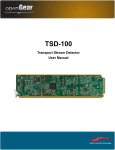
1
TSD-100
Transport Stream Detector
User Manual
Thank you for choosing Ross
You've made a great choice. We expect you will be very happy with your purchase of Ross Technology.
Our mission is to:
1. Provide a Superior Customer Experience
• offer the best product quality and support
2. Make Cool Practical Technology
• develop great products that customers love
Ross has become well known for the Ross Video Code of Ethics. It guides our interactions and
empowers our employees. I hope you enjoy reading it below.
If anything at all with your Ross experience does not live up to your expectations be sure to reach out to
us at [email protected].
David Ross
CEO, Ross Video
[email protected]
Ross Video Code of Ethics
Any company is the sum total of the people that make things happen. At Ross, our employees are a
special group. Our employees truly care about doing a great job and delivering a high quality customer
experience every day. This code of ethics hangs on the wall of all Ross Video locations to guide our
behavior:
1. We will always act in our customers’ best interest.
2. We will do our best to understand our customers’ requirements.
3. We will not ship crap.
4. We will be great to work with.
5. We will do something extra for our customers, as an apology, when something big goes wrong and
it's our fault.
6. We will keep our promises.
7. We will treat the competition with respect.
8. We will cooperate with and help other friendly companies.
9. We will go above and beyond in times of crisis. If there's no one to authorize the required action in
times of company or customer crisis - do what you know in your heart is right. (You may rent
helicopters if necessary.)
TSD-100 User Manual
•
Ross Part Number: TSD100DR-004-05
•
Release Date: July 28, 2014.
Copyright
© 2014 Ross Video Limited. Ross®, openGear®, and any related marks are trademarks or
registered trademarks of Ross Video Ltd. All other trademarks are the property of their respective
companies. PATENTS ISSUED and PENDING. All rights reserved. No part of this publication
may be reproduced, stored in a retrieval system, or transmitted in any form or by any means,
mechanical, photocopying, recording or otherwise, without the prior written permission of Ross
Video. While every precaution has been taken in the preparation of this document, Ross Video
assumes no responsibility for errors or omissions. Neither is any liability assumed for damages
resulting from the use of the information contained herein.
Patents
Patent numbers US 7,034,886; US 7,508,455; US 7,602,446; US 7,802,802 B2; US 7,834,886;
US 7,914,332; US 8,307,284; US 8,407,374 B2; US 8,499,019 B2; US 8,519,949 B2; US
8,743,292 B2; GB 2,419,119 B; GB 2,447,380 B; and other patents pending.
Important Regulatory and Safety Notices to Service Personnel
Before using this product and nay associated equipment, refer to the “Important Safety
Instructions” listed below to avoid personnel injury and to prevent product damage.
Product may require specific equipment, and/or installation procedures to be carried out to satisfy
certain regulatory compliance requirements. Notices have been included in this publication to call
attention to these specific requirements.
Symbol Meanings
This symbol on the equipment refers you to important operating and maintenance (servicing)
instructions within the Product Manual Documentation. Failure to heed this information may
present a major risk of damage to persons or equipment.
Warning — The symbol with the word “Warning” within the equipment manual indicates a
potentially hazardous situation, which, if not avoided, could result in death or serious injury.
Caution — The symbol with the word “Caution” within the equipment manual indicates a
potentially hazardous situation, which, if not avoided, may result in minor or moderate injury. It
may also be used to alert against unsafe practices.
Notice — The symbol with the word “Notice” within the equipment manual indicates a
potentially hazardous situation, which, if not avoided, may result in major or minor equipment
damage or a situation which could place the equipment in a non-compliant operating state.
ESD Susceptibility — This symbol is used to alert the user that an electrical or electronic
device or assembly is susceptible to damage from an ESD event.
Important Safety Instructions
Caution — This product is intended to be a component product of the DFR-8300 series and
OG3-FR series frame. Refer to the DFR-8300 Series and OG3-FR Series Frame User Manual
for important safety instructions regarding the proper installation and safe operation of the
frame as well as its component products.
Warning — Certain parts of this equipment namely the power supply area still present a
safety hazard, with the power switch in the OFF position. To avoid electrical shock, disconnect
all A/C power cords from the chassis’ rear appliance connectors before servicing this area.
Warning — Service barriers within this product are intended to protect the operator and
service personnel from hazardous voltages. For continued safety, replace all barriers after any
servicing.
This product contains safety critical parts, which if incorrectly replaced may present a risk of
fire or electrical shock. Components contained with the product’s power supplies and power
supply area, are not intended to be customer serviced and should be returned to the factory for
repair. To reduce the risk of fire, replacement fuses must be the same time and rating. Only use
attachments/accessories specified by the manufacturer.
EMC Notices
United States of America
FCC Part 15
This equipment has been tested and found to comply with the limits for a class A Digital device,
pursuant to part 15 of the FCC Rules. These limits are designed to provide reasonable protection
against harmful interference when the equipment is operated in a commercial environment. This
equipment generates, uses, and can radiate radio frequency energy and, if not installed and used
in accordance with the instruction manual, may cause harmful interference to radio
communications. Operation of this equipment in a residential area is likely to cause harmful
interference in which case the user will be required to correct the interference at their own
expense.
Notice — Changes or modifications to this equipment not expressly approved by Ross Video
Limited could void the user’s authority to operate this equipment.
CANADA
This Class “A” digital apparatus complies with Canadian ICES-003.
Cet appariel numerique de la classe “A” est conforme a la norme NMB-003 du Canada.
EUROPE
This equipment is in compliance with the essential requirements and other relevant provisions of
CE Directive 93/68/EEC.
INTERNATIONAL
This equipment has been tested to CISPR 22:1997 along with amendments A1:2000 and
A2:2002, and found to comply with the limits for a Class A Digital device.
Notice — This is a Class A product. In domestic environments, this product may cause radio
interference, in which case the user may have to take adequate measures.
Maintenance/User Serviceable Parts
Routine maintenance to this openGear product is not required. This product contains no user
serviceable parts. If the module does not appear to be working properly, please contact Technical
Support using the numbers listed under the “Contact Us” section on the last page of this manual.
All openGear products are covered by a generous 5-year warranty and will be repaired without
charge for materials or labor within this period. See the “Warranty and Repair Policy” section in
this manual for details.
Environmental Information
The equipment that you purchased required the extraction and use of natural
resources for its production. It may contain hazardous substances that could
impact health and the environment.
To avoid the potential release of those substances into the environment and to diminish the need
for the extraction of natural resources, Ross Video encourages you to use the appropriate
take-back systems. These systems will reuse or recycle most of the materials from your
end-of-life equipment in an environmentally friendly and health conscious manner.
The crossed out wheelie bin symbol invites you to use these systems.
If you need more information on the collection, re-use, and recycling systems, please contact your
local or regional waste administration.
You can also contact Ross Video for more information on the environmental performance of our
products.
Company Address
Ross Video Limited
Ross Video Incorporated
8 John Street
P.O. Box 880
Iroquois, Ontario, K0E 1K0
Ogdensburg, New York
Canada
USA 13669-0880
General Business Office: (+1) 613 • 652 • 4886
Fax: (+1) 613 • 652 • 4425
Technical Support: (+1) 613 • 652 • 4886
After Hours Emergency: (+1) 613 • 349 • 0006
E-mail (Technical Support): [email protected]
E-mail (General Information): [email protected]
Website: http://www.rossvideo.com
Contents
Introduction
1
Overview.............................................................................................................................. 1-2
Features.................................................................................................................. 1-2
Functional Block Diagram................................................................................................... 1-3
User Interfaces ..................................................................................................................... 1-4
DashBoard Control System ................................................................................... 1-4
On-screen Menu System........................................................................................ 1-4
SNMP Monitoring and Control ............................................................................. 1-4
Documentation Terms and Conventions.............................................................................. 1-5
Installation
2
Before You Begin ................................................................................................................ 2-2
Static Discharge..................................................................................................... 2-2
Unpacking.............................................................................................................. 2-2
Quick Start ........................................................................................................................... 2-3
Installing the TSD-100......................................................................................................... 2-4
Rear Modules for the TSD-100 ............................................................................. 2-4
Installing a Rear Module ....................................................................................... 2-4
Cabling for the TSD-100 ..................................................................................................... 2-6
Rear Module Cabling ............................................................................................ 2-6
Connections Overview .......................................................................................... 2-6
Software Upgrades............................................................................................................... 2-8
User Controls
3
Card Overview ..................................................................................................................... 3-2
Control and Monitoring Features......................................................................................... 3-3
Status and Selection LEDs on the TSD-100.......................................................... 3-3
Configuration
4
General Settings ................................................................................................................... 4-2
Time Settings ....................................................................................................................... 4-3
Defining Triggers................................................................................................................. 4-5
Setting Names ...................................................................................................................... 4-7
Setting Alarm Sensitivity..................................................................................................... 4-8
Reviewing the Event Log .................................................................................................... 4-9
Monitoring ......................................................................................................................... 4-10
Using the On-Screen Menus
5
On-screen Display Overview............................................................................................... 5-2
OSD Switch Overview .......................................................................................... 5-2
OSD Layout and Navigation................................................................................................ 5-3
Using the Menus .................................................................................................................. 5-4
TSD-100 User Manual (Iss. 05)
Contents • i
Specifications
6
Technical Specifications ...................................................................................................... 6-2
Service Information
7
Troubleshooting Checklist ................................................................................................... 7-2
Reset Button........................................................................................................... 7-2
Warranty and Repair Policy ................................................................................................. 7-3
ii • Contents
TSD-100 User Manual (Iss. 05)
Introduction
In This Chapter
This chapter contains the following sections:
•
Overview
•
Functional Block Diagram
•
User Interfaces
•
Documentation Terms and Conventions
A Word of Thanks
Congratulations on choosing an openGear TSD-100 Transport Stream Detector. Your TSD-100 is
part of a full line of Digital Products within the openGear Terminal Equipment family of
products, backed by Ross Video’s experience in engineering and design expertise since 1974.
You will be pleased at how easily your new TSD-100 fits into your overall working environment.
Equally pleasing is the product quality, reliability and functionality. Thank you for joining the
group of worldwide satisfied Ross Video customers!
Should you have a question pertaining to the installation or operation of your TSD-100, please
contact us at the numbers listed on the back cover of this manual. Our technical support staff is
always available for consultation, training, or service.
TSD-100 User Manual (Iss. 05)
Introduction • 1–1
Overview
The TSD-100 analyzes an MPEG II Transport Stream, and identifies occurrences of selected
components of the stream. For example, SCTE-35 triggers are carried with PID values that are
specified by the system operator. The TSD-100 can alert an operator to the occurrence of the
SCTE-35 trigger, either by recognizing the splice-insert commands or simply by detecting the
presence of the trigger PID.
The TSD-100 provides a number of innovative tools to simplify your workflow. For example:
•
It can monitor up to 8 selected PIDs and associate them with eight GPIO outputs,
allowing you to monitor multiple services with one TSD-100 card.
•
In SCTE-35 trigger mode, GPIO outputs are controlled by both types of splice-insert
(DPI) commands: Out and In, and Out with duration.
•
In SCTE-35 trigger mode, the TSD-100 can be set to match on specific values of the
Splice_insert_ID code in addition to the PID, for additional flexibility.
•
In PID detected mode, each GPIO output is triggered by the arrival of a transport stream
packet with the specified PID, and is then negated after a user-specified timeout. This lets
you control the duration of the output pulse to meet your system requirements.
•
Each GPIO output can indicate either the presence or the absence of a specified PID. For
example, it can be asserted for one minute whenever the PID occurs, or it can indicate
that the PID has not occurred in the last hour.
•
As a member of the openGear family, the TSD-100 shares a common control interface,
known as DashBoard, with a broad array of other products.
•
Each GPIO output can be specified to either close for the full duration of a trigger, or
pulse briefly to indicate the start or end of a trigger.
•
An on-board log of trigger events can be browsed from DashBoard, allowing later
verification of the occurrence of specific triggers.
For maximum flexibility of configuration, the TSD-100 also provides a Heads-Up Display on an
analog video output. When activated, card status and parameters can be viewed and adjusted
using the card-mounted finger joystick and an easy to use menu system.
Features
The following features make the TSD-100 the solution of choice for monitoring selected PIDs in
MPEG Transport Streams:
1–2 • Introduction
•
ASI input on a 75ohm BNC jack located on the rear module
•
Up to 8 PIDs can be monitored, corresponding to the maximum of 8 PIDs that can be
assigned to SCTE-35 triggers
•
GUI and card-edge interfaces for setup and monitoring
•
Individual GPIOs can be set to indicate either presence or absence of selected services
•
Cards are hot-pluggable for ease of configuration and maintenance
•
Relay contact closures for compatibility with a broad range of monitoring equipment
•
Supports DataSafe
•
Compatible with openGear frames
•
Compatible with the openGear frame’s SNMP option
•
5-year transferable warranty
TSD-100 User Manual (Iss. 05)
Functional Block Diagram
This section provides the functional block diagram that outlines the workflow of the TSD-100.
ASI IN
EQUALIZE/
DESERIALIZE
SERIALIZE
ANALYZE
TS
ASI OUT
RELAYS
GPIOs
CPU
OSD
VIDEO
DAC
OSD SD ANLG OUT
Figure 1.1 Simplified Block Diagram — TSD-100
TSD-100 User Manual (Iss. 05)
Introduction • 1–3
User Interfaces
The TSD-100 includes three user interfaces.
DashBoard Control System
The DashBoard Control System enables you to monitor and control openGear frames and cards
from a computer. DashBoard communicates with other cards in the frame through the Network
Controller Card. The DashBoard Control System software and manual are available for download
from our website.
For More Information on...
•
using DashBoard, refer to the DashBoard User Manual available from our website.
On-screen Menu System
For maximum flexibility of configuration, the TSD-100 also provides a Heads-Up Display on an
analog video output. When activated, card status and parameters can be viewed and adjusted
using the card-mounted finger joystick and an easy to use menu system.
For More Information on...
•
the card-edge controls, refer to the section “Card Overview” on page 3-2.
•
the on-screen menu system, refer to the chapter “Using the On-Screen Menus” on
page 5-1.
SNMP Monitoring and Control
The Network Controller Card in the openGear frame provides optional support for remote
monitoring of your frame and the using Simple Network Management Protocol (SNMP), which is
compatible with many third-party monitoring and control tools.
For More Information on...
1–4 • Introduction
•
the SNMP controls on this card, refer to your TSD-100 Management Information Base
(MIB) file.
•
SNMP Monitoring and Control, refer to the MFC-8300 Series User Manual.
TSD-100 User Manual (Iss. 05)
Documentation Terms and Conventions
The following terms and conventions are used throughout this manual.
Terms
The following terms are used:
•
“Board”, and “Card” refer to openGear terminal devices within openGear frames,
including all components and switches.
•
“DashBoard” refers to the DashBoard Control System.
•
“DFR-8300 series frame” includes all versions of the DFR-8310 series frame,
DFR-8321 series frame, and any available options unless otherwise noted.
•
“Frame” refers to openGear frame that houses the TSD-100 card, as well as any
openGear frames.
•
“openGear frame” includes all versions of the DFR-8300 series frame, OG3-FR Series
frame, and any available options unless otherwise noted.
•
“PAT” refers to the Program Association Table.
•
“PID” refers to the Packet Identifier.
•
“PMT” refers to the Program Map Tables.
•
“Rear Module” refers to the connector module at the rear of the frame, into which the
TSD-100 is inserted.
•
“SDT” refers to the Service Descriptor Table.
•
“System” and “Video system” refer to the mix of interconnected production and terminal
equipment in your environment.
•
“TS” refers to transport stream.
Conventions
The following conventions are used:
•
The “Operating Tips” and “Note” boxes are used throughout this manual to provide
additional user information.
TSD-100 User Manual (Iss. 05)
Introduction • 1–5
1–6 • Introduction
TSD-100 User Manual (Iss. 05)
Installation
In This Chapter
This chapter provides instructions for installing the TSD-100, installing the card into the frame,
cabling details, and updating the card software.
The following topics are discussed:
•
Before You Begin
•
Quick Start
•
Installing the TSD-100
•
Cabling for the TSD-100
•
Software Upgrades
TSD-100 User Manual (Iss. 05)
Installation • 2–1
Before You Begin
Before proceeding with the instructions in this chapter, ensure that your openGear frame is
properly installed according to the instructions in its manual.
Static Discharge
Throughout this chapter, please heed the following cautionary note:
ESD Susceptibility — Static discharge can cause serious damage to sensitive
semiconductor devices. Avoid handling circuit boards in high static environments such as
carpeted areas and when synthetic fiber clothing is worn. Always exercise proper grounding
precautions when working on circuit boards and related equipment.
Unpacking
Unpack each TSD-100 you received from the shipping container and ensure that all items are
included. If any items are missing or damaged, contact your sales representative or Ross Video
directly.
2–2 • Installation
TSD-100 User Manual (Iss. 05)
Quick Start
Assuming you have an openGear frame, a TSD-100 card, and a compatible rear module, the
following steps will get you started with SCTE-35 trigger detection:
1. Connect the openGear frame to your LAN. Refer to the DFR-8300 Series and OG3-FR
Series Frames User Manual and MFC-8300 Series User Manual for details.
2. Ensure that DashBoard is installed on a computer connected to the LAN. The
DashBoard software and user manual are available from the Ross Video website.
3. Install the rear module in the frame as described in the section “Installing a Rear
Module” on page 2-4.
4. Install the TSD-100 in the rear module as described in the section “Installing the
TSD-100” on page 2-5.
5. Connect an ASI signal to the ASI connector on the rear modules as specified in the
section “Cabling for the TSD-100” on page 2-6.
6. Power on the openGear frame.
7. Launch the DashBoard client on your computer. DashBoard should automatically
display the frame node in the Basic Tree View.
8. Expand the frame node in the Basic Tree View to display the list of cards installed in that
frame.
9. Double-click the TSD-100 node in the Basic Tree View to display a tab in the Device
View of the DashBoard client.
10. Set up your triggers as follows:
•
Select the SCTE 35 PIDS tab. Make a note of the PIDs listed.
•
Select the GPIO tab.
•
Using the PIDs that are listed in the SCTE 35 PIDs tab, set up your triggers as
outlined in the section “Defining Triggers” on page 4-5.
11. Select the GPIO Counters tab. When triggers are received, they will be counted in this
tab. Note that this could take some time, since the interval between avails may be 30
minutes or more.
12. Connect wires from the GPIO jacks on the rear panel to your monitoring equipment as
described in the section “Cabling for the TSD-100” on page 2-6.
TSD-100 User Manual (Iss. 05)
Installation • 2–3
Installing the TSD-100
This section outlines how to install a rear module and a card in a openGear frame.
Rear Modules for the TSD-100
When installing the TSD-100:
•
DFR-8310 series frame — The MDL-R02 Full Rear Module is required. The TSD-100
is not compatible with the DFR-8310-BNC frame.
•
DFR-8321 series and OG3-FR series frames — The MDL-R22 Full Rear Module is
required.
Installing a Rear Module
If the Rear Module is already installed, proceed to the section “Installing the TSD-100” on page
2-5.
To install a rear module in your openGear frame
1. Locate the card frame slots on the rear of the frame.
2. Remove the Blank Plate from the slot you have chosen for the TSD-100 installation.
3. Install the bottom of the Rear Module in the Module Seating Slot at the base of the
frame’s back plane. (Figure 2.1)
Screw Hole
Module Seating Slots
Figure 2.1 Rear Module Installation (TSD-100 not shown)
4. Align the top hole of the Rear Module with the screw on the top-edge of the frame back
plane.
5. Using a Phillips screwdriver and the supplied screw, fasten the Rear Module to the back
plane of the frame. Do not over tighten.
6. Ensure proper frame cooling and ventilation by having all rear frame slots covered with
Rear Modules or Blank Plates.
2–4 • Installation
TSD-100 User Manual (Iss. 05)
Installing the TSD-100
Use the following procedure to install the TSD-100 in an openGear frame:
1. Locate the Rear Module you installed in the procedure “Installing a Rear Module” on
page 2-4.
Notice — Heat and power distribution requirements within a frame may dictate specific slot
placements of cards. Cards with many heat-producing components should be arranged to
avoid areas of excess heat build-up, particularly in frames using convectional cooling.
2. Hold the TSD-100 by the edges and carefully align the card-edges with the slots in the
frame.
3. Fully insert the card into the frame until the rear connection plus is properly seated in the
Rear Module.
4. Verify whether your label is self-adhesive by checking the back of the label for a thin
wax sheet. You must remove this wax sheet before affixing the label.
5. Affix the supplied Rear Module Label to the BNC area of the Rear Module.
TSD-100 User Manual (Iss. 05)
Installation • 2–5
Cabling for the TSD-100
This section provides information for connecting cables to the installed Rear Module on the
openGear frames. Connect the input and output cables according to the following sections. It is
not necessary to terminate unused outputs.
Rear Module Cabling
This section provides cabling diagrams for the rear modules. The type of rear module depends on
the frame the card is installed in.
DFR-8310 Series Frames
The TSD-100 is used with the MDL-R02. Each rear module occupies one slot and accommodates
one card. This rear module provides one ASI input, one ASI output, one on-screen display (OSD)
analog output, and relay-isolated GPIO outputs. (Figure 2.2)
DFR-8321 Series and OG3-FR Series Frames
The TSD-100 is used with the MDL-R22. Each rear module occupies two slots and
accommodates one card. This rear module provides one ASI input, one ASI output, one OSD
analog output, and relay-isolated GPIO outputs.(Figure 2.2)
ASI In
Not connected
1 2
ASI Out
3 4
GPIOs
OSD ANLG
Out
GPIOs
Figure 2.2 Cable Connections for the MDL-R02 and MDL-R22 Rear Modules
Connections Overview
This section briefly outlines the types of connections available on the rear modules.
ASI In — BNC 1
BNC 1 accepts an ASI video input. The TSD-100 requires this input in all cases. For
convenience, it routes a re-clocked copy of this signal to BNC 3. The input signal is internally
terminated in 75ohms when the TSD-100 is installed.
ASI Out — BNC 3
BNC 3 carries a re-clocked copy of the ASI signal applied to BNC 1.
2–6 • Installation
TSD-100 User Manual (Iss. 05)
OSD ANLG Out — BNC 4
BNC 4 carries an analog video signal (NTSC/525 or PAL/625) that can be connected to an
analog composite video monitor for set up of operating parameters, in conjunction with the Menu
switch (SW2) on the TSD-100 card-edge.
GPIOs
Two blocks of relay-isolated GPIO outputs are provided on each rear module. Refer to Figure 2.3
for MDL-R02 pinouts and Figure 2.4 for MDL-R22 pinouts.
5A
5B
6A
6B
7A
7B
8A
8B
1A
1B
2A
2B
3A
3B
4A
4B
Figure 2.3 GPIO Pinouts for the
MDL-R02 Rear Module
TSD-100 User Manual (Iss. 05)
1A
1B
2A
2B
3A
3B
4A
4B
5A
5B
6A
6B
7A
7B
8A
8B
Figure 2.4 GPIO Pinouts for the
MDL-R22 Rear Module
Installation • 2–7
Software Upgrades
This section provides instructions for upgrading the software for your TSD-100 using the
DashBoard Control System.
To upgrade the software on the TSD-100
1. Contact Ross Technical Support for the latest software version file.
2. Launch the DashBoard client on your computer.
3. Display a tab for the card you wish to upgrade by double-clicking its status indicator in
the Basic Tree View.
4. From the Device tab, click Upload to display the Select File for upload dialog box.
5. Navigate to the *.bin upload file you wish to upload.
6. Click Open and follow the on-screen instructions.
7. Click Finish to start the upgrade.
8. Monitor the upgrade.
•
A Upload Status dialog enables you to monitor the upgrade process.
•
The card reboots automatically once the file is uploaded. The card is temporarily
taken offline.
•
The reboot process is complete once the status indicators for the Card State and
Connection return to their previous status.
Operating Tip — If you are running DashBoard version 2.3.0 or lower, you must
click Reboot in the Device tab to complete the upgrade process.
Troubleshooting
If you encounter problems when upgrading your card software, verify the following:
2–8 • Installation
•
Ethernet cable is properly connected if you are uploading the file via a network
connection.
•
The file you are attempting to load is a *.bin file that is for the card you are upgrading.
TSD-100 User Manual (Iss. 05)
User Controls
In This Chapter
This chapter provides a general overview of the user controls available on the TSD-100.
The following topics are discussed:
•
Card Overview
•
Control and Monitoring Features
TSD-100 User Manual (Iss. 05)
User Controls • 3–1
Card Overview
This section provides a general overview of the TSD-100 components.
1
2
3
Figure 3.1 TSD-100 — Components
1) Bypass Switch (SW1)
2) Menu Switch (SW2)
3) Reset Switch (SW3)
1. Bypass Switch (SW1)
SW1 should be left in the IN position at all times when using the MDL-R22 and MDL-R02 rear
modules.
2. Menu Switch (SW2)
The recommended user interface for the TSD-100 is the DashBoard program, running on a
computer connected to the openGear frame through an Ethernet connection. If your frame does
not have the LAN option, or you do not have access to a computer with DashBoard, you can use
the on-screen display (OSD) in conjunction with SW2. This requires an analog picture monitor
(NSTC or PAL) to be connected to the card via BNC 4 on the rear module. The Menu Switch is a
five-direction square finger joystick located near the front-edge of the TSD-100 card.
3. Reset Switch (SW3)
Use SW3 to reboot the card.
For More Information on...
3–2 • User Controls
•
the LEDs available on the card-edge, refer to the section “Control and Monitoring
Features” on page 3-3.
•
using the on-screen menu system, refer to the chapter “Using the On-Screen Menus” on
page 5-1.
•
rebooting the card, refer to the section “Reset Button” on page 7-2.
TSD-100 User Manual (Iss. 05)
Control and Monitoring Features
This section provides information on the jumpers, buttons and LEDs for the TSD-100. Refer to
Figure 3.2 for the location of the LEDs.
POWER LED (DS1)
BYPASS LED (DS2)
Bypass Switch (SW1)
ASI IN LED (DS3)
ASI OUT LED (DS4)
DS5 LED
OSD SDI OUT LED (DS6)
Menu Switch (SW2)
UNSUPPORTED REAR MODULE LED (DS7)
BYPASS LED (DS8)
NO VIDEO LED (DS9)
UNKNOWN REAR MODULE LED (DS10)
Reset Button (SW3)
Figure 3.2 TSD-100 Card-edge Controls
Status and Selection LEDs on the TSD-100
The front-edge of the TSD-100 has LED indicators for communication activity. Basic LED
displays and descriptions are provided in Table 3.1.
Table 3.1 LEDs on the TSD-100
LED
POWER
(DS1)
BYPASS
(DS2)
Color
Green
Flashing Green
When flashing green, this LED indicates that the bootloader is
waiting for a software upload.
Yellow
When lit orange, this LED indicates there is a warning for a
signal or a configuration error is occurring.
Red
When lit red, this LED indicates that the card is not operational.
This will occur if, for example, there is not video input.
Off
When off, this LED indicates that there is no power.
Red
Off
TSD-100 User Manual (Iss. 05)
Display and Description
When lit green, this LED indicates that the card is running with
a valid input.
When lit red, this LED indicates that the card has been disabled
by the Bypass switch (MDL-R22 rear modules).
With other rear modules with bypass relays, this would indicate
that the ASI bypass is engaged.
When off, this LED indicates the card is in the video path.
User Controls • 3–3
Table 3.1 LEDs on the TSD-100
LED
Color
Green
When lit green, this LED indicates the ASI input is present and
valid.
Off
When unlit red, this LED indicates no valid input is present.
Ensure the input cable is connected properly.
Green
When lit green, this LED indicates the ASI output serializer is
locked to a valid input.
ASI IN (DS3)
ASI OUT
(DS4)
Display and Description
This LED is not implemented.
DS5
OSD SDI Out Green
(DS6)
When lit green, the OSD output serializer is locked to the
on-board oscillator.
Green
Unsupported
Rear Module
Red
(DS7)
When lit green, this LED indicates a supported rear module.
BYPASS
(DS8)
NO VIDEO
(DS9)
UKNOWN
REAR
MODULE
(DS10)
3–4 • User Controls
When lit red, this LED indicates that the rear module connected
to the TSD-100 is not supported by the software. Operation will
not be correct.
Yellow
When lit yellow, this LED indicates that the card is in the video
path.
Red
When lit red, this LED indicates the card’s ASI is bypassed.
(redundant with DS2).
Green
When lit green, this LED indicates a valid video input.
Red
When lit red, this LED indicates that no video is present at the
input.
Green
When lit green, this LED indicates a supported rear module is
installed with the card.
Orange
When lit orange, this LED indicates this indicates that the rear
module connected to the TSD-100 is not one of the types
recognized by the software. Operation may not be correct.
TSD-100 User Manual (Iss. 05)
Configuration
In This Chapter
This chapter explains how to use the user interface to set up the TSD-100. This discussion is
based on the use of DashBoard through a network connection, however these functions are also
available through the local Heads-up Display.
The following topics are discussed:
•
General Settings
•
Time Settings
•
Defining Triggers
•
Setting Names
•
Setting Alarm Sensitivity
•
Reviewing the Event Log
•
Monitoring
TSD-100 User Manual (Iss. 05)
Configuration • 4–1
General Settings
This section outlines the options displayed by clicking the Settings tab.
Settings Tab
OSD Background Color, OSD Video Type
The OSD Background Color and Video Type default to black and 525 lines/59.94 Hz,
respectively. If you plan to use the on-screen display and need different settings for these, you can
select them here; they take effect immediately.
GPIO Counters
The Reset button clears all trigger counters to 0. Consequently, these counters reflect the number
of triggers of each type that have occurred since the last time you clicked this button, or since
power-on.
Factory Defaults
The Reset button restores the settings of the TSD-100 card to the values they had when you first
received the card. This can be a convenient way of returning the card to a known, fixed state.
Note — The TSD-100 supports the DataSafe feature in DashBoard. Refer to the
MFC-8300 Series Controller Cards User Manual for details on using this feature.
Show Program Names
When selected, the Show Program Names check box allows decoding of the program names for
the SCTE 35 from the Service Descriptor Table (SDT). Before selecting this box, verify that a
valid SDT is present in the video signal. Note that the check box is unselected (cleared) by
default.
SCTE PIDS
The SCTE 35 PIDs Refresh button updates the contents of the SCTE PIDs menu.
4–2 • Configuration
TSD-100 User Manual (Iss. 05)
Time Settings
The following screen capture shows the screen that is used to set up the time reference for the
TSD-100. This is used in time-stamping events as they are recorded in the log.
Time Tab
Time Source
The time source be set to either Network Time or Manual. If you have access to a Network Time
(NTP) server through the openGear frame’s LAN connection, you can configure the frame to
obtain the time and date from that server. Once this is done, you can select Network Time for this
setting. This is the preferred method since it is typically very accurate. If you do not have access
to an NTP server on your local network, you can try using one on the Internet; see
http://support.ntp.org/bin/view/Servers/WebHome for a list of servers. If this is not available,
select Manual instead.
UFC Offset
UTC Offset HH:MM is the time difference between Standard Time at your location and
Universal Coordinated Time (also known as GMT) which is used in NTP services.
•
If you are using Network Time as described in the previous point, you need to set this
value so that the time used in the event log (and displayed on the Product tab) is your
local time. The example shows an offset of minus 5 hours, which is correct for Eastern
Time in North America. If you are not sure of the offset for your location, visit a time
zone Internet site such as http://www.worldtimezone.com.
•
If you are using Manual Time, set the offset to 0.
DST
DST should be set to Enabled if Daylight Saving Time (DST) is observed in your area, and
Disabled if not. This applies to both Network Time and Manual time setting methods. During
the portion of the year when DST is in effect, this adds one hour to the time, in addition to the
offset you specified for Network Time.
TSD-100 User Manual (Iss. 05)
Configuration • 4–3
Manual Date and Time
Manual Date YYYY/MM/ DD and Manual Time HH:MM:SS fields are for use in setting the
time manually. If you are using Network Time, leave these blank. If you are using Manual Time,
enter the time and date in the indicated format and then click Time Settings Accept.
After you have made the desired time settings and clicked Accept, the Product tab should
display your current local time and date. If these are incorrect, check your settings before
proceeding.
In order to use network time, you also need to ensure that the Network Controller Card in the
openGear frame has been configured to acquire time from an NTP server. To do this, refer to the
manual for your Network Controller Card for details.
If you do not have access to an NTP server, you can enter the time and date directly on the Time
tab, select Manual and click Accept.
4–4 • Configuration
TSD-100 User Manual (Iss. 05)
Defining Triggers
This GPIO tab allows you to define the parameters for reporting the presence of individual PIDs
in the ASI input.
GPIO Tab — Settings for SCTE-35 Trigger Presence Detection
For each of the eight GPIO outputs, which you select using the sub-tabs located at the bottom of
the GPIO tab, you will need to specify the following:
GPIO PID
PID value, in the range 0-8191 decimal.
Trigger Condition
Select one of the following from the Condition options: PID Detected, SCTE-35 Automatic,
SCTE-35 avail start, SCTE-35 avail end or None.
•
When PID Detected is selected, any packet bearing the specified PID value is treated as
a trigger; the GPIO output is asserted for the duration specified by the Timeout field.
•
When SCTE-35 Automatic is selected, the GPIO output changes state when an
SCTE-35 “splice-insert” command is received with the specified PID. It is asserted when
the “out-of-network-indicator” is 1, and negated when it is 0. That is, it is asserted for the
duration of an avail. If the “out-of-network-indicator” is 1 and the command contains a
duration, the output will be asserted for the specified duration and then automatically
negated.
•
When SCTE-35 avail start is selected, the GPIO output is asserted for a brief period of
time when a “splice-insert” command is received with the specified PID and the
“out-of-network-indicator” = 1, i.e. at the start of an avail. The pulse duration is set by the
Timeout parameter.
•
When SCTE-35 avail end is selected, the GPIO output is asserted for a brief period of
time at the end of an avail. This occurs when a “splice-insert” command is received with
the specified PID and the “out-of-network-indicator” = 0, or when an avail ends because
its duration has expired. The pulse duration is set by the Timeout parameter.
•
When None is selected, the GPIO is disabled.
TSD-100 User Manual (Iss. 05)
Configuration • 4–5
Match on Splice Event ID and Splice Event ID
The Splice Event ID is a number contained in each SCTE-35 splice command. To react to all
splice commands on the specified PID, you should leave the Match on Splice Event ID box with
no check mark; this is the default setting. If you want only a specific value of Splice Event ID to
trigger the GPIO, you should check this box and enter the desired value. This is a decimal value
between 0 and 2,147,483,647. If you do not know the values that are available, define your
desired GPIOs with the check box unchecked, wait long enough for each of the triggers to be
detected, and examine the Event Log to find the values that have occurred.
Timeout
The Timeout fields are in hours (HH), minutes (MM), seconds (SS) and milliseconds (mS). Note
that the duration is somewhat variable and may be up to 0.1 second (100 milliseconds) less than
the value specified.
•
When the Trigger Condition is PID Detected, each occurrence of a Transport Stream
packet bearing the target PID causes the GPIO output to be asserted for this period of
time.
•
When the Trigger Condition is SCTE-35 Automatic, the timeout can be used to clear
the GPIO in the event that the “splice-insert” command marking the end of an avail is
missed; in this case, it should be set to a larger value than the expected avail duration.
When Timeout is set to 0, this automatic clear is disabled and the GPIO follows the
“out-of-network-indicator” exactly.
•
When the Trigger Condition is SCTE-35 avail start or SCTE-35 avail end, the timeout
specifies the duration of the pulse that is produced.
Trigger Delay
This field allows the GPIO pulse signal to be delayed if required for compatibility with connected
equipment. This should normally be set to 0 unless you know that a delay is needed. Note that the
delay is somewhat variable and may be up to 0.1 second (100 milliseconds) less than the value
specified.
Retriggerable
Select between Yes or No as follows:
•
If this is set to Yes and Trigger Condition is PID Detected, any occurrences of the target
PID that occur while the GPIO is already asserted cause the timeout period to be
restarted: the GPIO will remain asserted until one timeout period after the final
occurrence of the target PID; if the target PID interval is shorter than the timeout, the
GPIO output will stay asserted permanently.
•
If this is set to No, the TSD-100 ignores any occurrences of the target PID that occur
while the GPIO is already asserted. This should be set to No when Trigger Condition is
SCTE-35 Automatic or SCTE-35 avail start or SCTE-35 avail end.
Active
This specifies the state of the relay contacts (High or Low) when the GPIO is asserted.
Set Trigger
Select Accept to apply your changes.
4–6 • Configuration
TSD-100 User Manual (Iss. 05)
Setting Names
The Edit Strings tab allows you to specify names (up to 15 characters each) that you want to
assign to the module and to its GPIO outputs, in order to uniquely identify them in your system.
The default values for these fields are “GPIO” for each of the GPIO outputs and blank for the
Card ID.
If you enter a Card ID and click Apply then Yes, the new module name will be “TSD-100”
followed by the string you typed in (e.g. TSD-100 – Downlink). Since this changes the name of
the module, its previous name disappears from the device list in the Basic Tree View and the new
name appears in its place.
Names that you enter for the GPIOs are used in the Trigger Counters and GPIO Output status
displays. In each case, the GPIO number is also displayed.
Edit Strings Tab
TSD-100 User Manual (Iss. 05)
Configuration • 4–7
Setting Alarm Sensitivity
The Alarms tab allows you to specify which conditions in the TSD-100 will cause an alarm
indication on your DashBoard screen and on-screen display output, and an SNMP trap if enabled.
Whenever any of the enabled alarm conditions becomes true, the color of the indicator for the
TSD-100 on the DashBoard screen switches from green to red.
Alarms Tab
Unsupported Rear Module
An error is reported when the TSD-100 is plugged into an incompatible rear module, which
prevents it from operating correctly.
In Bypass
In Bypass means that the TSD-100’s video is bypassed. This is because the card-edge Bypass
push-button is in the Out position. If this alarm is enabled and this condition occurs, the In
Bypass field on the Alarms status tab displays the message “In Bypass”. This means that the
card is completely disabled.
No Video
An error is reported when no recognizable signal is detected on the ASI input.
Unknown Rear Module
An error is reported when the TSD-100 is plugged into a rear module that it does not recognize.
This means that it may not operate correctly, depending on the connectors and features of the
unknown rear module.
4–8 • Configuration
TSD-100 User Manual (Iss. 05)
Reviewing the Event Log
The TSD-100 maintains a list of trigger events and presents them in reverse chronological order
in the Log display. An example is shown in the following screen capture. Each entry includes the
GPIO number, date and time, Splice Event ID, and type of event. For example: “GPIO 1
(2008/11/28, 16:13:38) Id:1201 End”.
Example of Log Tab with Entries
The GPIO selector below the log entries can be used to filter the list entries for display. For
example, if you want to examine events that occurred on GPIO 1 and eliminate clutter caused by
other events, select GPIO 1 in this selector and then click Refresh. Select All Log Messages and
Refresh to view all events.
The Log tab displays the last 20 of a possible 2000 log entries. At a typical rate of 2 trigger events
per hour, it will hold over 20 days of triggers for one GPIO or 2.6 days for eight GPIOs. When it
fills, the oldest entries are removed to make room for new ones. You can use the Download
Logfile feature to save the entire log file as a comma separated text file on your computer.
TSD-100 User Manual (Iss. 05)
Configuration • 4–9
Monitoring
The Status tabs provide read-only information such as software revision issue and signal status of
the TSD-100. The fields in the Status tabs vary in severity from green (valid) to red (alarm).
DashBoard reports the most severe alarm for a single field.
Status Tabs — Product Tab Selected
Product Tab
The Product tab provides read-only information, such as board revision, serial number, and rear
module type. This information is helpful to a Ross Video technical support when there are
questions about the operation of the unit.
Alarms Tab
The alarm conditions listed in the Alarms status tab are qualified by the selections made on the
Alarms setup tab.
•
Card Status — Any error conditions that are checked on the Alarms setup tab will cause
the Card Status field to report red when they occur. Alarm conditions that are unchecked
will be ignored.
•
Unsupported Rear Module — This fields reports when the TSD-100 does not work
properly with this rear module; for example, it may be missing jacks that are essential for
the TSD-100 operation.
•
In Bypass — This field reports when the on-board Bypass push-button has been
activated. This may be an error condition, since it disconnects the card’s ASI input if the
rear module provides bypass capability.
•
No Video — This field reports when the ASI input signal is not connected to a valid ASI
video source.
•
Unknown Rear Module — This field reports when the TSD-100 does not recognize this
rear module and thus may not work properly.
GPIO Output Tab
The GPIO Output tab reports the present state of the eight GPIO outputs including the video
type and bypass state, as well as the present state of each of the eight GPIO outputs.
4–10 • Configuration
TSD-100 User Manual (Iss. 05)
When using the TSD-100 with a rear module that provides relay contacts, the states are listed as
“Open” or “Closed”. Otherwise the states would be listed as “High” or “Low”, reflecting the
corresponding logic levels.
GPIO Counters Tab
The GPIO Counters tab displays information about occurrences of each of the trigger events that
the user has defined.
•
The left-most number in these fields is the cumulative number of trigger events that have
occurred since the counters were last reset. The Settings tab has a Trigger Counters
Reset button that restores all counters to 0.
•
The Elapsed time is the running time since the most recent occurrence of the trigger
event.
•
The second timestamp, if one is displayed, is the last observed Interval between triggers.
Refer to the section “Defining Triggers” on page 4-5 for details on how to set up the GPIOs to
reflect the presence of SCTE-35 triggers or specified PIDs in the ASI input, and how to specify
the names of the services associated with these triggers. The names are GPIO 1 through GPIO 8
by default. You can change the names using the options in the Edit Strings tab.
SCTE 35 PIDs Tab
The SCTE 35 PIDs tab provides a list of all SCTE 35 trigger PIDs that are defined in the
incoming Transport Stream (TS). The Program Association Table (PAT) contains Program
Numbers and PIDs that are used to find the Program Map Tables (PMTs). PMTs may contain the
PIDs of SCTE 35 triggers. For each program that contains triggers, the program number and
trigger PID are displayed in the list. If the Service Descriptor Table (SDT) is present, the names
of the programs are also displayed. This list is constantly refreshed from the incoming TS.
The PIDs listed in this tab are the information that you will need to enter in the GPIO tab, as
discussed in earlier in this chapter. Note that this tab only displays the triggers that are expected to
be present in the TS, based on the information in the PMTs. The presence of the triggers
themselves is shown in the GPIO Counters tab.
TSD-100 User Manual (Iss. 05)
Configuration • 4–11
4–12 • Configuration
TSD-100 User Manual (Iss. 05)
Using the On-Screen Menus
In This Chapter
This chapter explains how to use the Menu switch (SW3) functions available on the On-screen
Display (OSD) of the TSD-100. It does not describe each available menu; for information on
these, refer to the chapter “Configuration” on page 4-1. The purpose of this chapter is to explain
how to navigate the menus and access the available functions and settings.
The following topics are discussed:
•
On-screen Display Overview
•
OSD Layout and Navigation
•
Using the Menus
TSD-100 User Manual (Iss. 05)
Using the On-Screen Menus • 5–1
On-screen Display Overview
This section briefly describes how to access and navigate through the menus in the on-screen
display (OSD). The OSD feature is displayed on a separate composite monitoring output. When
activated, the card status and parameters can be viewed and adjusted using the card-mounted
menu switch and an easy to use menu system.
For More Information on...
•
the switch locations on the card-edge, refer to the section “Card Overview” on page 3-2.
OSD Switch Overview
The Menu switch is used to navigate the TSD-100 menu system and configure item parameters.
This switch is a five-direction, square, finger joystick.
Up
Back
In
Forward
Down
Figure 5.1 Menu Switch
With the card-edge facing you, use the following menu switch actions and (Figure 5.1) to
navigate the menu parameters:
•
In — pressing once brings the menu system onto the monitor output, holding for two
seconds exits the menu system. This position is also used to enter the menu values and
parameters.
•
Up — pressing once selects the menu, item, or value above the current selection, holding
scrolls to the top of the available selections.
•
Down — pressing once selects the menu, item, or value below the current selection,
holding scrolls to the bottom of the available selections.
•
Forward — pressing once moves from menu to item, or item to value.
•
Back — pressing once moves from value to item, or item to menu.
5–2 • Using the On-Screen Menus
TSD-100 User Manual (Iss. 05)
OSD Layout and Navigation
When the TSD-100’s front OSD switch is in the normal “in” position, the OSD is off and its
output BNC is the output from the card. To use the OSD, move it to the “out” position (closer to
the front-edge of the card). A menu, similar shown below, is displayed on the OSD output.
TSD-100 Transport Stream Detector
Product
Settings
Product
Manufacturer
Hardware Rev
Software Rev
Firmware Rev
Rear Module
Current (mA)
Serial Number
Current Time
Current Date
OK
EXIT
TSD-100
A
F
A
40
400
N/A
00:00:00
yyyy/mm/dd
Slot 2
Main OSD Screen — Product Status
The top line of the screen has three items (from left to right): Product, Settings, and Exit.
Product
This is the first in a list of Status screens. To view these screens, press the Menu switch In to
highlight the word Product, then press Menu switch Down once to view the GPIO Status screen,
and Down again for the next screen in the sequence. These are the same Status fields described in
the chapter “Configuration” on page 4-1.
Settings
This is the first in a list of Setup menus. To view these, press the Menu switch Forward to
advance the selection bar to the word Settings, then press the Menu switch In to highlight it.
Now press the Menu switch Down once to view the ASI to 310 menu, and Down again for the
next menu in the sequence. These are the same Setup menus described in the DashBoard Setup
chapter.
Note — While editing numeric fields, Forward and Back allow you to select
individual digits, while Up and Down change the value of the selected digit. Numeric
entry is completed by pressing the Menu switch In. This also applies to editing
alphanumeric values in the Edit Strings menu.
Exit
To turn off the OSD: press the Menu switch Forward to advance the selection bar to the word
Exit, then press the Menu switch In.
To turn the OSD back on, press the Menu switch In again. This selection is somewhat redundant,
since you should return the front OSD switch to the “in” position anyway to turn the OSD off.
TSD-100 User Manual (Iss. 05)
Using the On-Screen Menus • 5–3
Using the Menus
The available menus that can be selected via the OSD are described in Table 5.1.
Table 5.1 Available Menus
Status (left column)
Setup Menus (center column)
Exit (right)
Product
Settings
Exit
GPIO Output
GPIO
Trigger Status
Edit Strings
SCTE 35 PIDS
Alarms
Alarms
Log
The use of the menus to change settings will be illustrated by the following example:
1. Navigate to the Setup Menus entry on the top row, as discussed previously, by using the
Forward and Back positions of the Menu switch.
2. If the Menu name (for example, Settings) is highlighted (brighter than other text), skip
to step 3. If it is not highlighted, press the Menu switch In to highlight it.
3. Press the Menu Switch Down or Up to step through the available menus.
4. When you reach GPIO, select it by pressing the Menu switch In. The display should be
similar to the one shown below.
TSD-100 Transport Stream Detector
GPIO Output
GPIO
GPI01 PID
Condition
Timeout HH
MM
SS
mS
Trggr Delay ms
Retriggerable
Active
Set Trigger
231 [e7h]
SCTE-35 avail end
0
0
0
500
300
No
High
Accept
OK
Slot 2
GPIO Menu
5. Use the scroll bar, located on the right-side of the menu, to scroll through the GPIO
Menu to locate the specific GPIO you wish to configure. Or you can press the Menu
switch Down or Up to step through the available items.
6. When you reach the Condition item for the GPIO you wish to configure, select it by
pressing the Menu switch In.
7. Press the Menu switch Down or Up to step through the available values for the
Condition item.
8. When you reach the desired value (SCTE-35 avail end in this example), select it by
pressing the Menu switch In.
9. Repeat steps 5-8 to select values for the other GPIOs. While editing the numeric fields,
such as Trggr Delay, note that Forward and Back allow you to select individual digits,
while Up and Down change the value of the selected digit. Numeric entry is completed
by pressing the Menu switch In. This also applies to editing alphanumeric values in the
Edit Strings menu.
5–4 • Using the On-Screen Menus
TSD-100 User Manual (Iss. 05)
10. When you have finished setting the parameter values, move the highlight to the word
Accept for that specific GPIO, and press the Menu switch In to put into effect the
changes you have made. Note that this change is applied only to the specified GPIO.
11. To switch to a different menu, press the Menu switch Up or Down repeatedly until the
selection bar moves to the title. Press the Menu Switch In and return to step 3.
TSD-100 User Manual (Iss. 05)
Using the On-Screen Menus • 5–5
5–6 • Using the On-Screen Menus
TSD-100 User Manual (Iss. 05)
Specifications
In This Chapter
This chapter provides the technical specification information for the TSD-100. Note that
technical specifications are subject to change without notice.
The following topics are discussed:
•
Technical Specifications
TSD-100 User Manual (Iss. 05)
Specifications • 6–1
Technical Specifications
This section provides technical specifications for the TSD-100.
Table 6.1 TSD-100 Technical Specifications
Category
Parameter
Number of Inputs
1
Input Signal Standard
Accommodated
DVB-ASI (EN 50083-9)
Transport
Stream Inputs Impedance
Transport
Stream
Outputs
Over 100m of Belden 1694A cable
Return Loss
>15dB to 270MHz
Number of Outputs
1 ASI input monitor
Impedance
75ohm
Return Loss
>10dB to 270MHz
Signal Level
800mV ±10%
DC Offset
0Volts ±50mV
Rise and Fall Time
700ps. typical
Overshoot
<8%
Number of Outputs
1 on-screen display (OSD) output
Formats
GPIO Outputs Number and type of outputs
6–2 • Specifications
75ohm terminating
Equalization
Analog Video Impedance
Output
Signal Level
Power
Specification
Maximum Power Consumption
75ohms
1.0v
NTSC-M or PAL-B/G
8 pairs of isolated contacts (Max 0.1A)
5W
TSD-100 User Manual (Iss. 05)
Service Information
In This Chapter
This chapter contains the following sections:
•
Troubleshooting Checklist
•
Warranty and Repair Policy
TSD-100 User Manual (Iss. 05)
Service Information • 7–1
Troubleshooting Checklist
Routine maintenance to this openGear product is not required. In the event of problems with your
TSD-100, the following basic troubleshooting checklist may help identify the source of the
problem. If the frame still does not appear to be working properly after checking all possible
causes, please contact your openGear products distributor, or the Technical Support department at
the numbers listed under the “Contact Us” section.
1. Visual Review — Performing a quick visual check may reveal many problems, such as
connectors not properly seated or loose cables. Check the card, the frame, and any
associated peripheral equipment for signs of trouble.
2. Power Check — Check the power indicator LED on the distribution frame front panel
for the presence of power. If the power LED is not illuminated, verify that the power
cable is connected to a power source and that power is available at the power main.
Confirm that the power supplies are fully seated in their slots. If the power LED is still
not illuminated, replace the power supply with one that is verified to work.
3. Re-seat the Card in the Frame — Eject the card and re-insert it into the frame.
4. Check Control Settings — Refer to the Installation and User Controls sections of this
manual to verify all user-adjustable component settings
5. Input Signal Status — Verify that source equipment is operating correctly and that a
valid signal is being supplied.
6. Output Signal Path — Verify that destination equipment is operating correctly and
receiving a valid signal.
7. Unit Exchange — Exchanging a suspect unit with a unit that is known to be working
correctly is an efficient method for localizing problems to individual units.
Reset Button
In the unlikely event of a complete card failure, you may be instructed by a Ross Technical
Support specialist to perform a complete software reload on the TSD-100.
To reload the software on the TSD-100
1. Press and hold the Menu switch.
2. While holding the Menu switch, press the Reset button.
3. Release the Reset button and then the Menu switch.
7–2 • Service Information
•
The POWER LED (DS1) will flash green while the card is waiting for a new
software load.
•
If a new software load is not sent to the card within 60 seconds, the card will
attempt to restart with its last operational software load.
•
Software loads can be sent to the TSD-100 via the connection on the rear of the
frame.
TSD-100 User Manual (Iss. 05)
Warranty and Repair Policy
The TSD-100 is warranted to be free of any defect with respect to performance, quality,
reliability, and workmanship for a period of FIVE (5) years from the date of shipment from our
factory. In the event that your TSD-100 proves to be defective in any way during this warranty
period, Ross Video Limited reserves the right to repair or replace this piece of equipment with a
unit of equal or superior performance characteristics.
Should you find that this TSD-100 has failed after your warranty period has expired, we will
repair your defective product should suitable replacement components be available. You, the
owner, will bear any labor and/or part costs incurred in the repair or refurbishment of said
equipment beyond the FIVE (5) year warranty period.
In no event shall Ross Video Limited be liable for direct, indirect, special, incidental, or
consequential damages (including loss of profits) incurred by the use of this product. Implied
warranties are expressly limited to the duration of this warranty.
This TSD-100 User Manual provides all pertinent information for the safe installation and
operation of your openGear Product. Ross Video policy dictates that all repairs to the TSD-100
are to be conducted only by an authorized Ross Video Limited factory representative. Therefore,
any unauthorized attempt to repair this product, by anyone other than an authorized Ross Video
Limited factory representative, will automatically void the warranty. Please contact Ross Video
Technical Support for more information.
In Case of Problems
Should any problem arise with your TSD-100, please contact the Ross Video Technical Support
Department. (Contact information is supplied at the end of this publication.)
A Return Material Authorization number (RMA) will be issued to you, as well as specific
shipping instructions, should you wish our factory to repair your TSD-100. If required, a
temporary replacement frame will be made available at a nominal charge. Any shipping costs
incurred will be the responsibility of you, the customer. All products shipped to you from Ross
Video Limited will be shipped collect.
The Ross Video Technical Support Department will continue to provide advice on any product
manufactured by Ross Video Limited, beyond the warranty period without charge, for the life of
the equipment.
TSD-100 User Manual (Iss. 05)
Service Information • 7–3
Contact Us
Contact our friendly and professional support representatives for the following:
•
Name and address of your local dealer
•
Product information and pricing
•
Technical support
•
Upcoming trade show information
Technical
Support
Telephone: +1 613 • 652 • 4886
After Hours Emergency: +1 613 • 349 • 0006
Email: [email protected]
Telephone: +1 613 • 652 • 4886
General
Information
Fax: +1 613 • 652 • 4425
Email: [email protected]
Website: http://www.rossvideo.com
Visit Us
Visit our website for:
•
Company information and news
•
Related products and full product lines
•
Online catalog
•
Testimonials