1
EDEBDA0204-4514-1_EN
User manual
Technical parameters
multicomp
5D6-ESBSDS-1V1C6RO
System I English
Your partner for
network analysis
© KBR GmbH
Subject to
technical changes
2
Table of contents
KBR multicomp 5D6
Table of contents
1
Introduction............................................................................................................... 6
1.1
User manual................................................................................................................ 6
1.2
Explanation of safety relevant symbols............................................................ 7
1.3
Safety notes................................................................................................................. 8
1.4
Product liability.......................................................................................................... 9
1.5Disposal........................................................................................................................ 9
1.6
Overvoltage and lightning protection.............................................................. 9
2
2.1 2.2
2.3
2.4 Connection of the multicomp 5D6...................................................................10
Installation and assembly.....................................................................................10
Connection chart....................................................................................................12
Terminal assignment..............................................................................................13
Inserting or replacing backup battery.............................................................14
3Commissioning guideline for the multicomp 5D6.....................................16
3.1
Controller not preconfigured..............................................................................16
3.2
Controller not preconfigured..............................................................................18
4Functions of the controller in the secureC
safety and maintenance concept......................................................................20
4.1
Stage resonance frequency monitoring.........................................................20
4.2
Current consumption and performance monitoring of stages..............21
4.3
Current consumption and performance monitoring
of complete cabinets.............................................................................................21
4.4
Temperature monitoring of stages...................................................................23
EDEBDA0204-4514-1_EN
5
5.1 5.2
5.3 5.4
5.5
5.6
5.7
5.8
5.9
5.10
5.10.1
V5.00
Control and display panel....................................................................................25
Description of buttons and displays................................................................25
Navigation and device displays.........................................................................26
Setting range of the parameters configurable:............................................34
Device configuration.............................................................................................35
Start menu Commissioning.................................................................................35
Main menu Cosφ.....................................................................................................36
Main menu Voltage / current..............................................................................39
Main menu Temperature......................................................................................40
Main menu Module management....................................................................41
Main menu Stages..................................................................................................42
Submenu Mode.......................................................................................................43
3
KBR multicomp 5D6
Table of contents
4
6
6.1
6.2
6.3
6.3.1
6.3.2
Basic device configuration...................................................................................78
Set transformer ratio..............................................................................................78
Set target cosφ ........................................................................................................81
Notes on detecting errors....................................................................................82
System and safety devices maintenance........................................................83
Limit temperatures.................................................................................................83
7
7.1
7.2
7.3
7.4
7.5
7.6
7.7
7.8
7.9
7.10
Technical data...........................................................................................................85
Measuring and display values............................................................................85
Measuring accuracy...............................................................................................86
Measuring principle...............................................................................................86
Device memory........................................................................................................86
Power supply............................................................................................................87
Hardware inputs......................................................................................................87
Hardware outputs...................................................................................................88
Mechanical data.......................................................................................................90
Standards and miscellaneous.............................................................................90
Default settings after reset..................................................................................91
8
8.1 8.2
8.2.1
8.2.2 8.2.3
8.2.4
Appendix....................................................................................................................92
General technical data of the modules (without multimess 1D4)........92
Relay output module multisio 2D2 4RO.........................................................93
Relay output module connection chart..........................................................93
Relay output module LED display.....................................................................93
Function of the scan button................................................................................94
Function of the DIP switches..............................................................................94
V5.00
EDEBDA0204-4514-1_EN
5.11
Main menu U h voltage distortion factor ......................................................44
5.12
Main menu I h distortion current strength ..................................................45
5.13
Main menu Extra.....................................................................................................47
5.13.1Commissioning........................................................................................................49
5.13.1.1 Submenu Transformer settings..........................................................................50
5.13.1.2 Submenu Target cosine........................................................................................52
5.13.1.3 Submenu Stages......................................................................................................52
5.13.2Settings.......................................................................................................................56
5.13.2.1 Submenu Modules / display...............................................................................56
5.13.2.2 Submenu System....................................................................................................64
5.13.2.3 Service submenu.....................................................................................................72
5.13.3Messages....................................................................................................................75
5.13.3.1 Submenu Messages...............................................................................................75
Table of contents
KBR multicomp 5D6
8.3
Temperature module multisio 2D2 1TI2RO...................................................95
8.3.1 Temperature module connection chart..........................................................95
8.3.2 Temperature module LED display.....................................................................96
8.3.3 Function of the scan button................................................................................96
8.3.4
Function of the DIP switches..............................................................................97
8.4 multisio 1D2-4CI current measuring module...............................................98
8.4.1 Current measuring module connection chart..............................................98
8.4.2 Current measuring module LED display.........................................................99
8.4.3 Function of the scan button................................................................................99
8.5 Technical data of the multimess 1D4 measuring module..................... 100
8.5.1 Measuring accuracy............................................................................................ 100
8.5.2 Measuring principle............................................................................................ 100
8.5.3
Device memory..................................................................................................... 101
8.5.4
Power supply......................................................................................................... 101
8.5.5
Hardware inputs and outputs.......................................................................... 101
8.5.5.1Inputs ....................................................................................................................... 101
8.5.5.1Outputs ................................................................................................................... 101
8.5.6 Electrical connection.......................................................................................... 102
8.5.7 Mechanical data.................................................................................................... 102
8.5.8 Standards and miscellaneous.......................................................................... 103
8.5.9 Commissioning of the multimess 1D4 with multicomp 5D6............... 103
8.9.10Connections........................................................................................................... 104
.................................................................................................................................... 106
EDEBDA0204-4514-1_EN
Index
V5.00
5
KBR multicomp 5D6
1
Introduction
Introduction
Thank you for choosing this KBR quality product.
In order to familiarize yourself with the operation and configuration of the
device, we recommend that you read this manual thoroughly, so that you are
able to make use of the entire range of functions of this high-quality product.
The individual chapters serve to explain the technical details of the device
and show how to avoid damage by means of proper installation and
commissioning.
1.1
User manual
This user manual describes the device version multicomp 5D6. This user manual
must be accessible for the user at all times (e.g. in the switchgear cabinet).
Even when the device is resold to third parties, the manual remains part of the
device.
EDEBDA0204-4514-1_EN
Although we used the utmost care in assembling this user manual, we would
like to thank you in advance for notifying us about any errors or ambiguous
descriptions you might notice.
6
V5.00
KBR multicomp 5D6
Introduction
1.2
Explanation of safety relevant symbols
This user manual contains notes that must be observed for your personal safety
and to avoid damage to equipment. These notes are identified by a warning
sign or information symbol, depending on the degree of hazard they represent.
j
Warning
"Warning" means that death, major injuries or damage may occur in case the
appropriate safety measures are not taken.
h Caution
"Caution" means that minor injuries or damage may occur in case the
appropriate safety measures are not taken.
i Note
"Note" is an important information on the product, its operation or the
respective part of the user manual to which special reference is made.
Disclaimer
EDEBDA0204-4514-1_EN
The content of this user manual has been carefully reviewed in terms of
the hardware and software described. Certain deviations, however, cannot
be excluded, and the manufacturer is not liable for complete conformity.
The specifications made in this user manual are checked on a regular basis,
necessary corrections will be included in the next revision.
V5.00
7
Introduction
KBR multicomp 5D6
1.3
Safety notes
In order to prevent operating errors, operation of this device is kept as simple as
possible. This way, you will be able to quickly start working with the device.
In your own interest, however, you should read the following safety notes
carefully. During assembly, the applicable DIN / VDE regulations must be
observed!
Power supply connection, setup and operation of the device must only be
performed by qualified personnel. Qualified personnel in accordance with the
safety notes in this user manual are persons authorized to set up, ground and
mark devices, systems and circuits in accordance with applicable standards and
regulations.
To avoid fire and electrical shock, the device must not be exposed to rain or
humidity!
Before connecting the device to the power supply, check whether the local
power supply conditions comply with the specifications on the nameplate.
h Caution
A faulty connection can lead to the destruction of the device!
When connecting the device, observe the connection chart (see chapter
“Connection chart”) and make sure that no voltage is applied to the connection
lines. Only use proper wiring material and observe the correct polarity when
wiring!
In order to ensure proper and safe operation of the product, it must be
transported, stored, installed and assembled in accordance with the
specifications and operated and maintained carefully.
A visibly damaged device must generally be considered unfit for use and
disconnected from the power supply!
Opening the device may expose live parts. Capacitors in the device may still be
loaded, even if the device has been disconnected from all voltage sources. It is
generally not allowed to operate an open device!
In systems subject to hazard of lightning, lightning protection must be
provided for all input and output lines!
8
V5.00
EDEBDA0204-4514-1_EN
Error detection, repair and maintenance work may only be carried out in our
facilities or after contacting the service team. Unauthorized opening of the
device voids any warranty. Correct operation can no longer be guaranteed!
Introduction
1.4
KBR multicomp 5D6
Product liability
You have acquired a high-quality product. In its production, KBR only uses
components of the highest reliability and quality.
Each device is subject to long-term testing before it is delivered.
Regarding product liability, we refer you to our general terms and conditions
for electronic equipment, which you can find at www.kbr.de .
The warranted characteristics of the device only apply for operation in
accordance with its intended use!
1.5
Disposal
Defective, outdated or no longer used devices must be properly disposed of.
At your request, we will dispose of the devices for you.
1.6
Overvoltage and lightning protection
EDEBDA0204-4514-1_EN
It is recommended to install overvoltage protection measures to protect our
high-quality devices from damage. We also recommend to protect control
voltage inputs and pulse lines, if required.
V5.00
9
Installation
KBR multicomp 5D6
2
Connection of the multicomp 5D6
2.1 Installation and assembly
During installation, the applicable VDE regulations must be observed.
Before connecting the device to the power supply, check whether the local
power supply conditions comply with the specifications on the nameplate.
A wrong connection may destroy the device. A different grid frequency
influences the measurement accordingly.
The device must be connected in accordance with the connection chart.
In systems susceptible to lightning, lightning protection must be provided for
the power supply input.
h Caution
The control voltage as well as the applied measuring voltage of the device must
be protected by means of a back-up fuse.
When connecting the current transformer, the energy flow direction and the
correct assignment to the voltage path must be observed!
During installation, please also observe our notes on safety measures against
overvoltage and lightning in the chapter ”Protective measures” of this manual.
i Note
EDEBDA0204-4514-1_EN
The following points must be observed when connecting the device:
- Energy flow direction
- Assignment of measuring voltage input / current transformer input
10
V5.00
Installation
KBR multicomp 5D6
E
nergy flow direction: When mounting the transformer, observe the current
flow or energy flow direction. If the current transformer is mounted the
wrong way, the measured current value will be negative.
Prerequisite is that energy is consumed.
A
ssignment - measuring voltage input / current transformer input:
The current transformer on terminal 20/21 (k1/l1) must be assigned to the
phase of the measuring voltage for terminal 10 (L1).
- If connection and energy flow direction are correct, the device will display
positive current values.
- If connected incorrectly, the current displayed is negative. Interchange
the connections until the display shows correct values.
h Caution
EDEBDA0204-4514-1_EN
Before any interchanging, the current transformer must be shorted out!
V5.00
11
Installation
KBR multicomp 5D6
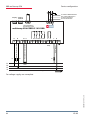
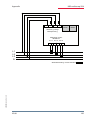
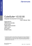
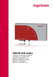
2.2
Connection chart
zu weiteren Busteilnehmern
bzw. Leitungsabschluss /
to other bus devices
and line termination
Display Modul/
Module
OUT
51 52
OUT
92 91 90
- +
B
A
Temperaturfühler /
temperature probe
multicomp 5D6-ESBSDS-1V1C6RO
C
S
L
N
30 31
1
2 PE
Stufen / Stages
Relais /
Relay
Netz / power
C K1 K2 K3 K4 K5
40 41 42 43 44 45
Hauptstrom / main current
k1 l1
20 21
F1
Stromflußrichtung / current direction
h Caution
The coil voltage for the capacitor contactors and the measuring voltage have to
be drawn from the same phase, as only the measuring voltage is monitored (to
protect the contactors from direct resetting in case of short-term monophase
power failure).
12
V5.00
EDEBDA0204-4514-1_EN
L1
L2
L3
N
N
13
Messspannung / Measuring voltage
F1
L1
10
Installation
2.3
KBR multicomp 5D6
Terminal assignment
Terminal
1 (L) and 2 (N):
Power supply connection
A control voltage is required to supply the device with power.
The unit is equipped with a multi range power supply and may
be supplied by voltages of 85 – 265V AC/DC (see nameplate for
device voltage).
10 (L1,Lx):
13 (N,Ly):
Measuring input for voltage
Voltage measurement both as PH-N and PH-PH measurement.
Direct measurement for 100... 500...600V AC. Measuring ranges
are configurable. Exceeding the measuring range results in an
error message.
For higher voltages, connection via a voltage transformer is
necessary (medium voltage measurement x/100 V), with a
measuring range from 500V to 30.0 KV Ph-Ph.
20 (k1) and 21 (l1)
Measuring input for current
The measuring input for current must be connected via a
current transformer x/1A AC or x/5A AC.
When connecting the transformer, pay attention to the energy
flow direction and to the correct assignment of measuring
voltage input to the current transformer.
30 (C) and 31 (S):
Floating relay contact
This contact serves as a message or alarm output. During
operation, an acoustic signal or visual message may be
activated, or a consumer shut down. The contact is open as
long as the device is de-energized and if a message is active.
Maximum switching capacity of 2A at 250V AC
40 (C):
Connection for voltage supply to the relay output terminals
41 to 45
EDEBDA0204-4514-1_EN
The relays for the control outputs share the same connection to
the supply voltage.
V5.00
13
Installation
KBR multicomp 5D6
Terminal:
41 (K1) to 45 (K5):
Floating relay contacts
These contacts are used as control outputs for the capacitor
contactors. The contacts are opened if the device is deenergized and for stages not hooked up. Maximum switching
capacity of 2A at 250V AC
51 (-) and 52 (+):
Temperature sensor input
A temperature sensor, e.g. PT1000, can be connected to this
input to measure the switchgear cabinet temperature.
Temperature measuring range of – 20°C to 100°C +/- 2°C.
90 (earth):
91 (A)
92 (B)
2.4 Interface connection
For communication on the eBus or Modbus
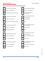
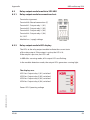
Inserting or replacing backup battery
The device is equipped with an internal data memory, which is battery buffered
to preserve long-term data. To prevent it from being discharged, the backup
battery (e.g. Varta CR 2032) is not built in when the device is delivered, but
included separately in the delivery.
h Caution
Before initial start-up of the device, please insert the backup battery (as
described in the following), as otherwise, all stored data would be lost in case of
a power failure.
1. Disconnect the device from the supply voltage.
2. Lift the upper housing cover with a suitable tool
(e.g. a small screwdriver).
EDEBDA0204-4514-1_EN
3. When replacing a battery, remove the empty battery from the clamping
bracket with the tool.
4. Push the new battery into the clamping bracket and make sure that it is
inserted correctly and has the right polarity.
14
V5.00
Installation
KBR multicomp 5D6
5. Put the upper housing cover back on and click it into place by pushing.
6. Reconnect the device to the supply voltage.
h Caution
As, when the battery is empty or removed and there is no supply voltage, not
only the storage data are lost but the time is not correct anymore either, the
time has to be reset in visual energy with the corresponding command!
h Caution
EDEBDA0204-4514-1_EN
To prevent short circuits, it is recommended to use an insulated screwdriver!
V5.00
15
KBR multicomp 5D6
Commissioning
3Commissioning guideline for the
multicomp 5D6
This guideline helps you to correctly start up the multicomp 5D6
compensation controller. It provides you with step-by-step instructions to help
you find the options relevant for you within the manual.
To begin with, there are two cases in which the commissioning procedure for
the multicomp 5D6 differs.
Case 1: You have bought a complete compensation system from KBR, with
the controller already installed. If this is the case, certain settings are already
preconfigured in the controller.
Case 2: You only bought the controller, or the controller with additional
modules (multisio 2D2-1T2RO, multisio 2D2-4RO, multisio 1D2-4CI
and multimess 1D4) and individual capacitor stages, but the device is not
assembled. In this case, the controller is delivered with the default settings
(refer to chapter Default settings) and has thus not been preconfigured.
3.1
Controller not preconfigured
If a controller not configured is to be commissioned, the following procedure
has to be performed step by step.
1. Configuring additional modules (multisio 2D2-1T2RO, multisio 2D24RO, multisio 1D2-4CI and multimess 1D4)
If there are no additional temperature, relay or induced current measuring
modules, this step can be skipped. To configure additional modules, connect
them and the supplied bus line to the basic module. The additional modules
can then be activated individually in scan mode, which has to be triggered via
the basic module's operating panel and the DIP switches or scan buttons on the
additional module. If the compensation system controls several cabinets, the
correct cabinet assignment has to be set up.
2. Configuring current transformer values
For the compensation controller to function properly, all current transformer
parameters have to be set correctly. Primary and secondary current of the
transformer have to be set. These parameters can be read on the nameplate of
the current transformer. In addition, the phase allocation of the transformer has
16
V5.00
EDEBDA0204-4514-1_EN
Detailed instructions for this step are given in chapter Settings under Submenu
Modules / display.
Commissioning
KBR multicomp 5D6
to be set correctly. This means that the phase (L1, L2, L3) in which the current
transformer is integrated has to be set up in the controller.
Detailed instructions for this step as well as additional information on this topic
are given in chapter Commissioning under Submenu Transformer settings.
3. Setting target cosine:
For information on the target cosine to be set up at this point, contact your
energy supplier. The target cosine is by default set to 0.95 inductive (see
chapter Default settings).
Detailed instructions for this step as well as additional information on this topic
are given in chapter Commissioning under Submenu Target cosine.
4. Configuring the capacitor stages
There are two ways of configuring the capacitor stages. The stages can be
configured manually or using the auto configuration mode (a connected
current measuring module is required).
The most important setting to pay attention to is the stage power. The stage
power can be looked up on the nameplate of the stage or the circuit diagram
and then programmed manually. The auto configuration mode automatically
sets this value. However, the value has to be checked and confirmed each time
the auto configuration mode is applied.
Detailed instructions for the auto configuration mode are given in chapter Extra
, Commissioning , Stages , Stage , Auto configuration mode.
After the stage power has been configured, you have to set the detuning factor.
This factor can be read on the circuit diagram cover sheet or the nameplate of
the stage.
If the compensation system consists of several cabinets, the cabinet assignment
should be adjusted accordingly.
Detailed instructions for this step are given in chapter Commissioning under
Submenu Stages.
EDEBDA0204-4514-1_EN
5. Function test
After all values have been configured, a function test should be performed. To
do so, the controller has to be taken off the voltage supply for a few seconds.
After re-connecting it to the voltage supply, the controller has to start
automatically. If the cosφ voltage is read out in the cosφ momentary menu
immediately after switching it on, the value for cosφ should be low and
V5.00
17
KBR multicomp 5D6
Commissioning
inductive. After approx. 180 seconds, the controller starts switching on the
individual capacitor stages.
The cosφ, which can be read out in the cosφ momentary menu, should have
risen in comparison with former values, or it should rise when switching on
additional stages. If the compensation unit is dimensioned correctly, the
controller should compensate the set target cosine after a certain period of
time.
3.2
Controller not preconfigured
If a controller already integrated into a KBR compensation unit by default is to
be used, only the parameters of the current transformer have to be configured.
1. Configuring current transformer values
For the compensation controller to function properly, all current transformer
parameters have to be set correctly. Primary and secondary current of the
transformer have to be set. These parameters can be read on the nameplate of
the current transformer. In addition, the phase allocation of the transformer has
to be set correctly. This means that the phase (L1, L2, L3) in which the current
transformer is integrated has to be set up in the controller.
Detailed instructions for this step and additional information on this topic are
given in chapter Commissioning under Submenu Transformer settings.
2. Function test
After all values have been configured, a function test should be performed. To
do so, the controller has to be taken off the voltage supply for a few seconds.
The cosφ, which can be read out in the cosφ momentary menu, should have
risen in comparison with former values, or it should rise when switching on
additional stages. If the compensation unit is dimensioned correctly, the
controller should compensate the set target cosine after a certain period of
time.
18
V5.00
EDEBDA0204-4514-1_EN
After re-connecting it to the voltage supply, the controller has to start
automatically. If the cosφ voltage is read out in the cosφ momentary menu
immediately after switching it on, the value for cosφ should be low and
inductive. After approx. 180 seconds, the controller starts switching on the
individual capacitor stages.
Commissioning
KBR multicomp 5D6
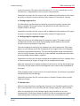
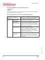
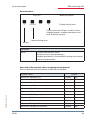
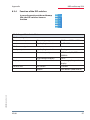
IMPORTANT SAFETY INFORMATION
Caution
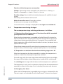
For the following programmed stage powers, the discharge times are
automatically predefined. However, these must be checked and corrected if
they differ from the capacitor specifications.
Discharge resistance
Discharge time
2.5 kvar–7.5 kvar
300 kOhm
60 seconds
10 kvar–17.5 kvar
300 kOhm
120 seconds
20 kvar and over
300 kOhm
180 seconds
EDEBDA0204-4514-1_EN
Capacitor power
V5.00
19
Range of functions
KBR multicomp 5D6
4Functions of the controller in the secureC
safety and maintenance concept
h Caution
These functions are available with the current measuring module multisio 1D24CI and the energy measuring module multimess 1D4!
Information on password protection of secureC can be found in chapter
5.13.2.3 Service submenu.
4.1
Stage resonance frequency monitoring
A stage is only locked from further use if it enters the critical range (resonance
frequency) due to loss of capacitance. In the display, the respective stage will
be identified by an X.
h Caution
You can unlock the stage in the submenu Mode of the Stage administration
menu.
If the stage is locked (due to loss of capacitance), do NOT activate the learning
mode but exchange the defective capacitor!
1. Evaluating the resonance frequency:
a) Detuning 5.5%, 7% or 8% (5th harmonic is critical) If the resonance
frequency is below 111% of the 5th harmonic, the warning threshold is
exceeded.
If the resonance frequency is below 107% of the 5th harmonic, the alarm
threshold is exceeded.
b) Detuning 12.5% or 14% (3rd harmonic is critical) If the resonance
frequency is below 104% of the 3rd harmonic, the warning threshold is
exceeded.
20
EDEBDA0204-4514-1_EN
If the resonance frequency is below 103 % of the 3rd harmonic, the alarm
threshold is exceeded.
V5.00
Range of functions
KBR multicomp 5D6
When the
warning threshold is exceeded, a message (E28 Capacitance loss) is displayed
(warning threshold if induced current approx. 35% too low)
alarm threshold is exceeded, a message (E28 Capacitance loss) is displayed
(alarm threshold if induced current approx. 45% too low)
If loss of capacitance can still be detected after five more attempts at switching
on a stage, the respective stage is locked from further connection and the
message E30 Stage locked is displayed.
4.2
Current consumption and performance monitoring of stages
h Caution
Monitoring is only performed when switching on or off additional stages!
If a stage is detected to be defective (E26 Capacitor current too high or E
28 Capacitance loss (capacitor current too low) ), a message is displayed.
Limiting condition is the stage pattern of the stages created.
The error message E27 check fuse is displayed if the current consumption
of the system (the cabinet in which the measurement is performed) does not
change when a stage is switched on.
If the value does not change when a stage is switched off, the message E29
Contactor defective (stuck) is displayed.
4.3Current consumption and performance monitoring of complete
cabinets
Current consumption monitoring of individual cabinets is an important safety
function.
EDEBDA0204-4514-1_EN
The current consumption is measured in the cabinet, with a multisio 1D2-4CI
current measuring module or a multimess 1D4 energy measuring module.
Each cabinet is monitored individually. Current consumption values which are
too high or too low are taken into account.
V5.00
21
Range of functions
KBR multicomp 5D6
Function with too high power consumption:
The cabinet is permanently monitored. The intervals between the
measurements vary according to the number of connected modules
(measurement intervals: 50 to 500 ms).
If the power consumption in a cabinet is too high, the stages in this cabinet
are switched off one after the other until either all stages in the cabinet are
switched off or the power consumption is within limits again.
Settings:
The settings can be changed in the menu Extra => Settings => System =>
Parameters => Limits => Lim U => Lim +Ie.
Possible settings:
Permissible limit violation between 110% and 200% of rated current
Monitoring of limit violation active or off
Action in case of an error:
Only alarm relay switches
Only the compensation stages are switched off
The alarm relay switches and the compensation stages are switched off
No action, just a message via KBR eBus
In case of an error, an additional message is displayed on the LCD.
Example: E31 Lim le violated, cabinet No.: 2
For 3-phase induced current monitoring, a current measuring module is
required for each cabinet.
Using monophase induced current monitoring, one current measuring
module can be used to monitor 4 cabinets. In this case, the cabinet
assignment of the current measuring module is equivalent to the first input of
the current measuring module.
Example: Current measuring module assigned to cabinet 1:
Input 1
=
cabinet 1
Input 2
=
cabinet 2etc.
22
Current measuring module assigned to cabinet 2:
Input 1
=
cabinet 2
Input 2
=
cabinet 3etc.
EDEBDA0204-4514-1_EN
V5.00
Range of functions
KBR multicomp 5D6
Function with too low power consumption:
Settings: The settings can be changed in the menu Extra => Settings =>
System => Parameters => Limits => Lim U => Lim +Ie.
Possible settings: Permissible limit violation between 0% and 90% of rated
current
Monitoring of limit violation active or off
Action in case of an error: Alarm relay switches
No action, just a message via the KBR eBus
In case of an error, a message is displayed but no stages are switched off.
4.4
Temperature monitoring of stages
The overtemperature stage switching performance is as follows:
1.) Reducing the cabinet temperature if the alarm threshold is exceeded
(prerequisite: at least 2 cabinets)
When the alarm temperature is exceeded and a dwell time of 3 minutes has
elapsed, the device tries to replace the stage with an equivalent stage (same
stage power, detuning and type (thyristor / contactor) ) from a cabinet with
lower temperature. After a dwell time of another 3 minutes, the device tries to
replace the next stage.
If the cabinet temperature falls under the alarm temperature (not yet below
hysteresis limit), no further stage is replaced. (the hysteresis is not working!)
2.) Temperature as selection criterion when switching stages on or off
If the alarm temperature has been exceeded in a cabinet, the temperature is
used as a criterion for selecting the stage to be switched.
If several stages with the same stage power and detuning factor are available,
the stage with the higher cabinet temperature is preferred for switching off.
For switching on, the stage with the lowest cabinet temperature is preferred.
EDEBDA0204-4514-1_EN
The temperature is only used as a selection criterion if the alarm temperature is
exceeded, as otherwise the stage "circuit switching" does not work anymore.
3.) Emergency shut-down
If the switch-off temperature is exceeded, only one stage is switched off at first.
The next stage is not switched off until a dwell time of 2 minutes has elapsed.
V5.00
23
KBR multicomp 5D6
Range of functions
If the temperature falls below the switch-off temperature (not yet below
hysteresis), no other stages are switched off. On the other hand, no stages of
this cabinet are switched on as long as the temperature does not fall below the
hysteresis threshold.
As soon as the temperature falls below the hysteresis threshold, the stages in
this cabinet are released for compensation.
The default settings are:
Operating point fan = 28 °C / hysteresis = 5 °C
Operating point alarm = 45°C / hysteresis = 5 °C
Operating point overtemperature = 50 °C / hysteresis = 5°C
This means that the fan switches on when 28°C are exceeded and switches off
again when the temperature drops below 23°C. The overtemperature alarm is
triggered when 45°C are exceeded and is reset when the temperature drops
below 40°C. The overtemperature stage switch-off is activated when 48 °C are
exceeded. After the temperature has dropped below 43 °C, the stages are, if
required, hooked up again after the discharge time has elapsed.
EDEBDA0204-4514-1_EN
The overtemperature switch-offs for the individual stages are added together
for subsequent determination whether there are temperature problems and, if
so, in which cabinet.
24
V5.00
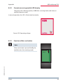
System operation
5
KBR multicomp 5D6
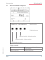
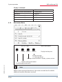
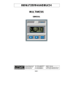
Control and display panel
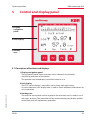
1 Display
navigation
panel
2 Unit display
3 Hot key
area
5.1 Description of buttons and displays
1 Display navigation panel
The navigation panel shows the main menu selected, considerably
simplifying operation of the device.
The operator can immediately see which menu he is in.
2 Unit display
The DOT matrix display is normally used to show measured values.
In some submenus, this display area is used to show additional information to
assist operation.
EDEBDA0204-4514-1_EN
3 Hot key area
The text line corresponds to the respective function keys and is used to issue
messages and text. The interaction of key and accompanying display enables
convenient and self-explanatory operation.
V5.00
25
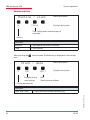
26
EDEBDA0204-4514-1_EN
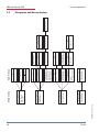
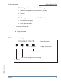
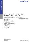
Module management
Module display Basic
Cabinet allocation
Temperature
Temperature cabinet 1
Fan status cabinet 1
U/I
Voltage U
Primary current I
Module management
Additional module types
Cabinet allocation
Max
Maximum values
Cabinets 2 to 6
Temperature
Temperature cabinets
2 to 6
Fan status cabinets 2 to 6
Mom
Momentary values
Max
Maximum values
OTemp
Overtemperature
switch-offs cabinets 2 to 6
Induced current
Induced current cabinet 1
Ie / f
Induced current
U PH-N momentary value
Reactive power Q1
Network frequency
OTemp
Overtemperature
switch-offs cabinet 1
Min
Minimum values
Max
Maximum values
SPQ
Total power
Max
Max. values
Additional stages
Target
Curr. target Cos Phi
Max
Max. values
Sub menus
Mom
Momentary values
Cabinets 2 to 6
Freq.
Network frequency
Induced current
Induced current cabinets
2 to 6
Max
Maximum values
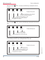
5.2
Cos Phi
Mom. Cos Phi
Mom. missing
Comp. power
Main menu
KBR multicomp 5D6
System operation
Navigation and device displays
V5.00
EDEBDA0204-4514-1_EN
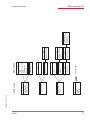
V5.00
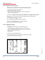
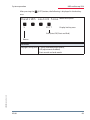
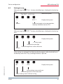
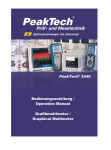
Extra
Commissioning
Settings
Messages
Harmon I
Harmon. I total
Cabinet 1
Harmon. U
Harmon. U total HD
Stages
Stage power stage 1
Operating cycles
Overtemp. switch-offs
Main menu
Harmon I
Harmon. I 3th to 19th
Cabinets 2 to 6
Harmon I
Harmon. I total
Cabinets 2 to 6
See next page
Max
Maximum values
Harmon. I 3th to 19th
Cabinet 1
Max
Maximum values
Harmon. U 3rd to 19th
Harmon I
Harmon. I 3th to 19th
Cabinet 1
Max
Maximum values I tot.
Cabinet 1
Harmon U
Harmon. U 3rd to 19th
Max
Maximum values U HD
Mode
Stage automatic, off, on
Stages
Stage power stages
2 to 26
Operating cycles stages
2 to 26
Overtemperature
switch-offs
Sub menus
Max
Maximum values
Harmon. I 3th to 19th
Cabinets 2 to 6
System operation
KBR multicomp 5D6
27
28
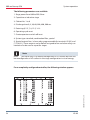
Extra
Next
Commissioning
Settings
Messages
EDEBDA0204-4514-1_EN
F1
F2
F3
F4
F1
F2
F3
F4
F1
F2
F3
F4
Settings
Back
Modules / display
System
Service
Target cosine
Cos 1st to 3rd setting
F1
F2
F3
F4
Modules / display
Back
Module management
Bus parameters
Display / language
Special
Combination filter
Stages
F1 Back
F2 Auto configuration
mode
F3 Stage parameters
F4 Rated voltage
Type of system:
Standard
Jump acc. to system type
Commissioning
Back
Transformer
Target cosine
Stages
Transformer
F1 Back
F2 Main current
transformer
F3 Induced current
transformer
F4 Voltage transformer
F1
F2
F3
F4
Language
Display / language
Back
LCD parameters
Language
Runtime / clock
Runtime / clock
LCD parameters
Bus
Module scan
Delete module
Assign cabinet No.
Module detection on/off
Discharge time
Discharge time
Stage parameters
Stage power
Detuning
Cabinet No.
Module management
Discharge time/detuning
Discharge time
Detuning 1
Detuning 2
Discharge time/detuning
Discharge time
Detuning
Stage parameters
Stage power
Detuning
Cabinet No.
Stage parameters
Stage power
Cabinet No.
Auto configuration mode
F1 Back
F2 Start
F3
F4
Voltage transformer
U primary
U secondary
Phase U
Zero-point creator
F1 Back
Ie primary
Ie secondary
Mode
Induced current transformer
Main current transformer
I primary
I secondary
Phase I
Clock / date
Firmware display
Operating cycles
Operating cycles
Number of overtemp.
switch-offs
Reset
Setting per stage
Daylight saving time
System type
System type
Special outputs
Fan
Alarm relay
KBR multicomp 5D6
System operation
V5.00
F1
F2
F3
F4
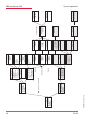
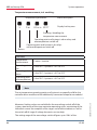
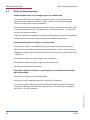
Extra
Back
Commissioning
Settings
Messages
EDEBDA0204-4514-1_EN
V5.00
Settings
Back
Modules / display
System
Service
Messages
F1 Back
F2 Curr. error messages
F3 Error status
F4 Relay / stage
switch-off
F1
F2
F3
F4
Service
Back
Hotline
Password
Firmware version
Relay / stage switch-off
Allocation message /
Relay / switch-off
Curr. Error messages
F1
F2
F3
F4
System
F1 Back
F2 Parameter
F3 Reset
Serial No.
Firmware display
Password
Firmware version
Error state
Reset ( 1 )
Reset limits
Reset extreme values
Back
LIM U
LIM operating cycles
LIM harmon. U
Reset ( 2 )
Reset stage parameters
Reset module
parameters
LIM harmon. U
Type (exceeded)
Output (alarm relay/
stage switch-off)
LIM U
Type (exceeded)
Output (relay/switch-off)
LIM Ie+ / Ie-
Limits
F1
F2
F3
F4
Temp. fan
Switching threshold
Hysteresis
Attenuation coefficients
Voltage
Current
Q fehl
Switching hysteresis
Hysteresis On (%)
Hysteresis Off (%)
Temperature parameters
Measurement activated /
deactivated
Hotline
Reset
Activation
Commissioning status
Reset error status
Reset para. Current
transformer
Parameter
F1 Back
F2 Switching performance
F3 Temperature
parameters
F4 Limits
Switching performance
F1 Back
F2 Switching hysteresis
F3 Switching times
F4 Attenuation coefficients
Reset ( 3 )
Reset to default settings
Reset measuring
parameters
LIM operating cycles
Lim Ie+ / IeType exceeded
Type underrange
Output (relay/switch-off)
Temp. switch-off
Switching threshold
Hysteresis
Temp. alarm
Switching threshold
Hysteresis
Switching times
t idle (s)
t alarm (s)
Switching interval
System operation
KBR multicomp 5D6
29
KBR multicomp 5D6
System operation
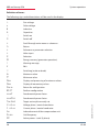
Definition of terms:
The following signs and abbreviations will be used in the display:
Star voltage
4
Delta voltage
Inductive
Capacitive
Switch on
Switch off
Scroll through main menu or submenu
Return
Submenu or parameter selection
Value input
Selection
a
Energy recovery (generator operation)
b
Warning message
d
Switching (make or break)
e
Maximum value
f
Minimum value
Max
Display and processing of maximum values
Mom
Display of momentary values
Para
Return for configuration
EDIT
Perform configuration
cos
Fundamental power factor
cosPhi
Fundamental power factor
Target
Target cosine phi currently set
U ph-n
Voltage phase / neutral conductor
I ph-n
Current phase / neutral conductor
le
Induced current of the compensation unit
Freq
Grid frequency
P
Active power – total (3-phase)
30
EDEBDA0204-4514-1_EN
cEdit
V5.00
System operation
KBR multicomp 5D6
SPQ
Apparent power / active power / reactive power - total (3-phase)
Harm. U
Voltage harmonics (distortion factor)
Harm. I
Current harmonics (distortion current strength)
Lim
Limit value
DF
Attenuation coefficient
Module
Module management
YES
Confirmation to save configuration
NO
Discard configuration
SCANScan mode (search mode) for module search and eBus address
assignment
Mode
Switching mode of stages
Firmware
Operating software of the measuring module or display module
Setup
Device configuration
Mess.
Error messages and error state
Displ.
Operating system of display module
1ph
monophase (for induced current measurement)
3ph
three-phase (for induced current measurement)
EDEBDA0204-4514-1_EN
Basic para Basic parameters (submenus)
S
Expansion cabinets 2 to 6
ÈÉÊU
Measuring voltage transformer prim./sec.
ÈÉÊI
Main current transformer prim./sec.
Learn
Learning function stage power
Bus
Bus parameters
LCD
LCD parameters (display module)
Dfact
Attenuation coefficient (switching interval stages)
Lan.
Language of text display (display module)
Code
Password protection
Reset
Reset function extreme values and configuration
Temp
Enable temperature measurement
Serv Customer service address
V5.00
31
System operation
KBR multicomp 5D6
Operating messages for individual switching stages:
1
= switching stage number
1
= switching stage number
= stage is switched off
= stage is switched off
A
= in automatic operation mode
= and no stage power
configured
1
A
= switching stage number
= no compensation stage
(other mode)
= stage is switched on
= switched off
1
= switching stage number
= in automatic operation mode
= stage is switched off
F
= fan
= no compensation stage
(other mode)
F
= switched on
O
= in manual operation
1
H
= switching stage number
= no compensation stage
(other mode)
= stage is switched on
= not switched (no fault)
1
= switching stage number
= in manual operation
= stage is switched off
= and not available
= alarm relay
= no compensation stage
(other mode)
E
= switched, i.e. fault exists
= alarm relay
EDEBDA0204-4514-1_EN
X
E
= fan
32
V5.00
System operation
KBR multicomp 5D6
Settings:
Damping (DC)
=Reduction of the display fluctuations;
the measuring cycle of the controller is not influenced
Idle time (t-idle)
= Starts at compensation; after the idle time has expired,
the next switching action follows
Alarm delay (t-alarm)
=Concerns the FTS message ("facility too small"),
i.e. all stages are hooked up, but the set alarm CosPhi
is not reached. After the set time has expired, an alarm
message is issued
Hysteresis (Hyst.)
= Refers to the smallest available stage power
and the overcompensation or undercompensation, i.e.
the hooking up or switching off starts at the percentage
set
Switch damping
= The time set defines the interval between two
switching actions.
Operating cycle limit
= When the set value is reached, a message
is issued. This value is based on the details from the
contactor manufacturer.
Switch-off threshold (Lim-U) =Overvoltage switch-off to protect the facility, i.e.
switching off the stages starts when the set limiting
value is exceeded (hysteresis = 1% of the measurement
voltage)
Switch-off threshold
LIM Ie +
=Undercurrent limiting value in induced current
measurement
EDEBDA0204-4514-1_EN
Switch-off threshold
LIM Ie -
=Overcurrent limiting value in induced current
measurement
V5.00
33
KBR multicomp 5D6
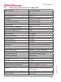
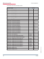
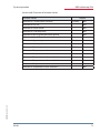
Setting range of the parameters configurable:
Primary voltage
Secondary voltage
Primary current
Secondary current
Rotary field U
Rotary field I
Consumption target cosφ
Recovery target cosφ
FTS alarm cosφ
Current attenuation coefficient
Voltage attenuation coefficient
Attenuation coefficient Qmiss
Idle time
Alarm relay time
Hysteresis connection
Hysteresis disconnection
Switching interval
Operating cycle limit
Cabinet No.
Stage power
Discharge time
Detuning
Stage switching mode
Harmonics monitoring
Overvoltage switch-off
Overcurrent switch-off
Undercurrent switch-off
THD limit
Operating point fan
Operating point alarm
Operating point overtemperature
Scanning frequency
Password
1 V to 9999 kV Ph-Ph
100 V to 500 V Ph-Ph
1 A to 99.99 kA
1 and 5 A
L1N, L2N, L3N, L12, L23, L31
L1, L2, L3, -L1, -L2, -L3
ind. 0.80 to cap. 0.80
ind. 0.80 to cap. 0.80
ind. 0.50 to cap. 0.50
0 to 6
0 to 6
0 to 6
0 to 300 sec.
0 to 3000 sec.
70 to 150 %
70 to 150 %
0 to 10 sec.
0 to 99990
1 to 6
0 bis 999.9 kvar inductive or capacitive
0 to 900 sec.
0, 5.5, 7, 8, 12.5, 14 %
Automatic, manual off, manual on
0 to 99%, deactivatable
dependent on primary voltage
110% to 200%
0 to 90%
0 to 10%
0 to 70°C / hysteresis = 0°C to 25°C
0 to 70°C / hysteresis = 0°C to 25°C
0 to 70°C / hysteresis = 0°C to 25°C
Automatic, fixed 50 Hz, fixed 60 Hz
No password (9999, meaning all functions
are accessible)
Language display
Contrast setting
German / English
60% to 100%
34
V5.00
EDEBDA0204-4514-1_EN
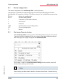
5.3 System operation
System operation
5.4
KBR multicomp 5D6
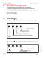
Device configuration
The menu navigation of the multicomp 5D6 is self-explanatory.
The operator is guided and supported by the device through operating instructions
displayed for the respective situation. The following terms are available for programming:
Para
Return for configuration
EDIT
Perform configuration
Submenu or parameter selection
+
Value input
Selection
YES Confirmation to save configuration
NO Discard configuration
¡Return
5.5
Start menu Commissioning
If the multicomp 5D6 is being commissioned for the first time, the menu Extra
/ Commissioning is displayed as the start screen (after the initialization phase)
after setting up the supply voltage for the multicomp 5D6.
EDEBDA0204-4514-1_EN
This display is used for the Initial commissioning of the controller, where all
the necessary settings can be made.
i Note
These settings are described in detail in the menu item Extra / Commissioning
V5.00
35
KBR multicomp 5D6
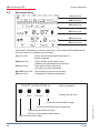
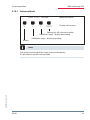
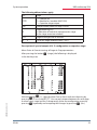
5.6
System operation
Main menu Cosφ
1st menu line
2nd menu line
3rd menu line
4th menu line
5th menu line
6th menu line
The display is divided into various menu lines. The number of lines depends on
the main menu or submenu item selected:
1st menu line:Shows which of the eight main menus is
being displayed
2nd menu line:Status display of the output lines;
modules are identified by vertical lines
3rd menu line:Description of the menu and
messages currently displayed
4th+5th menu line: Value display for the current menu
6th menu line:
Navigation in the menu displayed
Cos momentary
Max
Target
Menu description
Display hot key area
Continue with additional stages
EDEBDA0204-4514-1_EN
Display of the momentary target cosφ
Display of the maximum value
of the missing compensation power
Scroll through main menu
36
V5.00
System operation
KBR multicomp 5D6
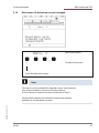
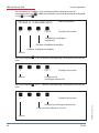
Display as example:
Main menu:
= cosφ momentary
Stage switching mode:
= Stage 1 manual mode on
Stages 2 to 12 automatic mode on
Stages 13 to 16 automatic mode off
Fan:
= on
Alarm relay:
= on
Error message:
= exists ()
Menu description:
= cosφ momentary
Measured cosφ:
= 0.87 inductive
Switching on / off:
= Switching on,
since capacitor power is missing
Missing
compensation power
= 57.0 kvar
Additional modules
= existing ()
By pressing the button, you can display the maximum value of the
missing compensation power.
The value is displayed in kvar, with time and date stamp. The value is only
displayed if all available stages are switched on and the configured alarm
CosPhi is not reached when the set alarm delay time has elapsed.
The respective value is a maximum value (maximum indicator function)
accumulated during the alarm delay time.
As soon as the value is entered, the status message
E12 facility too small is displayed in the Messages submenu with a time
stamp and kvar specification.
i Note
EDEBDA0204-4514-1_EN
The value displayed here is the mean value of the set alarm delay time. I.e.
this value and the maximum value of the missing compensation power can
be different.
V5.00
37
System operation
KBR multicomp 5D6
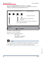
After pressing the () button, the following is displayed
in the hot key area:
Display as example:
Main menu:
= cosφ momentary
Stage switching mode:
= Stages 17 to 24 automatic mode on
Fan:
= on
Alarm relay:
= on
Error message:
= exists ()
Menu description:
= cosφ momentary
Measured cosφ:
= 0.87 inductive
Switching on / off:
= Switching on,
since capacitor power is missing
Missing
compensation power
Note
This window is only displayed if more than three additional relay modules are
scanned (which can be seen from the button designation over )
38
V5.00
EDEBDA0204-4514-1_EN
i = 57.0 kvar
System operation
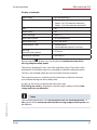
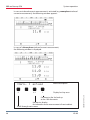
5.7
KBR multicomp 5D6
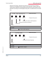
Main menu Voltage / current
U, I momentary
Max
SPQ
Ii/f
Menu description
Display hot key area
Display of induced current, grid
frequency, grid frequency maximum
value, mom. voltage in the cabinet,
reactive power of switched stages
Totals for three-phase apparent, active and reactive
power, minimum and maximum values
Display and processing for maximum values U/I
Scroll through main menu
EDEBDA0204-4514-1_EN
Display as example:
V5.00
Phase voltage
= 231 V
Apparent current monophase
= 152 A
39
System operation
KBR multicomp 5D6
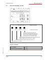
5.8
Main menu Temperature
Temperature
Cabinet No. 1
Max
oTemp
Menu description
Display hot key area
Submenu
Temperature modules 1 to 3
Display of overtemperature switch-offs, sorted by
cabinet
Display and processing for
maximum values, sorted by cabinet
Scroll through main menu
40
Cabinet No.:
=1
Temperature measured
= 31.4 °C
Fan status:
= switched on
EDEBDA0204-4514-1_EN
Display as example:
V5.00
System operation
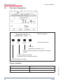
5.9
KBR multicomp 5D6
Main menu Module management
Module management
Menu description
Display hot key area
Additional modules - display descending
Additional modules - display ascending
Scroll through main menu
EDEBDA0204-4514-1_EN
Display as example:
V5.00
Module:
= Temperature module controller
(basic module)
Cabinet assignment:
= fitted in cabinet No. 1
41
System operation
KBR multicomp 5D6
5.10
Main menu Stages
stage 01
Menu description
K1
Mode
Display hot key area
Set switch mode of stages (On, Off,
Automatic mode)
Additional stages - display descending
Additional stages - display ascending
Scroll through main menu
42
Stage No. and
connection terminal:
= Stage 01, terminal K1 at the basic
module (for the 1st additional module,
the description would be terminal M1K1)
Stage type:
= capacitor stage
Stage power:
= 10 kvar
Operating cycles:
= 21
Overtemperature switch-offs:
=3
V5.00
EDEBDA0204-4514-1_EN
Display as example:
System operation
KBR multicomp 5D6
5.10.1 Submenu Mode
Switch mode
EDIT
Menu description
Display hot key area
Editing (on, off, automatic mode)
Additional stages - display descending
Additional stages - display ascending
Return
i Note
EDEBDA0204-4514-1_EN
Due to the monitoring of the stage resonance frequency,
it is possible to use the Locking mode.
V5.00
43
System operation
KBR multicomp 5D6
5.11
Main menu U h voltage distortion factor
Harm. U actual
Menu description
Display hot key area
Max
Continue to the 3rd and up
to the 19th harmonic
Display and processing for maximum values
Scroll through main menu
Display as example:
= 0.7%
EDEBDA0204-4514-1_EN
Total harmonics of measuring
voltage :
44
V5.00
System operation
5.12
KBR multicomp 5D6
Main menu I h distortion current strength
Harm. I
Menu description
Display hot key area
Scroll through main menu
i Note
This menu is only available for induced current measurement
(has to be activated in the menu Commissioning
, Transformer , Induced current transformer , Para)!
EDEBDA0204-4514-1_EN
Please check whether the induced current measurement
module has already been scanned.
V5.00
45
System operation
KBR multicomp 5D6
In case an induced current measurement is activated (e.g. monophase induced
current measurement), the following window appears:
Harm. I actual
Menu description
Display hot key area
c
EDEBDA0204-4514-1_EN
In case of a three-phase induced current measurement,
the following window is displayed:
Continue to the 3rd and up
to the 19th harmonic
Harmonics display
for induced current measurement of next cabinet
Scroll through main menu
46
V5.00
System operation
KBR multicomp 5D6
Display as example:
5.13
Cabinet No.:
= S1
Induced current measurement:
= three-phase
Harmonic
= total Id
Harmonic current L1:
= 11 A
Harmonic current L2:
= 11 A
Harmonic current L3:
= 11 A
Main menu Extra
Extras
Comm. Sett. Mess.
Menu description
Display hot key area
Display message
( ! = message exists)
Settings communication / display, system, service
EDEBDA0204-4514-1_EN
Commissioning parameters
Scroll through main menu
i Note
Before commissioning of the device, it has to be ensured that all available
additional modules have been scanned!
V5.00
47
System operation
KBR multicomp 5D6
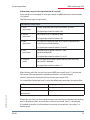
The Commissioning submenu contains the following items:
1. Transformer settings (current, induced current, voltage)
a.
i.
Main current transformer
Primary current
ii. Secondary current
iii. Phase allocation
b.
i.
Induced current transformer
Activate, monophase or three-phase
ii. Primary current cabinet 1
iii. Secondary current cabinet 1
iv. Primary voltage energy measuring module cabinet 1
v.
Secondary voltage energy measuring module cabinet 1
vi. Continue with cabinets 2 to 6
c.
i.
Voltage transformer
Primary voltage
ii. Secondary voltage
iii. Phase allocation
iv. Zero-point creator
2. Target cosine settings
a.
Target cosφ for power consumption
b.
Target cosφ for power recovery
c.
Alarm cosφ for FTS message ("facility too small")
3. Stage settings
a.
Auto configuration mode
b.
Stage parameters
i.
Stage selection
ii. Stage power
iii. Cabinet No.
iv. Discharge time
v. Detuning
EDEBDA0204-4514-1_EN
vi. Operating cycles
vii. Overtemperature switch-offs
viii. System type
ix. Special outputs (fans / alarm relays)
48
c.
Rated values (rated voltage Ph-Ph, grid frequency)
V5.00
System operation
KBR multicomp 5D6
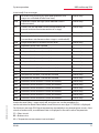
The Settings submenu contains the following items:
1. Module management / bus parameters / display
2. System
3. Service
The Messages submenu contains the following items:
1. Active error messages
2. Error state messages
3. Assignment of message
a. Alarm relay
b. Stage switch-off
5.13.1Commissioning
Commissioning
Cos. stage
Menu description
Display hot key area
Stage settings
cosφ settings
Transformer settings current / voltage
EDEBDA0204-4514-1_EN
Return
V5.00
49
KBR multicomp 5D6
System operation
5.13.1.1Submenu Transformer settings
The Transformer settings submenu contains
the following items:
1. Main current transformer
2. Induced current transformer
3. Voltage transformer
Under the item Main current transformer, the primary and secondary current,
as well as phase allocation of the main current transformer must be specified.
Under the item Induced current transformer, the primary and secondary
current of the induced current transformer must be specified. These settings
have to be individually made for each cabinet! For operation of an energy
measuring module, you can also set the primary voltage and secondary voltage
of the energy measuring module here.
For the item Main current transformer, the primary and secondary current, as
well as phase allocation must be specified. Additionally, you can activate the
zero-point creator here.
The Main current transformer submenu contains the following items:
1. Primary current
2. Secondary current
3. Phase allocation of the main current
For the items Primary current and Secondary current, the respective
parameter for the current transformer must be defined, e.g. transformer
1000/5A stands for a primary current of 1000A and a secondary current of 5A.
The input field ranges from 1A to 99.99kA for a primary current and 1A or 5A for
the secondary current.
For the phase allocation of the main current transformer, the main current
measurement phase must be specified, e.g. phase I = L1. For a false polarity
transformer connection, the input can be given as phase I = -L1 (the minus sign
means that k and l are interchanged).
The Voltage transformer submenu contains the following items:
1. Primary voltage
2. Secondary voltage
3. Phase allocation of measuring voltage
4. Zero-point creator
EDEBDA0204-4514-1_EN
For the items Primary voltage and Secondary voltage, the respective
50
V5.00
System operation
KBR multicomp 5D6
parameter for the voltage transformer must be defined, e.g. transformer
10,000/100V stands for a primary voltage of 10,000V and a secondary voltage
of 100V.
The input field ranges from 1V to 9,999kV for the primary voltage and 100V or
500V for the secondary voltage.
For the item Phase allocation of measuring voltage, the phase of the
measuring voltage must be given, e.g. phase U = L1N.
For a phase/phase measurement, the entry would for instance be L23.
Using the item Zero-point creator, the controller can be activated
via a zero-point creator.
For energy supply networks with outer conductor connected to the
earth potential, suitable control gear with electrical isolation (e.g. voltage
transformer) must be used.
These transducer adapters (zero-point creator) are suitable for creating a virtual
low-impedance neutral point for the device in a three-phase network without
neutral conductor.
In the 700 V variant, this also serves to adapt the measuring voltage to the
device.
Make sure that the device is configured for the operation with a zero-point
creator.
Transformers are available in the following variants:
Version 400/100:
Primary:
400 V phase-to-phase voltage
Secondary: 100 V phase-to-phase voltage
Version 700/100:
Primary:
700 V phase-to-phase voltage
EDEBDA0204-4514-1_EN
Secondary: 100 V phase-to-phase voltage
V5.00
51
KBR multicomp 5D6
System operation
5.13.1.2Submenu Target cosine
The Target cosine submenu contains the following items:
1. Target cosφ for power consumption
2. Target cosφ for power recovery
3. Alarm cosφ (message when alarm cosφ is not reached
after set alarm delay time)
For the items Target cosφ for power consumption and Target cosφ for power
recovery, a value from inductive 0.80 to capacitive 0.80 can be entered.
If active power recovery is detected,
this is signaled by the a symbol in the display.
Under the item Alarm cosφ, a value from inductive
0.50 to capacitive 0.50 can be entered.
5.13.1.3Submenu Stages
The Stages submenu contains the following items:
1. Auto configuration mode (only for use of an induced
current measuring module or energy measuring module.)
2. Stage parameters direct input
3. Rated values
EDEBDA0204-4514-1_EN
In the overview of available stages
(item 2. Stage parameters direct input), the following window
is displayed at initial commissioning:
52
V5.00
System operation
KBR multicomp 5D6
Under the item Auto configuration mode, you can start automatic monitoring
of the connected capacitor stages under the menu item
Extra , Commissioning , Stages , Auto configuration mode , Start.
First, the configured parameters are displayed.
If needed, they can be corrected here or, if they are already correct, confirmed
with (OK). After the last confirmation, all capacitor stages are switched
off, and the auto configuration mode can be started. During the procedure,
the stages are switched on individually, and the stage power is determined.
This can be interrupted by pressing (Stop) at any time. The progress
is illustrated in the status display. Along with this, the connected capacitor
stages are hooked up one after the other. From the current consumption
measured, the multicomp 5D6 determines the corresponding stage power.
After successfully determining the stage power, the result is displayed and
can be saved by confirming it (press button (Return) repeatedly, until
the prompt Save parameters Yes / No appears). If measurement errors have
occurred, they can be discarded, and the mode restarted.
A prerequisite for performing the auto configuration mode
is, however:
1. Measurement via induced current transformer and current measuring
module multisio 1D2-4CI or energy measuring module multimess 1D4
2. Correct configuration of the primary and secondary voltage
3. Correct configuration of the primary and secondary current of the induced
current transformer
4. Correct configuration of the primary and secondary voltage of the energy
measuring module
5. Possible additionally connected relay modules must be detected and stored
with the help of the menu item Settings, Modules / display , Module
management
6. The capacitive or inductive stages have to be connected
EDEBDA0204-4514-1_EN
If all these prerequisites are met, the auto configuration mode of the stage
powers can be started.
Under the item Stage parameters direct input, all stage parameters can also
be entered manually.
V5.00
53
System operation
KBR multicomp 5D6
The following parameters are available:
1. Stage power from 0.00 to 999.9 kvar
2. Capacitive or inductive stage
3. Cabinet No. 1 to 6
4. Discharge time 0, 3, 30, 60, 300, 600, 900 sec.
5. Detuning 0, 5.5, 7, 8, 12.5, 14 %
6. Operating cycle reset
7. Overtemperature switch-off reset
8. System type standard, combination filter, special
9. Special outputs fans / alarm relays programmable for terminals K5 (45) and
C/S (30, 31). These outputs are by default assigned to fan and alarm relay, can
however also be used as capacitor stages.
i Note
Note: The alarm relay is by default configured as a NC contact but can also
be reconfigured as a NO contact in the stage configuration in visual energy.
EDEBDA0204-4514-1_EN
For a completely configured controller, the following window appears:
54
V5.00
System operation
KBR multicomp 5D6
The following abbreviations apply:
St
Stage
CMK
C = Cabinet No.
M = Module No. (module MULTI-RO)
K = Capacitor stage output
Q
Compensation power of stage, in kvar
Stage detuning in %
or indication of inductive compensation stage
(in the stage overview window)
td
Stage discharge time in seconds
Cursor for stage selection with or
Description of special outputs (K5, S) configuration as capacitor stage:
Menu Extra , Commissioning , Stages , Stage parameters:
After pressing the button d (stage), the following is displayed
in the hot key area:
EDEBDA0204-4514-1_EN
With the button (), select the item Fan or Alarm and start the entry by
pressing (Para) and EDIT. You can only choose between fan and stage
or alarm relay, stage and fan. Subsequently, leave the configuration menu by
pressing repeatedly and accepting the changes by pressing (Yes).
V5.00
55
System operation
KBR multicomp 5D6
5.13.2 Settings
Menu description
Settings
Mod.
Syst. Serv.
Display hot key area
Service
System
Module / display
Return
5.13.2.1Submenu Modules / display
The Modules / display submenu contains the following items:
1. Module management
2. Bus parameters
3. Display / Language
Under the item Module management, the additionally connected modules
(relay module multisio 2D2-4RO, temperature module multisio 2D2-1TI2RO,
current measuring module multisio 1D2-4CI and energy measuring module
multimess 1D4) can be scanned, deleted and configured.
EDEBDA0204-4514-1_EN
Description of the module scan:
56
V5.00
System operation
KBR multicomp 5D6
Press the button () to select the entry Scan and start scanning by
pressing (SCAN).
As long as scan is flashing, you can set the first module (and all subsequent
modules to be scanned) into scanning mode using the Scan button on the
modules (see Appendix / Additional modules). The module is then detected
by the controller and allocated to the relevant cabinet.
As soon as all additional modules are read, the scanning mode is to be stopped
by pressing . The list of modules can now be checked for completeness
by pressing the buttons () and (). The cabinet allocation can be
changed with (Para).
EDEBDA0204-4514-1_EN
Display example after module scan:
V5.00
57
System operation
KBR multicomp 5D6
For previously set modules, the switchgear cabinet allocation can be
changed by pressing . Additional modules can be displayed and configured
using () and ().
Module management
Para
Menu description
Display hot key area
Configuring switchgear
cabinet No.
Number of additional modules
Number of additional modules
Return
After pressing the (Para) button, the following is displayed in the hot key
area:
Display hot key area
EDIT
Return
Assignment of
switchgear cabinet No.
After pressing the (EDIT) button, the following is displayed in the hot key
area:
Display hot key area
EDEBDA0204-4514-1_EN
Configuring switchgear cabinet No.
Continue with submenus 3 and 4
Return
58
V5.00
System operation
KBR multicomp 5D6
Submenu 3:Module detection (flashing on and off ). Here, the corresponding
module can be set to flashing mode for unambiguous allocation.
Submenu 4:Module type display and current firmware version of the module.
For example, Temp is entered for the temperature input module, 2.00
as the firmware version and r007 as the firmware version release.
After pressing the (+) button, the following is displayed:
NO
YES
Display hot key area
Enter value
Leave settings menu and save
Leave settings menu without saving
After pressing the or button, the following is displayed:
EDIT
Display hot key area
Assignment of switchgear cabinet No.
Return
i Note
EDEBDA0204-4514-1_EN
Additional modules - see appendix for function of the module DIP switches and
module scan buttons!
V5.00
59
System operation
KBR multicomp 5D6
With the item Bus parameters, bus operation is configured
(KBR eBus and Modbus). Here, the bus address for the KBR eBus and the bus
address and protocol type for the Modbus can be set.
Bus parameters
eBus
EDIT
Menu description
Display hot key area
Selecting the eBus or Modbus bus
protocol
Set bus parameters (address for eBus or address and
protocol type for Modbus)
Return
Parameter
Bus
= eBus or Modbus
Bus address 0 to 9999 for KBR eBus
Bus address 1 to 247 for Modbus
Baud rate and bus protocol on Modbus:
i ASCII or RTU
4800, 9600 or 19200 baud
even, odd or no parity
Note
EDEBDA0204-4514-1_EN
After adjusting the bus type (KBR eBus or Modbus), the controller is restarted,
i.e. all hooked up capacitor stages are discarded and hooked up again.
60
V5.00
System operation
KBR multicomp 5D6
With the item Display / language, the settings for the external LCD display
and the user language German / English can be selected. In addition, the time
setting can be made here and the total operating time for the controller can be
queried. The setting to switch daylight saving time / standard time can be made
here.
LCD parameters
test
dim
EDIT
Menu description
Display hot key area
Settings for contrast and brightness
Settings for dimmer parameters
Display test
Return
Parameter
LCD
= Contrast and brightness
Menu description
Language
EDIT
Display hot key area
setting the display language
Return
Parameter
EDEBDA0204-4514-1_EN
Language
V5.00
= German / English
61
System operation
KBR multicomp 5D6
Runtime and clock:
Runtime / clock
Clock
Menu description
Display hot key area
Time setting and runtime display of
controller
Return
Parameter
Runtime
= Total operating time of controller
Clock
= Time setting
After pressing the (clock) button, the following is displayed in the hot key
area:
Clock / date
DST
EDIT
Daylight saving
time settings
Menu description
Display hot key area
Edit
(Setting time and date)
Display hot key area
Parameter
= Time (hh:mm) and date (dd:mm:yyyy)
EDEBDA0204-4514-1_EN
Clock time / date
62
V5.00
System operation
KBR multicomp 5D6
After pressing the (DST) button, the following is displayed in the hot key
area:
Daylight saving time
EDIT
Menu description
Display hot key area
Edit (Auto/Off, Start and End)
Return
Parameter
Daylight saving time = Auto (automatic adjustment),
Off (adjustment disabled)
EDEBDA0204-4514-1_EN
Start month and end month
V5.00
63
System operation
KBR multicomp 5D6
5.13.2.2Submenu System
The System submenu contains the following items:
1. Parameters
2. Reset
For the item Parameters, the switching performance, temperature parameters
and limiting values can be adjusted.
The switching performance comprises the following options:
Switch-on and switch-off
hysteresis
Input in %, in relation to the stage power of
the smallest available capacitor stage
Switching
times:
Input in seconds (0 to 300 sec.)
Idle time after
compensation
Alarm delay
for FTS message
Input in seconds (3 - 3000 sec.) until the
message Facility Too Small is displayed, i.e.
the alarm cosφ has not been reached after
the set time has elapsed.
Switching interval Input in seconds (0 to 10 sec.).
Here, it is specified at which interval the
capacitor stages must be hooked up if
the compensation power is insufficient to
achieve the set target cosφ.
The attenuation coefficients (0 to 6) serve
for reduction of the display fluctuations;
the measuring cycle of the controller is not
influenced.
EDEBDA0204-4514-1_EN
Attenuation
coefficients
64
V5.00
System operation
KBR multicomp 5D6
The temperature parameters contain the basic enabling and disabling of
the temperature measurement and the switching performance resulting from
this. In addition, the operating point and hysteresis for the fan switch and
the operating point and hysteresis for the overtemperature switch-off can
be set here. The following parameters are available for operating points and
hystereses:
Operating point fan
= 0 to 70°C / hysteresis = 0°C to 25°C
Operating point
alarm
= 0 to 70°C / hysteresis = 0°C to 25°C
Operating point
overtemperature
= 0 to 70°C / hysteresis = 0°C to 25°C
The default settings are:
Operating point fan
= 28°C / hysteresis 5°C
Operating point
alarm
= 45°C / hysteresis 5°C
Operating point
overtemperature
= 48°C / hysteresis 5°C
This means that the fan switches on when 28°C are exceeded and switches off
again when the temperature drops below 23°C. The overtemperature alarm is
triggered when 45°C are exceeded and is reset when the temperature drops
below 40°C. The overtemperature stage switch-off is activated when 48 °C are
exceeded. After the temperature has dropped below 43 °C, the stages are, if
required, hooked up again after the discharge time has elapsed.
EDEBDA0204-4514-1_EN
The overtemperature switch-offs for the individual stages are added together
for subsequent determination whether there are temperature problems and, if
so, in which cabinet.
V5.00
65
System operation
KBR multicomp 5D6
Temperature measurement, incl. enabling:
Temperature parameters
Fan
Alarm EDIT
Menu description
Display hot key area
Enabling / disabling the
temperature measurement
Operating point and hysteresis alarm relays and
overtemperature switch-off
Operating point and hysteresis fan relays
and overtemperature switch-off
Return
Parameter
Temperature
measurement
= active / inactive
Operating point
fan
= 0 to 70°C / hysteresis = 0°C to 25°C
Operating point
alarm
= 0 to 70°C / hysteresis = 0°C to 25°C
Operating point
overtemperature
= 0 to 70°C / hysteresis = 0°C to 25°C
i Note
Moreover, limiting values are available for the overvoltage switch-off of the
system, monitoring of the stage contactor operating cycles, monitoring of the
individual current consumption of the stages and of entire cabinets as well as
the switch-off of stages if voltage harmonics are too high.
The setting range of the overvoltage switch-off goes up to 150% of the
66
V5.00
EDEBDA0204-4514-1_EN
The set temperature operating points and hysteresis are equally valid for the
controller basic module and the additionally connected temperature modules!
System operation
KBR multicomp 5D6
measuring voltage, i.e. for a programmed measuring voltage of 400V Ph/Ph
primary, the setting range is 230V to 346V Ph/N. The setting range is dependent
on the programmed primary measuring voltage.
When the limit for the overvoltage switch-off is exceeded, the hooked up
compensation stages are immediately switched off. After the temperature
has dropped below the limit by 1% (of the limit) the compensation stages are
hooked up again after the discharge time has elapsed.
The configuration and function of the induced current limits is described
in the menu "Functions of the controller in the secureC safety and
maintenance concept" at the beginning of the user manual.
i Note
The default setting for the overvoltage limit is, for a measuring voltage of
230V PH-N, about 10% more, i.e. 253 V PH-N. In case of operation via voltage
transformer, the limit has to be set accordingly higher.
Example: For a voltage transformer of 500V PH-PH primary and 230 V PH-PH
secondary, the limit has to be set to 550V PH-PH (500 V PH-PH + 10% (=50 V)
equals 550 V PH-PH).
This limit has to be configured manually!
The limit of the capacitor contactor operating cycles is used as an indication for
customers that the capacitor contactor could be worn out due to the number
of switching actions accumulated. However, the message E09 LIM operating
cycles does not affect the function of the compensation system at all. It is used
merely as a "maintenance instruction".
Switching cycle counting is always activated. However, the message E09 LIM
operating cycles is only displayed when the system is defined as the standard
system, meaning that all stages are switched via contactors.
EDEBDA0204-4514-1_EN
In case of a special system (combination of contactors and thyristor switches),
this message is suppressed. If the switching cycle counting limit is set to 0,
there is no message display, either.
V5.00
67
KBR multicomp 5D6
System operation
The limit of the harmonic switch-off on the one hand refers to the total of
all measuring voltage harmonics (LIM harm. U HD), on the other hand, limits
may be assigned for each harmonic separately (3rd to 13th harm. U). The
programming range lies between 0 and 99%.
Furthermore, you can set whether the alarm relay should switch in case a
limit is violated, stages should be switched off, or both. In addition, harmonics
monitoring can be disabled here.
Under the item Reset, there are various methods of resetting the programmed
parameters of the controller. This has the advantage that not all programmed
parameters are deleted at the same time, but only a specific range.
The following reset options are available:
1. C
ommissioning reset: You can reset the parameters to the commissioning
status, i.e. error state and current transformer ratio are deleted.
2. R
eset limits: For Ph/N and Ph/Ph voltage, voltage harmonics as well as
induced current monitoring.
3. R
eset extreme values: All maximum and minimum values detected are
deleted at the same time (for an overview of maximum and minimum values,
see list).
4. R
eset of stage parameters: The stage parameters stage power, cabinet No.,
discharge time, detuning, operating cycle alarm limit, system type, special
outputs fans / alarm relays are deleted together for all stages.
5. R
eset module parameters: All scanned temperature, relay and induced
current measurement modules are deleted.
6. R
eset to default settings: Here, the programmable parameters are reset to
default settings A list of the settings can be found under Technical data.
EDEBDA0204-4514-1_EN
7. R
eset measuring parameters: The current and voltage transformer settings
are reset, along with the attenuation coefficients U, I and Q, the transformer
settings of the induced current measurement module and the energy
measuring module, the rated voltage as well as the rated frequency.
68
V5.00
System operation
KBR multicomp 5D6
Reset functions:
Menu description
Reset
Commi
Display hot key area
Continue to reset of limits, extreme values,
stage parameters, module parameters and
reset to default settings
Commissioning reset
Return
Parameter
Reset:
Commissioning reset, limits,
extreme values, stage parameters,
module parameters, reset to default settings and reset of
measuring parameters
Overview of the extreme values (maximum and minimum)
that can partially only be read out via KBR eBus or Modbus:
EDEBDA0204-4514-1_EN
Extreme values
V5.00
Output
Maximum: Voltage PH-N
Display
Bus
Maximum: Voltage PH-PH
Display
Bus
Maximum: Current (main current)
Display
Bus
Maximum: cos Phi
Bus
Maximum: Power factor
Bus
Maximum: Voltage distortion factor
Display
Bus
Maximum: Total apparent power
Display
Bus
Maximum: Total active power
Display
Bus
Maximum: Total reactive power
Display
Bus
Maximum: Voltage 3rd harmonic
Display
Bus
Maximum: Voltage 5th harmonic
Display
Bus
69
KBR multicomp 5D6
System operation
(continued) Overview of extreme values
Extreme values
Output
Maximum: Voltage 7th harmonic
Display
Bus
Maximum: Voltage 9th harmonic
Display
Bus
Maximum: Voltage 11th harmonic
Display
Bus
Maximum: Voltage 13th harmonic
Display
Bus
Maximum: Voltage 15th harmonic
Display
Bus
Maximum: Voltage 17th harmonic
Display
Bus
Maximum: Voltage 19th harmonic
Display
Bus
Maximum: Total harmonic currents
Bus
Maximum: Current 3rd harmonic
Bus
Maximum: Current 5th harmonic
Bus
Maximum: Current 7th harmonic
Bus
Maximum: Current 9th harmonic
Bus
Maximum: Current 11th harmonic
Bus
Maximum: Current 13th harmonic
Bus
Maximum: Current 15th harmonic
Bus
Maximum: Current 17th harmonic
Bus
Maximum: Current 19th harmonic
Bus
Maximum: Grid frequency
Display
Bus
Maximum: M
issing compensation power
Display
Bus
70
Bus
Maximum: Temperature value main unit
Display
Bus
Maximum: Temperature value module 1
Display
Bus
Maximum: Temperature value module 2
Display
Bus
Maximum: Temperature value module 3
Display
Bus
Maximum: Temperature value module 4
Display
Bus
Maximum: Temperature value module 5
Display
Bus
Minimum: Voltage PH-N
Bus
Minimum: Voltage PH-PH
Bus
EDEBDA0204-4514-1_EN
Maximum: H
ooked up compensation power
V5.00
System operation
KBR multicomp 5D6
(continued) Overview of extreme values
Extreme values
Minimum: Current (main current)
Output
Display
Bus
Minimum: cos Phi
Bus
Minimum: Power factor
Bus
Minimum: Grid frequency
Bus
Minimum: Missing compensation power
Bus
Minimum: Hooked up compensation power
Bus
Minimum: Apparent power
Display
Bus
Minimum: Active power
Display
Bus
Minimum: Reactive power
Display
Bus
Bus
Minimum: Temperature value module 1
Bus
Minimum: Temperature value module 2
Bus
Minimum: Temperature value module 3
Bus
Minimum: Temperature value module 4
Bus
Minimum: Temperature value module 5
Bus
EDEBDA0204-4514-1_EN
Minimum: Temperature value main unit
V5.00
71
System operation
KBR multicomp 5D6
5.13.2.3Service submenu
The Service submenu contains the following items:
1. Hotline
2. Password
3. Firmware version
Under the item Hotline, the service address and telephone hotline of KBR
GmbH in Schwabach, Germany, can be displayed.
Under the item Password, changes to the controller parameters can be
protected with a password. The password can be any 4-digit number code. The
controller is defaulted with the code 9999, i.e. all functions of the device
are available.
Additionally, the internal device serial number is displayed in this menu.
Cos
U/I
T
MM
St
Uh
Ih
Extra
1 2 3 4 5 6 7 8 9 10 11 12 13 14 15 16
HAAAAAAAAAAAAAAALS
Password
9999 code
00 No.
free level
Cos
72
Edit
SerNo
U/I
T
MM
St
Uh
Ih
Extra
1 2 3 4 5 6 7 8 9 10 11 12 13 14 15 16
HAAAAAAAAAAAAAAALS
Passwort
EDEBDA0204-4514-1_EN
¡
V5.00
System operation
KBR multicomp 5D6
Information on password protection of secureC:
5 passwords are managed. To each password, an additional password number
is assigned.
The following types are possible:
Possible password types
1. User
password
Freely selectable password from 0001 to 9999
2. Master
password
Password 1976, assigned by KBR
3. KBR
password
Password assigned by KBR, only valid in combination
with the password number
Assigned password number: 00
Assigned password number: 00
Assigned password number: 01 to 25
4. Day
password
Temporary password, valid for 1 day,
generated by KBR
Assigned password number: 01 to 25
5. License
code
For complete activation, generated by KBR (existing
password is deleted)
Assigned password number: 41
After locking with the secureC password (KBR password), level 1 is displayed.
This means that no operation specific parameters can be changed.
secureC cannot be unlocked with the master password 1976.
EDEBDA0204-4514-1_EN
On a controller locked on level 1, only the following parameters are accessible:
LCD parameters
Language settings
Time
Bus parameters
Main current transformer
parameters
Target cosine phi
If both the secureC password and customer password are activated, the locking
level is displayed. After entry of the customer password, level 1 is displayed.
If a locked controller is activated and no entries are made for 5 minutes, it is
locked again.
V5.00
73
System operation
KBR multicomp 5D6
Hotline (service / information):
Menu description
Service
Hotl. Pass. Vers.
Display hot key area
Firmware version display
of main unit and display
Password protection
Service - Info
Return
Password protection:
Password
Pass.
Menu description
Display hot key area
Password protection
Return
Parameter
= 4-digit number combination, release code 9999 means
that all functions of the unit are available.
EDEBDA0204-4514-1_EN
Code
74
V5.00
System operation
KBR multicomp 5D6
Under the item Firmware version, the firmware states of the controller and the
separate LC display can be shown. Here, the term BS stands for Basic, 5.00 for
the firmware version and r001 for the release of the firmware version of the
basic module, 5.00 stands for the firmware version and r001 for the current
release of the firmware version of the display module.
The firmware version of possible connected additional modules can be
displayed via the module configuration under Extra , Settings , Modules /
display , Module management.
5.13.3 Messages
Menu description
Messages
Info
State
Rel.
Display hot key area
Allocation of alarm relays and stage
switch-off
Error state
Current error message
Return
5.13.3.1Submenu Messages
The Messages submenu contains the following items:
1. Current error messages
2. Error state messages
EDEBDA0204-4514-1_EN
3. Relay / stage switch-off
Under the item current error messages, error messages are displayed that are
temporary and do not have to be acknowledged, since they are shown for only
as long as the error occurs. An exception to this is the message FTS ("facility too
small"), which is both displayed as an error message and a status message.
V5.00
75
KBR multicomp 5D6
System operation
Under the item Error state messages, messages that must be deleted manually are
shown. This is intended to make sure that these messages, which are relevant for the
flawless operation of the system, do not go unnoticed.
The following status and error messages can be displayed:
Status messages (must be acknowledged)
E01
Power failure has occurred
E02
A limit has been violated
E05
Reset has been performed
E09
Operating cycles of a stage above limiting value (contactor stage)
E10
Limit violation of voltage
E11
Current direction
(k and I of the current transformer interchanged)
E12
Facility too small (FTS)
E13
Battery voltage critical
E14
Parameter error
(default value replaces incorrect value)
E15
Input overload
(current or voltage at the basic module)
E17
No measuring voltage
Alarm relay
stage switch-off
E19
Stage power?
Alarm relay
E20
Facility too small (FTS)
Alarm relay
E21
Limit violated
Alarm relay
E22
Limit violated,
stage switch-off active
Alarm relay
stage switch-off
E23
Stage switch-off temperature reached on at least one
temperature sensor (stage switch-off always active)
Alarm relay
E24
Alarm temperature exceeded on any temperature
sensor, short circuit or broken wire
Alarm relay
E25
No measuring current (for light load operation, the
stages are switched off after one hour)
Alarm relay
76
EDEBDA0204-4514-1_EN
Error messages (do not have to be acknowledged)
V5.00
System operation
KBR multicomp 5D6
EDEBDA0204-4514-1_EN
(continued) Error messages
E25
No measuring current (for light load operation, the
stages are switched off after one hour)
Alarm relay
E26
Capacitor current too high (with induced current
measurement)
Alarm relay
E27
Check fuse (for induced current measurement, no
current increase due to connection of a stage)
Alarm relay
E28
Loss of capacitance
Alarm relay
E29
Contactor defect
(current does not decrease when stage is switched off )
Alarm relay
E30
Stage locked due to induced current error
Alarm relay
E31
Induced current limit violated
E33
Relay module 1 cannot be reached
Alarm relay
E34
Relay module 2 cannot be reached
Alarm relay
E35
Relay module 3 cannot be reached
Alarm relay
E36
Relay module 4 cannot be reached
Alarm relay
E37
Relay module 5 cannot be reached
Alarm relay
E38
Temperature module 1 cannot be reached
Alarm relay
E39
Temperature module 2 cannot be reached
Alarm relay
E40
Temperature module 3 cannot be reached
Alarm relay
E41
Temperature module 4 cannot be reached
Alarm relay
E42
Temperature module 5 cannot be reached
Alarm relay
E43
Induced current module 1 cannot be reached
Alarm relay
E44
Induced current module 2 cannot be reached
Alarm relay
E45
Induced current module 3 cannot be reached
Alarm relay
E46
Induced current module 4 cannot be reached
Alarm relay
E47
Induced current module 5 cannot be reached
Alarm relay
E48
Induced current module 6 cannot be reached
Alarm relay
Under the item Relay / stage switch-off, an action acc. to the preceding list
can be activated or deactivated when one of the error messages E17 to E48 is displayed.
For the error message E24 Alarm temperature exceeded on any temperature sensor, short
circuit or broken wire, an additional note is displayed in the main menu Temperature:
SC = Short circuit
BR = Broken wire
NA = Temperature measurement not activated
V5.00
77
Device configuration
KBR multicomp 5D6
6Basic device configuration
The menu navigation of the multicomp 5D6 is self-explanatory.
The operator is guided and supported by the device through operating
instructions displayed for the respective situation.
As an example of the basic configuration procedure, the functions in the menu
Commissioning are used.
Menu item: Transformer
6.1
Set transformer ratio
After pressing the (»À) button, the following is displayed in the hot key
area:
Menu description
Transformers
»À I »À Ii
U
Display hot key area
Display and processing
for voltage transformer
Display and processing induced
current transformer cabinets 1 to 6
Display and processing for main current transformer
Return
Return
78
EDIT
EDEBDA0204-4514-1_EN
After pressing the (»À I) button, the following is displayed in the hot key
area:
Display hot key area
Configure transformer ratio
current transformer
V5.00
Device configuration
KBR multicomp 5D6
After pressing the (EDIT) button, the following is displayed in the hot key
area:
Display hot key area
Enter value
Continue to next digit
Scroll through lines in the value area
Return
If the setting was changed, the following display appears after the third line in
the hot key area if the î key (scrolling function) is pressed:
NO
YES
Display hot key area
Leave settings menu and save
Scroll through lines in the value area
Leave settings menu without saving
i Note
EDEBDA0204-4514-1_EN
The settings for the voltage transformer are identical!
V5.00
79
Device configuration
KBR multicomp 5D6
After pressing the (»À i) button, the following is displayed in the hot
key area:
Return
Para
EDIT
Display hot key area
Configure transformer ratio induced
current transformer cabinet 1
Continue with cabinets 2 to 6
Select induced current measurement
monophase or 3-phase
After pressing the (EDIT) button, the following is displayed in the hot key
area:
EDIT
Display hot key area
Enter value
Continue to next digit
Scroll through lines in the value area
Return
If the setting was changed, the following display appears after the second line
in the hot key area if the key (scrolling function) is pressed:
Para
EDIT
Display hot key area
EDEBDA0204-4514-1_EN
Start configuration
Continue with cabinets 2 to 6
Select induced current measurement
monophase or 3-phase
Return
80
V5.00
Device configuration
6.2
KBR multicomp 5D6
Set target cosφ
After pressing the (Cos.) button, the following is displayed in the hot key
area:
Target cosine
Menu description
Display hot key area
EDIT
Return
Processing target cosine consumption,
recovery and alarm cosine (FTS)
After pressing the (EDIT) button, the following is displayed in the hot key
area:
Display hot key area
+/- value input
Continue to next digit
Scroll through lines in the value area
Return
If the setting was changed, the following display appears after the third line in
the hot key area if the key (scrolling function) is pressed:
EDEBDA0204-4514-1_EN
NO
YES
Display hot key area
Leave settings menu and save
Scroll through lines in the value area
Leave settings menu without saving
V5.00
81
KBR multicomp 5D6
6.3
Notes on detecting errors
Notes on detecting errors
Undercompensation, not enough stages are switched on.
Check controller for error displays. If target cos phi is set to 0.8 capacitive,
capacitors need to be switched on. If the system is not over dimensioned,
almost all stages need to be switched on.
Check the main fuse and group fuses of the system. For the correct values, refer
to the enclosed documents. The group fuses must have at least 1.7 times the
value of the capacitor power.
If the fuses blow despite being correctly selected, the groups must be checked
individually for excessive current input and for defective contactors.
Undercompensation, all stages are switched on.
The existing system is not sufficient (e.g. due to new inductive consumers).
Please contact your local representative (extend your system). For the service
telephone number, see the cover sheet of this user manual or menu item Extra
/ submenu 7.
Overcompensation, too many stages are switched on.
Check the controller settings (target cos phi capacitive?).
Transformer connected incorrectly?
Controller switches too often, in particular at low load (at the weekend,
during the night):
Check the transformer ratio configuration.
Switch on a small stage permanently (manually), if required.
EDEBDA0204-4514-1_EN
If no cause of error is found, please call your local representative. The phone
number can be found on the cover sheet of this user manual or in the menu
item Extra / Service submenu.
82
V5.00
Notes on detecting errors
6.3.1
KBR multicomp 5D6
System and safety devices maintenance
In order to ensure proper function and a long service life of your system, the
following checks have to be performed after commissioning and then once a
year!
Check and retighten all connections. In the initial period of operation, bolted
joints may become loose due to thermal stress.
Check fuses, safety devices and switching equipment. Contactors are wearing
parts. If the contactor is intact, switching must take place without excessive
formation of sparks.
Check the controller behavior in automatic mode.
Examine the cooling air conditions (fans, temperature monitoring function):
- The temperature relay of the controller switches on the fans at 28°C,
- Temperature monitoring switches the system off via controller at 48°C.
Clean filter mats, depending on the degree of soiling.
Visual inspection of capacitors for leaks (a reliable encapsulation of the
dielectric is a prerequisite for the long life of the capacitor).
Examine the current input and capacitor terminal voltage every three
months.
Inspect the reactive energy consumption by means of the electricity bill.
6.3.2
Limit temperatures
Valid for systems in cabinets:
+ 35° C in a 24-hour average
+ 20° C in annual average
+ 40° C short-term highest value
- 10° C lowest value
EDEBDA0204-4514-1_EN
The above information particularly applies to detuned systems. The input
current and the temperature of these systems must be checked regularly,
so that an overload of the capacitors can be detected at an early stage.
A higher input current can be caused by an increasing proportion of
harmonics or by a change in capacitance of the capacitors.
V5.00
83
Device configuration
KBR multicomp 5D6
zu weiteren Busteilnehmern
bzw. Leitungsabschluss /
to other bus devices
and line termination
Display Modul/
Module
OUT
51 52
OUT
92 91 90
- +
B
A
Temperaturfühler /
temperature probe
multicomp 5D6-ESBSDS-1V1C6RO
L1
L2
L3
N
C K1 K2 K3 K4 K5
C
S
L
N
40 41 42 43 44 45
30 31
1
2 PE
F2
Stufen / Stages
Relais /
Relay
Netz / power
k1 l1
20 21
Hauptstrom / main current
N
13
Messspannung / Measuring voltage
F1
L1
10
F1
Stromflußrichtung / current direction
EDEBDA0204-4514-1_EN
For voltage supply, see nameplate
84
V5.00
Technical data
KBR multicomp 5D6
7
Technical data
7.1
Measuring and display values
Voltage
Current
(apparent
current)
Frequency
Apparent
power
Actual value of a
measuring interval
Units
Measuring range
Actual value of a
measuring interval
Units
Measuring range
Grid frequency measurement
Units
Measuring range
Calculation
Units
Measuring range
Active power Calculation
Units
Reactive
power
EDEBDA0204-4514-1_EN
Cosφ
(fundamental
component
shift)
Power factor
Temperature
Harmonics
Measuring range
Calculation p ind. & cap.
Units
Measuring range
Calculation p ind. & cap.
Measuring range
Measuring range
Measuring range
Distortion factor (THD)
for voltage
Partial distortion factors
Phase–0 or phase–phase, depending on
configuration
[V, kV, MV] display is switched
automatically
0.00kV to 10.00 MV
Actual value per phase
[A;kA] display is switched automatically
0.00A to 10.00kA
fnet ; measured with network correction
[Hz]
40.....70Hz
Stotal ; three-phase
[VA; kVA; MVA; TVA]; display is switched
automatically
0.00VA to 200TVA
Ptotal ; three-phase
[W; kW; MW; TW]; display
is switched automatically
0.00W to 200TW
Qtotal ; distinction between ind./cap.
[Var; kvar; Mvar]; display is switched
automatically
0.00VAr to 200TVAr
cosφ; distinction between ind./cap. cosφ
in the display
Cosφ 0.1 ind. p 1 p 0.1cap.
0.00 to 1.00, can only be read out via Bus
-20°C to 100°C ±2°C
Voltage: KF-U
3rd; 5th; 7th; 9th; 11th; 13th; 15th; 17th
and
19th Harmonics of the voltage
Units
[%]
Measuring range
0.00% to 100%
Harmonics of Current harmonics
3rd; 5th; 7th; 9th; 11th; 13th; 15th; 17th
the current
Total of the current harmonics and 19th current harmonic for each
phase: Itot
Units
[A]
Measuring range
0.00A to 999.9kA
V5.00
85
Technical data
KBR multicomp 5D6
7.2
Measuring accuracy
Current
± 2 % / ± 1 digit
Voltage
± 2 % / ± 1 digit
Power
± 4 % / ± 1 digit
Power factor
± 2 % / ± 1 digit
Frequency
± 0.1 Hz / ± 1 digit
7.3
Measuring principle
Reading
64 measured values per period
A/D converter
10 bit
Measurement of U and I
simultaneous recording of measured
values for U and I;
Update speed
(complete measuring cycle)
~ 330 ms
Calculation of harmonics
DFT with 64 points per period
Frequency measurement
Mode: Voltage measured between phase
Lx – N / Ly);
correct frequency measurement due to
network correction
Device memory
Data storage
512KB RAM, volatile
Program and
parameter memory
256 kB flash
Memory type
Ring buffer
Extreme values
(max./min.)
The highest values that have occurred
(maximum indicator function) since switching on
power supply or manually deleting extreme value
Event
memory
Memory size
4096 events
Operation
logbook
Memory size
512 entries
Limit
violations
Acquisition
time
≥ 550 ms
86
EDEBDA0204-4514-1_EN
7.4
V5.00
Technical data
7.5
KBR multicomp 5D6
Power supply
Power supply
7.6
85 – 265V AC/DC 50/60 HZ; 15VA
Hardware inputs
Measuring
input for
voltage
Terminals
10 and 13
57.75V... 500V...600V AC, intended for max. 500V AC
rated voltage; over 500V AC PH-PH to 30.00KV AC PHPH with auxiliary voltage transformer
Input
impedance
at least 2.5 MOhm
Measuring
range
programmable
Temperature Measuring
input
range
-20°C to 100°C ± 2°C
- Connection
for PT1000
temperature
sensor
Terminals
20 and 21
0.05A...5A...6A AC (for x/5A transformer),
intended for max. 5A AC rated current
0.01A...1A...1.2A AC (for x/1A transformer),
intended for max. 1A AC rated current
Power
consumption
≤ 2VA per input at 6A
Measuring
range
programmable
EDEBDA0204-4514-1_EN
Current
measuring
input
V5.00
87
Technical data
KBR multicomp 5D6
7.7
Hardware outputs
Relay outputs
Switching
stages
5 on basic device, one of these can be configured as
fan
Switching
capacity
250V (AC) / 2A per relay
Alarm relay
Switching
capacity
250V (AC) / 2A floating, configurable as fans or
switching stage
Interface
Serial
interface
RS-485
Bus protocol
KBR Energy bus / Modbus
Transmission 38400 baud, can be selected on Modbus
speed
Addressing
Can be addressed up to address 9999 for KBR eBus,
scan mode can be activated on the device
Bus addresses for Modbus 1 to 247; can be configured
on the device
Serial
interface
RS-485 (RJ12)
Module bus
interface
Serial
interface
RS 485 (RJ12) for ready-made KBR system cable (6 pole
modular cable, unshielded) max. length 30 m if placed
accordingly
EDEBDA0204-4514-1_EN
Display and
configuration
interface
88
V5.00
Technical data
KBR multicomp 5D6
Connection elements
Plug terminals
Permissible cross section of
connection lines
2.5 mm2 (bus connection and temperature sensor
1.5mm2)
Measuring
voltage
inputs
Fuse
protection
max. 6 A
Measuring
current
input
Fuse
protection
NONE!!! Always short-circuit current transformer
Control
voltage
input
Fuse
protection
max. 6 A
terminals k and l prior to opening the circuit!
Relay output Fuse
protection
max 2A medium time-lag
BUS
connection
Connection
material
For proper operation, please only use shielded twistedpair cables; e.g. J-Y(St)Y EIB 2x2x0.8
Transformer
connection
Connections
see connection chart
BUS
connection
Pins for BUS
connection
via RS-485
Device MULTIMASTER or interface adapter
see software manual
Terminal 91 (A) ppin A p
see software manual
Terminal 92 (B) ppin B p
see software manual
EDEBDA0204-4514-1_EN
Terminal 90 ( ) ppin p
V5.00
89
Technical data
KBR multicomp 5D6
7.8
Mechanical data
Mounting
rail device
7.9
Housing
dimensions
90 x 106 x 61 mm (H x W x D)
Mounting
type
Wall mounting on DIN rail 7.5 mm deep, in accordance
with DIN EN 50022, suitable for distribution board
mounting
Weight
approx. 650 g
Standards and miscellaneous
Ambient
conditions
Standards
DIN EN 60721-3-3/A2: 1997-07; 3K5+3Z11; (IEC7213-3; 3K5+3Z11)
Operating
temperature
-5°C … +55°C
Humidity
Electrical
safety
Storage
temperature
-25°C … +70°C
Standards
DIN EN 61010-1/A2: 1996-05; (IEC1010-1/A2)
Protection class
I, in accordance with DIN EN 61010-/A2: 1996-05
Overvoltage
category
CAT III: UPH-PH up to 400V
Degree of
protection
IP20 in accordance with DIN EN 40050 part 9: 199305
Electromagnetic
compatibility
DIN EN 61000-6-3: 2005-06; (IEC 61000-6-3)
4 digit code
If password protection is active, deleting and
configuring parameters on the device is disabled.
DIN EN 61000-6-2: 2000-03; (IEC 61000-6-2)
EDEBDA0204-4514-1_EN
Password
protection
5% … 95%, non-condensing
90
V5.00
Technical data
7.10
KBR multicomp 5D6
Default settings after reset
Primary voltage / secondary voltage
400 V / 400 V Ph - Ph
Primary current / Secondary current
1000 A / 5 A
Cosφ 1 (target Cosφ)
inductive 0.95
Cosφ 2 (target Cosφ for energy recovery)
inductive 1.00
Cosφ 3 (alarm Cosφ for FTS message)
inductive 0.92
Attenuation coefficient for current and
voltage
2
Temperature measurement
Active
Operating point fan
28°C, hysteresis 5°C
Operating point alarm
45°C, hysteresis 5°C
Operating point emergency switch-off
48°C, hysteresis 5°C
Idle time
30 sec.
Alarm relay time
1200 sec.
Alarm relay
NC contact
Hysteresis connection
70% of smallest available stage
Hysteresis disconnection
100% of smallest available stage
Switch attenuation (stage interval)
8 sec.
Switching cycle limit
80,000
Stage power
No stage power programmed
Stages
System type standard
Discharge time 60 sec.
Detuning 7 %
Cabinet No. 1
EDEBDA0204-4514-1_EN
Stage 5 as fan
Harmonics monitoring
Enabled, THD 8%, error message is
displayed
Induced current measurement
Disabled
Password
9999 / all functions can be accessed
Limiting value overvoltage switch-off
Active, 253 V Ph-N, stages switch off, error
message is displayed
Unaffected by a RESET:
Bus address
Date and time
Language
V5.00
91
Appendix
KBR multicomp 5D6
8
Appendix
8.1 General technical data of the modules (without multimess 1D4)
Power supply:
Module bus interface:
Via module bus
24VDC / ca. 2W
Connection
Modular connector
RJ12:6P6C
Serial interface
RS485
Module bus connection
RJ12 for ready-made KBR
system cable, max. length
30 m if placed accordingly
Transmission speed
38400 Bps
Bus protocol
KBR module bus
Housing dimensions
90 x 36 x 61 mm (H x W x D)
Mounting type
Wall mounting on DIN
rail 7.5 mm deep, in
accordance with DIN
EN 50022 Suitable for
distribution board
mounting
Weight
approx. 100g
Mechanical data:
Mounting rail device
Standards and miscellaneous:
Ambient conditions
Standards
DIN EN 60721-3-3/A2:
1997-07;
3K5+3Z11;
(IEC721-3-3; 3K5+3Z11)
-5°C ... +55°C
Humidity
5% ... 95%,
non-condensing
Storage temperature
-25°C ... +70°C
EDEBDA0204-4514-1_EN
Operating temperature
92
V5.00
Appendix
KBR multicomp 5D6
8.2
Relay output module multisio 2D2 4RO
8.2.1
Relay output module connection chart
Terminal assignment:
Terminal 40: Shared connection (C)
Terminal 41: Output relay 1 ( K1 )
Terminal 42: Output relay 2 ( K2 )
Terminal 43: Output relay 3 ( K3 )
Terminal 44: Output relay 4 ( K4 )
IN / OUT:
Module bus / supply voltage
8.2.2
Relay output module LED display
The LEDs at the relay output module indicate the current state
of the relay output. If the output is active, the LED is lit.
If the output is passive, the LED is off.
In KBR eBus scanning mode, all 4 output LEDs are flashing.
In the module detection mode, the output LEDs generate a running light.
The displays are:
LED1 for: Output relay 1 (K1) switched
LED2 for: Output relay 2 (K2) switched
LED3 for: Output relay 3 (K3) switched
LED4 for: Output relay 4 (K4) switched
EDEBDA0204-4514-1_EN
Power LED: Operating voltage
V5.00
93
Appendix
KBR multicomp 5D6
i Function of the scan button
Note
If the scan button is pressed briefly, the
module enters the scanning mode.
Switch setting illustrated
OFF = white
ON = gray
Scan-Taster
Scanmode
button
DIP
switch
1 2 3 4 5 6 7 8
ON
8.2.3
DIP-Schalter
8.2.4
Function of the DIP switches
EDEBDA0204-4514-1_EN
In case of operation at the multicomp
5D6, the DIP switches have no
function
94
V5.00
Appendix
KBR multicomp 5D6
Module specific technical data:
Hardware outputs:
5-pole plug terminal
Voltage supply of
the relay outputs:
Terminal 40
floating
4 relay outputs
Terminals 41 to 44
floating
Contact capacity
500VA each,
2A, 250V 50/60Hz
Overvoltage category
CAT II
Display
LED
4x message
1x operation display
Control unit
DIP switch
1x 8-fold
Button
Scan button (module bus)
8.3
Temperature module multisio 2D2 1TI2RO
8.3.1 Temperature module connection chart
Terminal assignment
Terminal 40: Relay input Alarm
Terminal 41: Relay input Alarm
Terminal 42: Relay input Fan
Terminal 43: Relay output Fan
Terminal 51: Temperature input - PT1000
Terminal 52: Temperature input + PT1000
EDEBDA0204-4514-1_EN
IN / OUT: Module bus / supply voltage
i Note
The module relay outputs are designed
as floating outputs.
V5.00
95
Appendix
KBR multicomp 5D6
8.3.2 Temperature module LED display
In KBR eBus scanning mode, all 4 input LEDs are flashing. In the module
detection mode, the input LEDs generate a running light.
The displays are:
LED1 on: Alarm relay switched
(contact open)
LED2 on: Fan relay closed
LED3 on: Temperature sensor not connected
LED4 on: Short circuit on temperature sensor
Power LED: Operating voltage
8.3.3 i Function of the scan button
Note
If the scan button is pressed briefly, the
module enters the scanning mode.
Switch setting illustrated
OFF = white
ON = gray
DIP
switch
1 2 3 4 5 6 7 8
ON
Scan-Taster
Scanmode
button
EDEBDA0204-4514-1_EN
DIP-Schalter
96
V5.00
Appendix
8.3.4
KBR multicomp 5D6
Function of the DIP switches
In case of operation at the multicomp
5D6, the DIP switches have no
function
Module specific technical data:
Hardware inputs:
Temperature inputs
Measuring range
-20°C to +100°C +/- 2°C
2-pole plug terminal
for PT-1000 sensor
4-pole plug terminal
floating
Contact capacity
500VA each, 2A, 250V and
50/60Hz
Hardware outputs:
2 relay outputs
CAT II
LED
4x message, 1x operation
display
Control unit
DIP switch
1x 8-fold
Button
Scan button (module bus)
EDEBDA0204-4514-1_EN
Overvoltage category
Display
V5.00
97
Appendix
KBR multicomp 5D6
8.4 multisio 1D2-4CI current measuring module
h Caution
The multisio 1D2-4CI may only be operated with
current transformers connected upstream!
The transformers may not be secondarily grounded.
Up to the 690 V network (phase to phase voltage), the connected current
transformers have to be designed for a test voltage of at least 2500 VAC for 1
minute.
8.4.1 Current measuring module connection chart
Terminal assignment
Upper terminal row:
Terminal 20: Current input k1
Terminal 21: Current input l1
Terminal 22: Current input k2
Terminal 23: Current input l2
Lower terminal row:
Terminal 24: Current input k3
Terminal 25: Current input l3
Terminal 26: Current input k4
Terminal 27: Current input l4
IN / OUT:
Module bus / supply voltage
Note
EDEBDA0204-4514-1_EN
i Connect the current transformers according to the terminal numbers, i.e.
transformer 1 to terminal 20/21, transformer 2 to terminal 22/23 etc.! The
current inputs of the module are not galvanically separated!
98
V5.00
Appendix
8.4.2 KBR multicomp 5D6
Current measuring module LED display
The power LED is flashing quickly in KBR eBus scanning mode, and slowly in
module detection mode.
In normal operation, the LED is illuminated constantly.
Power LED: Operating voltage
8.4.3 i Function of the scan button
Note
If the scan button is pressed briefly, the
module enters the scanning mode.
1 2 3 4 5 6 7 8
ON
Scan-Taster
Scanmode
button
EDEBDA0204-4514-1_EN
DIP-Schalter
V5.00
99
Appendix
KBR multicomp 5D6
Module specific technical data:
Hardware inputs:
4 current measuring inputs
Measuring current input
Measuring range
0 to 6A AC
2x 4-pole
plug terminals
Permissible cross section
of connection lines
2,5 mm2
Fuse protection
NONE!!!
Always short-circuit current
transformer terminals k
and l prior to opening the
circuit!
Overvoltage category
CAT II
Display
LED
1x operation display /
status display
Control unit
Button
Scan button (module bus)
8.5 Technical data of the multimess 1D4 measuring module
8.5.1 Measuring accuracy
Current
± 0.5 % / ± 1 digit
Voltage
± 0.5 % / ± 1 digit
Apparent power
± 1 % / ± 1 digit
Active power
± 1 % / ± 1 digit
Reactive power
± 1 % / ± 1 digit
Frequency
± 0.1 Hz / ± 1 digit
Measuring principle
Reading
128 measured values per period
A/D converter
12 bit
Measurement of U and I
simultaneous recording of
measured values for U and I;
Update speed
(complete measuring cycle)
< 1 sec.
Harmonics calculation
DFT with 128 points per period
Frequency measurement
Mode: Voltage measured
between phase L1, L2, L3 – N
100
EDEBDA0204-4514-1_EN
8.5.2 V5.00
Appendix
8.5.3
KBR multicomp 5D6
Device memory
Energy and data memory
16kB RAM, unbuffered
Program / parameter memory
256 kB Flash / 4kB EEP
Energy counter P+, P-, Q+, Q-
saved in EEP
Limit violations
8.5.4
Acquisition time
8 min. for average current
value, saved in RAM
Power supply
Measuring module power supply
50...230...280 VAC Ph-N, 3.2VA, 50/60 Hz
provided by the measuring voltage
Module bus power supply
ext. 24VDC, 0.3W,
via RJ12 module bus connector
8.5.5
Hardware inputs and outputs
8.5.5.1Inputs
Measuring inputs
for voltage
Measuring inputs
for current
UL1-N ; UL2-N ; UL3-N
3 x 50V...230V...280V AC 50/60 Hz
Input impedance
900 kOhm each (Ph-N)
IL1; IL2; IL3
3 x 0,02A...5A...6A AC
Power consumption
<_ 0.3 VA per input at 6A
Module bus
RS485 via RJ12 interface
Baud rate
38400
Addressing
Can be addressed using the display or
visual energy (connection via multisio
3D2 ESBS gateway)
8.5.5.1Outputs
EDEBDA0204-4514-1_EN
Serial
interface
V5.00
101
Appendix
KBR multicomp 5D6
8.5.6 Electrical connection
Connection
elements
Plug terminals
Permissible
cross section of
connection lines
2.5 mm2
Measuring voltage
inputs
Fuse protection
max. 6 A
Measuring current
inputs
Fuse protection
NONE!!! Always short-circuit current
transformer terminals k and l prior to
opening the circuit!
Input
control voltage
Module bus
connection
8.5.7 Connection material
ready-made KBR system cable (6 pole
modular cable, unshielded), max.
length 30m if placed accordingly
Mechanical data
Housing measurements
90 x 71 x 61 mm (H x W x D)
Mounting type
Wall mounting on DIN rail 7.5mm deep,
in accordance with DIN EN 50022
Suitable for distribution board
mounting
Weight
approx. 175g
EDEBDA0204-4514-1_EN
Busbar
devices
via measuring voltage
102
V5.00
Appendix
8.5.8 KBR multicomp 5D6
Standards and miscellaneous
Environmental
conditions
Electrical
safety
8.5.9 Standards and
subsequent
amendments
DIN EN 60721-3-3/A2: 1997; 3K5+3Z11;
(IEC721-3-3; 3K5+3Z11)
Operating temperature
-5°C … +55°C
Humidity
5% … 95% non-condensing
Storage temperature
-25°C … +70°C
Standards and
subsequent
amendments
DIN EN 61010: 2001 +B1: 2002; +B2:
2004
Protection class
II
Overvoltage
category
CAT III: UPH-PH up to 400V
Degree of protection
IP 20
DIN EN 60529:1991 +A1:2000
Electromagnetic
compatibility
DIN EN 61000-6-1: 2007,
DIN EN 61000-6-2: 2005,
DIN EN 61000-6-3: 2007,
DIN EN 61000-6-4: 2007
Commissioning of the multimess 1D4 with multicomp 5D6
For commissioning the multimess 1D4 at the multicomp 5D6, please proceed
as follows:
1. Connect the measuring module to the multicomp 5D6 via the module bus
interface.
2. At the terminals 10 (L1), 11 (L2), 12 (L3) and 13 (N) , connect the measuring
voltage (the operating voltage of the measuring module).
3. At the multicomp display, select the menu Settings
> Extra > Settings > Modules > Module management > Module.
EDEBDA0204-4514-1_EN
4. Displayed are the multicomp basic module as well as modules already
existing and the menu item "scan".
5. After selecting this menu item with the cursor buttons,
the scan mode can be started with the scan button. The display is flashing.
This way, the scan button at the measuring module (close to the status LED,
flashing green) is unlocked.
V5.00
103
KBR multicomp 5D6
Appendix
12. By pressing the scan sensor button for approx. 4 seconds, set the measuring
module into scan mode (the green status LED flashes more quickly).
The multicomp basic module now recognizes the measuring module and adds
it to the list of modules connected. You can now scan further modules, which
are automatically added to the module list or, by touching the stop button, end
the scanning process. The multicomp 5D6 can manage a maximum number of
six modules.
104
Terminals 10 to 13
(L1, L2, L3, N)
Measuring voltage. The power supply
of the device is also provided by the
measuring voltage. Please see the
nameplate of the device for technical
data.
Terminal
20 (k1) and 21 (l1),
22 (k2) and 23 (l2)
24 (k3) and 25 (l3)
Measuring inputs for current. The
measuring inputs for current must be
connected via current transformers
x/1A AC or x/5A AC. When connecting
transformers, pay attention to the
energy flow direction and the correct
assignment of measuring voltage
inputs to the current transformers.
V5.00
EDEBDA0204-4514-1_EN
8.9.10Connections
Appendix
KBR multicomp 5D6
13
12
11
10
N
L3
L2
L1
Measuring voltage
Messspannung
Modul
Modul
Measuring current
Messstrom
k1 l1 k2 l2 k3 l3
20 21 22 23 24 25
L1
L2
L3
N
EDEBDA0204-4514-1_EN
Stromflussrichtung / current direction
Maßstab: 1 : 1
Gmb
Am
9112
Bezeichnung:
V5.00
105
Artikelnr.:
Geprüft
Datum
Anschlussplan
multimess 1D4-BS
Index
KBR multicomp 5D6
Index
A
Alarm . . . . . . . . . . . . . . . . . . . . . . . . . . . . . . . . . 24
Fan . . . . . . . . . . . . . . . . . . . . . . . . . . . . . . . 24
Overtemperature . . . . . . . . . . . . . . . . . . . 24
Switching stages . . . . . . . . . . . . . . . . . . . . 24
Alarm cosφ . . . . . . . . . . . . . . . . . . . . . . . . . . . 52
Alarm temperature . . . . . . . . . . . . . . . . . . . . 23
Alarm threshold . . . . . . . . . . . . . . . . 20, 21,23
Ambient conditions . . . . . . . . . . . . . . . 90, 92
Appendix . . . . . . . . . . . . . . . . . . . . . . . . . . . . . 92
Auto configuration mode . . . . . . . . . . . . . 52
Device memory . . . . . . . . . . . . . . . . . . 86, 101
Display / language . . . . . . . . . . . . . . . . . . . . 61
Displays . . . . . . . . . . . . . . . . . . . . . . . . . . . . . . 25
Disposal . . . . . . . . . . . . . . . . . . . . . . . . . . . 9, 11
E
Emergency shut-down . . . . . . . . . . . . . . . .
Error detection . . . . . . . . . . . . . . . . . . . . . . . .
Error messages . . . . . . . . . . . . . . . . . . . . . . .
Event memory . . . . . . . . . . . . . . . . . . . . . . . .
23
76
76
86
F
Function test . . . . . . . . . . . . . . . . . . . . . . . . . 17
B
C
Capacitor stages . . . . . . . . . . . . . . . . . . . . . .
Additional modules . . . . . . . . . . . . . . . . .
Clock and runtime . . . . . . . . . . . . . . . . . . . .
Clock time / date . . . . . . . . . . . . . . . . . . . . . .
Configuration . . . . . . . . . . . . . . . . . . . . . . . . .
Connection chart . . . . . . . . . . . . . . . . . . . . .
I h distortion current strength . . . . . . .
Main menu . . . . . . . . . . . . . . . . . . . . . . . . .
Module management . . . . . . . . . . . . . . .
Stages . . . . . . . . . . . . . . . . . . . . . . . . . . . . . .
Temperature . . . . . . . . . . . . . . . . . . . . . . . .
U h distortion factor voltage . . . . . . . . .
Voltage / current . . . . . . . . . . . . . . . . . . . .
Current input . . . . . . . . . . . . . . . . . . . . . . . . .
Current transformer connection . . . . . . .
Current transformer values . . . . . . . . . . . .
Password . . . . . . . . . . . . . . . . . . . . . . . . . . .
16
17
62
62
17
12
45
36
41
42
40
44
39
89
13
18
73
D
Default settings . . . . . . . . . . . . . . . . . . . . . . . 91
Definition of terms . . . . . . . . . . . . . . . . . . . . 30
106
H
Harmonic switch-off . . . . . . . . . . . . . . . . . . 68
Hot key area . . . . . . . . . . . . . . . . . . . . . . . . . . 25
Hotline (service / information) . . . . . . . . . 72
I
Inserting or replacing backup battery . . 14
Installation . . . . . . . . . . . . . . . . . . . . . . . . . . . 10
L
LEDs . . . . . . . . . . . . . . . . . . . . . . . . . . . . . . . . . . 93
Limit temperatures . . . . . . . . . . . . . . . . . . . . 83
M
Hardware inputs/outputs . . . . . . 87, 88, 89
Maintenance . . . . . . . . . . . . . . . . . . . . . . . . . . 20
Measuring and display values . . . . . . . . . 25
Measuring inputs for current . . . . . . . . . . 13
Floating relay contacts . . . . . . . . . . . . . . 13
Interface connection . . . . . . . . . . . . . . . . 14
Measuring input for voltage . . . . . . . . . 13
Power supply connection . . . . . . . . . . . 14
Supply voltage . . . . . . . . . . . . . . . . . . . . . . 87
V5.00
EDEBDA0204-4514-1_EN
Basic configuration . . . . . . . . . . . . . . . . . . . 78
Bus parameters . . . . . . . . . . . . . . . . . . . . . . . 60
Index
KBR multicomp 5D6
Temperature sensor input . . . . . . . . . . . 13
Memory functions . . . . . . . . . . . . . . . . . . 101
Menu overview . . . . . . . . . . . . . . . . . . . . . . . 26
Menu settings . . . . . . . . . . . . . . . . . . . . . . 103
Messages . . . . . . . . . . . . . . . . . . . . . . . . . . . . . 75
Module management . . . . . . . . . . . . . . . . . 41
Modules . . . . . . . . . . . . . . . . . . . . . . . . . . . . . . 92
Module scan . . . . . . . . . . . . . . . . . . . . . . . . . . 57
N
Navigation bar . . . . . . . . . . . . . . . . . . . . . . . . 25
O
Overtemperature switch-offs . . . . . . . . . . 24
Overvoltage and lightning protection . . 9
P
Parameter . . . . . . . . . . . . . . . . . . . . . . . . . . . . 34
Password protection . . . . . . . . . . . . . . . . . . 73
Password types . . . . . . . . . . . . . . . . . . . . . . . 73
Performance monitoring . . . . . . . . . . . . . . 21
Power consumption . . . . . . . . . . . . . . . . . . 87
Power supply . . . . . . . . . . . . . . . . . . . . . . . . . 87
Product liability . . . . . . . . . . . . . . . . . . . . . . . . 9
Programming . . . . . . . . . . . . . . . . . . . . . . . . . 16
R
Range of functions . . . . . . . . . . . . . . . . . . . .
Reset . . . . . . . . . . . . . . . . . . . . . . . . . . . . . . . . .
Resonance frequency . . . . . . . . . . . . . . . . .
Resonance frequency monitoring . . . . .
20
68
20
20
EDEBDA0204-4514-1_EN
S
Safety notes . . . . . . . . . . . . . . . . . . . . . . . . . . . 8
Secondary current . . . . . . . . . . . . . . . . . . . . 16
secureC . . . . . . . . . . . . . . . . . . . . . . . . . . . . . . . 20
secureC password . . . . . . . . . . . . . . . . . . . . . 73
Serial interface . . . . . . . . . . . . . . . . . . . . . . . . 88
V5.00
Set target cosφ . . . . . . . . . . . . . . . . . . . . . . .
Settings . . . . . . . . . . . . . . . . . . . . . . . . . . . . . .
Commissioning . . . . . . . . . . . . . . . . . . . . .
Messages . . . . . . . . . . . . . . . . . . . . . . . . . . .
Modules / display . . . . . . . . . . . . . . . . . . .
Stages . . . . . . . . . . . . . . . . . . . . . . . . . . . . . .
System . . . . . . . . . . . . . . . . . . . . . . . . . . . . .
Target cosine . . . . . . . . . . . . . . . . . . . . . . .
Special outputs (K5, S) . . . . . . . . . . . . . . . . .
Standards . . . . . . . . . . . . . . . . . . . . . . . . . . . . .
Start menu Commissioning . . . . . . . . . . .
Status messages . . . . . . . . . . . . . . . . . . . . . .
Switching stages . . . . . . . . . . . . . . . . . . . . . .
Switching times . . . . . . . . . . . . . . . . . . . . . . .
Switch-off threshold LIM le - . . . . . . . . . . .
Alarm delay . . . . . . . . . . . . . . . . . . . . . . . . .
Attenuation (DC) . . . . . . . . . . . . . . . . . . . .
Hysteresis . . . . . . . . . . . . . . . . . . . . . . . . . . .
Idle time . . . . . . . . . . . . . . . . . . . . . . . . . . . .
Switch attenuation . . . . . . . . . . . . . . . . . .
Switching cycle limit . . . . . . . . . . . . . . . .
Switch-off threshold LIM U . . . . . . . . . .
Switch on . . . . . . . . . . . . . . . . . . . . . . . . . . . . .
81
56
49
75
56
52
64
52
55
90
35
76
32
64
33
33
33
33
33
33
33
33
64
T
Target cosine . . . . . . . . . . . . . . . . . . . . . . . . .
Target cosφ . . . . . . . . . . . . . . . . . . . . . . . . . . .
Technical data . . . . . . . . . . . . . . . . . . . . . . . .
Temperature monitoring . . . . . . . . . . . . . .
Thyristor / contactor . . . . . . . . . . . . . . . . . .
17
52
85
23
23
U
Units display . . . . . . . . . . . . . . . . . . . . . . . . . . 25
User manual . . . . . . . . . . . . . . . . . . . . . . . . . . . 6
Z
Zero-point creator . . . . . . . . . . . . . . . . . . . . 51
107
Declaration of conformity
EDEBDA0204-4514-1_EN
KBR multicomp 5D6
108
V5.00
KBR multicomp 5D6
V5.00
109
EDEBDA0204-4514-1_EN
Notes
Notes
110
V5.00
EDEBDA0204-4514-1_EN
KBR multicomp 5D6
KBR multicomp 5D6
V5.00
111
EDEBDA0204-4514-1_EN
Notes
Am Kiefernschlag 7
D-91126 Schwabach,
Germany
Phone +49 9122 6373 - 0
Fax
+49 9122 6373 - 83
E-mail info @ kbr.de
www.kbr.de
EDEBDA0204-4514-1_EN
KBR Kompensationsanlagenbau GmbH