1
sat-nms MNC/NMS
Universal Device Driver
Reference Manual
Version 1.6 / 2014-07-11
© Copyright
SatService Gesellschaft für Kommunikatiosnsysteme mbH
Hardstrasse 9
D-78256 Steisslingen
www.satnms.com
www.satservciegmbh.de
Tel +49 7738 97003
Fax +49 7738 97005
SatService
Gesellschaft für Kommunikationssysteme mbH
Table Of Contents
Table Of Contents ................................................................................................................................. 1
Introduction .......................................................................................................................................... 3
M&C / VLC device drivers ................................................................................................................... 5
Understanding the device driver ......................................................................................................... 5
Variables ....................................................................................................................................... 5
Procedures ..................................................................................................................................... 5
Protocol encapsulation .................................................................................................................... 6
Writing a device driver ...................................................................................................................... 6
Starting from scratch ...................................................................................................................... 7
Defining variables .......................................................................................................................... 9
Using conversion tables ................................................................................................................ 14
Adding data exchange procedures .................................................................................................. 15
Basic I/O functions ....................................................................................................................... 16
Using subroutines ......................................................................................................................... 23
Conditional execution .................................................................................................................... 24
Manipulating variables .................................................................................................................. 25
More statements ........................................................................................................................... 28
The RPN language extension ............................................................................................................ 31
The RPN stack ............................................................................................................................. 31
The { ... } statement ..................................................................................................................... 32
RPN command reference .............................................................................................................. 33
Device driver examples .................................................................................................................... 35
NDSatCom-KuBand-Upconverter ................................................................................................. 35
Tandberg-Alteia ........................................................................................................................... 36
Device communication protocols .......................................................................................................... 47
Writing a communication protocol definition ...................................................................................... 47
General file format .......................................................................................................................... 47
Global definitions ............................................................................................................................. 48
TX message elements ...................................................................................................................... 49
CHAR ......................................................................................................................................... 49
ADDRESS ................................................................................................................................... 49
USERDATA ................................................................................................................................ 49
CHECKSUM ............................................................................................................................... 49
DATALENGTH .......................................................................................................................... 50
HEXLENGTH ............................................................................................................................. 50
SEQUENCE ................................................................................................................................ 50
RX message elements ...................................................................................................................... 51
START ........................................................................................................................................ 51
CHAR ......................................................................................................................................... 51
ADDRESS ................................................................................................................................... 51
USERDATA ................................................................................................................................ 52
STRING ...................................................................................................................................... 52
CHECKSUM ............................................................................................................................... 52
(C) 2014, SatService GmbH
www.satnms.com
PR-UM-1408 Page 1/63
SatService
Gesellschaft für Kommunikationssysteme mbH
DATALENGTH ..........................................................................................................................
HEXLENGTH .............................................................................................................................
Device oriented user interface .............................................................................................................
How the software finds the screens for a device ................................................................................
Creating new screens .......................................................................................................................
Creating a 'frame' definition .............................................................................................................
Icon reference .................................................................................................................................
Online Help ........................................................................................................................................
Help file format ...............................................................................................................................
Rebuilding the online help ................................................................................................................
Adding help files for new devices. ....................................................................................................
Appendix ............................................................................................................................................
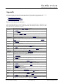
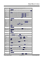
Device driver keyword reference ......................................................................................................
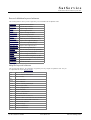
Protocol definition keyword reference ...............................................................................................
Help file keyword reference .............................................................................................................
(C) 2014, SatService GmbH
www.satnms.com
53
53
53
54
54
54
55
57
57
59
60
61
61
63
63
PR-UM-1408 Page 2/63
SatService
Gesellschaft für Kommunikationssysteme mbH
(C) 2014, SatService GmbH
www.satnms.com
PR-UM-1408 Page 3/63
SatService
Gesellschaft für Kommunikationssysteme mbH
Introduction
This is the Universal Device Driver Reference Manual to the sat-nms M&C/VLC software. It mainly
describes how to make the software interface to a certain type of equipment which is not included in the the
sat-nms device driver library for some reason.
Version 1.6 / 2014-07-11
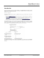
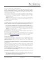
To make the sat-nms software support an additional device type, the software needs at least three
components:
1. A low level communication protocol which handles the protocol frame including device addressing or
checksum calculation.
2. A device driver which defines the parameters the operator may inspect or control at the device. The
device driver also contains the I/O routines to exchange these parameters with the device.
3. Finally, there must be a standard user interface (the so called 'device oriented user interface') for the
new device which lets an operator view or modify the device parameters.
With the sat-nms software, all three components from the physical M&C interface at the device up to the
representation of parameters on the screen are configurable and extensible by the customer. The sat-nms
software comes with library supporting a large number of devices. These files are at your's disposal to use
them as templates or as ready made module for the device driver you need to develop.
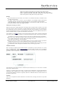
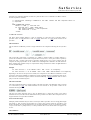
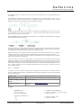
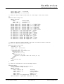
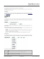
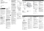
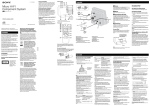
The diagram above illustrates the first steps to the integration of a new device type into the sat-nms
software. You are encouraged to use as much as possible of the existing protocol, driver and user interface
definitions.
(C) 2014, SatService GmbH
www.satnms.com
PR-UM-1408 Page 4/63
SatService
Gesellschaft für Kommunikationssysteme mbH
M&C / VLC device drivers
Device drivers in the M&C/VLC software translate abstract parameter settings which are represented by
parameter messages into commands sent to the physical device and vice versa. The basic idea is to
modularize the software in a way, that one device in a station setup can be replaced by another model,
perhaps even by a model made by another vendor, simply by selecting another device driver.
The sat-nms M&C advances this concept by introducing a 'universal device driver' which is completely user
configurable. The configurable device driver let's you write your own device drivers for device models which
are not yet supported by the software. Most of the device drivers coming with the software are built on top
of this configurable driver, so there are a lot of examples you can use as a template.
Understanding the device driver
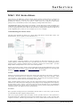
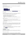
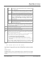
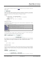
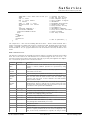
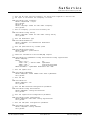
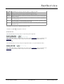
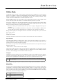
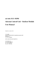
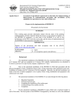
The figure below illustrates the structure of a device driver built with the 'universal device driver'. The
principal function, however, applies to 'hard coded' drivers, too.
To other software components (primarily to the user interface) the device driver interfaces by a list of
variable definitions. On the other hand, a list of procedures does the 'real work', translating the abstract
parameter values to physical command sequences. In between a function here called 'variable -- procedure
linkage' defines which procedure is run to set or read a certain parameter.
With the universal device driver, all this is setup (compiled) during the program initialization from a text file
which describes the device driver in special, but quite simple programming language. The following pages
describe how variables, procedures and the protocol encapsulation work together.
Variables
Variables are the interface between the device driver and the other components of the software, specially the
user interface. Each variable acts as an end point for a parameter message. It may receive messages -- which
causes the driver to set this parameter at the physical device -- but also may send it's parameter message in
order to tell the user interface about the actual setting of this parameter.
Inside, a variable separately stores two values: The value which recently has been commanded and the value
which has been read from the device during the previous polling cycle. By managing these values separately,
the device driver is able to check if a value has properly been set by the device. If you see messages like
'Parameter some.name set to X but reads Y' in the event log, then the parameter polling which followed a
command returned a value different from the commanded one.
Procedures
Driver procedures actually perform the communication with the device to control. They operate the device
as commanded and poll the equipment settings and state.
There are two types procedures a driver may define. A 'PUT' procedure sends one or more parameters to
the physical device after coding them into the format the physical device expects. A 'GET' procedure sends
a request to the device, reads the reply and decodes one or more variable values from the data received. A
(C) 2014, SatService GmbH
www.satnms.com
PR-UM-1408 Page 5/63
SatService
Gesellschaft für Kommunikationssysteme mbH
procure never can be both, 'PUT' and 'GET' at the same time.
The device driver executes the defined procedures in an endless loop, called the polling cycle. But a
procedure is not necessarily called in every cycle. If there is nothing to do for a particular procedure, it is
skipped. To determine which procedure must be executed in a cycle, procedures are bound to variables. A
procedure may be bound to one or more variables, however, there may me at most one 'PUT' and one
'GET' procedure referencing a variable.
A 'PUT' procedure is executed, if at least one of the variables it is bound to has received a new setting, e.g.
from the user interface. For a 'GET' procedure the following conditions cause the procedure to be executed:
1. The device driver has established communication to the device after power-on or after a
communication interruption.
2. The (individually defined) polling interval for at least one of the variables bound to this procedure has
elapsed.
3. At least one of the variables bound to the procedure has been commanded to the device. The
parameter must be read back for verification.
Protocol encapsulation
T he sat-nms device driver concept encapsulates the protocol frame used for the communication with a
device in a separate layer. This protocol layer describes which kind protocol frame has to be wrapped
around the commands sent to a device. There are a number of important advantages with this concept:
The protocol frame is automatically added to each command or request sent to the device. The other
way round, the driver automatically strips of this 'envelope' from the data received from the device.
A certain type of protocol frame needs to be programmed only once and may be used for several
device drivers, if for example different devices from the same vendor use one and the same protocol
definition.
Some devices may be operated either by one or the other communication protocol. The protocol
encapsulation allows easily to switch between the variants.
With the sat-nms software, new protocol definitions may be added to the software, simply by editing a text
file for the new type of protocol frame which is needed.
If you are going to write a new device driver, you first should investigate if there is an existing protocol
definition in the sat-nms library which can be used to serve the new device. If no protocol definition
matches, the chapter 'Device communication protocols' describes to write a new protocol definition.
Writing a device driver
As mentioned above, device drivers are coded as simple text files. When the M&C program starts, it
'compiles' the device drivers needed for it's equipment setup to memory. Writing a device driver means
editing such a text file and storing it at a place in the M&C/VLC computer where the M&C program
searches for device drivers.
The sat-nms device driver language has been designed to be very easy to understand. If you have a look at
the device driver files coming with the sat-nms software, you probably will understand most of this language
after an hour or two.
A M&C or VLC system keeps all device drivers in a subdirectory called drivers. On a M&C system this
is the directory /home/mnc/drivers, on a VLC the directory is called /home/vlc/drivers. The
name of the device driver files consist of the driver name (usually something like 'ManufacturerModelNumber') followed by the extension .device.
If you are writing the device driver on a Linux based M&C or NMS computer, you may want to use the vi
or gvim text editor for this. vi has been configured to colorize device driver files on these machines. Beside
this, vi is a very powerful editor for programming tasks.
You also may copy device driver files to a MS-Windows based computer to edit them there. If you do this,
you should consider the following:
Device driver files are Unix based text files. Lines are terminated with a line-feed character only. Your
favorite MS-Windows text editor may have problems to show these files.
Unix / Linux is case sensitive with file names. Be sure that you don't mess up the case of characters in
file name when you copy files between Unix and MS-Windows.
(C) 2014, SatService GmbH
www.satnms.com
PR-UM-1408 Page 6/63
SatService
Gesellschaft für Kommunikationssysteme mbH
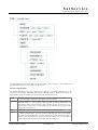
Starting from scratch
The following pages describe the 'hard way' to create a device driver from scratch. It is a good exercise to
do this once for a simple driver. In practice however, in most cases you will use an existing driver as a
template and modify this for your needs.
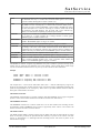
The basic steps to build a device driver from scratch are:
1.
2.
3.
4.
5.
Naming the device driver
Selecting the communication protocol
Including the standard definitions file
Defining the driver variables
Adding the data exchange procedures
If you are reading this manual online, you may open the 'NDSatCom-KuBand-Upconverter' driver example
in a separate window to watch this in parallel while you are reading the following pages.
General file format
The sat-nms device driver language has been designed to be very easy to understand. The syntax resembles
the BASIC programming language in some aspects, however, the language is highly specialized for it's
purpose. Here some basic definitions which help you to read or write device driver files:
The device driver language is case sensitive for all identifiers and keywords.
Whitespace (space characters, tabs, line breaks) separates words.
Line breaks have no special termination function.
All keywords (except the RPN commands) are in upper case letters.
Comments in C/C++ style are recognized (both, '/* ... */' and '// ... ' comments).
Identifiers (names for variables and tables) may consist of letters, digits and dots. They must start with
a letter.
Beside the rules listed above, the device drivers provided by SatService GmbH follow some sort of
coding/formatting convention:
Each file starts with a comment block containing a short description and a change history.
Identifiers always start with a lowercase letter. If a name consists of more than one word, the first
letter of each following word is in upper case. Dots are used to group parameter functionally. Example:
mod.symbolRate.
Statements are indented four columns for each level.
Naming a device driver
To create a new device driver, the first step is to give the driver a name. The device drivers supplied by
SatService GmbH all follow a 2 part naming scheme: 'VendorName-ModelDescription'. A 'Radyne
DM240' modulator e.g. appears as Radyne-DM240 in the device driver list. This makes it easy for the
person who configures the equipment setup of a M&C/VLC system to select the appropriate device drivers.
The name of the device driver appears at several places:
It is used as part of the device driver file name.
Exactly the same name should be defined as a initialized variable called 'info.type'. The online help
function and the device preset directory selection of the user interface depend on this definition.
Chapter 'Info variables' gives more information about this.
The COMMENT statement also contains the device driver name.
The COMMENT statement
The text following the COMMENT statement is free field and principally may contain any information. The
device drivers coming with the sat-nms software all follow a convention which defines the comment string
as
Driver-name X.YY YYMMDD
where X is the major version number of the driver, YY the minor version number and YYMMDD the
release date of this driver version. It is recommended that customer defined device driver follow this
(C) 2014, SatService GmbH
www.satnms.com
PR-UM-1408 Page 7/63
SatService
Gesellschaft für Kommunikationssysteme mbH
scheme, too.
The comment statement in fact creates a hidden info-variable definition. This variable with the name
'info.driver' is initialized with the comment text. At the Info-page of the device oriented user interface you
can view the comment text or the driver name /version / date respectively.
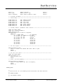
Example
COMMENT
"NDSatCom-KuBand-Upconverter 1.03 010809"
This example, taken from NDSatCom-KuBand-Upconverter device driver, identifies this driver as version
1.03, released at August, 9th, 2001.
Selecting a communication protocol
With the sat-nms software, the device communication protocol handles the low level communication
between M&C/VLC and device. There are trivial protocols which simply put a newline character at the end
of each message and more sophisticated ones dealing with start/end characters, checksums, device addresses
and more.
T he sat-nms software comes with a bunch of predefined protocol definitions. If none of these protocol
definitions matches, the chapter 'Device communication protocols' describes to write your own protocol
definition.
The communication protocol used for a certain device (for a certain serial interface, more exactly spoken) is
defined with the equipment setup which you can configure a the graphical user interface. The device driver
defines a preferred communication protocol. This means, in the device driver you state the communication
protocol this driver is designed for. At the equipment setup screen of the software you still are able to
choose a different protocol for a device of this type, however, you will be warned by the software. The
preferred communication protocol for a device driver is defined with the PROTOCOL statement:
The protocol definition this statement refers to must exist in the protocols subdirectory of the software.
Example
PROTOCOL
Miteq-MOD95
This example, taken from NDSatCom-KuBand-Upconverter device driver, defined the Miteq-MOD95
protocol as the preferred one for the driver.
File includes
ATTENTION: File including does not work when a device driver file gets interpreted by the client
software, e.g. when a device preset shall be formatted along the device driver's parameter definitions.
Variables defined in included files get not properly formatted in the device preset window. For this reason it
is recommended to use INCLUDE only for the standard includes as described in the example below!
Device driver definition files may include other files. Frequently needed definitions may be encapsulated in
included files which makes it easy to change these definitions at a central point. The syntax of the
INCLUDE statement is:
The file name given in the INCLUDE statement is relative to the M&C software's home directory. With the
sat-nms Software, there are two standard include files. Almost any driver provided by SatService GmbH
includes one of these files. The files are named 'Standard.nc' and 'StandardBin.nc' respectively. They define
the so called low level interface to the device and the fault flags which indicate a communication failure for
the device.
Example
(C) 2014, SatService GmbH
www.satnms.com
PR-UM-1408 Page 8/63
SatService
Gesellschaft für Kommunikationssysteme mbH
INCLUDE
"drivers/Standard.dotinc"
This includes the standard sat-nms include file for driver which use a text based communication protocol.
The file is located in the 'drivers' subdirectory which is one level below the M&C software's home directory.
Defining variables
Variables are the interface between the device driver and the other components of the software, specially the
user interface. Each variable acts as an end point for a parameter message. It may receive messages -- which
causes the driver to set this parameter at the physical device -- but also may send it's parameter message in
order to tell the user interface about the actual setting of this parameter.
Before you start writing the device driver, you should plan a list of variables which build the software
interface to the device. Designing this interface should be done careful, you can save a lot of effort if you
a r e able to re-use variable definitions from other devices. This not only saves the time to write the
definitions, it also enables you to use the parameter screens available for this device in the sat-nms library.
If you intend to write are driver for a device which implements similar functions as an existing driver, it is
recommended to copy the variable list from this device.
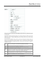
The VAR statement
Device driver variables are defined using the VAR statement. With the VAR statement you define the name,
the data type, the valid range and some other properties of the variable. This is the general syntax for a VAR
statement:
(C) 2014, SatService GmbH
www.satnms.com
PR-UM-1408 Page 9/63
SatService
Gesellschaft für Kommunikationssysteme mbH
A variable definition consists of the VAR keyword, the variable's name, a data type / range definition and
optional modifiers which control the behavior of this variable.
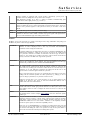
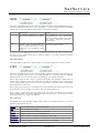
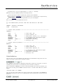
Data type / range definition
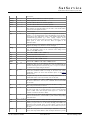
The sat-nms device driver knows about 7 data types. The data type of a variable is defined by one of the
data type keywords BOOL, INTEGER, HEX, FLOAT, CHOICE, TEXT or OBJECT, followed by the
range definition for the selected data type. Here the data types listed in tabular form:
BOOL
The BOOL data type can have the values "true" and "false". the BOOL type mainly is used
for flags which shall be displayed as signal lamps at the user interface.
INTEGER The INTEGER data type carries numeric integer values (64 bit length). When you define an
INTEGER variable, you must provide the valid range (min / max) of the variable and a unit
string which is shown at the user interface right of the data. If both, min and max are zero
the user interface software does no range check at all. The unit string may be empty, but the
double quotes are required ("").
HEX
The HEX data type also is a 64 bit integer, but formatted in hexadecimal notation.
FLOAT
The FLOAT data type carries double precision (64 bit length) floating point values. When
you define a FLOAT variable, you must provide the valid range (min / max) of the variable,
the number of fraction digits and a unit string which is shown at the user interface right of
the data. If both, min and max are zero the user interface software does no range check at
all. The unit string may be empty, but the double quotes are required ("").
(C) 2014, SatService GmbH
www.satnms.com
PR-UM-1408 Page 10/63
SatService
Gesellschaft für Kommunikationssysteme mbH
FLOAT variables are displayed with a fixed precision. Alternatively you may force a
scientific notation by adding 100 to the precision value. Example:
VAR myFloat FLOAT 0 0 103 "" defines a scientific formatted floating point
variable shown with 3 digits precision (e.g. '0.123E-2')
CHOICE
The CHOICE data type defines a parameter which may contain one of a fixed set of string
values. You define this set as a comma separated list, enclosed in double quotes. At the user
interface such a parameter appears as a drop down box where you can select a value from
this list.
TEXT
The TEXT data type carries an arbitrary character string.
OBJECT
The OBJECT data type is used with complex variables which cannot be shown by the
standard user interface routines. OBJECT variables only appear together with logical devices,
you never will need this data type when writing a device driver.
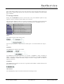
Modifiers
Modifiers control some properties of a variable concerning it's state, usage, initialization and polling cycle.
Modifiers may before or after the type definition.
DISABLED
Variables may be 'enabled' or 'disabled'. Disabled variables appear grey at the user
interface, no value is displayed and no value may be entered. The RANGESET
command is used to change the enable state.
By default variables start in enabled state unless they are marked as DISABLED in the
VAR statement. Disabling a variable at this point may be useful if the variable stands
for a parameter which is not available at all models of the device type the driver is
written for. The variable can be enables by the driver when it detects that the device
actually connected to the M&C/VLC supports this parameter.
READONLY
Marking a variable READONLY prohibits the operator from changing it's value. This is
used for state variables like meter readings. The range information for the data type
used must be provided even if the variable is marked READONLY.
CYCLE
The CYCLE modifier controls the frequency (expressed as time interval in seconds),
this variable shall be polled from the device. By default, variables are read from the
device with every working cycle of the driver. This is about one a second if only a few
parameters are to read. With many parameters the polling rate will be lower as the
response time for each interrogation extends the cycle time.
Hence, most device drivers poll only a few parameters like alarm flags or some meter
readings with the maximum possible rate. Other parameters, e.g. settings you do not
expect to change by themselves, are polled at a much lower rate.
Setting the CYCLE time to zero causes the driver to do no regular polling for this
variable at all. However, after power up and after communication failures, such a
variable still is read once from the device
INIT
Using the INIT modifier, a variable may be initialized to a certain value. This value
remains valid until the variable gets polled the first time. The INIT option often is used
with variables which are used to configure the driver and never are read from the
device itself.
SETUP
The SETUP modifier marks a variable to be listed in the maintenance/setup window of
the standard device screens. Chapter 'Setup variables' tells more about this special
variable type.
NOPRESET
Using the NOPRESET modifier, a variable can be explicitely excluded from the set of
parameters which are written to a device preset. A device preset contains all variables
which define a PUT prozedure and are no SETUP parameters and don't have the
NOPRESET modifier set. The 'reset' variable - if defined - is also implicitely excluded
from device presets preset, for backward compatibility reasons.
Please note, if you add NOPRESET to a variable in an existing device driver, this will
not remove the value for this variable from existing device presets, it only will prevent
the software from adding the value to new presets. You may use the preset editor to
remove the unwanted value manually from existing device presets.
(C) 2014, SatService GmbH
www.satnms.com
PR-UM-1408 Page 11/63
SatService
Gesellschaft für Kommunikationssysteme mbH
NOCOMPARE Without the NOCOMPARE modifier the device driver will compare a value it
commanded to the device against the value it read back after this. If the two values
differ, an informational message showing the commanded and the read value is added
to the log. NOCOMPARE suppresses this check. This is useful with parameters which
are known for reading back in a wrong way, frequent messages in the log can be
avoided this way.
SAVE
The SAVE modifier tells the driver to save this variable on disk and to restore it's value
when the program starts. Usually all device settings are stored in the device itself, the
M&C/VLC system does not change anything at a device when it starts.
In some cases, e.g. with SETUP variables or if the driver implements a receive level
threshold, it is useful to store variable values in the M&C system rather in the device.
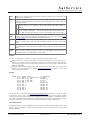
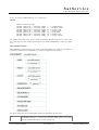
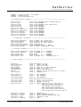
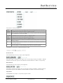
Example
VAR
VAR
VAR
VAR
VAR
VAR
VAR
audio.1.dotprogram
audio.1.dotrouting
audio.1.dotoutput
audio.1.dotlevel
audio.1.dotlanguage
audio.1.dottest
audio.1.dotinfo
CYCLE
CYCLE
CYCLE
CYCLE
CYCLE
CYCLE
CYCLE
0
0
0
0
0
0
4
INTEGER 0 0 ""
CHOICE "NRM,MON,LFT,RGT"
CHOICE "ANALOG,AES/EBU,SPDIF,AC3"
INTEGER 6 18 "dB"
TEXT
CHOICE "NRM,TEST-1,TEST-2,TEST-3,TEST-4,TEST-5"
TEXT READONLY
The ALARM statement
Alarm flags are a special variant of variables. They always are of the type BOOL and they are
READONLY. For each ALARM variable you define a text message which appears in the 'Faults' page of the
device's user interface screen and as a message in the event log if the value of the flag changes. The device
driver summarizes all alarm flags with each cycle and generates a summary fault information for the device.
Alarm flags are defined with the ALARM statement:
An alarm flag definition consists of the ALARM keyword, the flag's name and an optional CYCLE
definition which work analogous to the CYCLE modifier in a VAR statement.
The name of an alarm flag must be of the form faults.XX where XX is a two digit number in the range from
01 .. 98. The faults.99 is reserved for a communication fault.
The alarm flag definition may include an INIT clause which initializes the fault priority value of the flag.
INIT must be followed by one of "OFF", "INFO", "WARNING", "FAULT" or "ALARM".
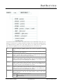
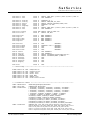
Example
ALARM faults.01
(C) 2014, SatService GmbH
TEXT "Remote access" INIT "WARNING"
www.satnms.com
PR-UM-1408 Page 12/63
SatService
Gesellschaft für Kommunikationssysteme mbH
ALARM
ALARM
ALARM
ALARM
ALARM
ALARM
faults.02
faults.03
faults.04
faults.05
faults.06
faults.07
TEXT
TEXT
TEXT
TEXT
TEXT
TEXT
"Synthesizer"
"LO-A lock"
"LO-B lock"
"Power supply"
"IF-LO level"
"RF-LO level"
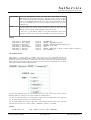
Info variables
Each device driver defines a number of so called info variables which tell the operator, but also the client
software about the device driver. All info variables
are named starting with info.
are defined READONLY
The user interface contains a special screen which display the contents of all info variables the driver
defines.
Info variables are used to display information like device types, serial numbers etc. Beside this, there are
three info variables each device driver must define in any case. They are:
info.type
This variable tells the user interface name of the device driver. It is used to select the
subdirectory for device presets and to find the help screen for this device driver. info.type
must be initialized to the name of the device driver which in fact is the file name with the
trailing '.device' cut off.
info
This variable is set by the device driver to the name of the serial port which is used to access
the device. This is for convenience, offering the operator this information without opening
the device setup.
ort
info.frame The standard user interface uses the value assigned to this variable to select the 'device
oriented' screen set for this device. info.frame must be initialized to name of the device
frame definition file to be used with this device.
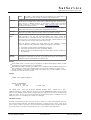
Example
VAR
VAR
VAR
VAR
VAR
info.type
info.port
info.frame
info.model
info.serial
CYCLE
CYCLE
CYCLE
CYCLE
CYCLE
0
0
0
0
0
TEXT
TEXT
TEXT
TEXT
TEXT
READONLY INIT "Tandberg-Alteia"
READONLY
READONLY INIT "IRD-Alteia"
READONLY
READONLY
The example above - taken from the Tandberg-Alteia device driver - identifies the driver as 'Tandberg-Alteia'
and tells the user interface to use the device oriented frame set called 'IRD-Alteia' for this device. The info
variables info.model and info.serial are set by the driver later, when it read the model description and serial
number from the device.
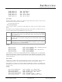
Setup variables
Another group of variables which are treated specially by the driver are setup variables. They are used to
configure the device driver or to set parameters which shall not appear at the standard user interface.
Setup parameters are shown in an own screen which is accessible only to operators of a privilege level of
150 and above. Setup variables must be marked with the SETUP modifier, the name of setup variables must
start with '.config'.
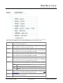
Example
VAR
VAR
VAR
VAR
VAR
VAR
config.lbandInputs
config.lnbPower
config.loFreq
config.berThreshold
config.sigThreshold
config.errFrame
(C) 2014, SatService GmbH
CYCLE
CYCLE
CYCLE
CYCLE
CYCLE
CYCLE
0
0
0
0
0
0
CHOICE "4,2" SETUP SAVE
CHOICE "OFF,ON.,BST" SETUP
FLOAT 0 0 1 "MHz" SETUP
TEXT SETUP
INTEGER 0 255 "" SETUP
CHOICE "FREEZE,BLACK" SETUP
www.satnms.com
PR-UM-1408 Page 13/63
SatService
Gesellschaft für Kommunikationssysteme mbH
The example above - taken from the Tandberg-Alteia device driver - defines a setup variable
'config.lbandInputs' which configures the driver for 2- or 4-input models of the IRD. This variable also is
marked with the SAVE modifier to make the setting permanent. The following variables in the example are
configuration settings which are placed in the setup area to keep them out from the common user interface.
Variables for internal use
Variables may be used to store intermediate values in the driver. For instance, a bit field status value may be
read into a variable and then interpreted using the BITSET command.
Variables for internal use must be declared READONLY to work properly. Even though not required, it is
recommended to give these variables a descriptive name which tells about the internal usage of this variable.
The following example is taken from the SSE KStar device driver:
VAR internal.state HEX 0 0 " " READONLY
CYCLE 2
...
PROC GET WATCH internal.state
PRINT "AL"
INPUT "=" internal.state
BITSET faults.01 = internal.state 9
BITSET faults.02 = internal.state 15
BITSET faults.03 = internal.state 11
...
Using conversion tables
CHOICE parameter often are implemented by the device's remote control protocol as numeric constants (0
for BPSK, 1 for QPSK) or they are abbreviated in a way which is hard to remember. The user interface of
the software shall in contrast display self-explaining names for such settings.
The driver language lets you define translation tables which do such conversions while the driver performs a
PRINT, INPUT, READ or WRITE statement. As the driver knows, in which direction a table translation
must be done, you can use the same table to translate values when they are written to and when they are
read from the device.
The TABLE statement described in following chapter is used to define translation tables.
The TABLE statement
The driver language lets you define translation tables which do such conversions while the driver performs a
PRINT, INPUT, READ or WRITE statement. Tables are defined with the TABLE statement:
The TABLE keyword is followed by a name for this table and the table definition in double quotes. The
table definition contains assignments 'A=B', separated by commas. Strings containing commas or equal
characters cannot be translated through a table.
TABLE tModulation
"BPSK=BPS,QPSK=QPS,8PSK=8PS"
In the table definition, the 'A' value is the string visible at the user interface of the software, the 'B' value is
used when communication with the device. The driver translates in a PRINT or WRITE statement BPSK > BPS, QPSK -> QPS or 8PSK -> 8PS if the table tModulation shown in the example above is referenced.
With an INPUT or READ statement, the table automatically translates the values the other way round.
For some applications a table definition may become quite large. The driver syntax permits to split up the
table definition in multiple string/lines. Each string/line must be enclosed in double quotes and must contain
at least one translation pair. Commas at the end of a line are omitted. Below an example for such a multi
line table definition is shown.
TABLE tVideoTest
(C) 2014, SatService GmbH
"NRM=00,625.1=01,625.2=02,625.3=03,625.4=04,625.5=05"
"625.6=06,625.7=07,625.8=08,625.9=09,625.10=10,625.11=11"
www.satnms.com
PR-UM-1408 Page 14/63
SatService
Gesellschaft für Kommunikationssysteme mbH
"625.12=12,625.13=13,625.14=14,625.15=15,625.16=16"
"525.1=17,525.2=18,525.3=19,525.4=20,525.5=21,525.6=22"
"525.7=23,525.8=24,525.9=25,525.10=26,525.11=27,525.12=28"
"525.13=29,525.14=30,525.15=31,525.16=32"
Remarks
If a table translation is invoked with a value which is not contained in the table, the translation returns
the first value in the table.
To define a table it may be useful to copy the definition of the CHOICE variable which shall be
translated at the place of the table statement. this copy then can be extended to the table definition.
Don't add whitespace characters in the table definition to make this better readable. The driver would
treat these characters as part of the strings to translate!
Adding data exchange procedures
While the device driver variables discussed in the chapters above specify the driver's interface to the other
parts of the software, does the device driver procedure implement the interface to the device itself. Based on
the communication protocol selected in the equipment setup (the protocol handles the low level coding of
the data exchanged with the device), procedures handle the chats done between the M&C and the device to
perform parameter settings or to gain some information from the device.
The description of the PROC statement in the following chapter together with the examples supplied with
this manual explain the usage of procedures. Generally the following rules apply to device driver procedures:
Procedures are executed by the driver in the same order as they are defined in the driver specification.
The driver knows GET-type procedures which read some information from the device into one or
more variables and PUT-type procedures which send settings to the device.
A procedure may handle one or more parameters.
The driver skips any procedures where actually nothing is to do. For example a PUT-type procedure is
skipped unless at least one of the values handled by it has been changed by the operator.
A variable which has it's data source in the device must be handled at exactly one GET-type procedure.
A variable being a device setting must be handled at exactly one PUT-type procedure.
The PROC statement
Driver procedures are defined with the PROC statement. The PROC keyword is followed by one of PUT,
GET or SUBROUTINE. Chapter 'Using subroutines' tells more about the latter type of procedures.
Procedures do not have an explicit 'end' keyword, a procedure automatically ends where another definition
(procedure, variable or table) starts.
PUT and GET type procedures must have a WATCH keyword followed by one or more names of variables
this procedure shall be bound to.
Generally, any variable which is referenced in a procedure must be defined before using the VAR statement.
Although the driver language allows to define variables between procedures (a VAR statement closes an
open procedure definition), the drivers supplied by SatService GmbH first define all variables and then all
procedures for this reason.
Examples
There are two complete device drivers listed at the end of this section, showing several flavors of procedure
definitions:
(C) 2014, SatService GmbH
www.satnms.com
PR-UM-1408 Page 15/63
SatService
Gesellschaft für Kommunikationssysteme mbH
NDSatCom-KuBand-Upconverter device driver
Tandberg-Alteia device driver
Basic I/O functions
The primary function of a driver procedure is to acquire some information from the device ('GET'
procedure) or to set one or more parameters from the data commanded somewhere else in the software
('PUT' procedure). The sat-nms device driver definition language provides four highly flexible statements for
this purpose. They are:
PRINT
Composes/formats s (readable) string from multiple elements which may be text fragments,
numbers (formatted in various ways), tokens from a CHOICE variable and more. The
composed string is packed in a protocol frame and sent to the device. PRINT is used with
devices which implement a text based protocol.
INPUT
The INPUT statement complements the PRINT statement. It reads a message from the
device, strips off the protocol frame parses the received data according to the rules specified
with the INPUT statement.
WRITE
The WRITE statement is the equivalent to PRINT for devices providing a binary
communication protocol. WRITE sets up a binary data structure from constant and variable
values, packs this structure in a protocol frame and sends it to the device.
READ
Reading data from a device providing a binary communication protocol is done with the
READ statement. As the counterpart of the WRITE statement it reads a message from the
device, strips off the protocol frame and provides means to interpret the received data as a
binary structure variables.
The PRINT statement
The PRINT statement is used to send commands to a device which uses a text based protocol. It composes
a command string from the elements following the the PRINT keyword, packs this string in the protocol
frame defined by the communication protocol and sends this message to the device. The syntax of the
PRINT statement is:
The table below describes the elements which may follow the PRINT keyword.
" text "
Plain text, enclosed in double quotes, is added to the output buffer as it is.
asciicode
A decimal number is interpreted as the ASCII code of a single character to output. You may
use this to send special characters like carriage-return or line-feed to the device.
XLT
table
The XLT keyword, followed by the name of an already defined table, tells the driver to
translate the next variable value which shall be printed through this translation table. Chapter
'Using conversion tables ' gives more information about tables in general.
FMT
"..."
The FMT keyword, followed by a format description in double quotes, tells the device driver
to format the next variable following the format description given. FMT is used to format
numeric variables into the representation the device expects in it's remote control command. A
format description consists of the following elements:
(C) 2014, SatService GmbH
www.satnms.com
PR-UM-1408 Page 16/63
SatService
Gesellschaft für Kommunikationssysteme mbH
dbxXf
The first letter of the format description defines the general number
representation: d (decimal), b (binary), x (hex, lower case), X (hex, upper
case) or f (floating point)
+
If the + option is given, the number is preceded by a +/- character even if it is
positive. Together with the '0' option below, the sign appears as an additional
character at the first column, hence the field width is increased by one on this
case.
0
If the '0' option is given, the field is padded up with zeroes instead of spaces.
1 .. 99
Here follows a one or two digit field width. The field width is the total number
of characters the formatted number occupies including the padding characters.
If there are more digits needed to show a number correctly, the field with is
enlarged automatically. Specifying a field width '1' disables the right
orientation in a fixed width completely. This specially is useful for floating
point numbers where only the number of fraction digits shall be fixed, not the
complete field width.
.
For floating point formats the dot separates the precision from the field width.
0 .. 9
The dot is followed by a one digit specification of the number of fraction
digits which shall be printed. The dot and fraction digits specification is valid
only with the floating point format.
INTEGER variables may be printed using a floating point format, and FLOAT variables may
be printed with a 'd' or 'x' format likewise. With FLOAT variables you should format in any
case as internal precision/rounding problems may cause unpredictable results when floating
point values are printed unformatted.
OFFSET The OFFSET keyword, followed by the (floating point) offset value, tells the driver to add the
o
offset value to the next variable before it is printed.
SCALE
s
The SCALE keyword, followed by the (floating point) scale factor, tells the driver to multiply
the next variable with the scale factor before it is printed
variable- A variable name tells the driver to print the value stored in this variable. Usually the
name
commanded value is used rather than the value which has been read back from the device. If,
however, there has been never a value commanded, or if this variable is a read only variable,
the value recently read from the device is used.
Before the variable is printed to the output buffer, any XLT, FMT, OFFSET or SCALE
operations which have been specified are applied. This happens in a fixed order:
1.
2.
3.
4.
If a SCALE operation has been specified, this is done first.
The SCALE operation is followed by an OFFSET addition.
The so scaled value is formatted according to a FMT specification if one is given.
Finally, the value gets translated through a translation table, if an XLT operation has
been specified.
This scheme applies to numeric (INTEGER, HEX, FLOAT) and to text type variables as well.
As soon as a SCALE, OFFSET or FMT keyword is present in front of a variable, this gets
converted to a floating point number. Strings which cannot be converted give a zero value.
Example
PRINT "TUN;FRQ=" SCALE 8.0 FMT "d06" frequency
The example above sends a command of the format 'TUN;FRQ=######' to the device. The FLOAT
variable 'frequency' is multiplied by 8.0 and the output as an integer number, 6 digits wide with leading
zeroes.
The INPUT statement
The INPUT statement is used to read and interpret the reply of a device which uses a text based
communication protocol. It reads a protocol frame from the device and parses the received message
according to the rules defined by the description following the INPUT keyword. The syntax of the INPUT
statement is:
(C) 2014, SatService GmbH
www.satnms.com
PR-UM-1408 Page 17/63
SatService
Gesellschaft für Kommunikationssysteme mbH
While parsing the device's reply, the driver deals with three information buffers. To understand the way how
the parsing operations work which may follow the INPUT keyword, it is necessary to learn how the driver
uses these buffers.
The first buffer contains the original reply string as it is received from the device (with the protocol frame
stripped off). The driver initially copies this string into a second buffer called pad. Search operations (text in
double quotes) and the "+" operation modify the pad. The AT operation is the only way to restore the pad
from the original data.
Every time, the pad is modified, the driver copies it's contents into the third buffer called value. Value is the
string which will be assigned to a variable if it appears in the list of arguments to the INPUT statement.
Operations in the INPUT statement like CUT, TRM, or XLT work on the value buffer but leave the pad
unchanged. This is important to understand if you have to parse the value of more than one variable in a
single INPUT statement.
"
pattern
"
Searches the text/pattern in the current pad buffer. If the pattern is found, all text including the
first occurrence of the pattern is removed from the beginning of the pad buffer.
+n
Removed n character from the beginning of the pad buffer.
AT n
Restores the pad buffer with a substring of the original data, starting at column n.
CUT n
Cuts the value buffer to a length of n characters.
TRM
"c"
Removes the first occurrence of the termination character and all following text from the
value buffer. The termination character may be specified as a decimal number (e.g. 10 is the
ASCII code for line feed) or as a single character enclosed in double quotes.
BIT n
Interprets the value buffer as a decimal number and isolates the bit number n (n = 0 means
the least significant bit). The value buffer is replaced by '0' or '1' depending on the bit value.
CBER
Interprets the value buffer as a bit error rate value as it is returned by Comstream modems. A
string 'mn' is converted into the more common notation 'mE-n'.
(C) 2014, SatService GmbH
www.satnms.com
PR-UM-1408 Page 18/63
SatService
Gesellschaft für Kommunikationssysteme mbH
SKIP
Removes any whitespace (space characters, line feeds, carriage returns or tabs) from the
beginning of the value buffer.
HEX
".."
Interprets the contents of the value buffer as a hex number and replaces it by it's decimal
equivalent. The format definition string which must follow the HEX keyword may contain the
following characters:
L The hex number is in 'little endian' notation. This means the least significant byte is
written at first. If no 'L' character is in the format string, 'big endian' notation is
assumed.
S
XLT
table
The hex number is signed. The number of digits is used to calculate the sign extension:
'80' for example is calculated as '-1' as the two digit number is assumed to be a byte
value. '0080' in contrast is computed to '128' as a 16 bit number of this value is positive.
The XLT keyword, followed by the name of an already defined table, tells the driver to
translate the value buffer through this translation table from right to left. Chapter 'Using
conversion tables' gives more information about tables in general.
OFFSET The OFFSET keyword, followed by the (floating point) offset value, interprets the value
o
buffer as a floating point number and replaces the buffer with the sum of the value and the
offset.
SCALE
s
The SCALE keyword, followed by the (floating point) scale factor, interprets the value buffer
as a floating point number and replaces the buffer with the product of the value and the scale
factor.
variable- A variable name tells the driver to assign the contents of the value buffer to this variable. The
name
driver performs format conversions and range checks according to the type and limit
specifications made in the VAR definition of this variable.
Remarks
If a value is not assigned to a variable as you expect, you should check the following issues:
Numeric values are converted from string to numeric representation in a very lenient way. For
instance, any leading non-numeric characters are ignored. If a numeric variable is not assigned as
expected, in most cases there is a range violation. The driver does not accept values outside the range
defined for this variable.
CHOICE variables and tables (referenced with the XLT operation) expect an input value which exactly
matches one of the valid choices. See chapter 'Using conversion tables ' to read how you can make
tables somewhat fault tolerant.
Example
INPUT AT
AT
AT
AT
AT
AT
AT
AT
AT
AT
AT
2
11
15
17
19
21
22
23
24
25
26
SCALE
SCALE
CUT 1
CUT 1
CUT 1
CUT 1
CUT 1
CUT 1
CUT 1
CUT 1
CUT 1
0.001
tx.frequency
-0.1 OFFSET 30.0 tx.gain
XLT T03
faults.01
XLT T02
info.if
XLT T01
tx.on
faults.02
faults.03
faults.04
faults.05
faults.06
faults.07
The example above -- taken from the NDSatCom-KuBand-Upconverter device driver -- parses all settings
an faults flags from a single status string the upconverter returns. Note that the numeric variables
'tx.frequency' and 'tx.gain' are isolated from the string without specifying a length or a termination character.
The number recognition routine automatically stops where it finds a non-numeric character after the number
to read. The other values however all are cut to one character length before they are interpreted.
The WRITE statement
The WRITE statement is used to send data to the device which uses a binary communication protocol. Such
a device expects a command as a binary data structure rather than as a readable text. The syntax of the
WRITE command is:
(C) 2014, SatService GmbH
www.satnms.com
PR-UM-1408 Page 19/63
SatService
Gesellschaft für Kommunikationssysteme mbH
The WRITE statement creates a buffer of the specified number of bytes which initially is filled with zeroes.
Variables or constant values are copied into this buffer according to the size and position specifications given.
The WRITE statement by default works in 'little endian' mode. 16, 32 or 64 bit values are copied into the
buffer with the least significant byte first. Specifying BIGENDIAN mode reverses this byte order.
size
The size (number of bytes) of the message buffer to create must be specified as the first
argument following the WRITE keyword. The size value is expected as a decimal
number.
BIGENDIAN The BIGENDIAN keyword turns the byte order from 'little endian' (LSB first) which is
the default to 'big endian' (MSB first).
INT8 p
The INT8 keyword, followed by a decimal position value, tells the driver that the next
constant or variable shall be copied to the buffer as a single byte value at the given
position (position zero denotes the first byte in the buffer).
INT16 p
The INT16 keyword, followed by a decimal position value, tells the driver that the next
constant or variable shall be copied to the buffer as a two-byte value starting at the given
position (position zero denotes the first byte in the buffer). The least significant byte of
the number is placed first unless BIGENDIAN was specified.
INT32 p
The INT32 keyword, followed by a decimal position value, tells the driver that the next
constant or variable shall be copied to the buffer as a four-byte value starting at the given
position (position zero denotes the first byte in the buffer). The least significant byte of
the number is placed first unless BIGENDIAN was specified.
INT64 p
The INT32 keyword, followed by a decimal position value, tells the driver that the next
constant or variable shall be copied to the buffer as a eight-byte value starting at the given
position (position zero denotes the first byte in the buffer). The least significant byte of
the number is placed first unless BIGENDIAN was specified.
BITS p:b:w
The BITS keyword tells the driver to place the next value as a 1 to 7 bit wide bit field
within a certain byte. In this case the position parameter consists of three values,
separated by colons:
position addresses the byte within the buffer. te
bitpos
(C) 2014, SatService GmbH
defines a number of bit positions the value shall be shifted left before it is
pasted into the byte.
www.satnms.com
PR-UM-1408 Page 20/63
SatService
Gesellschaft für Kommunikationssysteme mbH
width
the number of bits (starting with the least significant one) which shall be
copied from the next constant or variable into the destination byte.
XLT table
The XLT keyword, followed by the name of an already defined table, tells the driver to
translate the next variable value which shall be printed through this translation table.
When output by a WRITE statement, any non-numeric variable must be translated
through a table into a numeric value. Chapter 'Using conversion tables ' gives more
information about tables in general.
OFFSET o
The OFFSET keyword, followed by the (floating point) offset value, tells the driver to
add the offset value to the next variable before it is pasted into the buffer.
SCALE s
The SCALE keyword, followed by the (floating point) scale factor, tells the driver to
multiply the next variable with the scale factor before it is pasted into the buffer
variablename
A variable name tells the driver to paste the value stored in this variable into the output
buffer according to the size and position specification given before. Usually the
commanded value is used rather than the value which has been read back from the
device. If, however, there has been never a value commanded, or if this variable is a read
only variable, the value recently read from the device is used.
Before the variable is printed to the output buffer, any XLT, OFFSET or SCALE
operations which have been specified are applied. This happens in a fixed order:
1. If a SCALE operation has been specified, this is done first.
2. The SCALE operation is followed by an OFFSET addition.
3. Finally, the value gets translated through a translation table, if an XLT operation has
been specified.
numericconstant
Numeric (decimal) constants can be used like variable names. The constant value is
pasted into the output buffer in this case. If a quoted string is given, this is treated as a
hexadecimal constant and translated into a numeric value.
Remarks
Each variable name or constant must be preceded by an INT8, INT16, INT32, INT64 or BITS
specification to be pasted properly into the output buffer.
Only INTEGER, HEX or FLOAT type variables can be used directly with the WRITE statement. For
other variable types an XLT table translation must be used to turn the variable into a numeric value.
FLOAT variables are converted to 64-bit integer values before they are used. OFFSET or SCALE
operations are done before this conversion.
Example
TABLE T02 "QPSK=0,BPSK=1"
...
WRITE 3 BIGENDIAN
INT16 0 9734
INT8 2 XLT T02
tx.mod.type
The example above -- taken from the Radyne DVB3030 modulator driver -- explains how to write a
CHOICE parameter to a device. Table T02 is used to convert the QPSK/BPSK selection into the numeric
values 0/1. The WRITE statement sends a message (three bytes long plus protocol frame overhead) in 'big
endian' byte order. The first two bytes are filled with the decimal constant 9734 (a command code). The
third byte is set to 0 or 1 according to the contents of 'tx.mod.type'.
The READ statement
Receiving and interpreting of data returned from devices which use a binary communication protocol is
done with the READ statement. The READ statement gets a message from the device, strips off the
protocol frame and places the result in an internal buffer. Subcommands/operations following the READ
keyword are used to copy values from the buffer into one or more variables of the device driver.
(C) 2014, SatService GmbH
www.satnms.com
PR-UM-1408 Page 21/63
SatService
Gesellschaft für Kommunikationssysteme mbH
The READ statement by default works in 'little endian' mode. 16, 32 or 64 bit values are read from the
buffer with the least significant byte first. Specifying BIGENDIAN mode reverses this byte order.
BIGENDIAN The BIGENDIAN keyword turns the byte order from 'little endian' (LSB first) which is
the default to 'big endian' (MSB first).
INT8 p
The INT8 keyword, followed by a decimal position value, tells the driver that the next
variable appearing in the argument list shall be filled from a single byte value at the given
position (position zero denotes the first byte in the buffer).
INT16 p
The INT16 keyword, followed by a decimal position value, tells the driver that the next
variable appearing in the argument list shall be filled from a two-byte value starting at the
given position (position zero denotes the first byte in the buffer). The least significant
byte of the number is read first unless BIGENDIAN was specified.
INT32 p
The INT32 keyword, followed by a decimal position value, tells the driver that the next
variable appearing in the argument list shall be filled from a four-byte value starting at the
given position (position zero denotes the first byte in the buffer). The least significant
byte of the number is read first unless BIGENDIAN was specified.
INT64 p
The INT64 keyword, followed by a decimal position value, tells the driver that the next
variable appearing in the argument list shall be filled from a eight-byte value starting at
the given position (position zero denotes the first byte in the buffer). The least significant
byte of the number is read first unless BIGENDIAN was specified.
BITS p:b:w
The BITS keyword tells the driver to read a 1 to 7 bit wide bit field from a certain byte
in the buffer. In this case the position parameter consists of three values, separated by
colons:
position addresses the byte within the buffer. te
bitpos
defines the bit-number (0 to 7) of the least significant bit to read.
width
the number of bits which shall be copied from the buffer into the destination
variable.
XLT table
The XLT keyword, followed by the name of an already defined table, tells the driver to
translate the value read through this translation table from right to left. Chapter 'Using
conversion tables' gives more information about tables in general.
OFFSET o
The OFFSET keyword, followed by the (floating point) offset value, tells the driver to
add the given offset to the value read.
SCALE s
The SCALE keyword, followed by the (floating point) scale factor, tells the driver to
(C) 2014, SatService GmbH
www.satnms.com
PR-UM-1408 Page 22/63
SatService
Gesellschaft für Kommunikationssysteme mbH
multiply value read with the given factor.
variablename
A variable name tells the driver to store the value read into the variable.
Example
READ BIGENDIAN
INT32 1 SCALE 0.000001
INT32 7
INT32 11 SCALE 0.000001
INT8 15 XLT T01
INT8 16 XLT T02
INT8 17 XLT T03
INT16 22 SCALE 0.1
INT8 24 XLT T04
INT8 24 XLT T04
INT8 25 XLT T05
INT8 26 XLT T06
INT8 28 XLT T14
INT8 29 XLT T06
INT8 30 XLT T06
INT8 31 XLT T07
INT8 44 XLT T08
INT32 45
INT32 49
INT8 53 XLT T09
INT8 54 XLT T10
INT8 55 XLT T11
INT8 57 XLT T12
tx.frequency
tx.mod.dataRate
refClkFreq
refClkSrc
tx.mod.type
tx.mod.fec
tx.power
tx.on
internal.tx.on
tx.mod.cwMode
tx.mod.spectrumInvert
tx.ifc.hardware
tx.ifc.clockPhase
tx.ifc.dataPhase
tx.mod.clockSource
info.maskEnable
info.alarmMask
tx.mod.symbolRate
tx.ifc.framingMode
tx.mod.rollOff
config.control
modemType
The example above -- taken from the Radyne DVB3030 modulator driver -- shows the main settings READ
statement of this driver. In one step almost all parameter settings are read.
Using subroutines
Procedures may be defined to act as subroutines (see chapter 'The PROC statement' for the syntax
description). They are not bound to variables in this case. The CALL statement is used to invoke a
subroutine from another procedure.
Subroutines are suitable to code operations which have to be done in the same way in several procedures. A
common application for this is the check of the device's reply to a command. A subroutine can read the
device's reply, check if it is OK and raise a fault flag if not. After a procedure sends a command to the
device, it calls the subroutine which does the check.
When using subroutines, you should notice the following:
Subroutines may be nested, this means a subroutine may contain a CALL statement to another
subroutine.
Subroutines must be defined before they can be referenced in another procedure.
The device driver language allows to define recursive subroutines (subroutines which call themselves).
You are strongly discouraged to program recursive subroutines as a program bug in your device driver
may cause infinite recursion which definitely will crash the whole M&C application!
The CALL statement
The CALL statement is used to invoke a subroutine from another procedure. The called routine must be
defined before it can be called.
The driver executes all statements of the called procedure and then resumes
Examples
The example below, taken from the Tandberg-Alteia device driver, shows a common application of a
(C) 2014, SatService GmbH
www.satnms.com
PR-UM-1408 Page 23/63
SatService
Gesellschaft für Kommunikationssysteme mbH
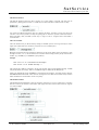
subroutine. The subroutine getAck is called every time the driver sent a command to the IRD to check if
the unit accepted the command.
// called after sending a command to the IRD. checks the ACK response which is
// expected.
//
PROC SUBROUTINE getAck
INPUT "=" TRM "_" internal.ack
IF internal.ack = "ACK" GOTO endif
SET faults.commstat = "ACK expected"
SET faults.99 = "true"
:endif
Conditional execution
The device driver language defines a couple of statements to control the flow of execution within a
procedure. There is an IF statement as well as a GOTO which refers to a label placed elsewhere in the
procedure.
The IF statement
The IF statement conditionally executes a single statement if the comparison following the IF keyword is
true.
The keyword IF is followed by a comparison of a variable to another variable or constant. With the '='
operator the command is executed if the compared values match, with '!=' if they don't match respectively.
Please note, that a constant value must be enclosed in double quotes, even if it is a numeric value. IF
compares the string representation of the variables after formatting them as defined in the VAR statement.
Hence, floating point variables always are compared after being rounded to the number of digits defined for
the user interface display.
Example
IF info.version = "2.0" PRINT "TFR " FMT "f1.3" tx.frequency
IF info.version != "2.0" PRINT "TFR " FMT "d08" SCALE 1000.0 tx.frequency
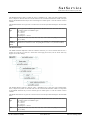
Depending on the value of the info.version variable, the example above uses different commands to set the
tx.frequency at the device. PRINT is considered as a single command, with all it's parameters in this case. If
more than one command in sequence shall be executed conditionally, a GOTO statement must be used to
jump over the this command sequence.
The GOTO statement
The GOTO statement branches to another location in the same procedure. The destination where to branch
to is referenced by a label. The GOTO statement lets the execution of the procedure continue at the
statement following the label.
The label, the GOTO statement refers to may be defined above or below the location of the GOTO
statement. However, the label must be defined in the same procedure. The device driver interpreter does not
support branches across procedure boundaries.
Some words about loops
Principally GOTO statements may be used to create loops within a procedure. You are strongly discouraged
from doing so. This is because all procedures for a device (more exactly spoken the procedures of all
devices operated at the same physical interface) are executed sequentially. If now one procedure is caught in
a loop for some time or perhaps forever, no other procedures will run. The device driver will appear to be
'frozen'.
Label definition
(C) 2014, SatService GmbH
www.satnms.com
PR-UM-1408 Page 24/63
SatService
Gesellschaft für Kommunikationssysteme mbH
Labels are defined as destination locations for the GOTO statement. The colon, followed by a label name
defines a label:
Labels only are visible within the procedure where they are defined. As a consequence, you may define
labels with the same name in different procedures. Within one procedure however, a label name may be
used only once. Between the colon and the label name no whitespace is required.
Example
IF info.version = "2.0" GOTO v2stuff
PRINT "TFR " FMT "d08" SCALE 1000.0 tx.frequency
GOTO finished
:v2stuff
PRINT "TFR " FMT "f1.3" tx.frequency
:finished
Manipulating variables
The sat-nms device driver definition language provides a number statements to manipulate driver variables
within procedures. These are:
SET
Assigns a value to a variable.
BITSET
Extracts a single bit from a variable and assigns it to another.
RANGESET Changes the range definition of a variable.
BITSPLIT
Splits up a variable in single bits. Should no longer be used.
BITMERGE Merges several variables each containing one bit to another variable. Should no longer be
used.
The SET statement
The SET statement lets you assign a value to a variable. The value may be a constant in double quotes
(even numeric values must be quoted) or the contents of another variable.
SET assigns the value to the internal memory in the variable which remembers the value read from the
device. Assigning a value with set hence has the same effect as assigning it within a INPUT or READ
statement. SET does not change the commanded value a variable receives from the user interface.
Example
SET tx.power = "33.2"
The BITSET statement
Some devices report their fault state as a number in which each bit represents one fault flag. The BITSET
statement is used to decode flags from such a status value. Usually the fault status is read into an internal
variable if the driver. Then the fault bits are decoded from this internal variable using the BITSET
statement.
The bit position zero addresses the least significant bit in the source variable. The destination variable gets
(C) 2014, SatService GmbH
www.satnms.com
PR-UM-1408 Page 25/63
SatService
Gesellschaft für Kommunikationssysteme mbH
set to '1' or 'true' if the addressed bit is set, to '0' or 'false' if not.
Example
INPUT internal.flags
BITSET faults.01 = internal.flags
BITSET faults.02 = internal.flags
BITSET faults.03 = internal.flags
BITSET faults.04 = internal.flags
BITSET faults.05 = internal.flags
BITSET faults.06 = internal.flags
BITSET faults.07 = internal.flags
4
5
11
9
13
15
14
//
//
//
//
//
//
//
Temperature
Signal level
Video lock
Audio lock
High BER
Demod lock
Cond. Access
The example above reads a value into the variable 'internal.flags'. BITSET statements are used to extract
seven faults flags from this variable. 'internal.flags' must be declared READONLY to make this example
work.
The RANGESET statement
The RANGESET statement changes several aspects of the range definition of a variable. It is intended to be
used in drivers which read some capabilities (e.g. a frequency range) from the device itself.
The options which may follow the RANGESET statement are described in the table below:
MIN
Changes the minimum value for a numeric (INTEGER, HEX, FLOAT) variable. The
new minimum value may e a constant value enclosed in double quotes or the contents
of another variable. MIN applies to numeric variables only.
(C) 2014, SatService GmbH
www.satnms.com
PR-UM-1408 Page 26/63
SatService
Gesellschaft für Kommunikationssysteme mbH
MAX
Changes the maximum value for a numeric (INTEGER, HEX, FLOAT) variable. The
new maximum value may e a constant value enclosed in double quotes or the contents
of another variable. MAX applies to numeric variables only.
UNIT
Changes the maximum value for a numeric (INTEGER, HEX, FLOAT) or a ALARM
flag variable. The new unit string may e a constant value enclosed in double quotes or
the contents of another variable. RANGESET / UNIT applied to ALARM flags changes
the alarm description text. To make the unit string for a numeric variable look like the
unit specified in the VAR statement, start the string with a space character (e.g.
" dBm"). The VAR statement implicitely prepend this space character.
CHOICES
Changes the set of choices for a CHOICE variable. Like with the VAR statement, the
list of choices is a comma separated list of strings, enclosed in double quotes.
CHOICES applies to CHOICE variables only.
READWRITE
Makes the parameter writable from the user interface, overrides a former READONLY
definition. READWRITE applies to all types of variables.
READONLY
Makes the parameter read only. READONLY applies to all types of variables.
COMPARE
Enables the read after write comparison check for this variable. This check generates a
log message, if the value of the variable read back from the device differs from the
commanded value. By default the read after write comparison check is enabled for all
variables unless they are defined with the NOCOMPARE option in the VAR statement.
NOCOMPARE Disables the read after write comparison check for this variable.
ENABLED
Enables a formerly disabled variable. ENABLED applies to all types of variables.
DISABLED
Disables a variable. Disabled variables show no value at the user interface, any user
input is blocked. Disabled variables never cause a procedure which watches this
variable to run. DISABLED applies to all types of variables.
The sat-nms user interface recognizes range definitions every time a window is opened. An already opened
window does not change the range definitions of it's input elements. A driver should change variable ranges
only due to information which is read once on power up or after a device has been switched on.
Example
PRINT "RMAF" INPUT "=" internal.rx.fmax
PRINT "RMF" INPUT "=" internal.rx.fmin
RANGESET rx.frequency MAX internal.rx.fmax
RANGESET rx.frequency MIN internal.rx.fmin
The example above -- taken from the SSE K-Star device driver -- reads the valid frequency range for the
device into the internal driver variables 'internal.rx.fmax' and 'internal.rx.fmin'. RANGESET statements then
update the range definition for the 'rx.frequency'. This is done in a procedure which is called once after the
driver gains communication to the device.
The BITSPLIT statement
The BITSPLIT statement splits up a numeric variable in single bits. BITSPLIT will no longer be supported
by future versions of the software and therefore should not be used in new device drivers.
The BITMERGE statement
The BITMERGE statement sets a numeric variable from a set of other variables each controlling one bit in
the destination variable. BITMERGE will no longer be supported by future versions of the software and
therefore should not be used in new device drivers.
The SEND statement
The SEND statement builds a parameter message from an address and value part and sends this to another
device for execution, just like if the parameter had been issued by an operator of the software. The main
purpose of this statement is to build logical devices interacting between other device by means of the
universal driver language.
(C) 2014, SatService GmbH
www.satnms.com
PR-UM-1408 Page 27/63
SatService
Gesellschaft für Kommunikationssysteme mbH
The syntax of the SEND statement looks much like the SET statement: Following the SEND keyword, you
specify the destination and the value to be set, separated by '=' character. Both, the destination definition
and the value to be sent, may either be quoted string or local variables of this driver:
Quoted String
Variable
Destination The message destination is literally The contents of the variable (e.g.
specified like "DEVICE1.parameterName". config.destinationId) is used as the destination
ID for the parameter message. The variable
must contain a string value representing a
valid message ID
Value
The value to be set at the destination The contents of the variable is send as the
parameter is literally specified. Please note, value of the parameter message.
that also numeric values must be enclosed
in quotes here to be recognized al a literal
constant.
At execution time, the SEND statement checks if the destination parameter exists and converts the type of
the value to be set as required. If this fails, you will find a "SEND to "xxxx" failed." informational message
in the event log in this case.
The COPY statement
The COPY statement copies either a single parameter or the complete setting from one device to another
The syntax of the COPY statement looks much like the SET statement: Following the COPY keyword, you
specify the destination and the source to be copied, separated by '=' character. Both, the destination
definition and the value to be sent, may either be quoted string or local variables of this driver.
Quotes strings specify the device names or parameter IDs literally, when specifying variable names, the
contents of the variable at execution time is used. Please note that it not possible to copy a complete device
setup to a singel variable and vice versa. If the source is specified as a plain device name, the destination
must be plain device name as well.
When copying single parameters, a new message is sent to the destination ID with the actual value of the
source parameter. No type checking or conversion is done, the value is copied as it is.
When copying a complete device setup, all settings of the source device are collected to an unnamed /
temporary device preset. This preset is applied to the destination device. Hence, all parameters the source
device stores in presets are copied to the destination.
More statements
T he sat-nms device driver definition language contains some more statements which have not yet been
described in this document. They are:
DELAY
Pauses the device driver execution for some time.
LOG
Adds a message to the event log
DRATE
Computes an interface data rate from a symbol rate.
SRATE
Computes a symbol rate from a interface data rate.
WRITEHEX
Outputs a variable containing a hex dump string as binary data.
READHEX
Reads binary data from the device and formats this as a hex dump string into a variable.
INVALIDATE Invalidates a variable, marks it to be read back as soon as possible.
(C) 2014, SatService GmbH
www.satnms.com
PR-UM-1408 Page 28/63
SatService
Gesellschaft für Kommunikationssysteme mbH
The DELAY statement
The DELAY statement pauses the driver execution for a given number of seconds. The delay may be
specified as a (floating point) constant or a variable may be referenced which contains the time to delay.
You should use DELAY statements with care. Delaying the driver execution not only slows down the
execution of the current procedure, it delays the polling cycle of all devices operated at this serial interface.
With longer delay times, the M&C system may no longer be able to recognize device faults within a
reasonable time.
The LOG statement
The LOG statement lets you add an arbitrary message to the M&C system's event log. This may be used to
signal events which shall not be treated as a fault, but are to be recorded anyhow.
Messages generated by the LOG statement by default are of the priority 'INFO'. If the first character of the
message to send is '2' or '3', the first character is removed from the message and the priority id increased to
'FAULT' (2), 'ALARM' (3) or 'WARNING' (4) respectively.
Example
LOG "This is an informational message"
LOG "3This is an ALARM message !"
The example above adds two messages to the log. The message 'This is an informational message' is added
with priority INFO, the message 'This is an ALARM message!' is added with ALARM priority.
Please note: although the priority 'WARNING' is represented by the number 4, it's logical priority is between
INFORMATIONAL and FAULT. This is because warnings have been added to the software lately and there
had do be defined an unused number for the new priority.
The DRATE statement
The DRATE statement implements a data rate calculator which lets you convert a symbol rate to a interface
data rate. This may be useful if a device driver shall supply both values, but the device itself only supports
one of these settings.
(C) 2014, SatService GmbH
www.satnms.com
PR-UM-1408 Page 29/63
SatService
Gesellschaft für Kommunikationssysteme mbH
The DRATE statement collects a symbol rate value, a modulation type, a FEC value and a Reed-Solomon
factor, computes an interface data rate from this and stores the result into the destination variable. The input
data for the DRATE statement may be from constants given in double quotes or from the contents of driver
variables.
The DRATE statement tries to guess the conversion factors from the input data following the rules described
below:
modulation Tries to guess the modulation type from the characters the token starts with. This catches
type
all common names for modulation types.
16* -> factor 4
8* -> factor 3
Q* -> factor 2
Everything else -> factor 1
FEC
May be one of '1/2', '2/3', '3/4', '4/5', '5/6', '6/7', '7/8' or '8/9'. Everything else is treated as
'1/1' (no FEC).
ReedSolomon
factor
Accepts any factor written as 'nnn/mmm', e.g. '188/204'. If a single number is given, a
denominator is assumed to be 204. Everything else is treated as '1/1' (no Reed-Solomon)
The SRATE statement
The SRATE statement implements a data rate calculator which lets you convert a interface data rate into a
symbol rate. This may be useful if a device driver shall supply both values, but the device itself only
supports one of these settings.
The SRATE statement collects a data rate value, a modulation type, a FEC value and a Reed-Solomon
factor, computes the symbol rate from this and stores the result into the destination variable. The input data
for the SRATE statement may be from constants given in double quotes or from the contents of driver
variables.
The SRATE statement tries to guess the conversion factors from the input data following the rules described
below:
modulation Tries to guess the modulation type from the characters the token starts with. This catches
type
all common names for modulation types.
16* -> factor 4
8* -> factor 3
Q* -> factor 2
Everything else -> factor 1
FEC
May be one of '1/2', '2/3', '3/4', '4/5', '5/6', '6/7', '7/8' or '8/9'. Everything else is treated as
'1/1' (no FEC).
(C) 2014, SatService GmbH
www.satnms.com
PR-UM-1408 Page 30/63
SatService
Gesellschaft für Kommunikationssysteme mbH
ReedSolomon
factor
Accepts any factor written as 'nnn/mmm', e.g. '188/204'. If a single number is given, a
denominator is assumed to be 204. Everything else is treated as '1/1' (no Reed-Solomon)
The WRITEHEX statement
The WRITEHEX statement interprets the contents of a variable as a hex dump of a binary byte array and
sends this binary data to the device after packing it into a protocol frame.
The WRITEHEX statement is used in the 'StandardBin.nc' include file to define a convenient method of
sending a command through the 'lowLevel' driver variable for binary communication protocols. There is
probably no other use for the WRITEHEX statement.
The READHEX statement
The READHEX statement reads a message from the device, strips off the protocol frame and formats the
received binary data as a hex dump. This is assigned to a driver variable.
The READHEX statement is used in the 'StandardBin.nc' include file to define a convenient method of
reading back the device's reply through the 'lowLevel' driver variable for binary communication protocols.
There is probably no other use for the READHEX statement.
The INVALIDATE statement
The INVALIDATE statement marks a variable to be read from the device as soon as possible. It can be
used if for instance a general mode setting has been changed at the device - requiring all parameter
depending on this mode to be updated. INVALIDATE bypasses the "delayed read back" mechanism
controlled by the conig.readBackDelay setting, forces the read back in the same cycle if the GET procedure
for the variable is located after the INVALIDATE statement within the driver.
For the INVALIDATE statement, use the keyword INVALIDATE followed by the name of the variable to be
invalidated.
The RPN language extension
The sat-nms device driver definition language has been designed to be easy to understand and to provide a
set of commands which is optimized to program device drivers. It enables people with some technical
understanding but without any programming experience to add new device drivers to the sat-nms system.
Some complex devices require the device driver to behave more intelligent than the device driver definition
language can do. For such cases the RPN language extension has been added to the device driver language.
The RPN language extension adds some functionality of an RPN (RPN = Reverse Polish Notation)
programmable pocket calculator to the device driver. With RPN commands a device driver procedure can
do:
Arithmetic operations.
String manipulation operations.
Text based I/O to the device.
Loops, conditional branches.
Device drivers using RPN commands are not as easy to understand as standard device drivers are. Only
experienced programmers should use these commands as bad designed RPN command sequences may
compromise the stability of the whole M&C system.
The RPN stack
RPN (Reverse Polish Notation) is a way to define arithmetic operations which very efficiently can be used
(C) 2014, SatService GmbH
www.satnms.com
PR-UM-1408 Page 31/63
SatService
Gesellschaft für Kommunikationssysteme mbH
for computer programs. A number of pocket calculators use this method as well as programming languages
like FORTH.
The example below illustrates how RPN works. Subtracting 3 from 15 you will be used to write as "15 - 3".
This is known as 'infix' notation, the operator ('-') is written in between the arguments it works on. With
RPN (aka. 'postfix' notation) the operator appears behind it's arguments:
Writing '15' pushes this number on the stack. Now '3' pushes the second argument on the stack, the number
'3' now appears on top of the '15'. Finally the '-' operator removes both numbers from the stack and
replaces them by the result of the operation.
With the sat-nms device driver language, RPN operations are not limited to plain arithmetic. The example
below illustrates a string concatenation:
The stack is able to store objects of different data types. Numbers, boolean values and character strings may
be used. RPN functions automatically convert the type of their input data as required. The stack generally is
not limited in size (the computer's memory size however limits the stack).
RPN operations may take an arbitrary number of parameters from the stack and they may leave an arbitrary
number of results there. This makes functions possible which are much more complex than a simple '+' or ''. Furthermore, the stack may be used as a storage for intermediate results. This together allows to perform
quite complex operations very efficiently.
There is one stack for each device which keeps it's contents between driver procedures and cycles. While
this feature enables you to do very sophisticated things with the stack, you should be careful not to leave
accidentally something on the stack at the end of an operation. The stack may grow with each cycle of the
device driver, eating up slowly the whole available memory. Then, after hours, the M&C application aborts
due to a lack of memory. There is a 'clr' RPN command which clears the stack, you should call it at the
end of an RPN sequence.
The { ... } statement
A sequence of words enclosed in curly braces is recognized by the device driver as an RPN command
sequence. Within the RPN sequence commands must be separated by whitespace. Each word is interpreted
as one of the following:
Variable names
cause the interpreter to push the variable's contents onto the stack.
Numeric (decimal) constants
are pushed onto the stack as double precision floating point values.
Character strings (in double are pushed as they are.
quotes)
Commands / keywords
are executed as the RPN command reference in the following chapter
describes.
Example
{
"ENQ;AUN" prt
inp "=" find
!internal.numAudio
// request the number of
// audio streams, get the reply
// and store it
internal.numAudio if
""
0
do
// audio stream list
// loop counter
(C) 2014, SatService GmbH
www.satnms.com
PR-UM-1408 Page 32/63
SatService
Gesellschaft für Kommunikationssysteme mbH
}
"ENQ;AUX=" over "d04" fmt strcat prt
swap
inp "=" find
dup "," trm 2 substr
" " strcat
swap "," find "," find
strcat strcat "\n" strcat
swap
1 +
internal.numAudio 1 !internal.numAudio
internal.numAudio while
drop
else
"NONE\n"
endif
!audioList
clr
//
//
//
//
//
//
//
//
//
//
//
//
//
request one entry
get the list on top
the complete entry
entry number 2 digits
delimiter
language description
append the reply
loop counter on top
increment it
decrement numAudio,
loop until there are more
audio streams
the loop counter
// due to paranoia ;-)
The example above -- taken from the Tandberg-Alteia device driver -- fills the variable 'audioList' with a
newline separated list of available audio streams as reported by the IRD. The RPN sequence first gets the
number of available streams from the IRD and stores this into 'internal.numAudio', Then, unless
internal.numAudio is zero, the program builds the list from the information returned by the IRD for each
stream.
RPN command reference
The table below summarizes all commands and operations which are accepted by the device driver in RPN
mode. The second column of the table describes how a command changes the stack. Left of the '--' the
objects the operation takes from the stack are listed. The TOS (top of stack) is the rightmost value. Right of
the '--' the results the operation leaves on the stack are shown.
command stack usage
description
variablename
-- v
Pushes the contents of the variable onto the stack. The type of the
variable is retained (CHOICE parameters are represented by string
values).
numericconstant
-- v
A numeric value (only decimal notation is allowed) is pushed as a floating
point number onto the stack.
"text"
-- v
A text in double quotes is pushed onto the stack as a string constant.
!
variablename
v --
The exclamation mark, followed by a variable name, tells the driver to
take one value from the stack an store it into the variable. Type
conversion and range check is done as defined at the VAR statement
which created the variable.
^
variablename
v --
The caret, followed by a variable name works much like store operator
described above. However, while the store (!) operator refers to the value
the device driver read from the device, the caret operator loops the value
to the driver as if an operator had commanded it.
<
x y -- b
Compares x and y numerically. The result is true if x < y.
=
x y -- b
Compares the string representation of x and y. The result is true if x = y.
Be careful when comparing floating point values.
>
x y -- b
Compares x and y numerically. The result is true if x > y.
-
x y -- z
Subtracts two values. The result is x - y.
/
x y -- z
Divides two values. The result is x / y . With y = 0 the result always is
zero (although this is mathematically not correct).
*
x y -- z
Multiplies two values.
+
x y -- z
Adds two values.
@
's' -- z
Replaces the name of a parameter by it's value. The parameter name
must be a complete parameter ID, the value is that one displayed at the
GUI, not the recently commanded one. If @ fails, the string "0" ist left
(C) 2014, SatService GmbH
www.satnms.com
PR-UM-1408 Page 33/63
SatService
Gesellschaft für Kommunikationssysteme mbH
on the stack.
binand
x y -- z
Performs a bitwise AND of two numeric operands.
binneg
x -- z
Binary negates the value on the stack.
binor
x y -- z
Performs a bitwise OR of two numeric operands.
binxor
x y -- z
Performs a bitwise XOR of two numeric operands.
bit
n p -- b
Isolates a bit value from a numeric value. Leaves a boolean flag on the
stack which is true if the bit number p of the value n was set. Bit number
0 denotes the least significant bit in n.
clr
... v --
Clears the stack.
copy
's' 'd' --
Copies a single parameter or a complete device setup from one device to
another. 's', 'd' are interpreted as source and destination of the operation,
must both be either plain device names or fully qualified parameter IDs
('MYDEVICE.grp.parName' e.g.). When copying complete device
setups, this is done via the device preset facility: a temporary / unnamed
device preset is taken from the source device an applied to the
destination device.
cut
's' n -- 's' Cuts the string 's' to the length of n characters. If n is greater than the
length of the string to cut, the latter is leaved unchanged.
debug
x --
Takes a numeric value from the stack. Turns on debugging output if nonzero. The debugging output can be watched on the debug console
window of the M&C software.
do
--
Starts a do ... while or a do ... until loop.
drop
v --
Removes one value from the stack.
dup
v -- v v
Duplicates the value on top of the stack.
else
--
Part of the if ... else ... endif construct.
endif
--
Closes an if ... endif or an if ... else ... endif construct.
find
's'
's'
'p'
-- Finds the pattern 'p' in the string 's'. Removes the beginning if ' s'
including the first occurrence of the pattern 'p'. The result starts with the
character following the first occurrence of 'p' in 's'. If 'p' is not found in
's', find leaves an empty string on the stack.
fmt
n 'fmt'
's'
-- Formats a numeric value according to format specification given in 'fmt'.
Leaves the formatted number as a string on the stack. The format
specification follows the same rules the FMT option of the PRINT
statement does.
hex
'x' -- n
Interprets the top of the stack as the string representation of a
hexadecimal number. Leaves the numeric value on the stack.
if
n --
Start a if ... endif or a if ... else ... endif clause. Takes one value from
the stack. If this value is non-zero, the commands between if and else
are executed.
inp
-- 's'
Reads one message from the device and places the data as a string on the
stack. The protocol frame is removed.
log10
x -- z
This is the inverse function to 'pow10'. It takes the common logarithm of
the value on the TOS. To use this function to convert a 'mW' expressed
power to 'dBm' follow this example: 'mwval log10 10 *' converts the
contents of 'mwval' from 'mW' to 'dBm'.
not
v -- v
Negates the top of stack. Works with boolean values, numeric values
(non-zero is turned into 0, 0 is turned into 1), and common string codings
of boolean states.
over
a b -- a b a Copies the value located one below the TOS on top of the stack.
pow
x y -- z
Raises 'x' to the power of 'y'. May be used to compute the square of a
number ('3 2 pow' leaves '9' on the stack). Floating point numbers are
allowed for both operands, hence you may compute a square root like
this: 'myvar 0.5 pow' leaves the square root of the contents of myvar on
the stack.
pow10
x -- z
Raises 10 to the power of 'x'. This mainly is intended to convert RF
power values expressed in 'dBm' to 'mW'. Example: 'dbmval 10 / pow10 '
(C) 2014, SatService GmbH
www.satnms.com
PR-UM-1408 Page 34/63
SatService
Gesellschaft für Kommunikationssysteme mbH
converts the contents of 'dbmval' from 'dBm' to 'mW', leaves the latter
value on the stack.
prt
's' --
rot
a b c -- b a Rotates three values on top of the stack.
c
Takes a value from the stack and sends it#s string representation to the
device after adding the protocol frame.
rxlt table 's' -- 's'
Translates a string value through the given translation table. Translates
from right to left.
send
'v' 'd' --
Sends a message to another device, setting a parameter at this device. 'd'
is interpreted as the full parameter ID of the message destination
('MYDEVICE.grp.parName' e.g.), 'v' is the value to be set there.
strcat
's'
's'
substr
's' n -- 's' Removes n character from the beginning of a string value.
swap
a b -- b a
trm
's'
's'
until
n --
Closes a do ... until loop. Takes one value from the stack, loops again if
this is zero.
while
--
Closes a do ... while loop. Takes one value from the stack, loops again if
this is non-zero.
xlt table
's' -- 's'
Translates a string value through the given translation table. Translates
from left to right.
's'
-- Concats two string values.
Swaps two values on top of the stack.
'p' -- Cuts the string 's' at that point where the pattern 'p' is found in the string.
Leaves the string 's' unchanged if 'p' does not exist in 's'
Device driver examples
The following pages contain two examples for a device driver, taken from the sat-nms device driver library.
While the first driver is a quite simple implementation, the second driver makes use of the RPN language
extension and other features.
NDSatCom-KuBand-Upconverter
Tandberg-Alteia
NDSatCom-KuBand-Upconverter
//
// Device driver for the ND SatCom Ku-band upconverter.
//
//
// CHANGE RECORD:
//
// 2001-05-05
1.00 initial version.
// 2001-06-23
1.01 the get procedure also depends on the tx.gain and
//
the tx.frequency parameter.
// 2001-06-27
1.02 info.type set to NDSatCom-Upconverter
// 2001-08-09
1.03 changed info.type to match the file name.
//
COMMENT
"NDSatCom-KuBand-Upconverter 1.03 010809"
PROTOCOL Miteq-MOD95
INCLUDE
"drivers/Standard.inc"
/** identification variables **********************************************/
VAR
VAR
VAR
VAR
info.type
info.port
info.frame
info.if
CYCLE
CYCLE
CYCLE
CYCLE
0
0
0
0
TEXT
TEXT
TEXT
TEXT
READONLY INIT "NDSatCom-KuBand-Upconverter"
READONLY
READONLY INIT "Upconverter"
READONLY
/** configuration variables ***********************************************/
/** M&C variables *********************************************************/
(C) 2014, SatService GmbH
www.satnms.com
PR-UM-1408 Page 35/63
SatService
Gesellschaft für Kommunikationssysteme mbH
VAR tx.on
VAR tx.gain
VAR tx.frequency
CHOICE "OFF|ON|"
FLOAT 0 30.0 1 "dB"
FLOAT 12750.0 14500.0 3 "MHz"
CYCLE 2
CYCLE 0
CYCLE 0
/** internal variables ****************************************************/
/** alarm flags ***********************************************************/
ALARM
ALARM
ALARM
ALARM
ALARM
ALARM
ALARM
faults.01
faults.02
faults.03
faults.04
faults.05
faults.06
faults.07
TEXT
TEXT
TEXT
TEXT
TEXT
TEXT
TEXT
"Remote access"
"Synthesizer"
"LO-A lock"
"LO-B lock"
"Power supply"
"IF-LO level"
"RF-LO level"
/** overall status / parameter fetch routine *******************************/
TABLE T01 "OFF=1,ON=0"
TABLE T02 "70 MHz=0,140MHz=1"
TABLE T03 "0=1,1=0"
PROC GET WATCH tx.on tx.gain tx.frequency
PRINT "A"
INPUT AT 2 SCALE 0.001
tx.frequency
AT 11 SCALE -0.1 OFFSET 30.0 tx.gain
AT 15 CUT 1 XLT T03
faults.01
AT 17 CUT 1 XLT T02
info.if
AT 19 CUT 1 XLT T01
tx.on
AT 21 CUT 1
faults.02
AT 22 CUT 1
faults.03
AT 23 CUT 1
faults.04
AT 24 CUT 1
faults.05
AT 25 CUT 1
faults.06
AT 26 CUT 1
faults.07
/** set the tx.gain ********************************************************/
PROC PUT WATCH tx.gain
PRINT "T" SCALE -10.0 OFFSET 300.0 FMT "d03" tx.gain
INPUT
DELAY 1.0
/** set the rf-on state ****************************************************/
TABLE T04 "OFF=M,ON=U"
PROC PUT WATCH tx.on
PRINT XLT T04 tx.on
INPUT
/** read / set the frequency ***********************************************/
PROC PUT WATCH tx.frequency
PRINT "F" SCALE 1000.0 FMT "d8" tx.frequency
INPUT
DELAY 1.0
Tandberg-Alteia
//
// Device driver for the Tandberg Alteia and Alteia Plus DVB receivers.
//
// CHANGE HISTORY:
//
// 1.00 020505 created.
//
(C) 2014, SatService GmbH
www.satnms.com
PR-UM-1408 Page 36/63
SatService
Gesellschaft für Kommunikationssysteme mbH
COMMENT
PROTOCOL
INCLUDE
"Tandberg-Alteia 1.00 020505"
Tandberg-Alteia
"drivers/Standard.inc"
/** identification variables **********************************************/
VAR
VAR
VAR
VAR
VAR
VAR
VAR
VAR
VAR
VAR
VAR
VAR
info.type
info.port
info.frame
info.model
info.serial
info.ca.casid
info.ca.codeversion
info.ca.bootversion
info.ca.modelno
info.ca.hardware
info.ca.manufacturer
info.ca.download
CYCLE
CYCLE
CYCLE
CYCLE
CYCLE
CYCLE
CYCLE
CYCLE
CYCLE
CYCLE
CYCLE
CYCLE
0
0
0
0
0
0
0
0
0
0
0
0
TEXT
TEXT
TEXT
TEXT
TEXT
TEXT
TEXT
TEXT
TEXT
TEXT
TEXT
TEXT
READONLY INIT "Tandberg-Alteia"
READONLY
READONLY INIT "IRD-Alteia"
READONLY
READONLY
READONLY
READONLY
READONLY
READONLY
READONLY
READONLY
READONLY
/** configuration variables ***********************************************/
VAR
VAR
VAR
VAR
VAR
VAR
config.lbandInputs
config.lnbPower
config.loFreq
config.berThreshold
config.sigThreshold
config.errFrame
CYCLE
CYCLE
CYCLE
CYCLE
CYCLE
CYCLE
0
0
0
0
0
0
CHOICE "4,2" SETUP SAVE
CHOICE "OFF,ON.,BST" SETUP
FLOAT 0 0 1 "MHz" SETUP
TEXT SETUP
INTEGER 0 255 "" SETUP
CHOICE "FREEZE,BLACK" SETUP
/** internal variables ****************************************************/
VAR
VAR
VAR
VAR
VAR
internal.numServices
internal.numAudio
internal.ack
internal.flags
internal.scnt
CYCLE
CYCLE
CYCLE
CYCLE
CYCLE
0
0
0
0
0
INTEGER
INTEGER
TEXT
HEX
INTEGER
0 0 ""
0 0 ""
0 0 ""
0 0 ""
READONLY
READONLY
READONLY
READONLY
READONLY INIT "0"
/** M&C variables *********************************************************/
VAR
VAR
VAR
VAR
VAR
VAR
VAR
VAR
input
polarization
frequency
dataRate
symbolRate
modulation
fec
programNo
CYCLE
CYCLE
CYCLE
CYCLE
CYCLE
CYCLE
CYCLE
CYCLE
300
0
0
0
300
0
0
0
CHOICE "1,2,3,4"
CHOICE "HOR,VER"
FLOAT 0 0 1 "MHz"
FLOAT 0 0 3 "Mbps" READONLY
FLOAT 0 0 3 "Msps"
CHOICE "BPSK,QPSK,8PSK"
CHOICE "1/2,2/3,3/4,4/5,5/6,6/7,7/8,8/9"
INTEGER 0 99 ""
VAR programList
VAR audioList
VAR actualProgram
CYCLE 2
CYCLE 3
CYCLE 2
TEXT READONLY
TEXT READONLY
TEXT READONLY
VAR
VAR
VAR
VAR
video.fmt625
video.fmt525
video.level
video.test
CYCLE
CYCLE
CYCLE
CYCLE
300
0
0
0
CHOICE "PALI,PALB,PALN"
CHOICE "NTSC,NTSN,PALM"
INTEGER -30 30 "%"
CHOICE "NRM,625.1,625.2,625.3,625.4"
"625.5,625.6,625.7,625.8,625.9"
"625.10,625.11,625.12,625.13"
"625.14,625.15,625.16,525.1"
"525.2,525.3,525.4,525.5,525.6"
"525.7,525.8,525.9,525.10,525.11"
"525.12,525.13,525.14,525.15,525.16"
VAR
VAR
VAR
VAR
VAR
audio.1.program
audio.1.routing
audio.1.output
audio.1.level
audio.1.language
CYCLE
CYCLE
CYCLE
CYCLE
CYCLE
0
0
0
0
0
INTEGER 0 0 ""
CHOICE "NRM,MON,LFT,RGT"
CHOICE "ANALOG,AES/EBU,SPDIF,AC3"
INTEGER 6 18 "dB"
TEXT
(C) 2014, SatService GmbH
www.satnms.com
PR-UM-1408 Page 37/63
SatService
Gesellschaft für Kommunikationssysteme mbH
VAR audio.1.test
VAR audio.1.info
CYCLE 0
CYCLE 4
CHOICE "NRM,TEST-1,TEST-2,TEST-3,TEST-4,TEST-5"
TEXT READONLY
VAR
VAR
VAR
VAR
VAR
VAR
VAR
CYCLE
CYCLE
CYCLE
CYCLE
CYCLE
CYCLE
CYCLE
INTEGER 0 0 ""
CHOICE "NRM,MON,LFT,RGT"
CHOICE "ANALOG,AES/EBU,SPDIF,AC3"
INTEGER 6 18 "dB"
TEXT
CHOICE "NRM,TEST-1,TEST-2,TEST-3,TEST-4,TEST-5"
TEXT READONLY
audio.2.program
audio.2.routing
audio.2.output
audio.2.level
audio.2.language
audio.2.test
audio.2.info
0
0
0
0
0
0
4
VAR tsout.routing
VAR tsout.fibre
CYCLE 300 CHOICE "PRE-CA,POST-CA"
CYCLE 0
CHOICE "ON,OFF"
VAR
VAR
VAR
VAR
VAR
flags.lock
flags.ca
flags.video
flags.audio
flags.ber
CYCLE
CYCLE
CYCLE
CYCLE
CYCLE
1
0
0
0
0
BOOL
BOOL
BOOL
BOOL
BOOL
VAR
VAR
VAR
VAR
VAR
state.ber
state.signal
state.aspect
state.lines
state.state
CYCLE
CYCLE
CYCLE
CYCLE
CYCLE
0
0
3
3
2
TEXT
READONLY
INTEGER 0 255 "" READONLY
TEXT
READONLY
TEXT
READONLY
TEXT
READONLY
VAR
VAR
VAR
VAR
VAR
VAR
VAR
VAR
ca.status
ca.service
ca.rasmode
ca.bissmode
ca.bisskey1
ca.bisskey2
ca.bissbits
ca.dsngkey
CYCLE
CYCLE
CYCLE
CYCLE
CYCLE
CYCLE
CYCLE
CYCLE
4
0
0
0
0
0
0
0
TEXT READONLY
TEXT READONLY
CHOICE "DISABLED,FIXED,DSNG,SEC-CA"
CHOICE "DISABLED,MODE 1,MODE E"
TEXT
TEXT
TEXT
TEXT
VAR reset
CYCLE 0
READONLY
READONLY
READONLY
READONLY
READONLY
TEXT
/** alarm flags ***********************************************************/
ALARM
ALARM
ALARM
ALARM
ALARM
ALARM
ALARM
faults.01
faults.02
faults.03
faults.04
faults.05
faults.06
faults.07
TEXT
TEXT
TEXT
TEXT
TEXT
TEXT
TEXT
"Temperature"
"Signal level"
"Video lock"
"Audio lock"
"High BER"
"Demod Lock"
"Conditional Access"
/** translation tables ****************************************************/
TABLE tModulation
TABLE tErrFrame
TABLE tVideoLevel
TABLE tVideoTest
(C) 2014, SatService GmbH
"BPSK=BPS,QPSK=QPS,8PSK=8PS"
"FREEZE=FRZ,BLACK=BLK"
"-30=NEG30,-29=NEG29,-28=NEG28,-27=NEG27,-26=NEG26"
"-25=NEG25,-24=NEG24,-23=NEG23,-22=NEG22,-21=NEG21"
"-20=NEG20,-19=NEG19,-18=NEG18,-17=NEG17,-16=NEG16"
"-15=NEG15,-14=NEG14,-13=NEG13,-12=NEG12,-11=NEG11"
"-10=NEG10,-9=NEG09,-8=NEG08,-7=NEG07,-6=NEG06"
"-5=NEG05,-4=NEG04,-3=NEG03,-2=NEG02,-1=NEG01"
"0=POS00,1=POS01,2=POS02,3=POS03,4=POS04"
"5=POS05,6=POS06,7=POS07,8=POS08,9=POS09"
"10=POS10,11=POS11,12=POS12,13=POS13,14=POS14"
"15=POS15,16=POS16,17=POS17,18=POS18,19=POS19"
"20=POS20,21=POS21,22=POS22,23=POS23,24=POS24"
"25=POS25,26=POS26,27=POS27,28=POS28,29=POS29,30=POS30"
"NRM=00,625.1=01,625.2=02,625.3=03,625.4=04,625.5=05"
"625.6=06,625.7=07,625.8=08,625.9=09,625.10=10,625.11=11"
"625.12=12,625.13=13,625.14=14,625.15=15,625.16=16"
"525.1=17,525.2=18,525.3=19,525.4=20,525.5=21,525.6=22"
"525.7=23,525.8=24,525.9=25,525.10=26,525.11=27,525.12=28"
www.satnms.com
PR-UM-1408 Page 38/63
SatService
Gesellschaft für Kommunikationssysteme mbH
TABLE
TABLE
TABLE
TABLE
TABLE
TABLE
TABLE
TABLE
tTsRouting
tTsFibre
tAudioRouting
tAudioOutput
tAudioTest
tRasMode
tBissMode
tCaStatus
TABLE tCaService
/** procedures
"525.13=29,525.14=30,525.15=31,525.16=32"
"PRE-CA=PRE,POST-CA=PST"
"ON=ENA,OFF=DIS"
"NRM=ST,MON=M1,LFT=M2,RGT=M3"
"ANALOG=ANA,AES/EBU=PRO,SPDIF=SPD,AC3=AC3"
"NRM=0,TEST-1=1,TEST-2=2,TEST-3=3,TEST-4=4,TEST-5=5"
"DISABLED=DIS,FIXED=FIX,DSNG=DSN,SEC-CA=SCA"
"DISABLED=DIS,MODE 1=MO1,MODE E=MOE"
"UNKNOWN CODE=FF"
"CARD INSERTED=00"
"CARD REMOVED=01"
"CARD INVALID=04"
"SERVICE BLOCKED=05"
"INVALID PACKET=06"
"CARD UNAUTHORIZED=07"
"HARDWARE FAILURE=08"
"CLEAR BUT RESTRICTED=09"
"SERVICE BLACKED OUT=10"
"SERVICE EXPIRED=11"
"CA WARNING=12"
"CA WARNING=13"
"PAIRING ERROR=14"
"CA WARNING=15"
"CA WARNING=16"
"CA WARNING=17"
"CA WARNING=21"
"CA WARNING=22"
"UNKNOWN CODE=XXX"
"NO SERVICE SELECTED=NSS"
"CLEAR=CLR"
"RAS AUTHORIZED=RAS"
"RAS UNAUTHORIZED=RAU"
"BISS AUTHORIZED=BIA"
"BISS UNAUTHORIZED=BIU"
"VGUARD AUTHORIZED=GVA"
"VGUARD UNAUTHORIZED=VGU"
"NO CA INSTALLED=NCA"
***********************************************************/
// called after sending a command to the IRD. checks the ACK response which is
// expected.
//
PROC SUBROUTINE getAck
INPUT "=" TRM "_" internal.ack
IF internal.ack = "ACK" GOTO endif
SET faults.commstat = "ACK expected"
SET faults.99 = "true"
:endif
// called if the number of l-band inputs gets changed. sets the range for the
// "input" parameter
//
PROC PUT WATCH config.lbandInputs
IF config.lbandInputs = "2" GOTO else
RANGESET input CHOICES "1,2,3,4"
GOTO endif
:else
RANGESET input CHOICES "1,2"
:endif
// this procedure is excuted once after the communication to the receiver ahs
// been established. it get the device identification parameters and sets the
// LNB frequency according to the position of the input switch.
//
PROC GET WATCH info.serial info.model
PRINT "REM;MOD"
(C) 2014, SatService GmbH
www.satnms.com
PR-UM-1408 Page 39/63
SatService
Gesellschaft für Kommunikationssysteme mbH
INPUT "MOD=" TRM "_" info.model
PRINT "REM;SNM"
INPUT "SNM=" TRM "_" info.serial
// reads the fault flags and derived the "LED flags" from these values
//
//
PROC GET WATCH flags.lock
PRINT "OPR;SRQ"
INPUT
"SIG="
state.signal
"ALR=" TRM "_"
internal.flags
"BER=" TRM "_"
state.ber
BITSET faults.01 = internal.flags 4 // Temperature
BITSET faults.02 = internal.flags 5 // Signal level
BITSET faults.03 = internal.flags 11 // Video lock
BITSET faults.04 = internal.flags 9 // Audio lock
BITSET faults.05 = internal.flags 13 // High BER
BITSET faults.06 = internal.flags 15 // Demod lock
BITSET faults.07 = internal.flags 14 // Cond. Access
IF faults.06 = "true" SET flags.lock = "false"
IF faults.07 = "true" SET flags.ca = "false"
IF faults.03 = "true" SET flags.video = "false"
IF faults.04 = "true" SET flags.audio = "false"
IF faults.05 = "true" SET flags.ber = "false"
IF faults.06 = "false" SET flags.lock = "true"
IF faults.07 = "false" SET flags.ca = "true"
IF faults.03 = "false" SET flags.video = "true"
IF faults.04 = "false" SET flags.audio = "true"
IF faults.05 = "false" SET flags.ber = "true"
// reads the service status message. this also is used to select a service
// after the IRD has decoded the signal
//
PROC GET WATCH state.state
{
"SER;SRQ" prt inp
"SRQ=" find ! state.state
}
state.state "WAIT.PMT" = if
internal.scnt 1 + !internal.scnt
internal.scnt 6 > if
"SER;SEL=00" prt inp
else
internal.scnt 3 > if
"SER;SEL=" programNo "d02" fmt strcat prt inp
endif
endif
else
0 !internal.scnt
endif
// reads the information from the TUN:SRQ request.
//
PROC GET WATCH
input frequency modulation polarization
config.lnbPower config.loFreq
PRINT "TUN;SRQ"
INPUT
"FRQ=" SCALE 0.125
frequency
"LNB=" SCALE 0.125
config.loFreq
"PWR=" CUT 3
config.lnbPower
"POL=" CUT 3
polarization
"RFI=" CUT 1
input
"MOD=" CUT 3 XLT tModulation modulation
DRATE dataRate = symbolRate modulation fec "188"
(C) 2014, SatService GmbH
www.satnms.com
PR-UM-1408 Page 40/63
SatService
Gesellschaft für Kommunikationssysteme mbH
// sets the RF input and the frequency. we switch both together to ensure that
// the input is set before the frequency is tuned.
//
PROC PUT WATCH input frequency
PRINT "TUN;RFI=NO " input
CALL getAck
DELAY 3.0
PRINT "TUN;FRQ=" SCALE 8.0 FMT "d06" frequency
CALL getAck
// sets LO frequency (of the inout actually set
//
PROC PUT WATCH config.loFreq
PRINT "TUN;LNB=" SCALE 8.0 FMT "d06" config.loFreq
CALL getAck
// sets the modulation type
//
PROC PUT WATCH modulation
PRINT "TUN;MOD=" XLT tModulation modulation
CALL getAck
// sets the polarization by a 22kHz pulse
//
PROC PUT WATCH polarization
PRINT "TUN;POL=" polarization
CALL getAck
// reads the information from the DEM;SRQ request.
//
PROC GET WATCH fec symbolRate config.berThreshold config.sigThreshold
PRINT "DEM;SRQ"
INPUT
"FEC=" CUT 3
fec
"SYM=" TRM "_" SCALE 0.0001 symbolRate
"BER=" TRM "_"
config.berThreshold
"SIG=" CUT 3
config.sigThreshold
DRATE dataRate = symbolRate modulation fec "188"
// sets the symbol rate
//
PROC PUT WATCH symbolRate
PRINT "DEM;SYM=" SCALE 10000.0 FMT "d06" symbolRate
CALL getAck
// sets the FEC
//
PROC PUT WATCH fec
PRINT "DEM;FEC=" fec
CALL getAck
// sets the BER threshold configuration parameter
//
PROC PUT WATCH config.berThreshold
PRINT "DEM;BER=" config.berThreshold
CALL getAck
// sets the signal level configuration parameter
//
PROC PUT WATCH config.sigThreshold
PRINT "DEM;SIG=" FMT "d03" config.sigThreshold
CALL getAck
// sets the LNB power configuration parameter
//
PROC PUT WATCH config.lnbPower
PRINT "TUN;PWR=" config.lnbPower
CALL getAck
(C) 2014, SatService GmbH
www.satnms.com
PR-UM-1408 Page 41/63
SatService
Gesellschaft für Kommunikationssysteme mbH
///////////////////// VIDEO PARAMETERS /////////////////////////
// gets the video state (and the video settings)
//
PROC GET WATCH video.fmt625 video.fmt525 video.level video.test
state.aspect state.lines config.errFrame
PRINT "VID;SRQ"
INPUT
"625=" TRM "_" video.fmt625
"525=" TRM "_" video.fmt525
"ERR=" TRM "_" XLT tErrFrame config.errFrame
"LVL=" TRM "_" XLT tVideoLevel video.level
"OPS=" TRM "_" XLT tVideoTest video.test
"VLS=" TRM "_" state.lines
"SAR=" TRM "_" state.aspect
// sets the 625 lines default video mode
//
PROC PUT WATCH video.fmt625
PRINT "VID;625=" video.fmt625
CALL getAck
// sets the 525 lines default video mode
//
PROC PUT WATCH video.fmt525
PRINT "VID;525=" video.fmt525
CALL getAck
// sets what to show is video is missing
//
PROC PUT WATCH config.errFrame
PRINT "VID;ERR=" XLT tErrFrame config.errFrame
CALL getAck
// sets the video level
//
PROC PUT WATCH video.level
PRINT "VID;LVL=" XLT tVideoLevel video.level
CALL getAck
// sets the video test mode
//
PROC PUT WATCH video.test
PRINT "VID;OPS=" XLT tVideoTest video.test
CALL getAck
////////////////////// AUDIO CHANNEL 1 //////////////////////////////
// gets the audio channel 1 parameters
//
PROC GET WATCH audio.1.routing audio.1.output audio.1.level audio.1.language
audio.1.test audio.1.info
PRINT "AUD;SRQ"
INPUT
"ROU=" CUT 2 XLT tAudioRouting audio.1.routing
"LEV=M" CUT 2 audio.1.level
"OUT=" CUT 3 XLT tAudioOutput audio.1.output
"DFL=" CUT 3 audio.1.language
"OPS=" CUT 1 XLT tAudioTest audio.1.test
"CLN=" audio.1.info
// set the audio channel 1 output routing
//
PROC PUT WATCH audio.1.routing
PRINT "AUD;ROU=" XLT tAudioRouting audio.1.routing
CALL getAck
// set the audio channel 1 level
//
(C) 2014, SatService GmbH
www.satnms.com
PR-UM-1408 Page 42/63
SatService
Gesellschaft für Kommunikationssysteme mbH
PROC PUT WATCH audio.1.level
PRINT "AUD;LEV=M" FMT "d02" audio.1.level
CALL getAck
// set the audio channel 1 output (hardware)
//
PROC PUT WATCH audio.1.output
PRINT "AUD;OUT=" XLT tAudioOutput audio.1.output
CALL getAck
// set the audio channel 1 default language
//
PROC PUT WATCH audio.1.language
PRINT "AUD;DFL=" audio.1.language
CALL getAck
// set the audio channel 1 test mode
//
PROC PUT WATCH audio.1.test
PRINT "AUD;OPS=" XLT tAudioTest audio.1.test
CALL getAck
////////////////////// AUDIO CHANNEL 2 //////////////////////////////
// gets the audio channel 2 parameters
//
PROC GET WATCH audio.2.routing audio.2.output audio.2.level audio.2.language
audio.2.test audio.2.info
PRINT "AU2;SRQ"
INPUT
"ROU=" CUT 2 XLT tAudioRouting audio.2.routing
"LEV=M" CUT 2 audio.2.level
"OUT=" CUT 3 XLT tAudioOutput audio.2.output
"DFL=" CUT 3 audio.2.language
"OPS=" CUT 1 XLT tAudioTest audio.2.test
"CLN=" audio.2.info
// set the audio channel 2 output routing
//
PROC PUT WATCH audio.2.routing
PRINT "AU2;ROU=" XLT tAudioRouting audio.2.routing
CALL getAck
// set the audio channel 2 level
//
PROC PUT WATCH audio.2.level
PRINT "AU2;LEV=M" FMT "d02" audio.2.level
CALL getAck
// set the audio channel 2 output (hardware)
//
PROC PUT WATCH audio.2.output
PRINT "AU2;OUT=" XLT tAudioOutput audio.2.output
CALL getAck
// set the audio channel 2 default language
//
PROC PUT WATCH audio.2.language
PRINT "AU2;DFL=" audio.2.language
CALL getAck
// set the audio channel 2 test mode
//
PROC PUT WATCH audio.2.test
PRINT "AU2;OPS=" XLT tAudioTest audio.2.test
CALL getAck
(C) 2014, SatService GmbH
www.satnms.com
PR-UM-1408 Page 43/63
SatService
Gesellschaft für Kommunikationssysteme mbH
//////////////////// TRANSPORT STREAM OUTPUT ////////////////////////
// reads the transport stream parameters
//
PROC GET WATCH tsout.routing tsout.fibre
PRINT "TSO;SRQ"
INPUT
"CAM=" CUT 3 XLT tTsRouting tsout.routing
"ENA=" CUT 3 XLT tTsFibre
tsout.fibre
// sets the transport stream pre/post CA routing
//
PROC PUT WATCH tsout.routing
PRINT "TSO;CAM=" XLT tTsRouting tsout.routing
CALL getAck
// enables / disable the ASI fibre output
//
PROC PUT WATCH tsout.fibre
PRINT "TSO;ENA=" XLT tTsFibre tsout.fibre
CALL getAck
//////////////////// CONDITIONAL ACCESS /////////////////////////////
// reads the conditional access parameters. uses an RPN command sequence for
// this as - depending on the purchased configuration - the Alteia does not
// report all of these parameters all the time. RPN assigns empty strings to
// parameters which do not exist in the reply.
//
PROC GET WATCH ca.status ca.rasmode ca.bissmode
ca.dsngkey ca.bisskey1 ca.bisskey2 ca.bissbits
{
"CAS;SRQ" prt inp
dup "CSS=" find "_" trm tCaService rxlt ! ca.service
dup "CST=" find "_" trm tCaStatus rxlt ! ca.status
dup "CID=" find "_" trm ! info.ca.casid
dup "CAC=" find "_" trm ! info.ca.codeversion
dup "BCV=" find "_" trm ! info.ca.bootversion
dup "CMN=" find "_" trm ! info.ca.modelno
dup "CHT=" find "_" trm ! info.ca.hardware
dup "CMA=" find "_" trm ! info.ca.manufacturer
dup "CDS=" find "_" trm ! info.ca.download
dup "RAM=" find "_" trm ! tRasMode rxlt ca.rasmode
dup "BIS=" find "_" trm ! tBissMode rxlt ca.bissmode
dup "BM1=" find "_" trm ! ca.bisskey1
dup "BM2=" find "_" trm ! ca.bisskey2
dup "BKE=" find "_" trm ! ca.bissbits
dup "DSK=" find "_" trm ! ca.dsngkey
clr
}
// sets the RAS mode parameter
//
PROC PUT WATCH ca.rasmode
PRINT "CAS;RAM=" XLT tRasMode ca.rasmode
CALL getAck
// sets the DSNG key used with one of the RAS modes
//
PROC PUT WATCH ca.dsngkey
PRINT "CAS;DSK=" ca.dsngkey
CALL getAck
// sets the BISS mode parameter
//
PROC PUT WATCH ca.bissmode
PRINT "CAS;BIS=" XLT tBissMode ca.bissmode
CALL getAck
(C) 2014, SatService GmbH
www.satnms.com
PR-UM-1408 Page 44/63
SatService
Gesellschaft für Kommunikationssysteme mbH
// sets the BISS mode 1 key
//
PROC PUT WATCH ca.bisskey1
PRINT "CAS;BM1=" ca.bisskey1
CALL getAck
// sets the BISS mode 2 key
//
PROC PUT WATCH ca.bisskey2
PRINT "CAS;BM2=" ca.bisskey2
CALL getAck
// sets the BISS key length for modes 2/3
//
PROC PUT WATCH ca.bissbits
PRINT "CAS;BKE=" ca.bissbits
CALL getAck
////////////////// SERVICE SELECTION ////////////////////////////////
// reads the name of the actually selected service
//
PROC GET WATCH actualProgram
PRINT "ENQ;NAM"
INPUT "NAM=" actualProgram
// reads the service list (the bouquet) from the IRD and distributes the list
// as the variable programList. this proc is completly written in RPN language
// as this supports more flexible building the list from the particular
// entries.
//
PROC GET WATCH programList
{
state.state "WAIT.DEM" = if
0 !internal.numServices
else
"ENQ;NUM" prt
inp "=" find
!internal.numServices
endif
// in WAIT.DEM state,
// no services are available
// request the number of
// services, get the reply
// and store it
internal.numServices if
"ENQ;NET" prt inp "NET=" find
"\n" strcat
0
do
"ENQ;SER=" over "d02" fmt strcat prt
swap
inp "=" find dup
"," trm
" " strcat
swap "," find strcat
strcat
"\n" strcat
swap
1 +
internal.numServices 1 !internal.numServices
internal.numServices while
drop
else
"NO PROGRAMS AVAILABLE\n"
endif
!programList
clr
(C) 2014, SatService GmbH
// network name
// as the first line of the list
// loop counter
//
//
//
//
//
//
//
//
//
//
//
//
//
//
request one entry
get the list on top
get the reply (2x)
the service index
append " " to it
append the service name
append list entry
trailing NL
loop counter on top
increment it
decrement numServices,
loop until there are more
services
the loop counter
// due to paranoia ;-)
www.satnms.com
PR-UM-1408 Page 45/63
SatService
Gesellschaft für Kommunikationssysteme mbH
}
// selects a service.
//
PROC PUT WATCH programNo
PRINT "SER;SEL=" FMT "d02" programNo
CALL getAck
// reads the audio list of the actually selected service from the IRD and
// distributes the list as the variable audioList. this proc is completly
// written in RPN language as this supports more flexible building the list
// from the particular entries.
//
PROC GET WATCH audioList
{
"ENQ;AUN" prt
// request the number of
inp "=" find
// audio streams, get the reply
!internal.numAudio
// and store it
}
internal.numAudio if
""
0
do
"ENQ;AUX=" over "d04" fmt strcat prt
swap
inp "=" find
dup "," trm 2 substr
" " strcat
swap "," find "," find
strcat strcat "\n" strcat
swap
1 +
internal.numAudio 1 !internal.numAudio
internal.numAudio while
drop
else
"NONE\n"
endif
!audioList
clr
// audio stream list
// loop counter
//
//
//
//
//
//
//
//
//
//
//
//
//
request one entry
get the list on top
the complete entry
entry number 2 digits
delimiter
language description
append the reply
loop counter on top
increment it
decrement numAudio,
loop until there are more
audio streams
the loop counter
// due to paranoia ;-)
// selects the audio 1 stream
//
PROC PUT WATCH audio.1.program
PRINT "SER;A1L=" FMT "d05" audio.1.program
CALL getAck
// selects the audio 2 stream
//
PROC PUT WATCH audio.2.program
PRINT "SER;A2L=" FMT "d05" audio.2.program
CALL getAck
(C) 2014, SatService GmbH
www.satnms.com
PR-UM-1408 Page 46/63
SatService
Gesellschaft für Kommunikationssysteme mbH
Device communication protocols
A device communication protocol encapsulates the recurrent operations to handle thisngs like start and stop
characters or checksums with each message to be sent or received. The example below shows the complete
message a ND-SatCom upconverter receives to tune its frequency. The pure command is F1435000 (sets
the frequency to 14,350.00 MHz). The protocol frame starts with a '{' followed by the device address. The
command is terminated by '}' and finally a checksum character is sent.
A device communication protocol in the sat-nms software adds the protocol frame data (here marked red)
to each message sent by a device driver with a PRONT or WRITE statement. The PRINT or WRITE
statement creates the user data, the pure command. The protocol handler looks up the device address in the
setup settings for the device, adds the start and stop characters and calculates the checksum over the
message. The other way round, for each message received, the protocol handler strips off the protocol frame
data and verifies the address and checksum fields. An INPUT or READ statement then receives the pure
command data.
With the sat-nms software, new protocol definitions may be added to the software, simply by editing a text
file for the new type of protocol frame which is needed.
Writing a communication protocol definition
As mentioned above, protocol definitions are coded as simple text files. When the M&C program starts, it
'compiles' the protocols needed for it's equipment setup to memory. Writing a protocol definition means
editing such a text file and storing it at a place in the M&C/VLC computer where the M&C program
searches for these files.
In a communication protocol definition file, you compose the protocol frame around a command from
elements like characters, checksums or strings using a couple of keywords. The protocol definition language
is quite simple, but powerful enough to specify almost all communication protocols used by satcom
equipment.
A M&C or VLC system keeps all protocol definitions in a subdirectory called protocols. On a M&C
system this is the directory /home/mnc/protocols, on a VLC the directory is called
/home/vlc/protocols. The names of the protocol files consist of the protocol name followed by the
extension .proto.
If you are writing the protocol definition on a Linux based M&C or NMS computer, you may want to use
the vi or gvim text editor for this. vi has been configured to colorize protocol definition files on these
machines. Beside this, vi is a very powerful editor for programming tasks.
You also may copy protocol definition files to a MS-Windows based computer to edit them there. If you do
this, you should consider the following:
Protocol files are Unix based text files. Lines are terminated with a line-feed character only. Your
favourite MS-Windows text editor may have problems to show these files.
Unix / Linux is case sensitive with file names. Be sure that you don't mess up the case of characters in
file name when you copy files between Unix and MS-Windows.
General file format
The protocol definition language uses a file format which is very similar to that one used with sat-nms
device drivers. Like with device drivers the following applies:
Whitespace (space characters, tabs, line breaks) separates words.
Line breaks have no special termination function.
All keywords are in upper case letters.
(C) 2014, SatService GmbH
www.satnms.com
PR-UM-1408 Page 47/63
SatService
Gesellschaft für Kommunikationssysteme mbH
Comments in C/C++ style are recognized (both, '/* ... */' and '// ... ' comments).
Beside this, each protocol definition file has the same simple structure:
The file starts with an (optional) comment block and some common definitions.
Then, following the TRANSMIT keyword, the specification how a message shall be composed durong
transmit is given.
Then the RECEIVE keyword starts the specification how to parse incoming data.
Below, an example for a protocol definition file is shown.
//
//
//
The communication protocol used with SSE devices in NPI mode.
COMMENT
CLASS
"SSE-NPI 1.00 020108"
TTYProtocol
/** packet send procedure ************************************************/
TRANSMIT
CHAR
CHAR
CHAR
ADDRESS
HEXLENGTH
USERDATA
CHECKSUM
CHAR
2
"F"
"F"
TEXT
0
SUM8H 1 -1
3
// start byte, STX
// source (master) LU
//
//
//
//
//
destination (slave) LU, 2 characters
2 characters hex coded data length
the command string
checksum 2 characters
end byte, ETX
/** packet receive procedure *********************************************/
RECEIVE
START
ADDRESS
CHAR
CHAR
HEXLENGTH
USERDATA
CHECKSUM
CHAR
2
TEXT
"F"
"F"
0
SUM8H 1 -1 2
3
// start byte, STX
// source (slave) LU
// destination (master) LU
//
//
//
//
2 characters hex coded data length
the response string
checksum 2 characters
end byte, ETX
Global definitions
The first section of the protocol definition file defines the protocol identification string and the Java class
which is reposonsible to perform the I/O operations at runtime.
The COMMENT statement defines an identification string which is passed to the user interface. An operator
can identify the type and version of a communication protocol used with a certain device.
The text following the COMMENT keyword is free field and principally may contain any information. The
device protocols coming with the sat-nms software all follow a convention which defines the comment
string as
"protocol-name X.YY YYMMDD"
where X is the major version number of the protocol, YY the minor version number and YYMMDD the
release date of this protocol version. It is recommended that customer defined device protocols follow this
scheme, too.
(C) 2014, SatService GmbH
www.satnms.com
PR-UM-1408 Page 48/63
SatService
Gesellschaft für Kommunikationssysteme mbH
The CLASS statement defines the Java class used perform the protocol I/O steps during runtime of the
M&C software. Actually TTYProtocol is the only protocol class which is applicable for customer defined
protocol definitions.
TX message elements
Starting with the TRANSMIT keyword, the second section of the protocol definition specifies the steps
required to compose a valid protocol frame which is sent to the device.
The protocol frame definition consists of a sequence step specifiers, represented by a keyword followed by
a defined number of parameters each. The step specifiers recognized in the the TRANSMIT section are:
CHAR
Outputs a single character.
ADDRESS
Outputs the device address.
USERDATA
Outputs the user data.
CHECKSUM
Outputs a message checksum.
DATALENGTH Outputs a data length field (binary).
HEXLENGTH
Outputs a data length field (hex).
SEQUENCE
Outputs a binary message sequence number.
CHAR
The CHAR step outputs a single character (byte).
The value may be specified as a single character in double quotes or as a decimal number in the range 0 ...
255.
ADDRESS
The ADDRESS step outputs the device address.
The ADDRESS keyword must be followed by one of TEXT or NUMERIC. If TEXT is specified, the
address is output as a character string as it is entered at the user interface to the 'address' configuration
variable. If NUMERIC is specified, the address string is converted to a integer number and output as a
single byte of this value.
USERDATA
The USERDATA step copies the user data as it was generated from the PRINT or WRITE statement in the
device driver to the output.
CHECKSUM
The CHECKSUM step outputs a checksum calculated from the message contents.
(C) 2014, SatService GmbH
www.satnms.com
PR-UM-1408 Page 49/63
SatService
Gesellschaft für Kommunikationssysteme mbH
The parameters of this step specifier are:
SUM8
Creates a one byte checksum by adding all bytes and truncating the sum to the lowest 8 bits.
SUM8H
Like SUM8, but the checksum is coded as a 2 digit hex number.
NSUM8
Creates a one byte checksum by adding all bytes, taking the negative value of the sum and
then truncating the sum to the lowest 8 bits.
NSUM8H Like NSUM8, but the checksum is coded as a 2 digit hex number.
XOR8
Creates a one byte checksum by XOR-ing all specified bytes.
XOR8H
Like XOR8, but the checksum is coded as a 2 digit hex number.
MOD95
Creates the one character 'modulo 95' checksum, known from the protocol used by Miteq
devices (see below).
start
The buffer position of the first character to be included in the checksum computation (0
means the first character).
end
The buffer position of the last character to be included in the checksum computation, relative
to the actual position (-1 means the character left of the first checksum character).
The MOD95 type checksum is computed following the formula:
DATALENGTH
The DATALENGTH protocol step outputs a packet length field.
The packet length is computed as the length of the user data string created by the PRINT or WRITE
statement in the device driver plus the offset defined as a decimal number. It is coded as a one byte binary.
HEXLENGTH
The LENGTH protocol step outputs a packet length field.
The length is computed as the length of the user data string created by the PRINT or WRITE statement in
the device driver plus the offset defined as a decimal number. It is coded as a two character hex string.
SEQUENCE
The SEQUENCE step outputs a one byte binary sequence number.
(C) 2014, SatService GmbH
www.satnms.com
PR-UM-1408 Page 50/63
SatService
Gesellschaft für Kommunikationssysteme mbH
The sequence number gets incremented with each message that has been sent.
RX message elements
Starting with the RECEIVE keyword, the third section of the protocol definition specifies the steps required
to parse a protocol frame which is received from the device.
The protocol frame definition consists of a sequence step specifiers, represented by a keyword followed by
a defined number of parameters each. The step specifiers recognized in the the RECEIVE section are:
START
Reads a message start character.
CHAR
Reads a single character.
ADDRESS
Reads the device address.
USERDATA
Reads the user data.
STRING
Reads a terminated string as the user data
CHECKSUM
Reads a message checksum.
DATALENGTH Reads a data length field (binary).
HEXLENGTH
Reads a data length field (hex).
START
The START protocol step reads (and discards) all incoming data until the specified start character is
received. The start character is not assumed to be part of the user data.
The character value may be specified as a single character in double quotes or as a decimal number in the
range 0 ... 255.
CHAR
The CHAR step reads a single character and compares this to the expected value. If another character than
expected has been received, the reception of this message is aborted and a communication fault is reported.
The character received is not treated as part of the user data.
The value may be specified as a single character in double quotes or as a decimal number in the range 0 ...
255. The special value ANY may be specified to make the CHAR step accept any character.
ADDRESS
The ADDRESS step reads the device address and compares it to the address value set in the device's setup
menu. If the ADDRESS step received other data than expected, the reception of this message is aborted and
a communication fault is reported.
The ADDRESS keyword must be followed by one of TEXT or NUMERIC:
If TEXT is specified, the step reads as many characters as the address string configured for this device is
(C) 2014, SatService GmbH
www.satnms.com
PR-UM-1408 Page 51/63
SatService
Gesellschaft für Kommunikationssysteme mbH
long. The address is compared character by character to the received data.
If NUMERIC is specified, one character (byte) is read. The address string is converted to a integer number
and compared to the received byte.
USERDATA
The USERDATA step reads a known number of bytes and returns these as the user data of the message.
USERDATA requires that the length of the message already has been read with either the DATALENGTH
or the HEXLENGTH step.
STRING
The STRING step reads a character string of variable length which is terminated by a known character. The
received data may be truncated by a certain number of character before it is returned as the user data part
of the message.
The terminating character may be specified either as a single character enclosed in double quoted or as a
decimal number.
The offset parameter defines how many characters still have to be read or how many characters have to be
cut at the end of the data to isolate the user data part of the message:
I f offset = 0 the data read, including the termination character, is returned as the user data of the
message.
I f offset < 0 the given number of characters are cut off at the end of the data. E.g. offset = -1
removes the termination character from the data.
If offset > 0 the given number of characters additionally is read and appended to the user data.
CHECKSUM
The CHECKSUM step reads a checksum and compares it to the checksum calculated from the message
contents. If the values differ, the reception of this message is aborted and a communication fault is reported.
The parameters of this step specifier are:
SUM8
Expects a one byte checksum done by adding all bytes and truncating the sum to the lowest
8 bits.
SUM8H
Like SUM8, but expects the checksum coded as a 2 digit hex number.
NSUM8
Expects a one byte checksum done by adding all bytes, taking the negative value of the sum
and then truncating the sum to the lowest 8 bits.
(C) 2014, SatService GmbH
www.satnms.com
PR-UM-1408 Page 52/63
SatService
Gesellschaft für Kommunikationssysteme mbH
NSUM8H Like NSUM8, but expects the checksum coded as a 2 digit hex number.
XOR8
Expects a one byte checksum, done by XOR-ing all specified bytes.
XOR8H
Like XOR8, but expects the checksum coded as a 2 digit hex number.
MOD95
Expects the one character 'modulo 95' checksum, known from the protocol used by Miteq
devices (see below).
start
The buffer position of the first character to be included in the checksum computation (0
means the first character).
end
The buffer position of the last character to be included in the checksum computation, relative
to the actual position (-1 means the last character read).
offs
The buffer position where the checksum starts, relative to the actual position (-1 means the
last character read).
The MOD95 type checksum is computed following the formula:
DATALENGTH
The DATALENGTH protocol step reads a one byte binary packet length field.
The received data length is remembered by the protocol until a USERDATA step is encountered. The
USERDATA step will read this number of bytes minus the offset stated with the DATALENGTH step.
HEXLENGTH
The DATALENGTH protocol step reads packet length field coded as a two byte hexadecimal number.
The received data length is remembered by the protocol until a USERDATA step is encountered. The
USERDATA step will read this number of bytes minus the offset stated with the HEXLENGTH step.
(C) 2014, SatService GmbH
www.satnms.com
PR-UM-1408 Page 53/63
SatService
Gesellschaft für Kommunikationssysteme mbH
Device oriented user interface
T he sat-nms software provides a so called 'device oriented' user interface for each type of equipment it
supports. If you double click to a device icon at the M&C or VLC user interface you automatically get a
device window for this device. The software selects the right type of device window for the device driver
which is configured for this device.
To use a device oriented user interface for the device drivers you added to the software by yourself, it is
necessary to extend the framework which implements the device oriented user interface. The device
oriented user interface for a particular device consists of one or more parameter screens which are made
specially for this device type and a number of 'universal' screens which appear with almost any device. So,
there are principally two steps to do:
Define the required parameter screens for the new device type
Define the set of screens which shall be selectable in the device window.
How the software finds the screens for a device
To extend the device oriented user interface, it is important to understand how device drivers and the
predefined user interface windows are linked together in the sat-nms software. Principally there are three
steps from the device driver to the user interface:
1. Each device driver defines a variable called info.frame. The device driver sets this value to the
name of the frame definition it expects.
2. The user interface software -- when the operator clicks to a device icon -- reads the frame definition
file of this name in the ~/dframes subdirectory.
3. The frame definition file contains the list of screens (the names of the files defining the screen layouts).
The user interface software builds a card folder like window from this information.
Creating new screens
The software keeps the files containing the screen layouts for the device oriented user interface in a
directory called ~/dscreens. There is one file for each parameter screen. The screens are created with
the same tool used to design customer supplied screens for the task oriented user interface.
To protect the predefined screens from being accidentally modified, the layout editing tool normally has no
access to these screens. To edit a screen for the device oriented user interface, open an XTerm window at
the M&C/NMS computer and type
jre -cp satnms.jar satnms.guiconf.Configurator localhost /dscreens/...
where ... is the name of the screen to edit. This opens the layout editing tool with the given file name.
Please note, that the NMS or M&C server must be running at this time. The layout editing tool reads the file
via the data base capabilities of the server rather than accessing the disk file directly.
You also may start the layout editing tool on a MS Windows based client computer over the LAN. At this
place open a MS-DOS window and enter:
java
-cp
satnms.jar
/dscreens/...
satnms.guiconf.Configurator
aaa.bbb.ccc.ddd
Like above, ... has to be replaced by the name of the screen to edit. aaa.bbb.ccc.ddd stands for the
IP address of the M&C or NMS server computer. If your computer does not recognize the java command,
try jre instead.
Editing the screen layout for the parameter screens is straight forward. It is recommended to use a layout
similar to the existing screens. The software's user manual describes the usage of the layout editing program
and introduces the types of display elements a screen may consist of.
Creating a 'frame' definition
The set of screens making up the window for a particular device type is called a frame. Frames are defined
by text files located in the ~/dframes directory of the software installation. To add a new frame type to
the software, you have to edit such a file.
(C) 2014, SatService GmbH
www.satnms.com
PR-UM-1408 Page 54/63
SatService
Gesellschaft für Kommunikationssysteme mbH
# /dframes/SCPC-Modem
#
PRESETS
#
tb-if.gif;
/dscreens/Modem-General;
tb-mod.gif;
/dscreens/Modem-TX;
tb-dem.gif;
/dscreens/Modem-RX;
tb-dinput.gif;
/dscreens/Modem-TX-IFC;
tb-doutput.gif; /dscreens/Modem-RX-IFC;
tb-meter.gif;
/dscreens/Modem-Measure;
tb-fault.gif;
@FAULTS;
tb-info.gif;
@INFO;
tb-tool.gif;
@CONFIG;
General / IF parameters
Modulator parameters
Demodulator parameters
TX interface parameters
RX interface parameters
Meter Readings
Faults and fault mask
Device Info
Maintenance
The example above shows a frame definition file for a SCPC satellite modem. Lines starting with a '#' are
comments, they are ignored when the file is read. Below the button bar of the device window resulting from
this frame definition is shown:
The operation mode selector on the left and the help button and fault mark at the right are contained in all
device screens, they need not to be specified in the frame definition file.
The PRESET keyword in the third line of the frame definition file tells the software to display the buttons
for parameter preset storage and retrieval in the button bar of the device window.
The table starting at line five of the file specifies the other buttons in the tool bar and the screens bound to
them. The buttons appear in the same order as the lines of the table. Each table row consists of three fields,
separated by semicolon characters:
1. The first entry selects the icon to be displayed. The following chapter shows the icons available with
their file names.
2. The second entry specifies the screen that shall be shown on a click to this button. This either is the
name of a screen file (usually from the ~/dscreens directory) or one of these keywords selecting a
special screen:
@FAULTS Shows the common screen listing the faults of this device.
@INFO
Shows the common screen listing the info variables for this device.
@CONFIG
Shows the common maintenance and configuration screen for this device.
@SATLIST Shows a screen interfacing to an antenna pointing database (used by the
AntennaPointing logical device)
3. The third field defines the the help text for this button which is shown above the mouse cursor if this
id hold above the button.
All device frames provided by SatService contain the @FAULTS, @INFO and @CONFIG screens in the
way shown in the example.
Icon reference
tb-123.gif
tb-1.gif
tb-2.gif
tb-3.gif
tb-a1.gif
tb-abc.gif
tb-accept.gif
tb-ackmail.gif
tb-ainput.gif
tb-aoutput.gif
tb-avoutput.gif
tb-back.gif
tb-backup.gif
tb-cam.gif
tb-cgroup.gif
tb-chain.gif
tb-chanlist.gif
tb-chdir.gif
tb-checkmark.gif
tb-clock.gif
tb-condacc.gif
tb-connect.gif
tb-copy.gif
tb-cross.gif
(C) 2014, SatService GmbH
www.satnms.com
PR-UM-1408 Page 55/63
SatService
Gesellschaft für Kommunikationssysteme mbH
tb-cut.gif
tb-data.gif
tb-decode.gif
tb-delete.gif
tb-dem.gif
tb-device.gif
tb-devices.gif
tb-devicex.gif
tb-dial.gif
tb-dialing.gif
tb-diallist.gif
tb-dinput.gif
tb-dirup.gif
tb-disconnect.gif
tb-doutput.gif
tb-draw.gif
tb-dst.gif
tb-encode.gif
tb-erasor.gif
tb-exclam.gif
tb-exec.gif
tb-eye.gif
tb-farray1.gif
tb-farray2.gif
tb-farray3.gif
tb-farray4.gif
tb-farray5.gif
tb-farray6.gif
tb-farray7.gif
tb-farray8.gif
tb-fault.gif
tb-faultlog.gif
tb-filexfer.gif
tb-frame.gif
tb-frm.gif
tb-gflash.gif
tb-go.gif
tb-grid.gif
tb-groups.gif
tb-hangup.gif
tb-help.gif
tb-if.gif
tb-image.gif
tb-info.gif
tb-leftarrow.gif
tb-line.gif
tb-link.gif
tb-linklist.gif
tb-list.gif
tb-livebelt.gif
tb-livelog.gif
tb-lock.gif
tb-login.gif
tb-magnify.gif
tb-mail.gif
tb-meter.gif
tb-modems.gif
tb-mod.gif
tb-move.gif
tb-mpegout.gif
tb-newdev.gif
tb-newdevs.gif
tb-new.gif
tb-newifc.gif
tb-newitem.gif
tb-nosound.gif
tb-now.gif
tb-onestep.gif
tb-open.gif
tb-paste.gif
tb-pause.gif
tb-play.gif
tb-plug.gif
tb-preset.gif
tb-print.gif
tb-properties.gif
tb-queue.gif
tb-record.gif
tb-rectangle.gif
tb-redial.gif
tb-redstop.gif
tb-relay.gif
tb-reload.gif
tb-restore.gif
tb-rf.gif
tb-rflash.gif
tb-rightarrow.gif
tb-rmail.gif
tb-rs.gif
tb-rx.gif
tb-satellite.gif
tb-saveas.gif
tb-save.gif
tb-schedule.gif
tb-search.gif
tb-send.gif
tb-setdev.gif
tb-slavelink.gif
tb-sound.gif
tb-spider.gif
tb-srcdst.gif
tb-src.gif
tb-stop.gif
tb-switch.gif
tb-swoff.gif
tb-swon.gif
tb-textend.gif
tb-text.gif
tb-tmove.gif
tb-tool.gif
tb-tools.gif
tb-transmitting.gif
tb-trash.gif
tb-tx.gif
tb-undo.gif
tb-vgroup.gif
tb-vinput.gif
tb-vlc.gif
tb-vlclist.gif
tb-vlcmap.gif
tb-voutput.gif
tb-vupdate.gif
tb-wizard.gif
tb-yflash.gif
tb-zoomin.gif
tb-zoomout.gif
(C) 2014, SatService GmbH
www.satnms.com
PR-UM-1408 Page 56/63
SatService
Gesellschaft für Kommunikationssysteme mbH
Online Help
T he sat-nms software provides a context sensitive online help based on HTML files. To make this help
system easy to maintain, a simple type setting language has been defined for it. The source of the help
system is contained in a couple of files containing plain text and some formatting commands. A help
compiler creates all the HTML files for the online help from the sources.
With the sat-nms software there come beside a ready compiled online help also the help compiler and all
sources of the help system. This enables you to extend the online help system for your needs.
You however should be aware, that the original help files (sources) are restored with each software update
you install at the system. To avoid conflicts with the documentation supplied by SatService, you should
modify or extend the online help only in the following situations.
1. You have written your own device driver, and you want to supply a help page for this type of
equipment.
2. You want to give some additional information for the operation about the local M&C or NMS system.
You may add a file 'local.hlp' to the help directory, containing your own extensions to the manual.
During a software update, the 'local.hlp' file will not be overwritten. Also the help files for your own device
drivers will be retained.
Help file format
This chapter describes the format of the source files the online manual of the software is built from.
Topic Definitions
The online manual divides the complete text into topics, where each topic is compiles to one web page. A
topic is identified by it's unique four digit topic number. This number is used to build the file name of the
web page and also to reference the page in hyper links.
In the source text a topic starts with a topic definition line and ends where the next topic starts. The topic
definition looks like this:
.topic TTTT L The title of this topic
The keyword '.topic' must start at the very first column of the line. Further on, TTTT is the for topic
number of the topic to define. L is a number in the range 1..4 defining the level of this heading in the table
of contents. The remaining part of the line defines the title of the topic.
Paragraphs
The HTML text is shown by the browser as left justified text, made up to the width of the browser window.
Line breaks and paragraphs do not appear where you type them in the source code, you have explicitly to
insert line break or paragraph break commands into the source text to get these breaks in the output.
.p
Closes a paragraph. Most browsers show this as a line break followed by a half height blank line.
.br Inserts a line break.
Both commands may appear anywhere in the line, however, usually they are placed either at the line end or
in the own line.
Formatted Lists
You may typeset ordered (numbered) lists and unordered (bullet) lists in the text. Browsers usually display
each list item as a paragraph, preceded by either the paragraph number or a list item symbol. You may nest
lists of both types to any depth. The help compiler simply translates the list formatting commands to HTML,
it does not check if each list is properly terminated. If you produce invalid HTML code because of missing
list end marks, some browsers will give strange results.
.ul
Starts a bullet list.
.ol
Starts an ordered (numbered) list
.li
Starts a list item.
(C) 2014, SatService GmbH
www.satnms.com
PR-UM-1408 Page 57/63
SatService
Gesellschaft für Kommunikationssysteme mbH
.br
Inserts a line break.
.eul Closes a bullet list.
.eol Closes an ordered (numbered) list
Although these commands are recognized everywhere in the line, formatting lists as shown in the example
below makes the source well readable.
.ol
.li This is the first list item
.li This is the second one, it contains a lot of text which does
not fit in one line.
.li The third item is a short one again.
.eol
Tables
Help pages may contain tables consisting of an almost arbitrary number of columns. Tables appear with a
pale blue background. You have no control over the precise layout of the table, it is shown as the browser
likes to display plain HTML tables with a cell background set. Because no geometry must be specified, it is
very simple to define the table in the source text:
.tl
Starts a table definition
.ts
Starts the first cell of a table row
.tc
Separates a table cell from the next one in the same row
.te
Marks the end of the last table cell in a row.
.etl Closes the table definition.
With the commands shown above, the table gets defined cell by cell, row by row. Table definitions are
translated by the help compiler one by one to HTML tags. When defining a table, be careful to define the
same number of cells in each row and to terminate each row properly by a .te command. The example
below shows in which way a simple table definition should be formatted in the source:
.tl
.ts cell 1/1
.ts cell 2/1
.ts cell 3/1
.etl
.tc cell 1/2
.tc cell 2/2
.tc cell 3/2
.tc cell 1/3
.tc cell 2/3
.tc cell 3/3
.te
.te
.te
Images / Pictures
The user manual also contains images and diagrams. Files in GIF or JPG format may be included. The
image files must be located in the same directory as the other files of the online help. You find already a
bunch of image files there, most of them are copies of the tool bar icons used by the software.
.i file-name Includes an image.
If this is the only command in the line, be sure to add a single space character after the file name. This is
due to a flaw of the help compiler which does not recognize the file name properly if it ends at the line end.
Pre-formatted Text
The text may include segments of 'pre-formatted' text, which the browser displays using a mono-spaced font
with line breaks at the same positions as in the source. Pre-formatted text is used to include for example
excerpts of configuration files.
.pre
Starts pre-formatted text
.epre Ends pre-formatted text
The .pre and .epre commands must appear as single commands in a line, starting at the first column.
Emphasing Text
Portions of text may be emphased, bold printed or set in a typewriter font. To do this, enclose the
text to hi-light in curly braces and insert a letter 'e' for emphased, 'b' for bold or 't' for typewrite directly
(C) 2014, SatService GmbH
www.satnms.com
PR-UM-1408 Page 58/63
SatService
Gesellschaft für Kommunikationssysteme mbH
after the opening brace. There must no be a space character between the opening brace and the code
character. The opening and closing braces must be in the same line, nesting different hi-lighting styles is not
allowed.
Cross-references / Hyper-links
You may include HTML hyper-links into the text to permit the reader to jump directly from one topic to
another by a single mouse click. To insert a hyper-link, To do this, enclose the text to hi-light in braces and
insert the sequence 'h####' directly after the opening brace. '####' is to be replaced by the topic number to
link to. Like with the character formatting codes above, there must no be a space character between the
opening brace and the 'h'. The opening and closing braces must be in the same line, no nesting of braces is
allowed.
Paragraph Headings
There is no special command to insert paragraph headings. The topic title is the only heading for a help
page. Only this will appear in the table of contents in the printed version.
To introduce headings on a paragraph level, use a bold printed, one line paragraph instead.
Escaping Dot Commands
Words in the help text containing dots (e.g. file names) may be confused with a dot command sequence by
the help compiler. Example: "MyDevice.proto" in the source file will be printed as "MyDevice" at the
end of one paragraph and "roto" at the beginning of the next one. This is because the ".p" sequence in
the file name is translated to a paragraph break.
The ".dot" sequence is used to escape the dot command in such a situation. Spelling the file name
"MyDevice.dotproto" in the source produces the desired output.
Comments
You may add comments or annotations to the source text of the document which later are not shown in the
manual. Lines which start with a double percent character ('%%') at the first column are skipped when the
file is processed by the help compiler.
Conditional Compilation
The help compiler implements a mechanism to include or skip parts of the source text depending on a
couple of environment informations here called 'features'. The conditional compilation mechanism closely
follows that one used with common programming language compilers:
%if
feature
Marks the start of the documents part which only shall be included if 'feature' is present
with this software installation
%else
Marks the end of %if branch, starts another one with the negated condition. The %else
statement is optional
%endif
Marks the end of this %if or %if/%else clause.
The %if, %else and %endif statements must appear singly in a line and must start at the first column in
the line.
The following 'features' may be tested in an %if clause (testing other features, always results in 'not
present'):
MNC
This is a M&C installation
NMS
This is a NMS installation
videonet This software installation has a 'videonet' type link management enabled.
Rebuilding the online help
The ~/help directory of the sat-nms software installation contains a shell script called makehelp. If you
change to the ~/help directory and call this script there, the complete online help system gets rebuilt. You
should do this in one of the following cases:
You have added a device driver to the software.
(C) 2014, SatService GmbH
www.satnms.com
PR-UM-1408 Page 59/63
SatService
Gesellschaft für Kommunikationssysteme mbH
You have edited the help file for a new device driver.
You have edited the 'local.hlp' file.
You installed a software update.
Adding help files for new devices.
To display a context sensitive help for each device driver, the help system uses a separate file for each each
device type, containing some information how to use and to configure the driver/device. This help topic is
called if you click to the help button in a device's window.
Device driver help files use a slightly different format than the main help file does. The difference is, the a
device driver help file must not contain topic definitions. One topic definition for each file is generated
automatically when the help system is built.
Device driver help files are located in the ~/help directory of the sat-nms software installation. The files
are named like the drivers itself, but with the extension .hlp. The help compiler creates dummy files for
missing device driver files.
The help files for the device drivers supplied by SatService all follow a common format. They first explain
for which type of equipment this driver was designed for. The the button bar of the device window is
described in a table. Below this the configuration/setup parameters for this device driver are explained, some
device specific remarks may follow. You are encouraged to use this scheme for your customer supplied
device drivers. too.
(C) 2014, SatService GmbH
www.satnms.com
PR-UM-1408 Page 60/63
SatService
Gesellschaft für Kommunikationssysteme mbH
Appendix
This chapter provides a number of tables with reference information which may be useful as a quick lookup
for questions regarding the extension of the sat-nms software. In particular, the supplied tables are:
Device driver keyword reference
Protocol definition keyword reference
Help file keyword reference
Device driver keyword reference
The following table lists the keywords recognized in a device driver specification file in alphabetical order.
When viewing this table online you may use the hyper-links in the description column to jump to the place
where this keyword is explained in the manual.
=
Part of the syntax of a SET or BITSET statement.
ALARM
The ALARM statement defines a faults flag.
AT
Within an INPUT statement, the AT clause moves the read cursor to a certain position
in the received data.
BIGENDIAN
Specifies that a WRITE or READ statement shall treat multibyte integer numbers in big
endian (MSB first) byte order.
BIT
Reads a single bit from an integer number within an INPUT statement.
BITMERGE
Should no longer be used.
BITS
Specifies to write or read a number of bits with in a certain byte in a WRITE or a
READ statement.
BITSET
T he BITSET statement isolates a single bit from a numeric variable and assigns it to
another one.
BITSPLIT
Should no longer be used.
BOOL
Defines a variable to be a boolean flag in a VAR statement.
CALL
The CALL statement calls a procedure as a subroutine.
CBER
Interprets a two character string as a bit error rate within an INPUT statement.
CHOICE
Defines a variable to be a choice list in a VAR statement.
CHOICES
Modifies a choice list variable with the RANGESET statement.
CLASS
The CLASS statement defines the Java class which does the real work. Customer
supplied device drivers do not require this statement.
COMMENT
The COMMENT statement defines an identification for the driver which is reported to
the user interface.
COPY
T he COPY statement copies a single parameter or a complete device setup from one
device to another.
CUT
Cuts a number of characters in the INPUT statement.
CYCLE
Defines the refresh cycle for a variable in the VAR statement.
DELAY
The DELAY statement pauses the driver execution for a certain time.
DISABLED
Marks a variable to be initially disabled in a VAR statement or disables a variable with
the RANGESET statement.
DRATE
T h e DRATE statement computes an interface data rate from a symbol rate and
modulation/encoding parameters.
ENABLED
Enables a variable with the RANGESET statement.
FLOAT
Defines a variable to be a floating point number in a VAR statement.
FMT
Formats a number to a string in the PRINT statement.
GET
Marks a procedure to be a GET-type one in the PROC statement.
GOTO
The GOTO statement jumps to a label in a procedure.
HEX
Interprets a string as a hexadecimal number in an INPUT statement or defines a
variable to be a hexadecimal number in a VAR statement.
(C) 2014, SatService GmbH
www.satnms.com
PR-UM-1408 Page 61/63
SatService
Gesellschaft für Kommunikationssysteme mbH
IF
The IF statement conditionally executes the following statement.
INCLUDE
The INCLUDE statement reads another source file.
INIT
Tells the driver to initialize a variable at power up with a certain value in the VAR
statement.
INPUT
The INPUT statement reads a message from the device and parses the reply as text.
INT16
Writes or reads a 16 bit integer number with a a WRITE or READ statement.
INT32
Writes or reads a 32 bit integer number with a a WRITE or READ statement.
INT64
Writes or reads a 64 bit integer number with a a WRITE or READ statement.
INT8
Writes or reads an 8 bit integer number with a a WRITE or READ statement.
INTEGER
Defines a variable to be an integer number in a VAR statement.
INVALIDATE
The INVALIDATE statement marks a variable to be re-read in this or the next driver
cycle.
LOG
The LOG statement writes a message into the event log.
MAX
Modifies the upper range limit of a numeric variable with the RANGESET statement.
MIN
Modifies the lower range limit of a numeric variable with the RANGESET statement.
OBJECT
Defines a variable to be a 'object' in a VAR statement.
OFFSET
Adds an offset to as value in a PRINT or an INPUT statement.
PRINT
The PRINT statement composes a text message/command and sends this to the device.
PROC
The PROC keyword starts a procedure definition.
PROTOCOL
The PROTOCOL statement defines the (preferred) communication protocol a driver is
designed to use.
PUT
Marks a procedure to be a PUT-type one in the PROC statement.
RANGESET
The RANGESET statement modifies range properties of a variable during runtime.
READ
The READ statement gets a message from the device and parses the data as a binary
data structure.
READHEX
The READHEX reads a message from the device and formats the data as a hex dump
string.
READONLY
Marks a variable to be read only in a VAR statement or makes the variable read only
with the RANGESET statement.
READWRITE
Makes a variable writable with the RANGESET statement.
SAVE
Tells the driver do save a variable's value on disk in the VAR statement.
SCALE
Multiplies a value with a scale factor in a PRINT or an INPUT statement.
SEND
The SEND statement sends a parameter message to another device.
SET
The SET statement assigns a value to a variable.
SETUP
Makes a variable appear in the setup menu for the device VAR statement.
SKIP
Skips whitespace characters in the INPUT statement.
SRATE
T h e SRATE statement computes
modulation/encoding parameters.
a
symbol
rate
from
a data
rate
and
SUBROUTINE Marks a procedure to be a subroutine when following the PROC keyword.
TABLE
The TABLE statement defines a translation table.
TEXT
Defines a variable to be plain text in a VAR statement.
TRM
Cuts a string up to a given termination character in the INPUT statement.
VAR
The VAR statement defines a driver variable.
WATCH
Binds a procedure to one or more variables with the PROC statement.
WRITE
T he WRITE statement composes a binary message/command and sends this to the
device.
WRITEHEX
The WRITEHEX statement converts a hex dump string to a binary message, sends this
to the device.
XLT
Translates a character string through a table in a PRINT or an INPUT statement.
(C) 2014, SatService GmbH
www.satnms.com
PR-UM-1408 Page 62/63
SatService
Gesellschaft für Kommunikationssysteme mbH
Protocol definition keyword reference
The following table lists the keywords recognized in protocol definition files in alphabetic order.
ADDRESS
Outputs the device address.
ADDRESS
Reads the device address.
CHAR
Outputs a single character.
CHAR
Reads a single character.
CHECKSUM
Outputs a message checksum.
CHECKSUM
Reads a message checksum.
CLASS
Specifies the underlying protocol class.
COMMENT
Defines the protocol identification string.
DATALENGTH Outputs a data length field (binary).
DATALENGTH Reads a data length field (binary).
HEXLENGTH
Outputs a data length field (hex).
HEXLENGTH
Reads a data length field (hex).
RECEIVE
Starts the receive protocol step specification.
SEQUENCE
Outputs a binary message sequence number.
START
Reads a message start character.
STRING
Reads a terminated string as the user data
TRANSMIT
Starts the transmit protocol step specification.
USERDATA
Outputs the user data.
USERDATA
Reads the user data.
Help file keyword reference
The following table lists the 'dot commands' recognized by the help compiler in alphabetic order. They all
are explained in the chapter 'Help file format'.
.ul
Starts a bullet list.
.ol
Starts an ordered (numbered) list
.li
Starts a list item.
.br
Inserts a line break.
.eul
Closes a bullet list.
.eol
Closes an ordered (numbered) list
.topic Defines a topic header.
.p
Inserts a paragraph break.
.br
Inserts a line break.
.dot
Inserts a '.' (dot) character.
.tl
Starts a table definition
.ts
Starts the first cell of a table row
.tc
Separates a table cell from the next one in the same row
.te
Marks the end of the last table cell in a row.
.etl
Closes the table definition.
.i
Includes an image.
.pre
Starts pre-formatted text
.epre
Ends pre-formatted text
(C) 2014, SatService GmbH
www.satnms.com
PR-UM-1408 Page 63/63