1
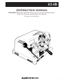
024B
PAGE HEADING
INSTRUCTION MANUAL
IMPORTANT! Read these instructions before you use your new 024B Key Machine.
Ensure that all safety recommendations are followed!
See page 2 for instructions.
1
PAGE HEADING
This manual is registered and applies specifically to the
machine which carries this serial number. It properly
identifies your model and assures you will receive correct
parts, if and when you require replacement parts. Retain
this manual in a safe place. It’s the only one of its kind.
If ownership of this machine is transferred, this service
manual should accompany the machine.
When seeking service information about this machine,
refer to Model No. 024B and the part number desired
(see pages 6 to 8). Note that many parts are not
interchangeable with other ILCO UNICAN machines.
CONTENTS
Warranty ..............................................................................2
Safety information ................................................................3
Introduction / unpacking ......................................................4
Operating parts (illustrated)..................................................5
Operating parts identification (names and part numbers) ..5
Exploded view ......................................................................6
Exploded view parts list........................................................8
Operating handles / test keys / key cutting ..........................9
How to duplicate keys ........................................................10
The cutting operation..........................................................11
Replacing the cutter ............................................................12
Adjustments ........................................................................13
ONE YEAR LIMITED WARRANTY
ILCO UNICAN warrants to the original buyer of any
new model 024B machine that it will repair or
replace, at its option, any part of any machine which
proves, to the reasonable satisfaction of
ILCO UNICAN, to have defects arising from the
faulty manufacture of the machine or from defective
material or components, during a period of one (1)
year from the date of shipment of the machine by
ILCO UNICAN, provided that the machine is
returned by prepaid transport to ILCO UNICAN or to
its authorized representative before the expiry of the
warranty period together with a detailed description
of the alleged defect(s). ILCO UNICAN may, at its
discretion, elect to refund the purchase price
allowable to the part affected, or to issue a credit if
the price therefore remains unpaid.
ILCO UNICAN sells precision-made machines. The
buyer assumes all risks, and ILCO UNICAN shall
not be liable for any reason, if the machine has been
subjected to improper installation, improper use,
improper or inadequate maintenance, negligence, if
any unauthorized modification or alteration is made
to the machine, or in case of accident. For greater
certainty, any machine not operated in accordance
with ILCO UNICAN’s printed instructions or
operated beyond its rated capacity shall not be
covered by this or any other warranty.
2
Any and all warranties made by ILCO UNICAN on
any machine, product, or component thereof shall be
effective only if and for so long as the buyer complies
with all payment obligations pursuant to the buyer’s
accepted and acknowledged order. Failure to meet
such payment obligations shall void all warranties
and not extend the period of time for which such
machine, product of component thereof is warranted
irrespective of whether or not payment is eventually
made.
These warranties are in lieu of and not in addition to
any other warranty of condition, expressed or implied,
including without limitation merchantability, fitness for
a particular purpose or latent defects. The buyer
releases ILCO UNICAN from any liability for any
reason other than a breach of its warranties hereunder.
The liability of ILCO UNICAN shall in no case,
including negligence, exceed the purchase price of
the defective machine, nor shall ILCO UNICAN be
liable for any personal injuries, property damage or
consequential damages.
Use only genuine ILCO UNICAN replacement parts
on this machine!
Serial number : ____________________
WARNING – SAFETY
PAGE HEADING
NOTICE
IMPORTANT - Please read carefully before operating machine.
Safety begins with education, and continues with proper
application. All personnel who operate your machine
should read the supplied Operator’s Manual for
information on how to properly operate it. The likelihood
of accidents and miscuts will be greatly reduced.
General safety
• Safety glasses must be worn to reduce the possibility
of eye injury while operating or in the immediate
vicinity of key cutting equipment.
• Always turn machine off before making adjustments
or inserting or removing keys.
• Machine should be located in an area accessible only
by authorized operators. Location must be such that
customers and other personnel are not subject to
potential injury from “flying chips”.
• Do not defeat safety features built into your machine.
Removal or modification of safety shields, cutter
guards, and other safety devices should be strictly
forbidden.
• At no time should the mechanically-driven parts of
the machine be touched while it is in operation. The
operator should take care to ensure that loose-fitting
clothing, long hair, etc. are kept from the area of
machine operation.
• Your machine has been specially designed and built
for key cutting purposes only and should be operated
according to the Operator’s Manual. All other uses are
strongly discouraged as potentially dangerous, and
should not be attempted! Such use will immediately
void the machine’s warranty.
• Some states have specific age restriction concerning
the operation of certain types of equipment. Check
local and state ordinances for compliance.
Electrical safety
• (120 Volt models) Your machine is designed to
operate using 120 Volt A. C. 60 Hz. electrical current.
It is supplied with a three-prong power plug which
should be used with a properly grounded three-prong
outlet only. Do not defeat the safety purpose of the
plug by modifying or using with non-grounded
outlets!
• To reduce risk of fire or electrical shock, do not expose
or operate machine in damp or wet locations.
• Electrical problems should be referred to qualified
repair technicians. If the machine is under warranty,
contact ILCO UNICAN at the address printed on the
cover. (ILCO UNICAN also offers repair service for
out-of-warranty machines. Contact ILCO UNICAN
for details.)
• Always unplug the machine before removing the hood
or changing the cutter wheel.
Grounding instructions
• In the event of a malfunction or breakdown,
grounding provides a path of least resistance for
electric current to reduce the risk of electric shock.
This machine is equipped with an electric cord that
has an equipment-grounding conductor and a
grounding plug. The plug must be plugged into a
machine outlet that is properly installed and
grounded in accordance with all local codes and
ordinances.
• Do not modify the plug provided - if it will not fit the
outlet, have the proper outlet installed by a qualified
electrician.
• Improper connection of the equipment-grounding
conductor can result in a risk of electric shock. The
conductor with insulation that has a green outer
surface (with or without yellow stripes) is the
equipment-grounding conductor. If repair or
replacement of the electric cord or plug is necessary,
do not connect the equipment-grounding conductor
to a live terminal.
• Check with a qualified electrician or service personnel
if the grounding instructions are not completely
understood, or if in doubt as to whether the machine
is properly grounded.
• Use only 3-wire extension cords that have 3-prong
grounding plugs and 3-pole receptacles that accept
the machine’s plug.
• Repair or replace damaged or worn cords
immediately.
3
PAGE HEADING / UNPACKING
INTRODUCTION
Congratulations!
You’ve purchased a superior key cutting machine.
The Model 024B semiautomatic key machine you've just
purchased incorporates the latest improvements in design for key duplicating machines of its type.
The semiautomatic function of the 024B means that the
machine itself supplies the proper degree of pressure
against the machine’s carriage during the key duplication
process and that the “tracing” motion of the carriage
while duplicating a key is controlled by simply moving a
lever! In essence, the model 024B duplicates keys with
more consistent accuracy and greater speed, especially
important in situations where several employees operate
the machine during the course of the day.
Featuring exclusive four-way vise jaws, the model 024B
is designed to accommodate virtually any standard cylinder key without the need for adapters. Even doublesided automotive keys can be duplicated with ease; the
four-way jaws include stations ideally suited to gripping
these keys and is capable of gripping them in the groove
or milling for enhanced clamping performance when
necessary. (See illustration on page 10).
Unpacking instructions
Your 024B key machine has been shipped to you in a
sturdy, specially-cushioned container to prevent the possibility of damage during handling and shipment. Once
the machine is removed from the carton, it should be set
up on a level workbench and wiped free of all rustproof-
ing oil. The machine is adjusted at the factory and test
keys have been cut on it, but it is recommended that you
check the adjustments to make sure they have not
slipped or shifted during transit (see page 13 “Adjusting
for depth of cut”).
Safety
The 024B has been engineered to duplicate cylinder
(paracentric) keys. It is not intended or designed for any
other purpose. The machine operator assumes all liability when using this machine in a manner inconsistent with
its stated design purpose. Refer to page 3 for complete
safety information before operating the machine.
ILCO UNICAN strongly recommends the use of protective eye glasses or goggles when operating this machine,
CAUTION!
4
or when in the vicinity of the machine while it is being
operated. Protective eye wear prevents injuries! The
machine should be turned off before loading or unloading keys.
When the key machine is operating, be careful not to
contact the vise jaw or carriage against the cutting wheel
as this will cause damage to the cutter, jaw, or carriage.
DO NOT DESTROY OR DISCARD THIS VALUABLE SHIPPING CARTON.
STORE IT CAREFULLY IN A SAFE PLACE. THIS CARTON SHOULD BE USED
WHENEVER THE MACHINE IS MOVED OR SHIPPED.
PAGE
ADJUSTMENTS
HEADING
Adjusting for depth of cut
Adjusting for spacing
To ensure safety, UNPLUG machine from its power
source before adjusting for depth of cut. It's imperative
that the key guide and the cutter be in the same plane,
that is, aligned to each other. If the cutter guide protrudes
further than the cutter, the resulting cuts in a key blank
will be too shallow and the duplicate key will not work.
Likewise, if the cutter guide is behind the cutter, the cuts
in the key will be too deep (see Fig. 9).
There is no adjustment for spacing. However, if a key gauge
assembly is ever replaced, the key gauge must be fitted to
the machine after it has been installed. To do this, first
install a pattern key and key blank and align these against
the cutter guide and cutter. Then lower the key gauge and
file the appropriate finger of the gauge to allow contact with
the shoulder of both keys.
Adjusting the Carriage Stop
Figure 9
Adjustment is
correct when
both key blanks
touch
To check the depth adjustment, insert two identical key
blanks into the vise jaws, setting them flat in each vise.
(It is not necessary to align the blanks.) Then, raise the
carriage, positioning the left blank against the cutter
guide and the right blank against the cutter. Next, turn
the machine pulley by hand and note the right key blank.
The cutter should just barely graze the key blank when
the adjustment is correct.
No cutter is perfectly round so make one complete
rotation of the cutter before changing adjustment. There
will be a high point on the cutter; the adjustment should
be made to the high point. If the cutter does not touch
the key blank after one rotation, proceed to change the
adjustment.
To adjust cutter guide, loosen the binding screw on top of
the guide. With a flat screwdriver, turn adjusting screw in
(to increase depth) and/or out (to decrease depth).
See Fig. 10.
Figure 10
Binding
screw
The purpose of the carriage stop is to prevent the cutter from
hitting into the right vise jaw. The stop is a nut and bolt and
is adjustable (see Fig. 11). To check the adjustment, raise
carriage (without keys in vise jaws) and rotate the cutter by
hand. The cutter should not contact the vise jaw. When the
carriage stop is properly adjusted, there should be a space of
.008" between the vise jaw and the cutter (this is about the
thickness of an ordinary business card). Do not allow a
greater distance since this may affect the depth of cut.
Cleaning
Your machine should be kept clean of all filings and dust.
The most critical areas are the carriage jaws and shafts. A
one inch paint brush is ideal to brush these areas of the
machine. The shafts should be wiped periodically with a
lightly oiled cloth. We suggest brushing the jaws often as
even a single filing can alter the accuracy of the machine.
Lubrication Intervals
Lubricating of moving parts is important. An oil cup is
provided to keep the cutter shaft bearings well lubricated (57 drops of 3-in-1 or lightweight spindle oil in the oil cup is
sufficient.) The carriage spindle should be lubricated with a
thin film of oil and wiped free of chip build up. The
lubrication procedures should be performed every 2-3
weeks depending on usage. The motor requires lubrication
on an annual basis. See motor label for details.
Circuit Breaker
Adjusting screw
(Depth of Cut)
Carriage stop
adjusting screw
To protect against machine damage
in the unlikely event the unit jams
while duplicating a key, your 024B
is equipped with a circuit breaker.
Should it activate, turn the power
switch to the off position, pull the carriage back to the
“load” position , and press the circuit breaker button in to
reset. At this point the machine will run once the power
switch is again placed in the “on” position Repeat the
cutting procedure to complete the unfinished duplicate.
13
PAGECUTTING
THE
HEADING
OPERATION / REPLACING THE CUTTER
General operating sequence
General operating sequence (cont.)
WARNING: Do not install or remove keys unless the
off/on switch is in the off position. Always wear eye
protection when operating this machine!
1. Rotate both vise jaws to the station suitable for the
key being duplicated.
2. Insert the blank key and pattern key into the vise jaw
using the appropriate method described under
“Aligning keys in the vise jaws”. Be sure that both
keys are laying level in the vise jaws and are not tilted.
3. After the keys are
Figure 7
aligned, move the carriage lever to the right
(clockwise) until the
cutter guide is slightly
left of the cut closest to
the head of the pattern
key (See Fig. 7).
4. Press the off/on switch
to the “ON” position.
5. Push down on the
carriage
handle
while pulling out on
the carriage trigger (See Fig. 8).
6. The carriage movement is controlled by the carriage
lever. Using slow to moderate speed, smoothly move
the carriage lever to the left (counter clockwise).
Avoid using an erratic, jerking movement! Once the
cutter is at the tip of the key, move the carriage to the
right by moving the carriage lever clockwise. This will
result in a second cutting pass over the key blank.
STOP before cutter contact with the shoulder of the
blank occurs.
7. Press the off/on switch to the ‘off’ position and
remove finished key by pushing down on the carriage
handle until the trigger clicks into place. Then loosen
wing nut to remove duplicate key.
8. To deburr the key, turn the machine on, and position
the cut key lightly against the rotating deburring
brush.
Figure 8
Carriage
handle
Trigger
(pull out to release)
This will allow you to ease the carriage up into cutting
position. Take care to ensure that the carriage does
not “slam” forward as this will result in probable
cutter damage. Remember, best results are obtained if
the cutter guide makes initial contact slightly left of
the cut closest to the head of the pattern key. Do not
permit the cutter to touch the shoulder of the key
blank.
12
Replacing the cutter
The CU20 cutter used on this machine is 21⁄4" in diameter,
.250" thick (1⁄4") and has a 1⁄2" hole. It's a milling cutter,
made out of high speed steel. It has a flat left side, which
is excellent for making deep cuts, when these cuts are
next to the shoulder, such as on GM, Chicago, etc. No
warranty is placed on the cutter, operators should treat it
with care and avoid harsh usage. Do not force the
carriage up, causing the key blank to bang into the cutter,
and do not apply heavy pressure when cutting. Also, do
not let the cutter cut into the vise jaw; this will dull the
cutter quickly.
As with any metal cutting instrument, the CU20 will dull
with usage. There are three ways to tell when a cutter is
dull and requires replacing:
1. Time - a dull cutter takes longer to make the cuts.
2. Sound - a dull cutter will emit a shrill sound as it runs
across the key blank.
3. Burrs - a dull cutter will not cut away the metal but
will roll it away. When this occurs, there will be a
buildup of metal burrs on the underside of the key. If
this buildup is heavy, the cutter is dull. A sharp cutter
leaves little or no burrs.
To replace cutter, use two wrenches, one 3⁄4" wrench for
cutter nut and one 1⁄2" wrench for cutter shaft. Set the two
wrenches in position and loosen the cutter nut. Note that
the cutter nut has a reverse thread and turns “downward” to loosen. Remove the spacer washer and the dull
cutter. Install the new cutter, the washer and the nut.
OPERATING
PAGE HEADING
PARTS
Safety hood
assembly
Cutter guide
(stylus)
Safety shield
Oil cup
Key gauge
Nylon
brush
CU20 Cutter
Wing nut
Carriage
Carriage
lever
assembly
Circuit
Breaker
On / Off
power switch
Vise jaw
assembly
Trigger
assembly
Carriage
handle
assembly
Operating parts identification
Part no.
Identification
024B-1
024B-3X
024B-8
Carriage
Vise jaw assembly
Wing nut
024B-9X
024B-11X
024B-35X
Carriage handle assembly
Trigger assembly
Carriage lever assembly
024B-38
024B-43
024B-49A
CU20 cutter
Nylon brush
Cutter guide (stylus)
024B-56
024B-61
024B-62A
Key gauge
Circuit Breaker
On/Off power switch
024B-82
024B-86X
024B-87
Oil cup
Safety hood assembly
Safety shield
5
PAGE HEADING
EXPLODED
VIEW
6
THE CUTTING
PAGE
OPERATION
HEADING
Aligning keys in the vise jaws
Keys with shoulders
WARNING: Do not install or remove keys unless
the off/on switch is in the off position.
Both the pattern key and the key blank must be properly aligned and securely clamped in the vise jaws prior to
duplication. The correct procedure to do this follows:
1. Move the carriage lever to the left as far as possible
(See Fig. 3)
Figure 3
Figure 4
2. Assure that both vise jaws are rotated to the correct
position for the type of key being duplicated.
3. Place the key blank in the right hand jaw. Position it
so that it is parallel with the front portion of the jaw
(See Fig. 4). Tighten wing nut lightly.
4. Swing key gauge down to rest on the blade of the key
blank. Slowly move carriage lever clockwise to the
right until the shoulder of the key blank butts up
against the edge of the key gauge (See Fig. 5).
5. Use index finger to press down on the front edge of the
key blank while loosening wing nut. Retighten
securely after assuring that the key blank is contacting key gauge and is properly seated in the vise jaw.
6. Position pattern key in the left vise jaw repeating the
procedure described in step 4.
7. Check to ensure that the pattern key and blank key's
shoulders are snug against the key gauge and both
keys positioned level (not tilted) in the vise jaws.
Return key gauge to the “up” position. The key is now
properly aligned for duplication.
Aligning keys in the vise jaws
Keys without shoulders
On keys that don't have a conventional shoulder, such as
the Ford doublesided key, the tip of the key is used as the
aligning point. With keys of this type follow this
procedure:
1. Assure that both vise jaws are rotated to the correct
position for the type of key being duplicated.
2. Position the key blank in the right hand jaw. For most
tip gauged automotive keys, position the blank so that
the tip is roughly 1/4" left of the jaws right edge.
Tighten the jaws wing nut securely.
3. Move the carriage lever to the left so that the key
gauge's right hand “finger”, with the gauge lowered,
is just forward of the key blank's tip.
4. Insert the customer's key (pattern key) in a similar
manner in the left hand jaw. Then position both the
customer's key and the key blank so that their tips are
both in direct contact with the left edge of the key
gauge fingers (see figure 6).
Figure 6
tip
tip
Figure 5
shoulder
shoulder
Key gauge
Lift up
5. After both the customer's key and blank key are
aligned, lift key gauge to its “raised” position.
6. If a key is cut on both sides, after duplicating “side
one” rotate and proceed with “side two” using the
same alignment procedure. In the case of Ford keys
as well as most doublesided European and Japanese
double sided keys, only the blank needs to be rotated
as the cuts are the same on both sides.
7. Refer to page 12 for additional information covering
the actual key duplicating process.
11
PAGE TO
HOW
HEADING
DUPLICATE KEYS
General key duplication procedures
Using the four-way vise jaws (cont.)
WARNING: Do not install or remove keys unless the
off/on switch is in the OFF position! Always wear eye
protection when operating this machine!
To obtain the best gripping action possible, it is
necessary to assure that the proper vise jaw position is
selected for each key you duplicate. The vise positions
are explained below and proper usage shown in figure 2.
There are four procedures that the machine operator
performs to insure proper duplication of a key:
1. Selection of the proper key blank. Compare the head,
length, and key blank's cross section (width, angle,
and location of grooves) with the key to be duplicated
to assure that a proper match has been made.
2. Ensuring both four-way vise jaws have been placed in
the proper position for the type of key to be
duplicated. See “Using the four-way vise jaws” section of this manual.
3. Proper alignment of the pattern key and blank key
within the vise jaws. See “Aligning keys in the vise
jaws”.
4. Actual duplication of the pattern key; which can be
properly accomplished only after the previous steps
are performed.
Standard - for holding regular cylinder keys, such as
house keys, single sided automotive keys, padlock keys,
with one or two shoulders.
Narrow - for holding the 1092B and other narrow width
keys.
Wide - for holding the Ford double-sided keys and
similar types, either primary or secondary. When positioning the keys in the vise jaws, lay the key so that its
center ledge is flat against the top surface of the jaw.
X - Ideal for holding most double-sided convenience
keys used on most current automobiles. Grip these keys
by the grooves rather than the blade edge where the cuts
are located (see Fig. 2).
Figure 2
Using the four-way vise jaws
Your 024B is equipped with the ILCO UNICAN versatile
Four-way, Super Jaw 2 vise jaws. They feature four
unique clamping surfaces to securely grip virtually any
typical cylinder key (see Fig. 1).
Super Jaw 2
vise jaw shown
gripping a typical
automotive key
Figure 1
Using standard position
Using X position
To reposition the vise jaws, as from Standard to Wide,
Rotate both
jaws as a set
Using wide position
Using narrow position
first loosen the wing nuts. Then lift upward on the top
and bottom of each vise jaw as a complete unit to raise
them above their seat in the carriage. Rotate the jaws
until the chosen vise position is facing toward the rear of
the machine and lower the jaws back into contact with
the carriage. Both left and right vise jaws should be
rotated to the same position.
10
EXPLODED
PAGE HEADING
VIEW
7
PAGE HEADING
EXPLODED
VIEW PARTS LIST
Refer to pages 6-7 for illustration
8
Ref.
Part no.
Description
1
1X
2
3X
024B-1
024B-1X
024B-2
024B-3X
Carriage
Carriage assembly
Carriage stud
Vise jaw assembly
4
6X
8
9X
024B-4
024B-6X
024B-8
024B-9X
11X
16
17
18
Ref.
Part no.
Description
56
57
58
59
024B-56
024B-57
024B-58
024B-59
Key
Key
Key
Key
Vise jaw spring
Thrust bearing set
Wing nut
Carriage handle assembly
60
61
62A
68
024B-60
024B-61
024B-62A
024B-68
Cap screw, 8-32 x 1⁄2"
Circuit Breaker, ETA 1658
On/Off switch
Electrical cover
024B-11X
024B-16
024B-17
024B-18
Trigger assembly
Carriage torsion spring
Washer
Screw, 10-32 x 1⁄2"
70
74
75
79
024B-70
024B-74
024B-75
024B-79
Rubber Mount
Truss head screw, 8-32
Motor, 1⁄4 hp, 115V, C/S
Key gauge spring
20
21
23A
24
024B-20
024B-21
024B-23
024B-24
Cutter shaft bushing
Carriage shaft bushing
Carriage shaft
Pivot Block
82
84
85
86
024B-82
024B-84
024B-85
024B-86
Oil cup
Crescent ring
024B-110V nameplate
Safety hood
25
28A
29A
32
024B-25
024B-28
024B-29A
024B-32
Pinion shaft bushing
Pinion shaft
Set screw, 1⁄4-20 x 5⁄16"
Socket hd. screw, 10-24 x 3⁄8"
86X
87
88
89
024B-86X
024B-87
024B-88
024B-89
Safety hood assembly
Safety shield
Shield screws, 10-32 x 1⁄2"
Flat washer, #10
34
35
35X
36
024B-34
024B-35
024B-35X
024B-36
1
⁄4" lockwasher
Carriage lever
Carriage lever assembly
Cutter nut, N-4
90
91
92
101
024B-90
024B-91
024B-92
024B-101
Nut, #10-32
Power cord
3 wire motor cable
Motor pulley set screw
37
38
40A
41
024B-37
024B-38
024B-40A
024B-41
Cutter spacer
CU20 cutter
Cutter shaft
Cutter shaft pulley
106
109
110
111
024B-106
024B-109
024B-110
024B-111
Chip Tray
Bearing washer
Wave washer
024B Yoke
43
45
46A
47
024B-43
024B-45
024B-46A
024B-47
Nylon brush
Brush bolt washer, 5⁄16
Hex head screw, 5⁄16-18 x 3⁄4
Motor pulley 2" - 3L
112
113
114
115
024B-112 Socket head screw, 10-32 x 3⁄4"
024B-113 Roll pin
024B-114 Torque arm
024B-115 Shoulder screw
48
49A
50
51
024B-48
024B-49A
024B-50
024B-51
V-Belt, 3L-180
Cutter guide (stylus)
Cutter guide roller
Guide roller bushing
160
171
177
178
024B-160
024B-171
024B-177
024B-178
Caution label
Cutter pulley set screw, 3⁄8" -18
Ext. retaining Ring
Washer
52
53
54
55
024B-52
024B-53
024B-54
024B-55
Socket head screw, #8-32 X 15⁄8"
Cutter guide binding washer
Cutter guide binding screw
Adjusting screw
179
180
181
182
024B-179
024B-180
024B-181
024B-182
#10-32 x 3/4 SCHS
Mount Plate
Key Gauge Spacer - Left
Key Gauge Spacer - Right
183
184
185
IM
024B-183
024B-184
024B-185
024B-IM
1/4-20 Lockwasher
1/4-20 Hex Nut
Plate - Chip Guard
Instruction manual
NS
024B-240 220V 1⁄4 HP motor
gauge
gauge bracket
gauge dowel pin
gauge housing (two)
OPERATING HANDLES / TEST KEYSPAGE
/ KEY HEADING
CUTTING
Operating handles
Proper key cutting techniques
The 024B key machine is shipped completely assembled
except for the carriage handle and the lever handle.
Upon unpacking the machine, locate the carriage handle
and thread it into the carriage in the area directly above
the trigger assembly. Then, cut the nylon band holding
the carriage rigid and insert the lower end of the lever
handle into the hole in the pinion shaft (located at the
front of the machine on the left side). Tighten the set
screw on the front of the pinion shaft to secure the lever
handle, Refer to page 5 if unsure of handle placement.
Even though your 024B key machine is designed to
make key cutting fast, easy and accurate, operator technique is important. The actual mechanics of placing keys
within the vise jaws are simple to learn, but there are
some basics that must be followed. A properly adjusted
key machine used by someone who ignores good key
cutting technique will NOT produce a good key. The way
a person clamps a key into the vise jaws is critical to the
accuracy of the duplicated key.
Test keys
A series of cut keys are supplied with your machine.
These keys were cut on your machine and represent the
result of our quality inspectors' work before approving
your machine for shipment. The keys are reproductions
of factory-dimensioned pattern keys and are accurate to
.002" or less. Save these keys and use them as standards
to check the accuracy of cuts in the keys you make. By
measuring across the cuts with a micrometer, you'll be
able to see if your machine is cutting too deep or too
shallow, thus indicating that an adjustment of the cutter
guide is necessary.
Remember - the real purpose of a duplicate key is to
operate the lock for which it was intended. If customers
return keys, you should reexamine your cutting techniques and adjustment of the machine.
Here are some important operating tips:
1. Vise jaws - clean them regularly so that no metal
chips lie under the keys. It is essential that both keys
lie flat across the entire width of each vise jaw.
Neither key should be tilted.
2. Do NOT use pliers or other tools to tighten the vise
jaws. Firm hand pressure is sufficient.
3. Keep the carriage shaft free of metal chips. A thin film
of oil can be applied to it. The carriage should be free
to move without binding.
4. NEVER touch the shoulder of a key to the side of the
cutter guide. This will cause the shoulder of the key
blank to touch the side of the cutting wheel. When
this happens, some of the metal will be cut away from
the shoulder of the key blank. If the resulting
duplicated key is duplicated two, three, four times
over, an error will accumulate and cause a nonoperating key. Do not grind away the shoulder.
5. Don't run the cutter into the vise jaw; this will dull the
cutter, and reduce cutter efficiency.
6. Keep the cutter clean. Don't let any foreign objects or
instruments blunt it. This cutter is a precise cutting
tool and should be handled with care.
7. Lubricating of moving parts is important. An oil cup is
provided to keep the cutter shaft bearings well
lubricated. (5-7 drops of 3-in-1 or lightweight spindle oil
in the oil cup is sufficient.) The carriage spindle should
be lubricated with a thin film of oil and wiped free of
chip build up. The lubrication procedures should be
performed every 2-3 weeks depending on usage. The
motor requires lubrication on an annual basis. See
motor label for details.
9
14
15
USA
ILCO UNICAN CORP.
400 Jeffreys Rd., Rocky Mount, NC 27802-2627
Tel.: (919) 446-3321 • (919) 446-4702
After March 22, 1998 area code changes to 252
Canada and international
ILCO UNICAN INC.
7301 Decarie Blvd., Montreal, Quebec H4P 2G7
Tel.: (514) 735-5411 • (514) 735-4704
Export Fax: (514) 735-1393
Printed in USA
125000
16