1
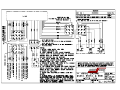
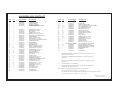
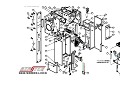
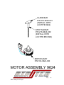
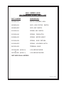
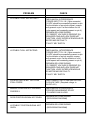
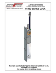
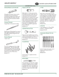
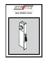
9624 SERIES LOCK
9624 SERIES LOCK PARTS LIST
ITEM
1
2
3
4
4
5
6
7
8
9
10
11
12
13
14
15
16
17
17
18
19
20
21
22
23
24
25
26
27
28
29
31
32
33
34
35
36
37
38
39
40
41
QTY
PART NUMBER
DESCRIPTION
1
1
1
1
1
1
2
1
1
1
1
1
1
2
2
1
1
1
1
1
1*
1*
19
2
1
2**
4**
1
3***
3
2
2
1
2
13
2**
2**
1
1
1
1
1
216-9600-070
216-9400-022
216-9400-026
216-9600-133
146-9600-035
216-9600-134
146-9600-034
316-0000-059
310-0440-027
216-9624-014
146-9624-000
316-0000-063
313-0000-093
146-9600-008
216-9600-115
310-0832-010
310-1032-020
160-9600-004
315-0000-040
216-9600-072
216-9600-111
216-9600-123
216-9600-075
216-9600-074
310-0632-007
310-0000-034
160-9624-000
160-9600-000
319-0000-052
146-9600-010
319-0000-045
310-0632-021
216-9600-081
216-9624-013
310-1032-027
310-0832-021
310-0000-009
310-0632-023
310-0632-022
216-9600-082
216-9600-087
216-9600-088
216-9600-094
216-9600-078
LOCK BODY FRAME
SPRING, TORSION
SPACER, LATCHBOLT
LATCHBOLT,
RH (SHOWN)
ASSY,
LATCHBOLT,
RH (SHOWN)
(OR)
LH
(OR)LATCHBOLT,
ASSY, LATCHBOLT,
LH
ROLL PIN, 1/8 X 1/2
SCREW, SHCS, 4-40 X 3/8
MOTOR MOUNT, UPPER
ASSY, SLIDE
DOWEL PIN, 5/16 X 1 1/4
WASHER, .317 ID X 505 OD X .030
ASSY, DEADLATCH ROLLER BOLT
DEADLOCK ARM
SCREW, SHCS 8-32 X 1/4
SCREW, SHCS, 10-32 X 2 1/2
ASSY, LOCK STATUS SWITCH (3 WIRE)
SPRING, DEADLATCH
RACK (SHOWN)
(OR) RACK, ELHB
MOUNTING PLATE
MOGUL CYLINDER PLATE, RH
MOGUL CYLINDER PLATE, LH
SCREW, FH SOC., 6-32 X 5/16
SCREW, BH SOC., 6-32 X 3/16
ASSY,STEPPER MOTOR
ASSY, KEY SWITCH
SPACER, KEY SWITCH
ASSY, GEAR
SPACER, GEAR
SCREW, SHCS, 6-32 X 7/8
GEAR SUPPORT PLATE
STANDOFF, MOTOR MOUNT PLATE
SCREW, SHCS, 10-32 X 3/16
SET SCREW, 8-32 X 3/4
SCREW, FH SOC., 10-32 X 1/2
SCREW, SET, 6-32 X 3/8
SCREW, SHCS, 6-32 X 1/2
BACK PLATE
RIGHT SIDE COVER
LEFT SIDE COVER
SLIDE COVER
HOUSING COVER
ITEM
QTY
42
43
44
44
44
45
46
47
48
49
50
51
52
53
54
55
56
57
58
59
61
62
63
64
1
1
1****
1****
1****
1
2**
2**
1****
1****
1
2****
2
6*****
1
2
3
1
2****
2
1
1
1
1
*
.
**
PART NUMBER
216-9600-108
315-0000-059
146-9600-028
216-9600-091
216-9600-090
216-9600-086
315-0000-041
216-9600-083
315-0000-053
216-9600-104
340-0000-205
310-0632-024
310-0000-014
310-0256-002
216-9500-025
313-0000-072
340-0000-064
SEE WIRING DIAGRAM
313-0000-092
319-0000-064
319-0000-062
160-9624-001
216-9624-001
216-9624-009
DESCRIPTION
WIRE COVER
SPRING, SLIDE RETURN
ASSY, HOLDBACK LATCH, KBS (SHOWN)
(OR) HOLDBACK LATCH, RH
(OR) HOLDBACK LATCH, LH
MOTOR MOUNT PLATE
SPRING, KEY SWITCH
KEY SWITCH ACTUATOR
SPRING, HOLDBACK LATCH
RLB LATCH
SPLIT LOOM, 5"
SCREW, BH SOC., 6-32 X 1/4
SCREW, SHCS, 2-56 X 3/8
SCREW, SHCS, 2-56 X 9/16
INSULATOR PAD
WASHER, PLASTIC
WIRE TIE (PART NOT SHOWN)
ASSY, 9 PIN MOLEX CONNECTOR
FLAT WASHER, #6, TYPE A
SPACER, KEY SWITCH ACTUATOR
STEM BUMPER (PART OF ITEM #8)
WIRE HARNESS, 9624
GUIDE BAR
STOP SLEEVE
KEYED ONE SIDE MODELS USE P/N 216-9600-076, MOGUL CLYINDER PLATE,
BLANK ON SIDE NOT KEYED.
DIVIDE QTY BY 2 FOR KEYED ONE SIDE MODELS. PART NOT PRESENT ON
ALL MODELS.
***
QTY VARIES. KEYED ONE SIDE MODELS WITH MOGUL CYLINDER PLATE, LH
USE QTY OF 6.
****
PART NOT PRESENT ON ALL MODELS.
***** QTY VARIES. MODELS WITH KEY SWITCH ONE SIDE USE QTY OF 4. MODELS
WITHOUT KEY SWITCH USE QTY OF 2.
NOTE A: WHEN A NEW MOTOR IS REQUIRED, ORDER P/N 146-9624-005.
P/N 146-9624-005 CONTAINS ITEMS 6, 7, 23, 60, 63, & 64.
FOR OLDER LOCKS USING UPPER AND LOWER MOTOR MOUNTS, ORDER P/N 146-9624-006.
P/N 146-9624-006 CONTAINS ITEMS 6, 7, 23, 60, 63, 64, & 31.
9624 Parts List 2-7-2000.pm6
9624 Assy 2-7-2000.eps
Rev. 12-19-2005 9624 Service.pdf
59 47
36
18
46
59
58
57
25
27
33
42
25
24
28
29
46
50
53
1
53
34
55
29
34
B
21
24
55
26
15
20
27 17
11
39
52
54
21
32
16
37
10
19
44
B
48
2
63
64
21
3
9
34
RH
34
21
4
5
40
22
7
A
31
21
41
49
21
SEE NOTE A
8
REQUIRED
51
22
9624 SERIES LOCK
23
6
34
38
31
61
43
A
62
45
GUIDE BAR
P/N 216-9624-001
(INSTALL WITH
LOCTITE #262)
STOP SLEEVE
P/N 216-9624-009
(INSTALL WITH
LOCTITE #RC/680)
MOTOR ASSY
P/N 160-9624-000
MOTOR ASSEMBLY 9624
Motor Assy 9-2-03.eps
9624 SERIES LOCK
RECOMMENDED SPARE PARTS LIST
PART NUMBER
DESCRIPTION
160-9624-000
MOTOR ASSEMBLY, 9624
160-9600-004
ASSY, LOCK STATUS SWITCH
160-9600-000*
ASSY, KEY SWITCH
315-0000-041
SPRING, KEY SWITCH
315-0000-040
SPRING,
216-9624-005
SPRING, MOTOR ASSIST
315-0000-059
SPRING, SLIDE RETURN
315-0000-053*
SPRING, HOLDBACK LATCH
340-0000-209
TERMINAL, MALE
125-0000-096 (96-241-0)
or
125-0000-096 (96-241-1)
L.I.M. MODULE W/RLB
DEADLATCH
L.I.M. MODULE WO/RLB
*NOT USED ON ALL MODELS
9624 Pages 11-19-99.pm6
LOCK MAINTENANCE INFORMATION
ELECTRO-MECHANICAL LOCKING DEVICES
A. Lubrication and cleaning
1. Each lock is well lubricated at the time of assembly. However,
all lubricants deteriorate eventually and need replacing on a
regularly scheduled basis in order to prevent equipment failure.
Airteq Systems recommends cleaning and lubricating each type
of lock according to the following instructions approximately
every (2) years. (Yearly for locks in high use areas).
9424 SERIES LOCK:
Remove the side cover plate and lubricate the angled ramp surface
on the sideplate that the deadlatch bolt dowel pin rides against.
Lubricate the stop side of the deadlatch bolt (back side). When
replacing the side cover, hold the bolt slightly retracted by rotating
and holding the manual release mechanism gear with one finger.
This insures that the deadlatch limit switch operating lever will
not be trapped between the cover and the actuator plate. The
lower lock mechanism should be checked and cleaned once a year
(or more often if if special conditions exist) for accumulated dirt
and other debris that would interfere with proper operation.
Lubrication of upper lock mechanism is not necessary nor
recommended.
9624 SERIES LOCK:
Remove the slide cover. Remove the housing cover. Remove the slide
assembly. Clean and re-lubricate the slide with a thin coating of
recommended lubricant on the following surfaces:
a.) The 45º angled surface that contacts the deadbolt.
b.) The flat "shelf" that lifts the back of the latchbolt.
c.) The two small areas where the slide contacts the back wall
of the slide cavity.
d.) The edges of the two "rails" which contact the side of the
right side cover.
e.) The front and rear faces of the slide which contact the slide
cavity walls.
When replacing the slide assembly, hold the latchbolt retracted into
the lock housing while inserting the slide assembly near the top
of the cavity so that it drops in above the lock status switch lever arm
and not on top of it. Replace the housing cover and slide cover and
fasten securely.Lubrication of the upper lock mechanism is not necessary
nor recommended.
9724 SERIES LOCK:
Remove one side cover plate and lubricate the deadbolt shaft and
cam surface. Lubricate the latchbolt shaft and the stop sides of both bolts.
9724P SERIES LOCK: (PARACENTRIC KEYING)
Remove one side cover plate and lubricate the deadbolt shaft and
cam surface. Lubricate the latchbolt shaft and the stop sides of both bolts.
KEYS AND LEVER TUMBLERS:
1) Key wear can cause improper operation of the lock and may damage
the lock's lever tumblers. Keys in constant use should be periodically
compared to a similar new key. When grooves due to wear are noted in
the steps on the key bit, the old key should be replaced.
2) When rekeying is performed, new tumbler stacks should be purchased
as a set including a new key. This enables Airteq to maintain complete
keying records.
WARNING:
1) Never use WD40 or similar silicone based lubricants.
2) Never use graphite powder as a lubricant.
3) Never lubricate the lever tumblers.
ALL LOCKS:
Lubricate the beveled surfaces of all lock bolts with stick lubricant
as required.
2. RECOMMENDED LUBRICANTS:
Multipurpose teflon based grease: Lubricate internal moving parts with
SYNCO SUPER LUBE WITH TEFLON or equivalent.
Stick lubricant: Lubricate the beveled surfaces of all latch bolts and strikes
with stick lubricant as required. Use PANEF WHITE STICK LUBRICANT
WITH SILICONE or equivalent.
B. Electrical:
1. The electrical system of this lock is operated on regulated 24VDC
(± 2 V) current. Any other voltage or current condition is not acceptable.
9000 Series Lock Maint 1-7-2000.pm6
TROUBLESHOOTING
9424, 9524, 9624 AND 9724 LOCKS
If the lock is not working properly, the following chart may be
used as a guide to locate and correct the problem.
Because the lock receives its signal from the electronic control
system, a thorough check of the control system should be conducted. Using a volt/ohm meter known to be accurate, verify the
correct power signal input at the appropriate connector pin. If the
proper electronic signal is not evident, begin checking “ upstream “ from the connector. If the electronic signal input is
correct, the problem is within the locking device, use the following chart to locate and correct the problem.
The recommended voltage at the lock is 24 VDC ±2V. If the correct
voltage is not evident, begin checking “upstream” from the lock.
If the voltage is correct, the problem is within the locking device
or it's logic interface module, use the following chart to locate
and correct the problem.
PROBLEM
CHECK
LATCHBOLT WILL NOT RETRACT
*MECHANICAL INTERFERENCE
*POWER INPUT TO L.I.M. (12pin connector)
(24 VDC should be momentarily present on pin
2 at the initiation of an unlock request, momentarily present on pin 3 at the initation of a full
cycle request and constantly present on pin 4.)
*BROKEN OR LOOSE WIRING
*IF CORRECT VOLTAGE IS PRESENT ON
REQUIRED PINS AND LOCK DOES NOT
FUNCTION, LOGIC INTERFACE MODULE OR
MOTOR MAY BE FAULTY.
*FAULTY KEY SWITCH
LATCHBOLT WILL NOT EXTEND
*MECHANICAL INTERFERENCE
*POWER INPUT TO L.I.M. (12pin connector)
(24 VDC should be momentarily present on pin
1 at the initiation of an lock request, momentarily present on pin 3 at the initiation of a full
cycle request and constantly present on pin 4.)
*BROKEN OR LOOSE WIRING
*IF CORRECT VOLTAGE IS PRESENT ON
REQUIRED PINS AND LOCK DOES NOT
FUNCTION, LOGIC INTERFACE MODULE
OR MOTOR MAY BE FAULTY.
*FAULTY KEY SWITCH
LOCK RETRACTS BUT WITH LOW
STALL FORCE
*BAD CONNECTION TO ONE MOTOR COIL.
*LOW VOLTAGE. (Required voltage is
24 VDC ±2V)
MANUAL OVERRIDE NOT WORKING
PROPERLY
*MECHANICAL INTERFERENCE
*PROPER ENGAGEMENT OF KEY
CYLINDER CAM IN LOCK
DOOR POSITION SIGNAL NOT GIVEN
*BROKEN OR LOOSE WIRING
(SEE WIRING DIAGRAM)
LATCHBOLT POSITION SIGNAL NOT
GIVEN
*BROKEN OR LOOSE WIRING
(SEE WIRING DIAGRAM)