1
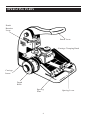
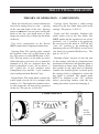
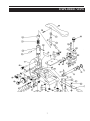
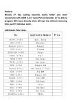
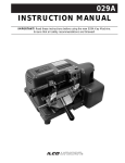
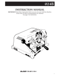
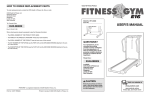
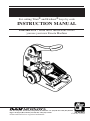
EXACTA MKIII
For cutting Titan¨ and Kwikset¨ keys by code
INSTRUCTION MANUAL
IMPORTANT! Read these instructions before
you use your new Exacta Machine
®
USA: 400 Jeffreys Rd., P.O. Box 2627, Rocky Mount, NC 27802-2627 • Tel.: (919) 446-3321 • FAX: (919) 446-4702
Export: 7301 Decarie Blvd., Montreal, Que. H4P 2G7 • FAX: (514) 735-8707
¨Titan and Kwikset are registered trademarks.
Code No. 125321
This manual applies specifically to the
MKIII model Exacta. It identifies the
MKIII model and assures you will receive
correct replacement parts, if or when they
are required. Retain this manual in a safe
place for future reference. If ownership of
this machine is transferred, this service
manual should accompany the machine.
When seeking service information about
this machine, refer to the model no. (Exacta
MKIII), the machine serial number (located
on the bottom of the unit) and the part
number desired (See pages 7-8 ). Note that
Exacta MKI and MKII parts and accessories are not interchangeable with the
Exacta MKIII.
CONTENTS
Warranty ..................................................................................................2
Introduction to the Exacta ......................................................................3
Operating Parts (Illustrated)....................................................................4
The Cutting Operation - Theory of Operation - Components ................5
The Cutting Operation - Operating the Exacta ......................................6
Exploded View ........................................................................................7
ONE YEAR LIMITED WARRANTY
ILCO UNICAN warrants to the original buyer of any
new model Exacta machine that it will repair or replace, at
its option, any part of any machine which proves, to the
reasonable satisfaction of ILCO UNICAN, to have defects
arising from the faulty manufacture of the machine or from
defective material or components, during a period of (1)
year from the date of shipment of the machine by ILCO
UNICAN, provided that the machine is returned by prepaid
transport to ILCO UNICAN or to its authorized representative before the expiry of the warranty period together
with a detailed description of the alleged defect(s). ILCO
UNICAN may, at its discretion, elect to refund the purchase price allocable to the part affected, or to issue a credit if the price therefore remains unpaid.
ILCO UNICAN sells precision-made machines. The
buyer assumes all risks, and ILCO UNICAN shall not be
liable for any reason, if the machine has been subjected to
improper installation, improper use, improper or inadequate maintenance, negligence, if any unauthorized modification or alteration is made to the machine, or in case of
accident. For greater certainty, any machine not operated
in accordance with ILCO UNICAN's printed instructions
or operated beyond its rated capacity shall not be covered
by this or any other warranty.
Any and all warranties made by ILCO UNICAN on any
machine, product, or component thereof shall be effective
only if and for so long as the buyer complies with all payment obligations pursuant to the buyer's accepted and
acknowledged order. Failure to meet such payment obligations shall void all warranties and not extend the period
of time for which such machine, product or component
thereof is warranted irrespective of whether or not payment is eventually made.
These warranties are in lieu of and not in addition to any
other warranty of condition, expressed or implied, including without limitation merchantability, fitness for a particular purpose or latent defects. The buyer releases ILCO
UNICAN from any liability for any reason other than a
breach of its warranties hereunder.
The liability of ILCO UNICAN shall in no case, including negligence, exceed the purchase price of the defective
machine, nor shall ILCO UNICAN be liable for any personal injuries, property damage or consequential damages.
Use only genuine ILCO UNICAN replacement parts on
this machine!
Registration and Serial number is:_____________________________________
2
INTRODUCTION
Congratulations!
You've purchased a superior key cutting machine.
The Exacta MKIII is a portable, hand operated key machine, specifically designed and
engineered to cut TITAN¨ and Kwikset¨
non-Titan Kwikset keys. This is accomplished thanks to a unique dual-position
punch which allows for instant changeover
from one cut type to the other.
The Exacta MKIII is easy-to-use and maintain. If proper care is taken, your machine
will give years of trouble-free service and
will be a long-lasting investment.
The only maintenance necessary is to keep
the Exacta MKIII and its parts free of dust
and brass chips by regularly cleaning with a
soft brush. Lubrication is normally not necessary.
keys by code, without electrical power. It
will cut these type keys by number, according to the manufacturer's depth and spacing
specifications. A pattern key is not needed
since this machine is not a key duplicator.
The Exacta MKIII is the only machine of
its kind available that can produce the
unique 90¡ cut found in the first spacing
position of a TITAN key as well as the ÒstandardÓ type cuts used in positions 2-6 and on
UNPACKING INSTRUCTIONS
Your new Exacta MKIII code cutting
machine has been shipped to you in a sturdy carton designed to protect it from damage. The unit has been fully tested prior to
shipment, and as packed, is ready for use.
Please familiarize yourself with the operating parts of the unit as shown on page 4
before proceeding to the Operating
Instructions.
3
OPERATING PARTS
Punch
Rotation
Lever
Punch Lever
Carriage Clamping Knob
Carriage
Insert
Depth
Knob
Spacing
Plate
4
Spacing Lever
THE CUTTING OPERATION
THEORY OF OPERATION - COMPONENTS
Carriage insert: Provides a stable resting
surface for the key blank being held in the
carriage. The part no. is P12-21.
There are basically two critical dimensions
involved in cutting a key by code Ñ spacing
of the cuts and depth of the cuts.. Spacing
refers to where the cuts are placed along the
blade of the key and depth refers to how
deeply the notch (cut) is made into the blade
of the key.
Punch and Die assembly: Produces the
actual notch (cut) in the key blank. The
MKIII punch and die operates in one of two
positions; Òcut 1Ó position is for producing
the cut closest to the head of a TITAN key,
Òcuts 2-6Ó position is for producing the
remaining cuts on a TITAN key as well as all
cuts found on a standard Kwikset key. The
part no. is P13-T.
Five basic components on the Exacta
MKIII control these important dimensions:
Spacing Plate: The spacing plate controls
the location of the cuts on the blade of the
key. The part no. for the MKIII plate is P11260. The top surface of the plate has holes
drilled through it and two sets of numerals
stamped on it. The set stamped above the
holes is identified Ò6 pinÓ, the set below Ò5
pinÓ. Utilize the Ò6 pinÓ numbers when
cuttingTitan¨ keys and the Ò5 pinÓ numbers
when cutting standard Kwikset¨ keys.
Shoulder Guide: Located on the left side
of the carriage. After the key blank has been
positioned on the insert, the shoulder guide is
rotated down to form a stop. The key blank is
then pushed to the right until its shoulder
contacts the shoulder guide, at which point
the carriage knob is tightened to secure the
key blank in position. The should guide
MUST be returned to the ÒUPÓ position
before proceeding further with the key
cutting procedure to prevent damaging it.
Depth Knob: The depth knob controls the
actual depth of each cut. It is stamped with
numbers 1-8. The higher the number selected, the deeper the cut that will be produced
on the key. The part no. is P10-GG.
COMPONENTS
Spacing Plate
Depth Knob
Carriage Insert
5
Punch
and Die
Assembly
THE CUTTING OPERATION
OPERATING THE EXACTA
5. Begin the actual cutting procedure by
lifting the spacing lever and positioning it to enter the hole of the spacing
plate marked 1. (Remember, Ò6-pinÓ
for TITAN keys, Ò5-pinÓ for Kwikset
keys.) This is the first spacing position.
The following describes how to operate the
Exacta MKIII to produce a key cut to a specific key bitting number you have chosen.
For the purpose of this example we will
assume that the key to be cut is a TITAN
key, to be bitted 3 - 4 - 4 - 5 - 4 - 2, with the
Ò3Ó being the cut closest to the head of the
key and the Ò2Ó being the cut nearest the tip.
6. Refer to the bitting number specified
for the key to be cut, in this example
3-4-4-5-4-2.
1. Turn punch rotation lever to the Òcut 1Ó
position (required for first cut on
TITAN keys only; cuts 2-6 on TITAN
keys and all cuts on Kwikset keys are
made with the punch rotation lever
in the Òcuts 2-6Ó position).
7. Rotate the depth knob so that 3 appears
next to the index mark on the machine
base. The 3 represents the first number
of the above bitting example. Depress
the punch lever and a no. 3 cut will be
produced in the first spacing position.
Rotate the depth knob to the Ò1Ó position and move the punch rotation lever
to the Òcuts 2 - 6Ó position before producing the remaining cuts on the key.
2. Lift the spacing lever and position it
so that the attached pin enters the
hole designated ÒPÓ on the right side
of the spacing plate. (Remember to utilize the set of numbers above the
indexing holes on the spacing pate,
designated Ò6 pinÓ, when cutting
TITAN keys.)
8. Lift the spacing lever and move it so it's
pin drops into the hole in the spacing
plate marked 2. The key has now shifted to the second spacing position.
3. Rotate the depth knob so that its lowest
number (#1) is next to the index mark
on the machine base.
9. Rotate the depth knob so that 4 appears
next to the index mark on the machine
base. Depress the punch lever and a no.
4 cut will be produced in he second
spacing position;
4. Position the key blank on the carriage
insert, lower the shoulder guide, and
tighten the carriage clamping knob to
secure the key, after first insuring that
the shoulder of the key blank is in
contact with the edge of the shoulder
guide. Return the shoulder guide to
the ÒupÓ position once the key blank
has been clamped in position (very
important).
10. Continue making the remaining four
cuts, 4-5-4-2, in the same manner.
11. Loosen the carriage clamping knob to
remove the completed key.
6
EXPLODED VIEW
7
EXPLODED VIEW
Refer to page 7 for illustration.
Part No.
MKIII-1
MKIII-2
MKIII-3
MKIII-4
MKIII-5
MKIII-6
MKIII-7
MKIII-8
MKIII-9
MKIII-10
MKIII-11
MKIII-12
MKIII-13
MKIII-14
MKIII-15
MKIII-16
MKIII-17
MKIII-18
MKIII-19
MKIII-20*
MKIII-21*
MKIII-22*
MKIII-23*
MKIII-24*
MKIII-25*
MKIII-26*
MKIII-27*
MKIII-28
MKIII-29
MKIII-30
MKIII-31
MKIII-32
MKIII-33
MKIII-34
MKIII-35
MKIII-36
MKIII-37
Description
MKIII Base
Eccentric (MKII)
Eccentric Adjustment Screw
Set Screw
Washer
Retaining Ring
Spring Pin
Retaining Ring
Socket Head Cap Screw
Depth Knob (GG)
Spacing Plate (260)
P12-21 Insert Assembly
Compression Spring
Steel Ball
P12-21 Insert Sub-Assembly
Insert Body (21)
Roll Pin
MKIII Punch & Die Assy.
Rotation Lever
Guide Pin
Punch Spring
Guide Bushing
Die-Sleeve Assembly
MKIII Punch Subassembly
MKIII Punch Body
Spring Pin
MKIII Punch Top
MKII Left Side Shoulder
Guide
Spacing Lever Assembly
Spacing Lever
Flat End Cap (Black)
Dial Pin
Trunnion Nut
Trunnion Washer
Trunnion
Carriage Pin
Retaining Ring
Part No. Description
MKIII-38 MKI/MKII Depth Knob
Detent Assembly
MKIII-39 Plunger Housing
MKIII-40 Plunger
MKIII-41 Snap Ring
MKIII-42 Spring Retainer
MKIII-43 Spring
MKIII-44 Retaining Ring
MKIII-45 Spacing Plate Detent Assy.
MKIII-46 Steel Ball
MKIII-47 Spring
MKIII-48 Retaining Ring
MKIII-49 MKII Carriage Assembly
MKIII-50 MKII Carriage
MKIII-51 Roll Pin
MKIII-52 Clamp Spring
MKIII-53 Clamp
MKIII-54 Shoulder Socket Head Cap
Screw
MKIII-55 Carriage Plate
MKIII-56 Flat Head Screw
MKIII-57 Clamp Screw
MKIII-58 Plastic Box
MKIII-59 Lever (Black)
MKIII-60 Felt Pad
MKIII-61 Lever Screw
MKIII-62 Depth Knob Screw
MKIII-63 Socket Head Cap Screw
MKIII-64 Belleville Washer
MKIII-65 Guide Plate
MKIII-66 Dowel Pin
MKIII-67 Retainer
MKIII-68 #10 Lock Washer
MKIII-69 Spring Pin
MKIII-70 Ball Plunger
MKIII-71 Cut 1 Label
MKIII-72 Cut 2-6 Label
MKIII-73 MKIII Logo Label
* Parts MKIII20 - 27 are not available as separate items. Order MKIII-18 Punch and Die Assembly.
8