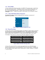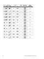
1
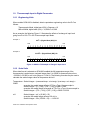
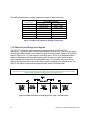
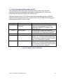
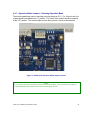
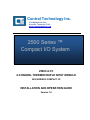
Control Technology Inc. 5734 Middlebrook Pike Knoxville, Tennessee 37921 www.controltechnology.com Toll Free: 800-537-8398 2500 Series ™ Compact I/O System 2500C-8-TC 8-CHANNEL THERMOCOUPLE INPUT MODULE 2500 SERIES® COMPACT I/O INSTALLATION AND OPERATION GUIDE Version 1.0 Copyright© 2014 Control Technology Inc. All rights reserved. This manual is published by Control Technology Inc. (CTI) 5734 Middlebrook Pike, Knoxville, TN 37921. This manual contains references to brand and product names which are trade names, trademarks, and/or registered trademarks of Control Technology Inc. Siemens®, SIMATIC®, and Series 505®, and 505® are registered trademarks of Siemens AG. Other references to brand and product names are trade names, trademarks, and/or registered trademarks of their respective holders. DOCUMENT DISCLAIMER STATEMENT Every effort has been made to ensure the accuracy of this document; however, errors do occasionally occur. CTI provides this document on an “as is” basis and assumes no responsibility for direct or consequential damages resulting from the use of this document. This document is provided without express or implied warranty of any kind, including but not limited to the warranties of merchantability or fitness for a particular purpose. This document and the products it references are subject to change without notice. If you have a comment or discover an error, please call us toll-free at 1-800-537-8398 or email us at [email protected]. Revision 1.0 Date 4/15/2014 REVISION HISTORY Description Initial Release PREFACE This Installation and Operation Guide provides reference information for the CTI 2500C-8TC 8-Channel Thermocouple Module for 2500 Series® Compact I/O system. We assume you are familiar with the operation of CTI 2500 Series® programmable controllers. Refer to the appropriate user documentation for specific information on the 2500 Series® programmable controllers and I/O modules. This Installation and Operation Guide is organized as follows: Chapter 1 provides a description of the module. Chapter 2 covers installation, setup, and wiring. 2500C-8-TC Installation and Operation Guide i USAGE CONVENTIONS NOTE Notes alert the user to special features or procedures. CAUTION Cautions alert the user to procedures that could damage equipment. WARNING Warnings alert the user to procedures that could damage equipment and endanger the user. TABLE OF CONTENTS USAGE CONVENTIONS .........................................................................................II TABLE OF FIGURES ..............................................................................................5 CHAPTER 1 OVERVIEW ......................................................................................6 1.1 1.2 Introduction .....................................................................................................6 Front Panel Description .................................................................................6 1.2.1 1.2.2 1.3 1.4 Asynchronous Operation ...............................................................................7 Modes of Operation........................................................................................7 1.4.1 1.4.2 1.5 1.6 1.7 1.8 1.9 Classic Mode .................................................................................. 8 Classic Plus Mode .......................................................................... 8 Input Signal Ranges .......................................................................................9 Measurement Resolution ...............................................................................9 Accuracy ...................................................................................................... 10 Digital Word map ......................................................................................... 10 Thermocouple Input to Digital Conversion ................................................. 11 1.9.1 1.9.2 1.10 1.11 1.12 Status Display................................................................................. 7 I/O Wiring Connector ...................................................................... 7 Engineering Units ........................................................................... 11 Scale Units...................................................................................... 11 Effect of Out-of-Range Input Signals .......................................................... 12 Error Code Values Reported to the PLC .................................................... 15 Module Setup from the PLC in Classic Plus Mode .................................... 16 CHAPTER 2 INSTALLATION & SETUP.............................................................17 2.1 Installation Planning .................................................................................... 17 2.1.1 2.1.2 2.1.3 2.2 2500C-8-TC Board Layout.......................................................................... 19 2.2.1 2.2.2 2.3 2.4 Operation Mode Jumpers - Selecting Operation Mode ................. 21 Selecting millivolt or Thermocouple Types for Each Channel ...... 22 Factory Default Settings ................................................................. 22 Physical Installation ..................................................................................... 23 Connecting Field Wiring .............................................................................. 24 2.6.1 2.6.2 2.6.3 2.7 Defining Operation Mode and Range Selections .......................... 20 Power Requirements ...................................................................... 20 Unpacking the Module ................................................................................ 20 Configuring the Module ............................................................................... 20 2.4.1 2.4.2 2.4.3 2.5 2.6 Safety Considerations .................................................................... 17 Electrical Interference ..................................................................... 18 Grounding ....................................................................................... 18 Understanding the Modified Front Panel Connector ..................... 25 Connecting Thermocouple Input Wiring ........................................ 25 Connecting the Shield Wiring ......................................................... 26 Installing the Screw Terminal Connector ................................................... 26 2500C-8-TC Installation and Operation Guide 3 2.8 2.9 Calibration of the Module .............................................................................26 Checking Module Operation ........................................................................27 CHAPTER 3 ................................................................................ TROUBLESHOOTING........28 APPENDIX A MODULE SPECIFICATIONS..........................................................31 CTI WARRANTY....................................................................................................33 REPAIR POLICY ...................................................................................................35 4 2500C-8-TC Installation and Operation Guide Table of Figures Figure 1 2500C-8-TC Front Panel ......................................................................................... 6 Figure 2 Asynchronous Operation Diagram ........................................................................... 7 Figure 3 2500C-8-TC Default Configuration Table ................................................................ 8 Figure 4 2500C-8-TC Classic Plus Login Table ..................................................................... 8 Figure 5 2500C-8-TC Classic Plus Configuration Options ..................................................... 9 Figure 6 2500C-8-TC Thermocouple Measurement Ranges ................................................. 9 Figure 7 2500C-8-TC Thermocouple Measurement Resolution Table ................................... 9 Figure 8 2500C-8-TC Accuracy Rating Table ...................................................................... 10 Figure 9 2500C-8-TC Digital Word Map Diagram ................................................................ 10 Figure 10 2500C-8-TC Example of Change in Input Level .................................................. 11 Figure 11 2500C-8-TC Example of Change in Input Level .................................................. 12 Figure 12 2500C-8-TC Effect of Voltage Input on Type J Thermocouple ............................. 12 Figure 13 2500C-8-TC Effect of Voltage Input on Type J Thermocouple ............................ 13 Figure 14 2500C-8-TC Effect of Voltage Input on Type T Thermocouple ........................... 13 Figure 15 2500C-8-TC Effect of Voltage Input on Type E Thermocouple ........................... 13 Figure 16 2500C-8-TC Effect of Voltage Input on Type R Thermocouple ........................... 13 Figure 17 2500C-8-TC Effect of Voltage Input on Type S Thermocouple ........................... 14 Figure 18 2500C-8-TC Effect of Voltage Input on Type N Thermocouple ........................... 14 Figure 19 2500C-8-TC Effect of Voltage Input on mV Input ................................................ 14 Figure 20 2500C-8-TC Error Code Table ........................................................................... 15 Figure 21 2500C-8-TC Word Map for Configuration Data ................................................... 16 Figure 22 2500C-8-TC Binary Example of Module Configuration Word .............................. 16 Figure 23 2500C-8-TC Board Layout Picture...................................................................... 19 Figure 24 2500C-8-TC Operation Mode Jumpers Picture ................................................... 21 Figure 25 2500C-8-TC Jumper Signal Selection Table ....................................................... 22 Figure 26 2500C-8-TC Binary Example of Module Configuration Word .............................. 22 Figure 27 2500C-8-TC Binary Example of Module Configuration Word .............................. 22 Figure 28 2500C-8-TC Default Factory Settings ................................................................. 22 Figure 29 2500C-8-TC Module Physical Installation Picture ............................................... 23 Figure 30 2500C-8-TC Wiring Connector Diagram ............................................................. 24 Figure 31 Millivolt Wiring Connector Diagram .................................................................... 25 Figure 32 Thermocouple Wiring Connector Diagram ......................................................... 25 Figure 33 2500C-8-TC Thermocouple Type and Wire Descriptions .................................... 25 Figure 34 2500C-8-TC LED Error Code Table.................................................................... 27 2500C-8-TC Installation and Operation Guide 5 CHAPTER 1 1.1 OVERVIEW Introduction The CTI 2500C-8-TC Eight-Point Thermocouple Input Module is a member of Control Technology’s family of I/O modules compatible with the Compact System Chassis. It is designed to translate a J, K, T, E, R, S, N thermocouple or millivolt input signal from the field device into an equivalent digital word which is then sent to the programmable controller (PLC). Features 8 Thermocouple inputs Supports Classic and Classic Plus Modes 7 Segment Display for Module Status indication No user calibration Supports J, K, T, E, R, S, & N thermocouples and millivolt inputs Software Configurable Range Selection Uses 2500C-32F-CJC removable wiring connector(sold separately) 1.2 Front Panel Description The module front panel includes a 7-segment status display for showing module status, and a 32-pin removable I/O wiring connector. Status display I/O wiring connector with built in CJC Figure 1 2500C-8-TC Front Panel 6 2500C-8-TC Installation and Operation Guide 1.2.1 Status Display The Status Display will be illuminated with a “0” when the module is functioning normally. If the Status Display is not lit,or if it displaying something other than “0”, refer to Chapter 3 for troubleshooting. 1.2.2 I/O Wiring Connector The 2500C-8-TC utilizes a modified 32 pin connector, part number 2500C-32F-CJC (a standard connector is NOT interchangeable) to provide wiring terminals for Channels 1-8 thermocouple inputs and two temperature (cold junction compensation) sensors. The wiring connector accepts 14-22 AWG wire. 1.3 Asynchronous Operation The module operates asynchronously with respect to the PLC (a scan of the PLC and input sampling of the module do not occur at the same time). Instead, the module will translate all analog inputs in one module update (3.5 milliseconds maximum) and store the translated words in buffer memory. The PLC retrieves the stored words from the module buffer memory at the start of the I/O scan. Figure 2 Asynchronous Operation Diagram 1.4 Modes of Operation The 2500C-8-TC supports two modes of operation: Classic mode and Classic Plus mode. These two modes are selected by jumper JP11 located at the top of the card. Refer to Figure 23 2500C-8-TC Board Layout Picture for the location of this jumper. Classic Mode is the default shipping selection. 2500C-8-TC Installation and Operation Guide 7 1.4.1 Classic Mode In Classic mode (or Low Density) operation, the 2500C-8-TC operates logs in to the PLC as an 8 word Input (8WX) module. Temperature values for each channel are reported to the PLC in the corresponding input word. In Classic mode, the module accepts Type J Thermocouple range. To operate the module in other ranges, you must change to Classic Plus mode. 1.4.1.1 Classic Mode Module Default Configuration The 2500C-8-TC ships in a default configuration which matches a common set of application requirements. 2500-8-TC Default Shipment Settings Operation Mode Classic Mode Logon 8WX Thermocouple J Digital Filtering Enabled Offset Scaling Disabled Temperature Units Degrees C Figure 3 2500C-8-TC Default Configuration Table 1.4.2 Classic Plus Mode In Classic Plus mode (or High Density) operation, the 2500-8-TC operates logs in to the PLC as an 8 word input / 8 word output (8WX/8WY) module. Thermocouple or millivolt signal values for each channel are reported to the PLC in the corresponding input word. The WY output words are used to allow the PLC to select the input signal range for the module. For example, if the module is in Classic Plus mode and is logged in at address 1: WX1 = Channel 1 TC/mV Input WX2 = Channel 2 TC/mV Input t WX3 = Channel 3 TC/mV Input WX4 = Channel 4 TC/mV Input WX5 = Channel 5 TC/mV Input WX6 = Channel 6 TC/mV Input WX7 = Channel 7 TC/mV Input WX8 = Channel 8 TC/mV Input WY9 = Channel 1 Configuration WY10 = Channel 2 Configuration WY11 = Channel 3 Configuration WY12 = Channel 4 Configuration WY13 = Channel 5 Configuration WY14 = Channel 6 Configuration WY15 = Channel 7 Configuration WY16 = Channel 8 Configuration Figure 4 2500C-8-TC Classic Plus Login Table In Classic Plus mode, the PLC can select range operation from any of the following by setting the appropriate bits in the corresponding WY word for each channel. In addition, the PLC can enable or disable digital filtering, Scaling enable or disable, Degrees C or Degrees F for each channel. 8 2500C-8-TC Installation and Operation Guide Thermocouple mVolt J, K, N, R 0-55mV S*, T*, E* *Note: S, T, E also require a jumper selection change from the shipped jumper configuration per channel. Figure 5 2500C-8-TC Classic Plus Configuration Options 1.5 Input Signal Ranges Thermocouple Measurement Ranges J: -210ºC to 760ºC (-350ºF to 1400ºF) K: -270ºC to 1372ºC (-450ºF to 2500ºF) T: -270ºC to 400ºC (-454ºF to 752ºF) E: -270ºC to 1000ºC (-454ºF to 1832ºF) R: 0ºC to 1768ºC (32ºF to 3214ºF) S: 0ºC to 1768ºC (32ºF to 3214ºF) N: -260ºC to 1300ºC (-436ºF to 2372ºF) mV: -55 to +55mV Figure 6 2500C-8-TC Thermocouple Measurement Ranges 1.6 Measurement Resolution The module has a resolution of approximately 0.1oC, 0.1oF or exactly .01 millivolts. The chart below shows the corresponding input resolution per step for each of the input configuration modes: Units Temp: oC Temp: oF Millivolts Input Resolution / Step ~0.05oC ~0.09oF 0.0017 millivolts Figure 7 2500C-8-TC Thermocouple Measurement Resolution Table 2500C-8-TC Installation and Operation Guide 9 1.7 Accuracy The module measurement accuracy is listed below for each Thermocouple Type and millivolt signals: Accuracy : J : +/-1ºC from 0ºC to 60ºC K: +/-1ºC from 0ºC to 60ºC T: +/-1ºC from 0ºC to 60ºC E: +/-1ºC from 0ºC to 60ºC R: +/-2ºC from 0ºC to 60ºC* S: +/-2ºC from 0ºC to 60ºC* N: +/-1ºC from 0ºC to 60ºC mV: +/-0.5% full scale or +/- 500µV * reduced accuracy for measurements below 500ºC Thermocouple Types and mV Figure 8 2500C-8-TC Accuracy Rating Table 1.8 Digital Word map Thermocouple and/or millivolt signals are translated into a 15-bit plus sign digital word. Since the PLC requires a 16-bit input word, the 15-bit value from the converter is placed into a 16-bit word for transmittal to the PLC, the extra bit being used to show the sign of the value. The data is reported to the PLC in the format shown below: Sign bit 16,384 8192 4096 2048 1024 512 256 128 64 32 16 8 4 2 1 Figure 9 2500C-8-TC Digital Word Map Diagram In addition to applying a basic scale of 0-32000, the module provides a over-range error value of 32765 or under-range error value of 32766. 10 2500C-8-TC Installation and Operation Guide 1.9 Thermocouple Input to Digital Conversion 1.9.1 Engineering Units When module SCALING is disabled, data is reported as engineering units to the PLC as follows: Thermocouple Mode, digital word (WX) = Degrees x 10 Millivolt Mode, digital word (WX) = -10,000 to +10,000 As an example, the following Figure 1.3 illustrates the effects of a change in input level going from 0 to 102.4oF in the Thermocouple Input Mode. Example 1: o 0.0 F = (Digital Word (WX))/10 MSB 1 2 0 . 0 . 3 4 5 6 7 8 9 LSB 10 11 12 13 14 15 16 0 . 0 0 0 0 0 0 0 0 0 0 0 . . . 0 . 0 . . . 32 16 8 4 2 1 Example 2: o 102.4 F = (Digital Word (WX))/10 MSB 1 2 0 . 0 . 3 4 5 0 . 0 0 . 6 7 8 9 LSB 10 11 12 13 14 15 16 1 0 0 . 0 0 0 0 0 0 0 0 . . 32 16 8 4 2 1 1024 Figure 10 2500C-8-TC Example of Change in Input Level 1.9.2 Scale Units When data format is selected as SCALING enabled the full temperature range of the thermocouple is scaled as an unsigned integer from 0 to 32000 for thermocouple units or –32,000 to +32,000 for mV units (range of +/-55mV). The following formulas may be used to calculate the scaled integer value for temperature and mV. Temperature: Scaled Integer = (measured temp - min temp) / (max temp - min temp) x 32000 example: the scaled integer offset at 0oC for a Type J thermocouple is: Scaled integer = (0 - (-210)) / (760 - (-210)) x 32000 = 6928 example: the scaled integer overrange at 770oC for a Type J thermocouple is: Scaled integer = (770 - (-210)) / (760 - (-210)) x 32000 = 32330 mV: Scaled Integer = mV x (32,000 ÷ 55) example: the scaled integer offset at 20 mV is: Scaled Integer = 20 x (32,000 ÷ 55) = ~11636.36 2500C-8-TC Installation and Operation Guide 11 The table below shows the scaling temperature ranges of each probe type. Probe Type J K T E R S N Temperature Range o C F -210 to 760 -346 to 1400 -220 to 1320 -364 to 2408 -230 to 400 -382 to 752 -240 to 700 -400 to 1292 0 to 1768 32 to 3214 0 to 1768 32 to 3214 -200 to 1300 -328 to 2372 o Figure 11 2500C-8-TC Example of Change in Input Level 1.10 Effect of Out-of-Range Input Signals The 2559-TC utilizes the underrange and overrange codes of 32766 and 32765, respectively, to indicate when a channel has reached individual limits. Thermocouple inputs exceeding the ANSI standard for the different types of thermocouples (listed on the following pages in Figures 1.4-1.11) will cause the overrange value, 32765, to be displayed and the maximum temperature for that thermocouple type to be returned. Open thermocouples report temperatures that are out of the allowable range. This condition may occur due to failure of the thermocouple or due to the thermocouple wire being cut or disconnected. The 2559-TC will report an open thermocouple condition within 200 milliseconds. NOTE: The 2559-TC uses the overrange error code, 32765, to indicate an open thermocouple. An open thermocouple condition will report within 200 milliseconds. Figure 12 2500C-8-TC Effect of Voltage Input on Type J Thermocouple 12 2500C-8-TC Installation and Operation Guide Figure 13 2500C-8-TC Effect of Voltage Input on Type J Thermocouple Figure 14 2500C-8-TC Effect of Voltage Input on Type T Thermocouple Figure 15 2500C-8-TC Effect of Voltage Input on Type E Thermocouple Figure 16 2500C-8-TC Effect of Voltage Input on Type R Thermocouple 2500C-8-TC Installation and Operation Guide 13 Figure 17 2500C-8-TC Effect of Voltage Input on Type S Thermocouple Figure 18 2500C-8-TC Effect of Voltage Input on Type N Thermocouple Figure 19 2500C-8-TC Effect of Voltage Input on mV Input 14 2500C-8-TC Installation and Operation Guide 1.11 Error Code Values Reported to the PLC The ‘temperature sensor bad’ code is reported to the PLC when either of the two temperature sensors encapsulated in front panel connector goes bad. This is a rare occurrence, but would yield code 32,761 if it does occur. The math overflow code of 32,763 occurs when the thermocouple type mV and SCALE modes are chosen, and the units tries to report a value under –32,000.The following chart summarizes the 2500C-8-TC error codes: Error Code 32761 Error Bad Temperature Sensor(s) 32763 Math Overflow 32764 32765 EEPROM Error Channel Overrange 32766 Channel Underrange Comment; Corrective Action A temperature sensor (s) in front panel connector is faulty/defective; call CTI for replacement 2500C-8-TC connector, P/N: 2500C-32F-CJC. Low end range of mV/SCALE exceeded; Check process to determine if input is actually low. Determine if mV transmitter is defective. EEPROM Storage Error Input level is above normal input range (see Figures 1.4-1.11 for each thermocouple type); Check process to determine if input is actually high or if the transmitter is defective. Input level is above below input range (see Figures 1.4-1.11 for each thermocouple type); Check process to determine if input is actually low or if the transmitter is defective. Figure 20 2500C-8-TC Error Code Table 2500C-8-TC Installation and Operation Guide 15 1.12 Module Setup from the PLC in Classic Plus Mode When operating in Classic Plus Mode, the module reads setup information that the PLC has stored in the WY word corresponding to each channel. See Section 1.4.2 for module log on example. MSB 1 2 3 4 5 6 7 8 9 10 11 12 13 14 15 LSB 16 0 0 0 0 0 0 0 0 0 0 0 0 0 0 0 0 . . . . . . Not Used Bit 9 through 16 Not Used Figure 21 2500C-8-TC Word Map for Configuration Data Bit 1 – Sets Temperature Measurement Range to Degrees Centigrade or Fahrenheit 0=Centigrade 1=Fahrenheit Bit 2 – Sets Digital Filtering Enabled or disabled 0=Enabled 1=Disabled Bit 3 – Sets Scaling Mode Enabled or Disabled 0=Enabled 1=Disabled Bit 4 and Bit 5 are not used Bit 6 through Bit 8 are used to set the input channel to millivolt ranges or select the Thermocouple Type 000 = 55 millivolts 001 = Type E Thermocouple 010 = Type J Thermocouple 011 = Type K Thermocouple 100 = Type N Thermocouple 101 = Type R Thermocouple 110 = Type S Thermocouple 111 = Type T Thermocouple Binary Examples of the Configuration Word for WY9 (Channel 1) X represents a null location 000x x000 xxxx xxxx 100x x001 xxxx xxxx 100x x010 xxxx xxxx Module is set for ºC, Digital Filtering, Scaling Enable, 55mV Module is set for ºF, Digital Filtering, Scaling Enable, Type E Module is set for ºF, Digital Filtering, Scaling Enable, Type J Figure 22 2500C-8-TC Binary Example of Module Configuration Word 16 2500C-8-TC Installation and Operation Guide CHAPTER 2 INSTALLATION & SETUP The installation of the 2500C-8-TC consists of the following steps: 1) 2) 3) 4) 5) 6) 7) 2.1 Reading this Chapter Installation planning Unpacking the module Configuring the module Physical installation Connecting field wiring Checking operation Installation Planning 2.1.1 Safety Considerations Before installing the module, you must identify the personnel hazards that may be created in the event of a system failure and provide interlocks and safety switches to prevent operation during a system failure. Refer to the NEMA ICS 3-304 Programmable Control Standards. WARNING As a system designer, you should be aware that Control devices can fail in an unsafe condition. Unless you incorporate proper safeguards, malfunction of the controller or associated devices, such as operator interface equipment, could cause sudden equipment startup, shutdown, or other unexpected operation. Such startup or shutdown or unexpected operation could result in death or serious injury to personnel, and/or damage to equipment. If you or your company are using CTI controllers with equipment that requires the presence of a person (such as an operator or attendant), you should be aware of this potential safety hazard and take appropriate precautions. The precautions below conform to the National Electrical Manufacturers Association guidelines for installation of programmable controllers as recommended in the NEMA ICS 3– 304 Programmable Control Standards. ICS 3-304.81 Safety Recommendations: Consideration should be given to the use of an emergency stop function which is independent of the programmable controller. Where the operator is exposed to the machinery, such as in loading or unloading a machine tool, or where the machine cycles automatically, consideration should be given to the use of an electromechanical override or other redundant means, independent of the programmable controller, for starting and interrupting the cycle. If provision is required for changing programs while the equipment is in operation, consideration should be given to the use of locks or other means of assuring that such changes can be made only by authorized personnel. These recommendations are 2500C-8-TC Installation and Operation Guide 17 intended as safeguards against the failure of critical components and the effects of such failures or the inadvertent errors that might be introduced if programs are changed while the equipment is in operation. Operator Safety Switches Power should be configured so that it can be manually removed from all output devices. You must provide a method that is independent of the control system for disconnecting power from the outputs when a machine is not operating or the operator must reach into the machine. A non-electronic switch or directly wired relay must be used to disconnect the power. Emergency Stop Switch You must provide a method for disconnecting power from the outputs if an emergency situation is encountered with the machine operation. Use a non-electronic switch or relay that is wired external to the controller and that is easily accessible. 2.1.2 Electrical Interference Electrical interference can adversely affect the operation of control equipment. The major sources of electrical interference in an industrial environment are devices that use high voltages and current, such as motors and welders. Electrical interference can be conducted directly through wiring or inducted via electromagnetic coupling. To ensure a reliable control system, you will need to determine the source of the electrical interference and employ suitable techniques to eliminate it. 2.1.3 Grounding It is very important that the all equipment is properly grounded. Lack of proper grounding may cause intermittent or erratic operation or may cause the control system to fail. A properly installed grounding system will provide a low-impedance path to earth ground, which will give all PLC internal filtering devices a good ground return for reference. The earth ground of the building site typically provides reliable grounding; however, if excessive ground current is present, a separate grounding electrode should be installed. A common practice is to provide a central ground bus bar as a single point of reference within each enclosure, connecting all chassis and power supply components to the bus bar. The bus bar is then connected to earth ground. When connecting to the bus bar, use 1 inch copper braid or No. 8 AWG wire. To ensure good connections, scrape paint or other nonconductive coatings away from mounting studs and from enclosure surfaces where mounting bolts and washers make contact. In addition to connecting the controller rack and power supply to earth ground, you must ensure that the power supply, controller and all modules installed in the base are installed securely and that the thumbscrews are tightened. 18 2500C-8-TC Installation and Operation Guide 2.2 2500C-8-TC Board Layout Top of the Module Operation Mode Selection Jumpers LED Display Module Front Panel Backplane Connector Wiring Connector Plug in Channel Range Selection Jumpers Figure 23 2500C-8-TC Board Layout Picture 2500C-8-TC Installation and Operation Guide 19 2.2.1 Defining Operation Mode and Range Selections Before you can install the module, you must review your planned input signals by channel and decide on one the operation modes (Classic or Classic Plus), and the range selections and settings for each input. If your application needs only Type J Thermocouple digital filtering enabled and degree measurements in Centigrade for every channel, then you may use Classic mode. All other ranges and options require the selection of Classic Plus mode and will be configured in your PLC logic. 2.2.2 Power Requirements The 2500C-8-TC module consumes 0.75 watts of +5VDC power. To calculate the total power required for the base, you need to add the power requirements for the other modules you will install in the base. 2.3 Unpacking the Module Open the shipping carton and remove the special anti-static bag that contains the controller. After discharging any static build-up, remove the unit from the static bag. Do not discard the static bag; use it for protection against static damage when the module is not inserted into the I/O base. CAUTION The components on the 2500C-8-TC printed circuit card can be damaged by static electricity discharge. To prevent this damage, the module is shipped in a special anti-static bag. Static control precautions should be followed when removing the module from the bag and when handling the printed circuit card during configuration. 2.4 Configuring the Module Prior to inserting the module in the base, you must first configure it for operation based on your requirements identified in Section 2.2.1 above. Configuration includes selecting operation mode and selecting signal type, digital filtering, scaling and degrees F or C reporting for each channel. In addition, if you have selected Classic Plus mode, you must configure your PLC program to set the necessary bits in the WY word for the module. NOTE Remember the module configuration must be reflected not only in the jumper selections but also in the Channel Configuration Words that is written to the module from the CPU. This requires logic in the application program to make this happen. See section 1.12 Module Setup from the PLC in Classic Plus Mode 20 2500C-8-TC Installation and Operation Guide 2.4.1 Operation Mode Jumpers - Selecting Operation Mode The module operational mode is selecting using the jumper at JP11. For Classic mode, the jumper should be installed at the “C” position. For Classic Plus mode it should be installed at the “CP” position. The module ships from the factory set for Classic mode operation. Figure 24 2500C-8-TC Operation Mode Jumpers Picture NOTE JP1 is used for factory test purposes and should not be populated. If your module has a jumper at JP1 PROGRAM position please remove before inserting the module. 2500C-8-TC Installation and Operation Guide 21 2.4.2 Selecting millivolt or Thermocouple Types for Each Channel Millivolt or Thermocouple Type is set for each channel using the set of jumpers located on the printed circuit board refer to Figure 23 2500C-8-TC Board Layout Picture for the jumper locations. The module ships with the jumpers in “Type J, K, N, MV” position. For Type R, S, T, and E Thermocouples, place the jumper in the position shown in the table below. Note: Each Channel must be configured for the desired range. Jumper Thermocouple Position Type Selection E E J,K,N,MV J, K, N R,S,T R*, S*, T* mVolt 0-55mV Figure 25 2500C-8-TC Jumper Signal Selection Table Figure 26 2500C-8-TC Binary Example of Module Configuration Word Top of the Module Figure 27 2500C-8-TC Binary Example of Module Configuration Word 2.4.3 Factory Default Settings The 2500C-8-TC default configuration as shipped from the factory is listed in the table below: 2500-8-TC Default Shipment Settings Operation Mode Classic Mode Logon 8WX Thermocouple J Digital Filtering Enabled Offset Scaling Disabled Temperature Units Degrees C Figure 28 2500C-8-TC Default Factory Settings 22 2500C-8-TC Installation and Operation Guide 2.5 Physical Installation Remove AC power from the rack. Align the circuit board with the connector next to the power supply. Slide the controller into the rack until the connector seats. Use the thumbscrews to secure the controller in the rack. Figure 29 2500C-8-TC Module Physical Installation Picture IMPORTANT NOTE: The 2500-8-TC is designed to allow “hot-swapping” the module under power in the event that a replacement is needed. When “hot-swapping” the module, use the following procedure. 1. 2. 3. 4. 5. 6. 7. 8. Make sure all field devices connected to the module are placed into a “safe” state Remove the I/O connector from the front of the module Loosen the module retaining screws and remove it from the base Ensure the jumper configuration of the replacement module matches the one just removed Install the replacement module and tighten the retaining screws. The replacement module must be the same model number as the one removed. Reattach the I/O connector to the module Ensure the replacement module is operating properly Remove the field devices from “safe” state 2500C-8-TC Installation and Operation Guide 23 2.6 Connecting Field Wiring Field wiring is connected to the 2500C-8-TC as shown in the connector wiring diagram below. NOTE: For millivolt inputs you may wire to the “TC+” and the “TC-“ connections or use the COM connections to reduce wiring. The “GND” connection is provided for the shield. See 2.6.1 Understanding the Modified Front Panel Connector for a more detailed explanation of the built CJC references. +TC CH1 A1 B1 CJC+ -TC CH1 A2 B2 CJC- +TC CH2 A3 B3 Not Used -TC CH2 A4 B4 GND +TC CH3 A5 B5 Not Used -TC CH3 A6 B6 GND +TC CH4 A7 B7 Not Used -TC CH4 A8 B8 GND +TC CH5 A9 B9 Not Used -TC CH5 A10 B10 GND +TC CH6 A11 B11 Not Used -TC CH6 A12 B12 GND +TC CH7 A13 B13 Not Used -TC CH7 A14 B14 GND +TC CH8 A15 B15 CJC+ -TC CH8 A16 B16 CJC- 2500C-8-TC Wiring Connection Diagram Figure 30 2500C-8-TC Wiring Connector Diagram 24 2500C-8-TC Installation and Operation Guide 2.6.1 Understanding the Modified Front Panel Connector In order to provide the most accurate cold junction compensation and to avoid CJC calibration, the 2500C-8-TC utilizes a modified front panel connector which has two temperature sensors directly set into the connector. These two temperature sensors are encapsulated in connector locations B1 and B2 and B15 and B16 , and are not user serviceable. NOTE: If either of the two temperature sensors fail, an error code of 32,761 will be reported to the PLC and the module front panel LED will display the error code of “F” the modified connector needs replacing. In the unlikely event this occurs, contact CTI for replacement connector part number ‘”2500C-32FCJC” for your replacement front panel connector. 2.6.2 Connecting Thermocouple Input Wiring For thermocouple input circuits, connect the thermocouple wires to the screw terminals, as indicated in Figure 30 2500C-8-TC Wiring Connector Diagram. Insert the wires in the appropriate wiring connections on the front of the connector. When the wires are inserted, tighten the screws. Repeat this procedure for the all thermocouple input channels. Ensure that the proper wire polarity is followed for each of the seven supported thermocouple probe types, as shown in Figure 33 2500C-8-TC Thermocouple Type and Wire Descriptions. See also Appendix C for more detailed information on different thermocouple types. Figure 32 Thermocouple Wiring Connector Diagram Thermocouple Type J K T E R S N Negative (-) Lead Copper-Nickel (Red) Nickel-Aluminum (Red) Copper-Nickel (Red) Copper-Nickel (Red) Platinum (Red) Platinum (Red) Nisil (Red) Figure 31 Millivolt Wiring Connector Diagram Positive (+) Lead Iron (White) Nickel-Chromium (Yellow) Copper (Blue) Nickel-Chromium (Purple) Platinum-13% Rhodium (Black) Platinum-10% Rhodium (Black) Nicrosil (Orange) Figure 33 2500C-8-TC Thermocouple Type and Wire Descriptions 2500C-8-TC Installation and Operation Guide 25 2.6.3 Connecting the Shield Wiring Control Technology Inc. recommends that all wires be shielded twisted pair with a foil wrap shield and a separate drain wire and that they be installed in a metallic conduit. For millivolt applications, use Belden cable 8761 or equivalent which contains a foil wrap shield and a separate drain wire. The shield and the foil wrap should be twisted together and should be terminated at only one end. The other end should be left in an open circuit condition. CTI recommends that the shield be terminated at the PLC end of the signal wire. Special components are installed on the module to aid in the rejection of noise. When entering the industrial cabinet the shield should be routed from the main terminal strip all the way to the PLC. Signal leads that do not maintain a shield from the terminal strip to the PLC act as antennas and are susceptible to radiated and conducted emissions in the cabinet. Unprotected cables may introduce measurement errors in the module. If the installation is in an extremely noisy environment CTI strongly recommends that the shielded wires be terminated to the PLC chassis ground. CTI has exhaustively tested this product to maximize its ability to reject noise from inductive sources as well as showering arcs, fast transients and other high frequency generators and has determined that the best performance results from connecting all shield wires together at the PLC module and terminating this single wire to the chassis ground with a large current capacity conductor. CTI recommends using a #8 gauge wire or larger from the PLC chassis to the earth ground connection. 2.7 Installing the Screw Terminal Connector When all the input signal wires are connected to the screw terminal connector, carefully install the connector on the front of the module. 2.8 Calibration of the Module The 2500C-8-TC Thermocouple Input Module is calibrated at the factory. No further calibration is required. All calibration parameters are stored in non-volatile memory. There are no user adjustments on this product.. 26 2500C-8-TC Installation and Operation Guide 2.9 Checking Module Operation Apply power to the base power supply. The Power Good LED on the power supply should illuminate, indicating that power is being supplied to the base connectors. The Remote Base Controller will take a few seconds to complete the startup sequence. When this is complete, the status indicator on the 2500-8-TC should display a “0”. Any other value displayed indicates the module has detected a problem or error. You must also check that the module is configured in the memory of the PLC. This is important because the module will appear to be functioning regardless of whether it is communicating with the PLC. Status Indicator 0 A B C D E F Comments Normal operation Defective Internal RAM – contact CTI for assistance Defective Flash memory failure – contact CTI for assistance Defective internal MovX – contact CTI for assistance Shared RAM failure – contact CTI for assistance Defective EEPROM contents Calibration Record lost or corrupted Contact CTI for assistance Front Panel Sensor Error or there is no 2500C-32F-CJC installed – Corrective action is to install the CJC wiring connector or if installed replace with a new CJC wiring connector Figure 34 2500C-8-TC LED Error Code Table NOTE: Refer to Hewlett-Packard Applications Note 290 or Omega Temperature Handbook, Volume 26, Section T, for “practical thermocouple measurement” applications. CAUTION: For proper operation, ensure that the 2500C-8-TC and the thermocouple wires are not subjected to drafts or large temperature gradients during operation. NOTE: In the event the 2500C-8-TC detects an onboard module failure, the module will assert the module fail line and report the module failure in the I/O Status Word, which is reported to the PLC CPU. CTI strongly recommends the user application monitor the I/O Module Status Words which are Status Words 11-26. The I/O Module Status Word can be used to report a module failure for an I/O Module in any of the 2500C I/O slots. If a module failure is reported by the status word, the module should be replaced with a working unit and the failed module sent in for repair. NOTE: It may take 15-30 minutes after initial installation for temperature readings to stabilize. 2500C-8-TC Installation and Operation Guide 27 CHAPTER 3 Troubleshooting If the module provides improper readings or the status indicator is not on, use the following chart to determine the appropriate corrective action. See Figure 34 2500C-8-TC LED Error Code Table for additional diagnostic information. Symptom Indicator is not lit. Probable Cause Base or PLC power is off. Corrective Action Turn base or PLC on. Incorrect inputs. Wrong addresses for word input. Check program for correct work input addresses. Read I/O configuration. Not logged in. Calibration Error Input does not work with PID loop or analog alarm block. Value is not reported as integer 0-32,000. Value is too large. Temperature is reported to PLC as value x10. Incorrect values to PLC. (values off by 10-15 degrees) Incorrect configuration Return the module to CTI for calibration. Select SCALE format Divide value by 10 in PLC. Verify channel configuration word Wrong thermocouple type selected by jumpers. 28 2500C-8-TC Installation and Operation Guide 2500C-8-TC Installation and Operation Guide 29 Appendix A Module Specifications Input Specifications Operation Mode Support (See Note 1) Module Logon Classic Mode 8WX 8WX/8WY Module Update Time all modes Digital Filtering Time Constant Classic Plus Mode 9mS 80mS 80mS Thermocouple Measurement Ranges J: -210ºC to 760ºC (-350ºF to 1400ºF) K: -270ºC to 1372ºC (-450ºF to 2500ºF) T: -270ºC to 400ºC (-454ºF to 752ºF) E: -270ºC to 1000ºC (-454ºF to 1832ºF) R: 0ºC to 1768ºC (32ºF to 3214ºF) S: 0ºC to 1768ºC (32ºF to 3214ºF) N: -260ºC to 1300ºC (-436ºF to 2372ºF) mV: -55 to +55mV Accuracy : J : +/-1ºC from 0ºC to 60ºC K: +/-1ºC from 0ºC to 60ºC T: +/-1ºC from 0ºC to 60ºC E: +/-1ºC from 0ºC to 60ºC R: +/-2ºC from 0ºC to 60ºC* S: +/-2ºC from 0ºC to 60ºC* N: +/-1ºC from 0ºC to 60ºC mV: +/-0.5% full scale or +/- 500µV * reduced accuracy for measurements below 500ºC Thermocouple Types and mV Open Thermocouple Detection mV input impedance Repeatability Measurement Units Resolution Less than 1 second 4.4MΩ DC, >10kΩ @ 60Hz ±1ºC, ±2ºF for all Thermocouple Types Degrees C or Degrees F selectable 16 bits (15 bits plus sign) Data Presentation w/scaling enabled 0-32000(temp) -32000 to +32000(mV) Data Presentation w/scaling disabled ºC or ºF x 10 (temp) -10000 to +10000 (mV) Common Mode Rejection Normal Mode Rejection Backplane Power (MAX) Input ESD Protection Isolation Operating Temperature Range Agency Approvals Pending Shipping Dimensions and Weight Storage Temperature Range Relative Humidity 2500C-8-TC Installation and Operation Guide >110db @ 60Hz >60db @ 60Hz, >50db @ 50 Hz 1.25 watts IEC 1000-4-2 Level 4 Channel to Channel 200V± Channel to Backplane 1500VDC 0ºC to 60ºC (32ºF to 140ºF) UL, ULC, UL Class 1, Div 2, CE 223.84mm x 109.86mm x 34.93mm, 0.45kg -40ºC to 85ºC (-40ºF to 185ºF) 5% to 95% (non-condensing) 31 32 2500C-8-TC Installation and Operation Guide CTI WARRANTY Warranty. Control Technology Inc. ("CTI") warrants that this CTI Industrial Product (the "Product") shall be free from defects in material and workmanship for a period of one (1) year from the date of purchase from CTI or from an authorized CTI Industrial Distributor, as the case may be. Repaired or replacement CTI products provided under this warranty are similarly warranted for a period of 6 months from the date of shipment to the customer or the remainder of the original warranty term, whichever is longer. This Product and any repaired or replacement products will be manufactured from new and/or serviceable used parts which are equal to new in the Product. This warranty is limited to the initial purchaser of the Product from CTI or from an authorized CTI Industrial Distributor and may not be transferred or assigned. 2. Remedies. Remedies under this warranty shall be limited, at CTI's option, to the replacement or repair of this Product, or the parts thereof, only after shipment by the customer at the customer's expense to a designated CTI service location along with proof of purchase date and an associated serial number. Repair parts and replacement products furnished under this warranty will be on an exchange basis and all exchanged parts or products become the property of CTI. Should any product or part returned to CTI hereunder be found by CTI to be without defect, CTI will return such product or part to the customer. The foregoing will be the exclusive remedies for any breach of warranty or breach of contract arising therefrom. 3. General. This warranty is only available if (a) the customer provides CTI with written notice of a warranty claim within the warranty period set forth above in Section 1 and (b) CTI's examination of the Product or the parts thereof discloses that any alleged defect has not been caused by a failure to provide a suitable environment as specified in the CTI Standard Environmental Specification and applicable Product specifications, or damage caused by accident, disaster, acts of God, neglect, abuse, misuse, transportation, alterations, attachments, accessories, supplies, non-CTI parts, non-CTI repairs or activities, or to any damage whose proximate cause was utilities or utility-like services, or faulty installation or maintenance done by someone other than CTI. 4. Product Improvement. CTI reserves the right to make changes to the Product in order to improve reliability, function or design in the pursuit of providing the best possible products. 5. Exclusive Warranty. THE WARRANTIES SET FORTH HEREIN ARE CUSTOMER'S EXCLUSIVE WARRANTIES. CTI HEREBY DISCLAIMS ALL OTHER WARRANTIES, EXPRESS OR IMPLIED. WITHOUT LIMITING THE FOREGOING, CTI SPECIFICALLY DISCLAIMS THE IMPLIED WARRANTIES OF MERCHANTABILITY, FITNESS FOR A PARTICULAR PURPOSE, NONINFRINGEMENT, COURSE OF DEALING AND USAGE OF TRADE. 6. Disclaimer and Limitation of Liability. TO THE FULLEST EXTENT PERMITTED BY APPLICABLE LAW, CTI WILL NOT BE LIABLE FOR ANY BUSINESS INTERRUPTION OR LOSS OF PROFIT, REVENUE, MATERIALS, ANTICIPATED SAVINGS, DATA, CONTRACT, GOODWILL OR THE LIKE (WHETHER DIRECT OR INDIRECT IN NATURE) OR FOR ANY OTHER FORM OF INCIDENTAL, INDIRECT OR CONSEQUENTIAL DAMAGES OF ANY KIND. CTI'S MAXIMUM CUMULATIVE LIABILITY RELATIVE TO ALL OTHER CLAIMS AND LIABILITIES, INCLUDING OBLIGATIONS UNDER ANY INDEMNITY, WHETHER OR NOT INSURED, WILL NOT EXCEED THE COST OF THE PRODUCT(S) GIVING RISE TO THE CLAIM OR LIABILITY. CTI DISCLAIMS ALL LIABILITY 2500C-8-TC Installation and Operation Guide 33 RELATIVE TO GRATUITOUS INFORMATION OR ASSISTANCE PROVIDED BY, BUT NOT REQUIRED OF CTI HEREUNDER. ANY ACTION AGAINST CTI MUST BE BROUGHT WITHIN EIGHTEEN (18) MONTHS AFTER THE CAUSE OF ACTION ACCRUES. THESE DISCLAIMERS AND LIMITATIONS OF LIABILITY WILL APPLY REGARDLESS OF ANY OTHER CONTRARY PROVISION HEREOF AND REGARDLESS OF THE FORM OF ACTION, WHETHER IN CONTRACT, TORT (INCLUDING NEGLIGENCE AND STRICT LIABILITY) OR OTHERWISE, AND FURTHER WILL EXTEND TO THE BENEFIT OF CTI'S VENDORS, APPOINTED DISTRIBUTORS AND OTHER AUTHORIZED RESELLERS AS THIRD-PARTY BENEFICIARIES. EACH PROVISION HEREOF WHICH PROVIDES FOR A LIMITATION OF LIABILITY, DISCLAIMER OF WARRANTY OR CONDITION OR EXCLUSION OF DAMAGES IS SEVERABLE AND INDEPENDENT OF ANY OTHER PROVISION AND IS TO BE ENFORCED AS SUCH. 7. Adequate Remedy. The customer is limited to the remedies specified herein and shall have no others for a nonconformity in the Product. The customer agrees that these remedies provide the customer with a minimum adequate remedy and are its exclusive remedies, whether based on contract, warranty, tort (including negligence), strict liability, indemnity, or any other legal theory, and whether arising out of warranties, representations, instructions, installations, or non-conformities from any cause. The customer further acknowledges that the purchase price of the Product reflects these warranty terms and remedies. 8. Force Majeure. CTI will not be liable for any loss, damage or delay arising out of its failure (or that of its subcontractors) to perform hereunder due to causes beyond its reasonable control, including without limitation, acts of God, acts or omissions of the customer, acts of civil or military authority, fires, strikes, floods, epidemics, quarantine restrictions, war, riots, acts of terrorism, delays in transportation, or transportation embargoes. In the event of such delay, CTI's performance date(s) will be extended for such length of time as may be reasonably necessary to compensate for the delay. 9. Governing Law. The laws of the State of Tennessee shall govern the validity, interpretation and enforcement of this warranty, without regard to its conflicts of law principles. The application of the United Nations Convention on Contracts for the International Sale of Goods shall be excluded. 34 2500C-8-TC Installation and Operation Guide REPAIR POLICY In the event that the Product should fail during or after the warranty period, a Return Material Authorization (RMA) number can be requested orally or in writing from CTI main offices. Whether this equipment is in or out of warranty, a Purchase Order number provided to CTI when requesting the RMA number will aid in expediting the repair process. The RMA number that is issued and your Purchase Order number should be referenced on the returning equipment's shipping documentation. Additionally, if the product is under warranty, proof of purchase date and serial number must accompany the returned equipment. The current repair and/or exchange rates can be obtained by contacting CTI's main office at 1-800-537-8398 or go to www.controltechnology.com/support/repairs/. When returning any module to CTI, follow proper static control precautions. Keep the module away from polyethylene products, polystyrene products and all other static producing materials. Packing the module in its original conductive bag is the preferred way to control static problems during shipment. Failure to observe static control precautions may void the warranty. 2500C-8-TC Installation and Operation Guide 35