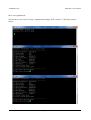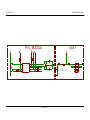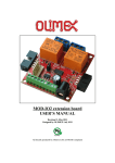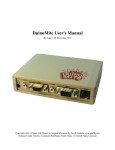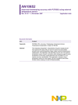
1
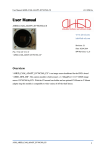
MOD-RTC development board USER’S MANUAL Initial release, May 2012 Designed by OLIMEX Ltd, 2011 All boards produced by Olimex LTD are ROHS compliant OLIMEX© 2012 MOD-RTC User's Manual Disclaimer: © 2012 Olimex Ltd. Olimex®, logo and combinations thereof, are registered trademarks of Olimex Ltd. Other terms and product names may be trademarks of others. The information in this document is provided in connection with Olimex products. No license, express or implied or otherwise, to any intellectual property right is granted by this document or in connection with the sale of Olimex products. Neither the whole nor any part of the information contained in or the product described in this document may be adapted or reproduced in any material from except with the prior written permission of the copyright holder. The product described in this document is subject to continuous development and improvements. All particulars of the product and its use contained in this document are given by OLIMEX in good faith. However all warranties implied or expressed including but not limited to implied warranties of merchantability or fitness for purpose are excluded. This document is intended only to assist the reader in the use of the product. OLIMEX Ltd. shall not be liable for any loss or damage arising from the use of any information in this document or any error or omission in such information or any incorrect use of the product. Thank you for purchasing MOD-RTC development board assembled by OLIMEX LTD Page 2 of 16 OLIMEX© 2012 MOD-RTC User's Manual Table of Contents CHAPTER 1.................................................................................................................5 OVERVIEW.................................................................................................................5 1. Introduction to the chapter.......................................................................................................5 1.1 Features.....................................................................................................................................5 CHAPTER 2 ................................................................................................................6 SETTING UP THE MOD-RTC MODULE...............................................................6 2. Introduction to the chapter.......................................................................................................6 2.1 Electrostatic warning...............................................................................................................6 2.2 Requirements...........................................................................................................................6 2.3 Powering the module...............................................................................................................6 2.4 Duinomite note.........................................................................................................................6 CHAPTER 3.................................................................................................................8 MOD-RTC BOARD DESCRIPTION........................................................................8 3. Introduction to the chapter.......................................................................................................8 3.1 Layout (bottom view)...............................................................................................................8 CHAPTER 4.................................................................................................................9 THE PCF8563 CMOS REAL-TIME CLOCK.........................................................9 4. Introduction to the chapter.......................................................................................................9 4.1 The PCF8563............................................................................................................................9 CHAPTER 5 ..............................................................................................................10 CONTROL CIRCUITY............................................................................................10 5. Introduction to the chapter.....................................................................................................10 5.1 Reset........................................................................................................................................10 5.2 Clock ......................................................................................................................................10 CHAPTER 6...............................................................................................................11 HARDWARE..............................................................................................................11 6. Introduction to the chapter.....................................................................................................11 6.1 BAT connector.......................................................................................................................11 6.2 UEXT......................................................................................................................................11 6.3 Jumper description................................................................................................................12 CHAPTER 7...............................................................................................................13 SCHEMATICS...........................................................................................................13 7. Introduction to the chapter.....................................................................................................13 7.1 Eagle schematic......................................................................................................................13 7.2 Physical dimensions...............................................................................................................15 Page 3 of 16 OLIMEX© 2012 MOD-RTC User's Manual CHAPTER 8...............................................................................................................16 REVISION HISTORY..............................................................................................16 8. Introduction to the chapter.....................................................................................................16 8.1 Document revision.................................................................................................................16 8.2 Web page of your device.......................................................................................................16 Page 4 of 16 OLIMEX© 2012 MOD-RTC User's Manual CHAPTER 1 OVERVIEW 1. Introduction to the chapter Thank you for choosing the MOD-RTC extension module from Olimex! This device is a tiny implementation of NXP's real-time clock/calendar chip PCF8563. The main purpose of MOD-RTC is adding real-time clock to another Olimex board via the UEXT connector without the need of a hardware modification. 1.1 Features • • PCF8536 Real time clock Lithium 3V battery connector • • UEXT connector FR-4, 1.5 mm, soldermask, component print • Dimensions: 40x19mm (1.57 x 0.75") Page 5 of 16 OLIMEX© 2012 MOD-RTC User's Manual CHAPTER 2 SETTING UP THE MOD-RTC MODULE 2. Introduction to the chapter This section helps you set up the MOD-RTC development board for the first time. Please consider first the electrostatic warning to avoid damaging the board, then discover the hardware and software required to operate the board. The procedure to power up the board is given, and a description of the default board behavior is detailed. 2.1 Electrostatic warning MOD-RTC is shipped in a protective anti-static package. The board must not be exposed to high electrostatic potentials. A grounding strap or similar protective device should be worn when handling the board. Avoid touching the component pins or any other metallic element. 2.2 Requirements In order to set up the MOD-RTC, the following items are required: - MOD-RTC module itself - an OLIMEX board to use as a host (Note that it is possible to use another board without UEXT but that might cost you the ease of use – e.g. you will have to manually connect wires in the proper order) Additionally if your host board can't provide 3.3V on the UEXT connector you will need 3V battery able to power the module. 2.3 Powering the module The module is powered either by the UEXT of a host board or by a battery. It required at least 3V. 2.4 Duinomite note Duinomite has prebuilt support for MOD-RTC in firmwares prior to firmware version 3.x. There is a high chance that the support for MOD-RTC is implemented by the time you are reading, however, Page 6 of 16 OLIMEX© 2012 MOD-RTC User's Manual but it is not guaranteed. All you have to do is write “setup” command and change “RTC on Boot”. Check the pictures below: Page 7 of 16 OLIMEX© 2012 MOD-RTC User's Manual CHAPTER 3 MOD-RTC BOARD DESCRIPTION 3. Introduction to the chapter Here you get acquainted with the main parts of the board. Note the names used on the board differ from the names used to describe them. For the actual names check the MOD-RTC board itself. 3.1 Layout (bottom view) Page 8 of 16 OLIMEX© 2012 MOD-RTC User's Manual CHAPTER 4 THE PCF8563 CMOS REAL-TIME CLOCK 4. Introduction to the chapter In this chapter is located the information about the heart of MOD-RTC. The information is a modified version of the datasheet provided by its manufacturers. 4.1 The PCF8563 • • • • • • • • • • • • Provides year, month, day, weekday, hours, minutes, and seconds based on 32.768 kHz quartz crystal Century flag Clock operating voltage: 1.0 V to 5.5 V at room temperature Low backup current; typical 0.25 A at VDD = 3.0 V and Tamb = 25 C 400 kHz two-wire I2C-bus interface (at VDD = 1.8 V to 5.5 V) Programmable clock output for peripheral devices (32.768 kHz, 1.024 kHz, 32 Hz, and 1 Hz) Alarm and timer functions Integrated oscillator capacitor Internal Power-On Reset (POR) I2C-bus slave address: read A3h and write A2h Open-drain interrupt pin For comprehensive information on the PCF8563 visit the NXP’s web page for a datasheet. It is highly recommended to have a look at that datasheet. At the moment of writing the microcontroller datasheet can be found at the following link: http://www.nxp.com/documents/data_sheet/PCF8563.pdf Page 9 of 16 OLIMEX© 2012 MOD-RTC User's Manual CHAPTER 5 CONTROL CIRCUITY 5. Introduction to the chapter Here you can find information about reset circuit and quartz crystal locations. 5.1 Reset The module lacks hardware reset. 5.2 Clock Real time clock (RTC) Q2 is found at pins 1 and 2 of the PCF8563. Page 10 of 16 OLIMEX© 2012 MOD-RTC User's Manual CHAPTER 6 HARDWARE 6. Introduction to the chapter In this chapter are presented the connectors that can be found on the board all together with their pinout. Jumpers functions are described. Notes and info on specific peripherals are presented. Notes regarding the interfaces are given. 6.1 BAT connector 3V battery can be inserted to power the board externally. Insert the battery with its positive side top. 6.2 UEXT MOD-RTC board has UEXT connector and can interface Olimex's UEXT modules. Since MODRTC is configured as a (slave) device it is advisable to be connected to a host device. For more information on UEXT please visit: http://www.olimex.com/dev/OTHER/UEXT.pdf Pin # Signal Name 1 +3.3V 2 GND 3 CLKOUT 4 #INT Page 11 of 16 OLIMEX© 2012 5 SCL 6 SDA 7 NOT CONNECTED 8 NOT CONNECTED 9 NOT CONNECTED 10 NOT CONNECTED MOD-RTC User's Manual 6.3 Jumper description The module doesn't have any jumpers. Page 12 of 16 OLIMEX© 2012 MOD-RTC User's Manual CHAPTER 7 SCHEMATICS 7. Introduction to the chapter In this chapter are located the schematics describing logically and physically MOD-RTC. 7.1 Eagle schematic MOD-RTC schematic is visible for reference here. You can also find them on the web page for MOD-RTC at our site: http://www.olimex.com/dev/MOD-RTC.html. They are located in HARDWARE section. The EAGLE schematic is situated on the next page for quicker reference. Page 13 of 16 OLIMEX© 2012 RTC_MODULE 2V7 2V7 2V7 C1 100nF #INT R8 NA(330R) 4 3 VDD VSS #INT OSCI OSCO SCL SDA CLKOUT PCF8563T/5 1 2 6 5 7 C16 10pF D1 Q2 32768Hz/6pF R6 330R SCL R7 330R SDA R9 CLKOUT NA(330R) C17 NA(10pF) Page 14 of 16 R10 0R 1N4148/SMD GN D + + 8 R5 - U1 R2 UEXT 2V7 NA(2.2k) R1 R4 NA(2.2k) NA(2.2k) 2V7 NA(2.2k) 2V7 MOD-RTC User's Manual 0R(NA) D2 UEXT 1 3 1N4148/SMD CLKOUT SCL 5 7 9 BAT BC-2001(BTH-W39-20-LF) 2 4 #INT 6 SDA 8 10 IDC10S-PCB OLIMEX© 2012 MOD-RTC User's Manual 7.2 Physical dimensions Note that all dimensions are in inches. Page 15 of 16 OLIMEX© 2012 MOD-RTC User's Manual CHAPTER 8 REVISION HISTORY 8. Introduction to the chapter In this chapter you will find the current and the previous version of the document you are reading. Also the web-page for your device is listed. Be sure to check it after a purchase for the latest available updates and examples. 8.1 Document revision Revision Changes Modified Pages A Initial Creation All 8.2 Web page of your device The web page you can visit for more info on your device is http://www.olimex.com/dev/MODRTC.html. There you can find more info and some examples. ORDER CODES: MOD-RTC - completely assembled and tested How to order? You can order to us directly or by any of our distributors. Check our webpage http://www.olimex.com/ for more info. Page 16 of 16