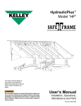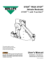
1
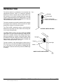
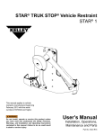
stAR® Truk stop®
Vehicle Restraint
STAR® 1 with Truk Alert®
This manual applies to vehicle
restraints manufactured beginning
February 2013 with the serial
numbers 61070042 and higher.
Do not install, operate or service this product unless
you have read and understand the Safety Practices,
Warnings, and Installation and Operating Instructions
contained in this manual. Failure to do so could result
in death or serious injury.
User’s Manual
Installation, Operations,
Maintenance and Parts
Part No. 5528 R11
Table of contents
Introduction..................................................................2
Safety Signal Words....................................................2
Safety Practices..........................................................3
Introduction . ...............................................................4
Installation...................................................................5
Mounting Considerations........................................5
Tools Required........................................................5
Wedge Anchor Installation (Std. Installation)..........5
Installation with Pit Type Dock Levelers..................7
Installation with EOD Type Dock Levelers............10
Optional Snow Plow Guard Placement.................11
Standard Wall Mounting Procedure......................12
Optional Stanchion Mounting . .............................14
Operation...................................................................15
Operational Checks...................................................17
Parts Replacement Instructions ...............................18
Subframe Reinforcing Kit..........................................19
Parts List...................................................................20
Wiring Diagram . .......................................................23
Pivot Pin Guard Kit Installation Instructions..............24
Warranty Information.................................................27
Distributor Information...............................................28
Introduction
Welcome, and thank you for buying your vehicle restraint from Kelley®.
This User’s Manual contains information that you need to safely install, operate and maintain the vehicle restraint.
It also contains a complete parts list and information about ordering replacement parts. Please keep and read
this User’s Manual before using your new vehicle restraint.
Safety SIGNAL WORDS
You may find safety signal words such as DANGER, WARNING, or CAUTION throughout this Owner’s Manual.
Their use is explained below:
This is the safety alert symbol. It is used
to alert you to potential personal injury
hazards. Obey all safety messages that
follow this symbol to avoid possible death or injury.
Indicates an imminently hazardous situation which,
if not avoided, will result in death or serious injury.
Indicates a potentially hazardous situation which, if
not avoided may result in minor or moderate injury.
Indicates a potentially hazardous situation which, if
not avoided, could result in death or serious injury.
Notice is used to address practices not related to
personal injury.
2
©2013 4Front Engineered Solutions, Inc.
5528 R11 — STAR® 1 with Truk Alert®
February 2013
Safety practices
INSTALLATION, MAINTENANCE AND SERVICE
Read these safety practices before installing, operating
or servicing the vehicle restraint. Failure to follow these
safety practices could result in death or serious injury.
READ AND FOLLOW THE OPERATING INSTRUCTIONS
IN THIS MANUAL BEFORE OPERATING THE VEHICLE
RESTRAINT. If you do not understand the instructions,
ask your supervisor to teach you how to use the vehicle
restraint.
Improper installation of vehicle restraint could result in
death or serious injury to dock workers or other users
of the vehicle restraint.
Be certain to follow the installation instructions in this
manual.
OPERATION
Use by untrained people can cause property damage, bodily
injury and/or death. Your supervisor should teach you the
safe and proper way to use the vehicle restraint. Read and
follow the complete OPERATION PROCEDURE on page 6
before use. DO NOT USE THE VEHICLE RESTRAINT IF
IT IS NOT WORKING RIGHT. Tell your supervisor it needs
repair.
Be certain bystanders in the driveway stand clear when
vehicle restraint is operated.
Do not load or unload any vehicle unless you make certain
the vehicle restraint has securely hitched the vehicle's
Rear Impact Guard (RIG) and set the brakes. If the vehicle
restraint does not hitch the vehicle's RIG for any reason, BE
CERTAIN TO CHOCK THE VEHICLE WHEELS BEFORE
LOADING OR UNLOADING.
If the vehicle restraint does not operate properly using the
procedures in this manual, BE CERTAIN TO CHOCK THE
VEHICLE WHEELS BEFORE LOADING OR UNLOADING.
Call your local Kelley® distributor for service.
Place barricades around pit on dock floor and drive while
installing, maintaining or repairing trailer restraining device.
Do not stand in the driveway between the dock and a backing
vehicle.
Do not use the vehicle restraint as a step.
Do not install the vehicle restraint anchor bolts into aged or
unsound concrete.
Keep hands and feet clear of guide tracks and moving parts
at all times.
Do not weld on ductile iron hook casting (item 2, page 18).
All electrical troubleshooting and repair must be done by a
qualified technician and meet all applicable codes.
Before doing any electrical work (including changing bulbs),
make certain the power is disconnected and properly tagged
or locked off.
If you have any problems or questions, contact your local
Kelley distributor for assistance.
Keep hands and feet clear at all times. Stay clear of vehicle
restraint when it is moving.
Before chocking wheels or engaging vehicle restraint, dump
air from air ride suspensions and set parking brakes.
February 2013
5528 R11 — STAR® 1 with Truk Alert®
©2013 4Front Engineered Solutions, Inc.
3
Introduction
The vehicle restraint is a combination of two separate and
independent products. There is no electrical connection
between the vehicle restraint and the TRUK ALERT. The
hook position of the vehicle restraint does not control the
inside or outside signal lights of the TRUK ALERT. IT IS THE
RESPONSIBILITY OF THE DOCK WORKER TO TURN ON
THE APPROPRIATE SIGNAL LIGHTS.
Fig. 1
Red light
Green light
Driver’s caution sign“MOVE ON GREEN ONLY”
The vehicle restraint is a manually operated vehicle restraint
that requires visual inspection of the hook and rear impact
guard (RIG) to determine a hitched condition.
The TRUK ALERT establishes positive communications
between the dock worker and the vehicle driver through the
use of signs and signal lights.
The TRUK ALERT consists of two sets of red and green
signal lights. One set is mounted inside the building and the
other set is mounted outside of the building. Both sets of
lights are controlled by a switch on the inside lights. When
the green inside light is flashing, the red outside light will
flash. Likewise, when the red inside light is flashing, the
green outside light will flash. See Fig. 1.
The sign mounted on the outside tells the vehicle driver to
back in or pull out only when the GREEN outside signal light
is on. The placard on the wall inside the building tells the
dock worker to enter the vehicle only when the GREEN light
is flashing.
OUTSIDE LIGHTS AND SIGN
Red light
Placard
Green light
Switch
INSIDE LIGHTS AND PLACARD
4
©2013 4Front Engineered Solutions, Inc.
5528 R11 — STAR® 1 with Truk Alert®
February 2013
Installation
Mounting considerations
Before installation read and follow the Safety Practices
on page 3. Failure to follow these safety practices could
result in death or serious injury.
READ AND FOLLOW THE OPERATION INSTRUCTIONS
IN THIS MANUAL BEFORE OPERATING THE VEHICLE
RESTRAINT. If you do not understand the instructions,
ask your supervisor to teach you how to use the vehicle
restraint.
Improper installation of the vehicle restraint could result
in death or serious injury to dock workers or other users
of the vehicle restraint.
Place barricades around pit on dock floor and drive while
installing, maintaining or repairing vehicle restraining
device.
Be certain bystanders in the driveway stand clear when
vehicle restraint is operated.
Be certain to follow the installation instructions in this
manual.
3. Docks 46” and lower may require a specially modified
vehicle restraint or operation of the dock leveler may need
to be restricted. Contact your local Kelley distributor for
information.
4. A 3/8” gap is required between the dock leveler front
angle and pit floor to install the horizontal mounting plate.
If the driveway beneath the vehicle restraint is affected
by frost heave:
1. Raise restraint sufficient distance to prevent damage,
or
2. Modify driveway to provide additional clearance.
Consult registered architect or professional engineer.
Tools required
- Welder
- Impact or rotary drill with 1/2" diameter concrete drill bit
- 9/16” wrench
- General hand tools
- Touch up paint (Gold)
- Torque wrench (45 ft-lb min.)
- Rebar cutting drill bit with rotary only drill motor.
Do not install the vehicle restraint anchor bolts into
aged or unsound concrete.
1. The dock face on which the vehicle restraint will be mounted
must be flat to prevent binding of the mechanism. If the
dock face is not flat it may be necessary to use shims or
physically modify the dock face to provide a flat mounting
surface. If shimming is required it is necessary to shim
behind the pivot pin as well as at the anchor bolts.
Vehicle restraints require a 4" bumper projection from the
front of the bumper to the rear of the back plate of the
restraint (the mounting surface). Less than 4" of projection
can allow vehicle RIG to damage the restraint. Some
lip saddle type dock levelers may require modifications.
Consult the factory.
2. The standard anchors provided with this product may
only be used on docks constructed of solid concrete.
For mounting to block walls refer to Service Bulletin
#1023. Docks constructed with other materials require
special mounting consideration. Contact your local Kelley
distributor for information.
February 2013
5528 R11 — STAR® 1 with Truk Alert®
©2013 4Front Engineered Solutions, Inc.
5
Installation, continued
Wedge anchor installation
(standard installation)
Fig. 2
Do not install the vehicle restraint anchor bolts into
aged or unsound concrete.
Use standard anchors on smooth 4,000 psi concrete
walls only. For aggregate, cinder block or tilt walls consult factory.
Oversized holes in the base material will make it difficult
to set the anchor and will reduce the anchor’s load
capacity.
Do not use an impact wrench to set or tighten the wedge
anchors.
1. Using a 1/2" diameter bit, drill a hole into the base material
to a depth of at least 1/2" deeper than the embedment.
The minimum embed depth of the 1/2" anchor is 3-3/8".
The tolerances of the drill bit should meet the requirements
of ANSI Std. B212.15.
2. Blow the hole clean of dust and other material. Do not
expand the anchor or screw the bolt in the anchor assembly
prior to installation.
3. Drive the anchor through the fixture into the anchor hole
until the bolt head is firmly seated against the fixture.
Be sure the anchor attains the minimum embed depth of
3-3/8".
4. Tighten the anchor by applying 40 ft. lbs. torque. See Fig
1.
6
©2013 4Front Engineered Solutions, Inc.
5528 R11 — STAR® 1 with Truk Alert®
February 2013
Installation, continued
Installation with pit type dock levelers
Fig. 2
Do not install, operate or service this product unless
you have read and followed the Safety Practices,
Warnings, and Installation and Operation Instructions
in this manual. Failure to do so could result in death
or serious injury. ALWAYS USE THE DOCK LEVELER
SUPPORT WHEN WORKING UNDER A DOCK LEVELER
RAMP OR LIP.
Centerline of
dock leveler
10"
Dock leveler
front angle
Horizontal
mounting
plate
Place barricades around pit on dock floor and drive
while installing, maintaining or repairing dock leveler or
vehicle restraint.
Centerline of horizontal
mounting plate
Improper installation of anchoring devices or installation
into aged or unsound concrete could result in death or
serious injury.
Inadequate lifting equipment or practices can cause a
load to fall unexpectedly. Make sure the lifting chain
or other lifting devices are in good condition and have
a rated capacity of at least 500 lbs for the lifting angle
used. Never allow anyone to stand on or near the
restraint when it is lifted or positioned. Stand clear of
vehicle restraint when it is positioned. Failure to follow
this warning can allow the restraint to fall, tip, or swing
into people, causing death or serious injury.
Fig. 3
Centerline of
dock leveler
Dock leveler
front angle
Horizontal
mounting
plate
1. Insert the horizontal mounting plate into the gap between
the dock leveler front angle and the pit floor.
NOTE:
For the Kelley Mechanical “MK” model dock levelers and Kelley
60,000 pound capacity hydraulic dock levelers, the mounting
plate must be mounted to the left of the dock leveler centerline
as shown in Fig. 2. This off-center mounting is to allow for dock
leveler spring adjustment and to prevent interference with lip
rod lugs. For other dock levelers the horizontal mounting plate
may be centered with the dock leveler. See Fig. 3.
If the horizontal mounting plate cannot be used, the top portion
of the vehicle restraint must be welded to the dock leveler
front angle and additional anchor plates installed to fasten the
dock leveler subframe securely to the pit floor. A dock leveler
reinforcing kit Kelley Part Number (P/N) 901-323 is available
for this purpose. Recommended reinforcing is illustrated on
page 17.
Centerline of horizontal
mounting plate
Fig. 4
Dock leveler
front angle
Vehicle restraint
2. Check access to the horizontal mounting plate anchor
holes. A minimum of four (4) anchor holes spaced across
the plate must be accessible. Drill additional 9/16" diameter
anchor holes through the mounting plate if required. See
Fig. 4.
February 2013
5528 R11 — STAR® 1 with Truk Alert®
Horizontal
mounting plate
Suggested anchor holes
©2013 4Front Engineered Solutions, Inc.
7
Installation, continued
3. Place the bottom edge of vehicle restraint 1/2" above
the driveway and align the backplate with the horizontal
mounting plate. See Fig. 6. If the driveway is affected by
heaving from frost, follow NOTICE on page 5 to prevent
damage from the driveway movement.
4. Tack weld the vehicle restraint to the horizontal mounting
plate using the tabs on the front of the plate. See Fig. 6.
Fig. 6
7. Before anchoring vehicle restraint, operate the dock leveler
with the vehicle restraint in its intended mounting position.
Check that the vehicle restraint does not interfere with
below dock operation and that the pendant dock leveler
lip does not support the weight of the dock leveler on any
part of the vehicle restraint. Operate in the below dock
and dock level end load position with the lip pendant
and with the lip extended. Store the dock leveler several
times to be sure the pendant lip does not come to rest
supporting the weight of the dock leveler on the vehicle
restraint. Readjust mounting position as required. The
vehicle restraint may be moved such that the horizontal
mounting plate is up to 12" off center.
Improper installation that allows the pendant dock
leveler lip to support the weight of the dock leveler
could result in death or serious injury. It is sometimes
necessary to install lip deflector plates as indicated in
Fig. 8 to avoid any chance of the pendant lip storing on
top of or behind the backplate. Materials supplied by
installer.
Dock leveler
front angle
Butt weld
mounting
plate tabs to
back plate
5. Pull the vehicle restraint and mounting plate away from
the dock and weld the full width of the horizontal mounting
plate with a 1/4" fillet weld on the top side. Paint welded
area to prevent rust. See Fig. 7.
6. Slide the Vehicle Restraint/Mounting Plate assembly back
into position on the dock. See Step 1, page 7 for location.
If shimming is required it is necessary to shim behind the
pivot pin as well as at the anchor bolts. The pivot pin is
shimmed to prevent bending the back plate if the pivot
area is struck. The pivot pin area must not be fastened
but left free to float.
Back plate
Dock face
Fig. 7
Fig. 8
1/4" fillet weld
top side, full width
of back plate.
paint after welding.
Add lip deflector
plates if required
Install anchors
in min. of six
(6) mounting holes
Shim between back
plate and face of
dock if back plate is
not plumb and flush
with dock face. Weld
shims in place.
Backplate
8. Anchor the back plate to the dock face using the anchors
provided. The anchor bolts must be torqued to 40 ft-lbs
to achieve maximum holding strength. See Fig. 8 and
wedge anchor installation instructions on page 6.
8
©2013 4Front Engineered Solutions, Inc.
5528 R11 — STAR® 1 with Truk Alert®
February 2013
Installation, continued
Fig. 9
Improper installation of anchoring devices or installation
into aged or unsound concrete could result in death or
serious injury.
Horizontal
mounting plate
Dock leveler
front angle
Anchors must be installed in a minimum of six (6) back
plate mounting holes. The anchor bolts should be
installed as the holes are drilled to prevent the vehicle
restraint from shifting.
Suggested anchor holes
The anchor bolt heads must be tight against the back
plate to prevent interference with the hook arm and gas
spring.
9. Anchor the horizontal mounting plate to the pit floor using
the concrete anchors provided with the vehicle restraint.
The anchor bolts must be torqued to 40 ft-lbs to achieve
maximum holding strength. A minimum of (4) anchors
across the plate must be used. See Fig. 9 and wedge
anchor installation instructions on page 6.
10. Move the hook up and down to be certain the hook does not
contact the track. Washers on the pivot pin may be moved
from front to rear or vice versa to shim hook in or out as
required. See “PARTS REPLACEMENT INSTRUCTIONS
- Hook and Gas Spring” on page 18 for instructions on
how to remove the hook to gain access to the rear shim
washers. Operate the vehicle restraint per the operating
instructions on page 18. Check for smoothness of operation
and positive latching in the latched position.
Fig. 10
Pushbar
hanger
bracket
Mount dock workers
instruction sign on left
side of door or door jamb
TRUK ALERT®
Pushbar
Approx. 4 ft.
MOUNTING HARDWARE PROVIDED BY OTHERS
11. Install pivot pin guard per instructions on page 23.
12. Permanently mount the dock workers' instruction sign to
the inside building wall. Leave enough room between the
sign and the door opening to mount the TRUK ALERT®.
See Fig. 10.
13. Mount the pushbar hanger bracket to the inside building
wall. See Fig. 10.
14. Install TRUK ALERT® per instructions on pages 12 to 14.
February 2013
5528 R11 — STAR® 1 with Truk Alert®
©2013 4Front Engineered Solutions, Inc.
9
Installation, continued
Installation with eod type dock levelers
and loadhog dock bridges
Fig. 11
Do not install, operate or service this product unless
you have read and followed the Safety Practices,
Warnings, and Installation and Operation Instructions
in this manual. Failure to do so could result in death
or serious injury. ALWAYS USE THE DOCK LEVELER
SUPPORT WHEN WORKING UNDER A DOCK LEVELER
RAMP OR LIP.
Inadequate lifting equipment or practices can cause a
load to fall unexpectedly. Make sure the lifting chain
or other lifting devices are in good condition and have
a rated capacity of at least 500 lbs for the lifting angle
used. Never allow anyone to stand on or near the
restraint when it is lifted or positioned. Stand clear of
vehicle restraint when it is positioned. Failure to follow
this warning can allow the restraint to fall, tip, or swing
into people, causing death or serious injury.
Improper installation of anchoring devices or installation
into aged or unsound concrete could result in death or
serious injury.
Place barricades around pit on dock floor and drive while
installing, maintaining or repairing trailer restraining
device.
1. Position the stand-off so that it is centered on the dock
face in front of the dock leveler. See Fig. 11.
2. Place the bottom edge of vehicle restraint 1/2" above the
driveway. Anchor the stand-off to the dock face using the
10 anchors provided. The anchors must be torqued to 40
ft-lbs to achieve maximum holding strength. See wedge
anchor installation instructions on page 6.
3. Position and anchor the pin support as shown in Fig. 11
using four (4) anchor fasteners. The pin support is used to
prevent bending of the back plate if the pin area is struck.
The pivot pin area must not be fastened but left free to
float.
Centerline of dock leveler
and stand-off
Pin support
Stand-off
10"
5-3/4"
10"
Fig. 12
(10) 1/2-13 x
1-1/2"
capscrews,
(10) 1/2 -13
locknuts,
(20) 1/2 flat
washers
(supplied by
others.)
Stand-off
Vehicle
restraint
MOUNTING HARDWARE SUPPLIED BY OTHERS
Fig. 13
Lip deflector
4. Bolt the vehicle restraint to the stand-off. See Fig. 12.
5. Bolt the lip deflector (if supplied) to the STAR lip deflector
using 5/8-11 x 2" bolt and nut. See Fig. 13.
6. Follow applicable instructions 10 through 14 on page 9
for remaining installation.
10 ©2013 4Front Engineered Solutions, Inc.
5528 R11 — STAR® 1 with Truk Alert®
February 2013
Installation, continued
Optional snow plow guard placement
If desired install concrete filled posts for protection from
damage that may be caused by snow removal equipment.
See Fig. 14 for suggested placement.
Fig. 14
9"
18"
48"
Concrete filled posts
PLAN VIEW
Dock face
Vehicle restraint
9"
Driveway
February 2013
9"
Concrete filled posts
FRONT VIEW
5528 R11 — STAR® 1 with Truk Alert®
©2013 4Front Engineered Solutions, Inc.
11
Installation — Truk alert
standard wall mounting procedure
1. Position the outside signal lights on the vehicle driver's
side of the outside building wall so that they can be seen
by the vehicle driver when he is backing the vehicle to
the dock. Mark this location. See Fig. 15.
2. Drill a hole through the wall at the center of the light
assembly location, large enough to allow the signal cable
to be run to the inside lights.
Fig. 15
Allow space for
seal or shelter
Place barricades around pit on dock floor and drive while
installing, maintaining or repairing TRUCK ALERT®.
4. Seal hole in inside building wall around cable.
5. Mount the inside signal lights on the inside of the building
wall, as close as possible to the left side of the door, so
that it is obvious to the dock worker that the lights refer
to that particular door. See Fig. 16.
Outside
building
wall
8 - 10
feet
Do not install, operate or service this product unless
you have read and followed the Safety Practices,
Warnings, and Installation and Operation Instructions
in this manual. Failure to do so could result in death or
serious injury.
3. Run signal cable from outside lights through hole in the
wall and fasten outside signal lights to outside wall. Make
sure to install gasket provided between lights and wall.
See Fig. 15.
Signal
lights
MOUNTING HARDWARE
BY OTHERS
Fig. 16
Outlet 120V
(supplied
by others)
Inside
building
wall
Placard
Inside lights
with power
cord
48"
MOUNTING HARDWARE
BY OTHERS
12 ©2013 4Front Engineered Solutions, Inc.
5528 R11 — STAR® 1 with Truk Alert®
February 2013
Installation — Truk alert, continued
Fig. 17
Before doing any electrical work, make certain the
power is disconnected and properly locked or tagged
off. Failure to do so could result in property damage,
death or serious injury. All electrical work must be done
by a qualified technician and must meet all applicable
codes.
Red
Black
(common)
NOTE:
The inside lights may be hard wired if an outlet is not available
or local codes do not allow the use of a power cord. See page
23 for wiring diagram.
Green
6. Wire the inside signal light assembly. See Fig. 17 and
Wiring Diagram on page 23.
7. Re-install green light into signal light housing.
INSIDE SIGNAL LIGHT
8. Plug the power cord into the electrical outlet or turn on
power at fused disconnect.
9. Check for proper operation. One light must be on, inside
and outside, at all times. When the GREEN inside light
is flashing, the RED outside light must be flashing. When
the RED inside light is flashing, the GREEN outside light
must be flashing.
10. If the lights do not operate properly, TURN OFF POWER TO
LIGHTS and rewire as required. Repeat step 8 above.
Fig. 18
Outside
signal
light
assembly
11. Permanently mount "ENTER VEHICLE ON GREEN LIGHT
ONLY" placard as close as possible to inside signal light.
See Fig. 16 on page 12.
12. Permanently mount the driver’s caution sign on the outside
building wall under the signal light. See Fig. 18.
Driver’s caution
sign - “MOVE ON
GREEN ONLY”
13. Instruct all dock workers on the proper use of the
vehicle restraint TRUK ALERT® using the OPERATION
PROCEDURE on pages 15 and 16.
MOUNTING HARDWARE
BY OTHERS
February 2013
5528 R11 — STAR® 1 with Truk Alert®
©2013 4Front Engineered Solutions, Inc.
13
Installation — Truk alert, continued
optional stanchion mounting
(For Open Docks)
1. Anchor the stanchion to the dock floor, at the left side
of the dock position, in a location so that the signal light
assembly will be easily visible to the vehicle driver.
Fig. 19
Inside
signal lights
2. Mount the outside signal lights to the stanchion. See Fig.
19.
NOTE:
The inside lights may have to be hard wired if an outlet is
not available or local codes do not allow the use of a power
cord.
Outside
signal lights
Before doing any electrical work, make certain the power
is disconnected and properly locked or tagged off.
Failure to do so could result in property damage, death
or serious injury. All electrical work must be done by a
qualified technician and must meet all applicable codes.
Outside sign
3. Wire and mount the inside signal light assembly to the
stanchion. See Fig. 19 and use the wiring diagram on
page 23.
Stanchion weldment available from Kelley
Part number 6008726
5. Plug power cord into the electrical outlet or turn power
on at the fused disconnect. (Fused disconnect by others
if required.)
6. Check for proper operation. One light must be on, inside
and outside, at all times. When the GREEN inside light
is flashing, the RED outside light must be flashing. When
the RED inside light is flashing, the GREEN outside light
must be flashing.
Mounting Hardware By Others
Fig. 20
Signal
lights
7. If the lights do not operate properly, TURN OFF POWER
TO THE CONTROL BOX and rewire as required. Then
repeat steps 5 and 6 above.
8. Permanently mount the “ENTER ON GREEN LIGHT
ONLY” placard on the stanchion, under the inside signal
lights.
Dock floor
Driver’s
caution
sign
9. Permanently mount the driver’s caution sign on the dock
wall side of the stanchion under the outside signal light.
See Fig. 20.
10. Instruct all dock workers on the proper use of the TRUK
ALERT® using the OPERATION PROCEDURE on pages
15 and 16.
14 Driveway
©2013 4Front Engineered Solutions, Inc.
5528 R11 — STAR® 1 with TrukMounting
Alert® hardware by others
February 2013
Operation
Before operating the vehicle restraint, read and follow the
Safety Practices, Warnings, and Operation instructions
contained in this manual. Use by untrained people could
result in death or serious injury.
Do not use the Restraint if it looks broken or does not
seem to work right. Tell your supervisor right away.
Keep hands and feet clear at al times. Stay clear of
vehicle restraint when it is moving.
Vehicles not restrained move unexpectedly. Vehicles
leaving or moving when loading and unloading are in
process could result in death or serious injury.
Do not load or unload any vehicle unless you make certain
the vehicle restraint has securely hitched the vehicle's
RIG (rear impact guard) and set the brakes. If the vehicle
restraint does not hitch the vehicle's RIG for any reason,
BE CERTAIN TO MANUALLY CHOCK THE VEHICLE
WHEELS BEFORE LOADING OR UNLOADING.
Before chocking wheels or engaging vehicle restraint,
dump air from air ride suspensions and set parking
brakes.
Failure to place the hook in the stored position when not
in use could result in damage to the vehicle restraint and
incoming vehicles. Be certain bystanders in the driveway
stand clear when the vehicle restraint is operated.
Enter vehicle only after making certain the vehicle is
hitched (or chocked) and the light controls have been
switched to indicate a green inside light and brakes
are set. Vehicles not restrained move unexpectedly. If
the lights are not properly switched the vehicle driver
will see a green light and could pull out unexpectedly.
February 2013
5528 R11 — STAR® 1 with Truk Alert®
©2013 4Front Engineered Solutions, Inc.
15
Operation, continued
To hitch vehicle
1. Position vehicle against dock bumpers and set brakes.
Fig. 21
Push bar
2. Using the pushbar supplied with the vehicle restraint,
push down the latch lever. The hook will rise and hitch
the vehicle RIG. See Fig. 21.
Latch lever
3. Make certain that the hook has hitched the vehicle RIG. If
the RIG is not hitched or the vehicle does not have an RIG,
chock the vehicle wheels before loading or unloading.
4. Operate switch on inside signal lights to turn on the
GREEN inside light, signaling the dock worker that he
may proceed with the loading or unloading operation. The
RED outside light will flash signaling the vehicle driver
not to pull out. See Fig. 22.
Hook
Fig. 22
Red light
To release vehicle
Green light
1. When loading or unloading is complete, use the pushbar
to push the hook to the latched position at the bottom of
the track. See Fig. 23. The hook will automatically latch.
Driver’s caution sign“MOVE ON GREEN ONLY”
2. Operate switch on inside signal lights to turn on the RED
inside light, signaling the dock attendant not to enter the
vehicle. The GREEN outside light will flash, signaling the
vehicle driver that he may pull away from the dock. See
Fig. 22.
OUTSIDE LIGHTS AND SIGN
Red light
Green light
Placard
Switch
INSIDE LIGHTS AND PLACARD
Fig. 23
Push bar
Hook
16 ©2013 4Front Engineered Solutions, Inc.
5528 R11 — STAR® 1 with Truk Alert®
February 2013
Operational checks
Do not service this product unless you have read and
followed the Safety Practices, Warnings, and Operation
instructions contained in this manual. Failure to do so
could result in death or serious injury.
Before doing any electrical work (including changing
bulbs), make certain the power is disconnected and
properly tagged or locked off.
Daily
1. Operate the vehicle restraint to assure that it operates
smoothly and that the hook moves freely along the entire
length of track, and positively latches in the stored position
per the Operation instructions, page 15.
2. Check the inside signal lights. The RED or GREEN light
must be flashing at all times. Operate switch on inside
signal lights to be certain both lights are working. Replace
bulbs as required.
3. Check the outside signal lights. A RED or GREEN light
must be flashing at all times. Operate switch on the inside
signal lights to be certain both lights are working. Replace
bulbs as required.
NOTE:
After checking lights, be certain lights are returned to the
proper display. If no vehicle is at the dock, or the vehicle is
not chocked or hitched, the red inside light should be flashing
and green outside light should be flashing. If a vehicle is at
the dock and is hitched or wheels are chocked, the green
inside light should be flashing and the red outside light
should be flashing.
Weekly
Inspect the vehicle restraint for damage which may weaken
the anchoring strength. Retighten the concrete anchors if
necessary. (40 ft-lbs.)
Monthly
Check all operating, warning, caution labels, and signs to
be sure they can be read. Replace them if required. See the
Parts List on pages 20-22, for part numbers.
QUARTERLy
Inspect dock bumpers. 4" of protection is required. Worn,
torn, or missing bumpers must be replaced.
February 2013
5528 R11 — STAR® 1 with Truk Alert®
©2013 4Front Engineered Solutions, Inc.
17
PARTS REPLACEMENT INSTRUCTIONS
Fig. 24
Do not service this product unless you have read and
followed the Safety Practices, Warnings, and Operation
instructions contained in this manual. Failure to follow
these safety practices could result in death or serious
injury.
Spring
Lever
Place barricades around pit on dock floor and drive while
installing, maintaining or repairing trailer restraining
device.
Latch mechanism – fig. 24
3/8-16 X 3-1/2" capscrew
1. Release hook by pressing down the latch lever.
2. Remove three (3) 3/8-16 x 3-1/2" capscrews.
3. Carefully remove pretensioned spring.
4. Slide lever off of mounting pin.
Fig. 25
Spring pin
Hook arm and gas spring – fig. 25
1. Release hook by pressing down the latch lever.
2. Hold hook partially down and drive the top spring pin
through the track.
Latch lever
Klipring
3. Slowly release the hook arm to allow the gas spring to
fully extend.
4. SUPPORT THE HOOK SO THAT IT DOES NOT FALL
WHEN THE GAS SPRING IS REMOVED. Remove clips
on gas spring ball studs. Carefully pry the gas spring off
of the ball stud on each end of the gas spring.
Gas spring
5. Remove the klipring from the pivot pin.
6. With the hook arm in the highest position, slide the arm
off of the pin.
7. Reverse above sequence to replace parts. Lubricate the
ball studs and pivot pin before reassembly.
18 ©2013 4Front Engineered Solutions, Inc.
5528 R11 — STAR® 1 with Truk Alert®
February 2013
Subframe reinforcing kit
Fig. 26
Weld bracket here
and anchor to pit floor
Do not install this product unless you have read and
followed the Safety Practices, Warnings, and Operation
instructions contained in this manual. Failure to follow
these safety practices could result in death or serious
injury.
SUBFRAME REINFORCING KIT
Use the Dock Leveler Reinforcing Kit P/N 901-323 when a
horizontal mounting plate cannot be used to anchor the top
of the vehicle restraint. This kit provides brackets that can be
used to securely anchor the dock leveler to the pit so that the
vehicle restraint can be anchored to the dock leveler. See
Fig. 26, 27 and 28.
Reinforcing bracket
one on each side of
power pack
Fig. 27
Reinforcing brackets
welding on and anchored
to pit floor
Weld reinforcing bars between the back of the vehicle
restraint back plate and the front of the subframe front angle.
Reinforcing bars provided by the installer. See Fig. 29.
For dock levelers with angled front angles, reinforce as
shown in Fig. 25. Locate horizontal mounting plate and
vehicle restraint as shown in Fig. 3 or 4, page 7. Anchor
horizontal mounting plate to pit floor per Fig. 5, page 7.
Fig. 28
Reinforcing brackets
welding on and anchored
to pit floor
Fig. 29
Subframe front angle
Reinforcing bar
Back plate
Fig. 30
3/4" dia. rod, 14" lg. - weld to front angle
and back plate. Rod supplied by others.
Remove tabs from
horizontal mounting
plate and weld to
front angle
Back plate
Dock leveler subframe
front angle
February 2013
5528 R11 — STAR® 1 with Truk Alert®
Front pit
curb angle
©2013 4Front Engineered Solutions, Inc.
19
Parts list
Fig. 31
17
10
20
23
1
12
16
12
11
13
25
3
3
22
2
10
8
6
7
25
5
13
14
19
21
4
21
9
26
24
15
18
20 ©2013 4Front Engineered Solutions, Inc.
To ensure proper function, durability and safety of the
product, only replacement parts that do not interfere with
the safe, normal operation of the product must be used.
Incorporation of replacement parts or modifications that
weaken the structural integrity of the product, or in any
way alter the product from its normal working condition
at the time of purchase from KELLEY could result in
product malfunction, breakdown, premature wear, death
or serious injury.
5528 R11 — STAR® 1 with Truk Alert®
February 2013
Parts list — vehicle restraint, continued
Item
Quantity DescriptionPart Number
1
1
Back Plate Weldment - Plated
713-397
2
1
Hook Arm, Machined - Plated
675-411
3
2
Bearing, Ball (Included in Item 2)
091-097
4
1
Latch Arm Guard Weldment - Plated
*713-024
5
1
Release Lever Weldment - Plated
*713-023
6
1
Spring, Extension
*101-077
7
1
Bearing, Cylindrical 1/2" x 5/8" x 1"
*091-095
8
1
Ring, Retaining 1 /2"
*131-351
9
3
Capscrew, Hex Hd 3/8" - 16 x 3-1/2" lg
*131-364
10
2
Pin, Roll 1/2" dia x 1-1/4" lg
035-100
11
1
Gas Spring
709-472
12
2
Rod End (included in item 11)
708-829
13
A/R
Washer 1-1/2" OD x 1-1/16" ID
000-064
14
1
Klipring, 1"
049-064
15
1
Label “Warning Stand Clear”
708-778
16
1
Serial tag
6009761
17
1
Horizontal Mounting Plate - Green Paint 709-470
18
1
Pushbar
708-736
19
1
Grease Fitting (Used for item 5)
*127-002
20
1
Sign, Dock Workers Information
708-779
21
2
Bearing, Flanged
22
1 pkg.
23
*091-094
Anchors, 14 per package (not shown)
287-510
1
Label, STAR TRUK STOP Logo
709-624
24
1
Hanger Bracket
152-814
25
2
Ring, Retaining (Included in Item 2)
049-067
26
1
Latch Assembly - Plated
713-025
®
®
* Included in Item 26
February 2013
5528 R11 — STAR® 1 with Truk Alert®
©2013 4Front Engineered Solutions, Inc.
21
Parts list — truk alert, continued
Fig. 32
7
1
2
4
5
6
9
8
Outside signal light
10
3
Inside signal light
11
12
13
15
Item
Quantity DescriptionPart Number
—
—
Outside signal light, 12-24V, led
6007798
—
—
Inside signal light, 120V, led
6008599
1
2
Housing w/ red & grn lenses
6007799
2
2
Red led board, 12-24V
6007800
3
2
Green led board, 12-24V
6007801
4
2
Circuit board retaining clipap4454
5
4
Washer, #8ap4615
6
6
Screw, pan head, #8ap4453
7
2
Wall mounting plate
8
4
Bolt, hex headap4614
9
1
Transformer, 110/220 pri, 24V secap4451
10
1
Flasher, 12-24Vap4677
11
1
Toggle switchap4449
12
1
Strain reliefap4448
13
1
Power cord, 110V, 6ft lngap4446
14
1
Placard, Instruction (Inside)
908-899
15
1
Driver’s Caution Sign (Outside)
709-832
22 ©2013 4Front Engineered Solutions, Inc.
5528 R11 — STAR® 1 with Truk Alert®
6007802
February 2013
wiring diagram
6008599 - 115V Control Unit
6007798- Drone Unit
Fig. 33
February 2013
5528 R11 — STAR® 1 with Truk Alert®
©2013 4Front Engineered Solutions, Inc.
23
Kit instructions
Installation Instructions
1. Place hook in the down position.
2. Located Item 1 directly above the existing pin guard.
(See Fig. 34.) with its bottom edge aligned as shown in
detail 'A'.
3. Using Item 1 as a template drill four 1/2" dia. x 3-1/2"
deep mounting holes.
4. Fasten Item 1 to the dock face using the 4 anchor bolts
(two anchor bolt if welding) torqued to 40 ft-lbs. See
page 6 for wedge anchor installation instructions.
5. Grind smooth the mating surfaces of Item 1 and existing
pin guard. Repaint this area and any welds to prevent
rust.
Curb angle
1
NOTE:
To Eliminate drilling through the curb angle, weld the upper
end of the pin guard to the curb angle as noted below. Do not
weld Item 1 to the existing pin guard. This area of the restraint
must be free to move.
Torque to
40 Ft. LBS.
2
Grind smooth
if required
to assure no
catch point
Fig. 34
Installation instructions
auxiliary pivot pin guard
for Star Truk restraints
Part no. 908-854
View ‘A - A’
1/4" (centered)
1
Existing pin
guard
Detail ‘A’
(Do not weld at
Detail ‘A’)
Curb angle
‘A’
1
Note: Weld here as
shown if upper anchor
bolt is not used.
Lower anchors
bolt must be
used
Existing pin
guard
‘A’
Item
Quantity DescriptionPart Number
1
1
Guard, Pivot Pin
712-634
2
4
Anchor Bolt, 1/2 x 3-1/2
131-260
24 ©2013 4Front Engineered Solutions, Inc.
5528 R11 — STAR® 1 with Truk Alert®
February 2013
Notes
February 2013
5528 R11 — STAR® 1 with Truk Alert®
©2013 4Front Engineered Solutions, Inc.
25
Notes
26 ©2013 4Front Engineered Solutions, Inc.
5528 R11 — STAR® 1 with Truk Alert®
February 2013
warranty
KELLEY® warrants that this VEHICLE RESTRAINT will be free from flaws in material and workmanship under normal use
for a period of one (1) year from the earlier of 1) 60 days after the date of initial shipment by KELLEY®, or 2) the date of
installation of the VEHICLE RESTRAINT by the original purchaser, provided that the owner maintains and operates the
VEHICLE RESTRAINT in accordance with this User’s Manual. In the event that this VEHICLE RESTRAINT proves deficient
in material or workmanship within the applicable limited warranty period, KELLEY® will, at its option:
1.Replace the VEHICLE RESTRAINT, or the deficient portion of either, without charge to the owner (excluding
any cost of removal or reinstallation which shall be the sole responsibility of the purchaser); or
2.Alter or repair the VEHICLE RESTRAINT, on site or elsewhere, without charge to the owner.
The limited warranty stated in the preceding paragraph IS EXCLUSIVE AND IT IS IN LIEU OF ANY OTHER GUARANTEES
AND WARRANTIES, EXPRESS OR IMPLIED. The limited warranty does not cover any failure caused by improper installation,
abuse, negligence, or failure to maintain and adjust the VEHICLE RESTRAINT properly. Parts requiring replacement due to
damage resulting from vehicle impact, abuse, or improper operation are not covered by this warranty. KELLEY® disclaims
any responsibility or liability for any loss or damage (including, without limitation, direct, indirect or consequential damages,
or lost profits or production time) that results from the use of unauthorized replacement parts or modification of the VEHICLE
RESTRAINT. KELLEY® sole obligation with regard to a VEHICLE RESTRAINT that proves to be deficient in material or
workmanship shall be as set forth in its standard warranty above (i.e., KELLEY® will, at its option, repair or replace the
VEHICLE RESTRAINT or portion thereof, without charge to the purchaser.).
This limited warranty does not cover any failure caused by improper installation, abuse, negligence, or failure to properly
maintain and adjust the VEHICLE RESTRAINT. This limited warranty will be void or of no effect if the original purchaser
does not notify KELLEY® warranty department within ninety (90) days after the product deficiency is discovered. Parts
requiring replacement due to damage resulting from vehicle impact, abuse, or improper operation are not covered by this
warranty. KELLEY® disclaims any responsibility or liability for any loss or damage that results from the use of unauthorized
replacement parts or modification of the VEHICLE RESTRAINT.
THERE ARE NO WARRANTIES, EXPRESS OR IMPLIED, WHICH EXTEND BEYOND THE DESCRIPTION ON THE
FACE HEREOF, AND THERE IS NO WARRANTY OF MERCHANTABILITY OR OF FITNESS FOR A PARTICULAR
PURPOSE.
February 2013
5528 R11 — STAR® 1 with Truk Alert®
©2013 4Front Engineered Solutions, Inc.
27
Please direct questions about your vehicle restraint to your local distributor or to 4Front Engineered Solutions, Inc.
Your local Kelley® distributor is:
Corporate Head Office:
1612 Hutton Dr. Suite 140
Carrollton, TX. 75006
Tel. (972) 466-0707
Fax (972) 323-2661
©2013 4Front Engineered Solutions, Inc.
Part No. 5528 R11