1
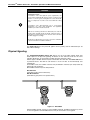
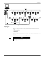
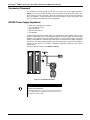
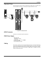
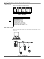
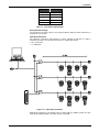
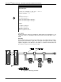
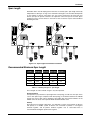
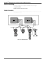
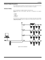
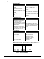
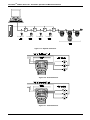
GENERAL FIRST IN FIELDBUS smar MAI / 99 GERAL INSTALLATION, OPERATION AND MAINTENANCE MANUAL TM FOUNDATION SERIES 302 OF FIELD DEVICES FP302 FY302 LD302 IF302 FI302 VERSÃO 3 TM TT302 FOUNDATION GE R A L - F F ME smar web: www.smar.com e-mail: [email protected] Specifications and information are subject to change without notice. BRAZIL Smar Equipamentos Ind. Ltda. Rua Dr. Antonio Furlan Jr., 1028 Sertãozinho - SP 14170-480 Tel.: +55 16 645-6455 Fax: +55 16 645-6450 e-mail: [email protected] ARGENTINA Smar Argentina Soldado de La Independencia, 1259 (1429) Capital Federal – Argentina Telefax: 00 (5411) 4776-1300 / 3131 e-mail: [email protected] CHINA Smar China Corp. 3 Baishiqiao Road, Suite 30233 Beijing 100873, P.R.C. Tel.: +86 10 6849-8643 Fax: +86-10-6894-0898 e-mail: [email protected] FRANCE Smar France S. A. R. L. 42, rue du Pavé des Gardes F-92370 Chaville Tel.: +33 1 41 15-0220 Fax: +33 1 41 15-0219 e-mail: [email protected] GERMANY Smar GmbH Rheingaustrasse 9 55545 Bad Kreuznach Germany Tel: + 49 671-794680 Fax: + 49 671-7946829 e-mail: [email protected] MEXICO Smar México Cerro de las Campanas #3 desp 119 Col. San Andrés Atenco Tlalnepantla Edo. Del Méx - C.P. 54040 Tel.: +53 78 46 00 al 02 Fax: +53 78 46 03 e-mail: [email protected] SINGAPORE Smar Singapore Pte. Ltd. 315 Outram Road #06-07, Tan Boon Liat Building Singapore 169074 Tel.: +65 6324-0182 Fax: +65 6324-0183 e-mail: [email protected] MIDDLE EAST Smar Middle East Al Sadaka Tower, Suite 204 P.O. Box 268 Abu Dhabi Tel: 9712-6763163 / 6760500 Fax: 9712-6762923 e-mail: [email protected] USA Smar International Corporation 6001 Stonington Street, Suite 100 Houston, TX 77040 Tel.: +1 713 849-2021 Fax: +1 713 849-2022 e-mail: [email protected] Smar Laboratories Corporation 10960 Millridge North, Suite 107 Houston, TX 77070 Tel.: +1 281 807-1501 Fax: +1 281 807-1506 e-mail: [email protected] Smar Research Corporation 4250 Veterans Memorial Hwy. Suite 156 Holbrook , NY 11741 Tel: +1-631-737-3111 Fax: +1-631-737-3892 e-mail: [email protected] Index Table of Contents INDEX OF FIGURES................................................................................................... IV INDEX OF TABLES .................................................................................................... IV INTRODUCTION .......................................................................................................... V INSTALLATION ........................................................................................................ 1.1 NETWORK WIRING .............................................................................................................................1.1 PHYSICAL SIGNALING........................................................................................................................1.2 TOPOLOGIES ......................................................................................................................................1.2 BUS TOPOLOGY .................................................................................................................................1.2 TREE TOPOLOGY ...............................................................................................................................1.2 DAISY CHAIN TOPOLOGY..................................................................................................................1.5 POINT-TO-POINT TOPOLOGY............................................................................................................1.6 FIELDBUS NETWORK COMPONENTS ..............................................................................................1.6 POWER SUPPLY .................................................................................................................................1.6 DEVICE QUANTITY .............................................................................................................................1.7 TERMINAL BLOCKS ............................................................................................................................1.7 TERMINATOR ......................................................................................................................................1.7 TERMINATOR PLACEMENT ...............................................................................................................1.8 PSI302 POWER SUPPLY IMPEDANCE ..............................................................................................1.8 REDUNDANT POWER.........................................................................................................................1.9 BT302 TERMINATOR...........................................................................................................................1.9 PS302 POWER SUPPLY .....................................................................................................................1.9 CABLING ..............................................................................................................................................1.9 CABLE OPTIONS ...............................................................................................................................1.10 TOTAL CABLE LENGHT ....................................................................................................................1.10 SPUR LENGHT ..................................................................................................................................1.13 RECOMMENDED MAXIMUM SPUR LENGHT .................................................................................1.13 INTERFACE AND BRIDGE ................................................................................................................1.14 BRIDGE CONNECTION .....................................................................................................................1.14 INTRINSIC SAFETY CONNECTION ..................................................................................................1.15 INTRINSIC SAFETY ...........................................................................................................................1.15 ATTACHING DEVICES TO THE FIELDBUS......................................................................................1.19 WIRING DOS AND DON’TS...............................................................................................................1.29 INTRINSIC SAFETY GALVANIC ISOLATOR.....................................................................................1.20 COMPUTER INSTALLATION.............................................................................................................1.21 INTERFACE CONNECTION ..............................................................................................................1.21 INTERFACE ADDRESING .................................................................................................................1.22 INTERFACE CONFIGURATION.........................................................................................................1.22 BASIC TROUBLESHOOTING ............................................................................................................1.23 OPERATION ............................................................................................................. 2.1 THE LCD DISPLAY .............................................................................................................................2.1 NORMAL DISPLAY OPERATION ........................................................................................................2.2 CONFIGURATION .................................................................................................... 3.1 FUNCTION BLOCKS............................................................................................................................3.1 DISPLAY TRANSDUCER BLOCK........................................................................................................3.1 LOCAL PROGRAMMING TREE...........................................................................................................3.3 DISPLAY CONFIGURATION USING SYSCON ...................................................................................3.3 PROGRAMMING USING LOCAL ADJUSTMENT ...............................................................................3.5 LOCAL ADJUSTMENT METHODOLOGY............................................................................................3.5 TRANSDUCER BLOCK........................................................................................................................3.7 HOW CONFIGURE A TRANDUCER BLOCK.......................................................................................3.7 CHANNEL.............................................................................................................................................3.8 CALIBRATION ......................................................................................................................................3.8 III TM Foundation Fieldbus Series 302 – Installation, Operation and Maintenance Manual MAINTENANCE PROCEDURES .............................................................................. 4.1 GENERAL.............................................................................................................................................4.1 RETURNING SMAR PRODUCTS AND/OR MATERIALS ....................................................................4.1 Index of Figures FIGURE 1.1 – HOUSING ROTATION.........................................................................................................1.1 FIGURE 1.2 – WIRING BLOCK ..................................................................................................................1.1 FIGURE 1.3 – WIRE MEDIA .......................................................................................................................1.2 FIGURE 1.4 – FIELDBUS NETWORK........................................................................................................1.3 FIGURE 1.5 – BUS TOPOLOGY ................................................................................................................1.4 FIGURE 1.6 – TREE TOPOLOGY ..............................................................................................................1.4 FIGURE 1.7 – DAISY – CHAIN TOPOLOGY..............................................................................................1.5 FIGURE 1.8 – DAISY – CHAIN WIRING ....................................................................................................1.5 FIGURE 1.9 – POINT-TO-POINT TOPOLOGY ..........................................................................................1.6 FIGURE 1.10 – TERMINAL BLOCKS .........................................................................................................1.7 FIGURE 1.11 – PSI302 CONNECTION ......................................................................................................1.8 FIGURE 1.12 – REDUNDANT POWER......................................................................................................1.9 FIGURE 1.13 – TOTAL CABLE LENGHT .................................................................................................1.10 FIGURE 1.14 – CABLE ENTITY PARAMETERS......................................................................................1.11 FIGURE 1.15 – GROUNDING THE SHIELD ............................................................................................1.12 FIGURE 1.16 – SPUR LENGHT AND TERMINATOR PLACEMENT .......................................................1.13 FIGURE 1.17 – BRIDGE CONNECTION ..................................................................................................1.14 FIGURE 1.18 – I. S. CONNECTION .........................................................................................................1.15 FIGURE 1.19 – REPEATER CONNECTION ............................................................................................1.18 FIGURE 1.20 – IF302 CONNECTION.......................................................................................................1.18 FIGURE 1.21 – FI302 CONNECTION.......................................................................................................1.18 FIGURE 1.22 – CONNECTION.................................................................................................................1.20 FIGURE 1.23 – IF302 IN I. S. INSTALLATION .........................................................................................1.20 FIGURE 1.24 – FI302 IN I. S. INSTALLATION .........................................................................................1.21 FIGURE 1.25 – INTERFACE CONNECTION ...........................................................................................1.21 FIGURE 1.26 – INTERFACE ADDRESSING ...........................................................................................1.22 FIGURE 2.1 – TYPICAL NORMAL DISPLAY SHOWING PV, IN THIS CASE 50.0%.................................2.2 FIGURE 2.2 – LCD DISPLAY .....................................................................................................................2.2 FIGURE 3.1 – FUNCTION AND TRANDUCERS BLOCKS ........................................................................3.2 FIGURE 3.2 – TRANSDUCER DISPLAY – CONFIGURATION..................................................................3.2 FIGURE 3.3 – THE SETINGS OF TRANDUCER DISPLAY PARAMETERS..............................................3.3 FIGURE 3.4 – THE SETINGS OF TRANDUCER DISPLAY PARAMETERS II...........................................3.4 FIGURE 3.5 – THE SETINGS OF TRANDUCER DISPLAY PARAMETERS II...........................................3.4 FIGURE 3.6 – THE SETINGS OF TRANDUCER DISPLAY PARAMETERS II...........................................3.5 FIGURE 3.7 – LOCAL ADJUSTMENT SWITCHES ....................................................................................3.5 FIGURE 3.8 – BROWSING GENERIC PARAMETER ................................................................................3.6 FIGURE 3.9 – ACTING A GENERIC VALUE..............................................................................................3.6 Index of Tables TABLE 1.1 – CABLE OPTIONS ................................................................................................................1.10 TABLE 1.2 – TOTAL CABLE LENGHT EXAMPLE ...................................................................................1.11 TABLE 1.3 – DEVICES PER SPUR VS. SPUR LENGHT.........................................................................1.13 TABLE 1.4 – TEMPERATURE CLASSIFICATIONS .................................................................................1.16 TABLE 2.1 – DISPLAY MESSAGES...........................................................................................................2.3 TABLE 3.1 – PARAMETER FUNCTION AND CLASS DEFAULT OF DEVICE ..........................................3.3 TABLE 3.2 – TRANSDUCER DISPLAY PARAMETERS ............................................................................3.4 TABLE 4.1 – DIAGNOSTIC OF THE FIELD DEVICES...............................................................................4.1 IV Introduction Introduction This manual introduces the series 302 of Fieldbus Foundation devices. They are: LD302 – FOUNDATION Fieldbus Pressure Transmitter, TT302 – FOUNDATION Fieldbus Temperature Transmitter, IF302 – FOUNDATION Fieldbus Triple Channel Current to Fieldbus Converter, FI302 – FOUNDATION Fieldbus Triple Channel Fieldbus to Current Converter, FP302 - FOUNDATION Fieldbus to Pressure Converter and FY302 FOUNDATION Fieldbus Positioner. They are based on a field-proven technology that provides reliable operation and high performance. The digital technology used in the Series 302 enables the choice of several types of function blocks. An easy interface between the field and the control room and several interesting features that considerably reduce the installation, operation and maintenance costs and will develop new ways to improve plant performance, plant safety and plant availability. Fieldbus is not only a replacement for 4-20 mA or intelligent device protocols, it contains much more. Fieldbus is a complete network system enabling migration and distribution of the control functions to field devices, and vastly expands the amount of process and non-process information flowing both from and to field devices. Some of the advantages of bi-directional digital communications are known from existing smart field devices protocols: Higher accuracy, multi-variable access, remote configuration and diagnostics, and multi-dropping of several devices on a single pair of wires. Those protocols were not intended to transfer control data, but maintain information. Therefore, they were slow, being not efficient enough to be used to digital control by communication and not giving opportunity to come to control strategies totally reside in the field. Fieldbus overcame these limitations. Closed loop control with performance like a 4-20 mA system requires higher speed. Since higher speed requires higher power consumption, this clashes with the need for intrinsic safety. Therefore a moderately high communication speed was selected, and the system was designed to have minimum communication over-head. Using scheduling, the system controls the variables poling, algorithm execution and the traffic to optimize the network usage, thus achieving high and secure closed loop performance. Using Foundation Fieldbus technology, with its capability to interconnect several devices, very large control schemes can be constructed. In order to be user friendly, the function blocks 1 concept was introduced , it means, basic automation functions performed by an application. Each function block processes input parameters according to a specified algorithm and an internal set of contained parameters. They produce output parameters that are available for use within the same device or by other one in the application process. Using them, the user may easily build and overview complex control strategies. Another advantage can be seen as extending flexibility, considering that the control strategy may be edited without having to rewire or change any hardware. Each field device has a set of blocks likes Analog Input, PID, Control Selector, etc., eliminating the need for a separate control devices. The communication requirement is considerably reduced, and that means less dead-time and tighter control is achieved, not to mention the 2. reduction in cost. Other function blocks are also available They allow flexibility in control strategy implementation and guarantee interoperability together of Device Description. The need for implementation of fieldbus in small as well as large systems was considered when developing the Series 302 of fieldbus devices. They have a common feature of being able to act as a master on the network and be configured locally using a magnetic tool, eliminating the need for a configurator or console in very basic applications. Get the best results of the Foundation Fieldbus Series 302 by carefully reading these instructions. 1 Users of SMAR CD600 multi-loop digital controller should be familiar with this, since it was implemented several years ago. 2 For more details, Please look at Function Blocks Instruction Manual V TM Foundation Fieldbus Series 302 – Installation, Operation and Maintenance Manual WARNING This Manual is compatible with version 3.XX, where 3 denote software version and XX software release. The indication 3.XX means that this manual is compatible with any release of Series 302 field devices with software version 3. VI Section 1 Installation Network Wiring Access the wiring block by removing the Electrical Connection Cover. This cover can be locked closed by the cover locking screw to release the cover, rotate the locking screw clockwise. (See Figure 1.1 - Housing Rotation). GEREM101.CDR Figure 1.1 - Housing Rotation Cable access to wiring connections is obtained by one of the two outlets. Conduit threads should be sealed by means of code-approved sealing methods. The unused outlet connection should be plugged accordingly. The wiring block has screws on which fork or ring-type terminals can be fastened. (See Figure 1.2 - Wiring Block). For convenience there are two ground terminals: one inside the cover and one external, located close to the conduit entries. Avoid routing signal wiring close to power cables or switching equipment. GEREM102.CDR Figure 1.2 - Wiring Block 1-1 TM Foundation Fieldbus Series 302 – Installation, Operation and Maintenance Manual WARNING HAZARDOUS AREAS In hazardous zones with explosion proof requirements, the covers must be tightened with at least 7 turns. In order to avoid moisture or corrosive gases, hand tighten the covers until the Orings are compressed. Lock the covers closed with the locking screw. In hazardous zones with intrinsically safe or non-incendive requirements, the circuit entity parameters and applicable installation procedures must be observed. Cable access to wiring connections is obtained by one of the two conduit outlets. Conduit threads should be sealed by means of code-approved sealing methods. The unused outlet connection should be plugged accordingly. Should other certifications be necessary, refer to the certification or specific standard for installation limitations. The Series 302 devices are protected against reverse polarity, and can withstand up to 35 VDC without damage. Physical Signaling The Foundation Fieldbus Series 302 devices use the 31.25 kbit/s voltage mode wire media option for the physical signaling. All devices on the same bus must use the same signaling. All devices are connected in parallel along the same pair of wires. Various types of fieldbus devices may be connected on the same bus. The Series 302 device is powered via bus. The limit for such devices is 16 for one bus for non-intrinsically safe requirements. In hazardous areas, the number of devices may be limited to 4 devices per safety barrier by intrinsically safe restrictions. One fieldbus network may have many barriers. Bus-Powered (Field device takes power from the bus) Non Bus-Powered (Field devices gets power over separate wires) GEREM103.CDR Figure 1.3 - Wire Media A Smar fieldbus System consists of several fieldbus networks. A fieldbus network may consist of several segments. Several fieldbus devices may be connected to each segment 1-2 Installation GEREM104.CDR Figure 1.4 - Fieldbus Network Topologies Almost any topology is possible. It is mainly a matter of where the terminator is connected. • Bus • Tree (Chicken-foot) • Daisy-chain • Point-to-point As far as fieldbus is concerned that are all alike, what matters is the placement of the terminator. Of course combinations of two or more topologies is possible. NOTE Ring topology is not possible. Because connecting the bus in a ring damage the Termination scheme. 1-3 TM Foundation Fieldbus Series 302 – Installation, Operation and Maintenance Manual Bus Topology Devices are distributed along the trunk connected through spurs. A spur may be up to 120 m long. GEREM105.CDR Figure 1.5 - Bus Topology Tree topology A main trunk runs from the control room into the field where it branches out to the individual devices. For tree topology it is important to ensure that the spur length does not exceeds the maximum allowed. GEREM106.CDR Figure 1.6 - Tree Topology 1-4 Installation Daisy Chain Topology Cable is chained from device to device. It is important to ensure that a device may be disconnected without other devices also being disconnected. Therefore make sure to use same conduit for ”in” and “out” wires in order to enable removal of device without interrupting bus. GEREM107.CDR Figure 1.7 - Daisy-Chain Topology GEREM108.CDR Figure 1.8 - Daisy-Chain Wiring 1-5 TM Foundation Fieldbus Series 302 – Installation, Operation and Maintenance Manual Point-to-Point Topology Only two devices connected to each other. This topology does not take advantage of the multidrop capability of fieldbus. Typically used only on workbench with device and notebook computer. GEREM109.CDR Figure 1.9 - Point-to-Point Topology Fieldbus Network Components • • • • • • • • • • • • • Cable (“Media”) Field devices Transmitters Valve positioners Converters Programmable controllers Interfaces Operator stations Hand-held terminals Terminator Power supply impedance and power supply Intrinsic safety barriers / Galvanic Isolators Bus analyzer Power Supply The power consumption varies from one device to another. There are no upper or lower limits. The power consumption is indicated on device. The lower consumption a device has the better, especially in intrinsic safety applications. It is important that the wire resistance is not too high making the supply voltage at the device too low. Good connections and junctions must be made to keep resistance low. It is possible to test the voltage (not signal) on the installed network using a hand-held Digital voltmeter (DVM). Power Supply Example • • • • • • • 1-6 PSI302 output voltage is 16 V (worst case) Cable resistance for 1.9 km is 84 ohm Device needs minimum 9 V Maximum voltage drop is 7 V Maximum total current draw is 83 mA Each device needs 15 mA Maximum 5 devices, or shorter cable Installation Device Quantity Rules of thumb: 32 separately powered or 12 bus-powered plus an interface. 4 per safety barrier in hazardous area (one fieldbus network may have many barriers). More or less devices may be possible depending on wire size and length, power consumption and barrier rating. Using repeaters more devices are theoretically possible (224), though there is a penalty on control cycle time and display update. Terminal Blocks No special terminal blocks are required and no special couplers are required to join spurs to trunk. Keep it inside a junction box. GEREM110.CDR Figure 1.10 - Terminal Blocks Terminator The terminator has two major functions: • Signal current shunt: The communication signal is transmitted as a current but received as a voltage, the terminator does the conversion. • Prevent signal reflection: The communication signal bounces back when it reaches the end of the wire, potentially distorting itself. The terminator prevents that. There are actually two terminators in a fieldbus network, one in each end. However, one of them is typically built into the power supply impedance or safety barrier. Terminator - shunt The low-speed wire media fieldbus signal is transmitted as an AC current with amplitude of 1020 mA. Each of the two terminators has impedance of 100 ohm, and since they are connected in parallel the network will have resulting impedance of 50 ohm. The terminator will cause a voltage drop as the transmitted current passes through. A voltage with amplitude of 250-500 mV will therefore be seen over the network. The receivers in all the other fieldbus devices sense this voltage. Terminator - end When the fieldbus signal traveling down the wire reaches the end, it is faced with a change in impedance from the characteristic impedance of the wire to the infinite impedance of open air. This will cause a part of the signal power to be reflected back up through the wire. The reflected signal interferes with the oncoming "real" signal. If the reflected signal is powerful enough, it may distort the "real" signal such that the communication does not work. The terminator has the same impedance as the cable such that when placed at the end the fieldbus signal sees no change in impedance and hence there is no reflection. It is also clear that the terminator must be at the end of the wire to really work. 1-7 TM Foundation Fieldbus Series 302 – Installation, Operation and Maintenance Manual Terminator Placement The terminator should be placed at each end of the trunk. The power supply impedance PSI302 has one of the terminators built in. In bus topology the end of the trunk is easy to see. In tree topology the end of the trunk is where the spurs branch out. There may never be more than two terminators, and the terminators must not be forgotten. The bus may function with only one terminator, but performance may be degraded. PSI302 Power Supply Impedance • • • • • Allows use of standard power supplies. 18 +/-2 V, 300 mA output. Built-in terminator DIN-rail or panel mount Fail indication A power supply impedance module shall be connected between the fieldbus and the power supply. Prevents short circuit of communication signal by the power supply. The power supply impedance also regulates the power supply voltage. If a normal power supply is connected directly to the fieldbus the communication will be short-circuited, the power supply impedance prevents this. The power supply impedance has built functionality for automatic and bumpless switch over from a main to a backup in redundant configuration should the main unit not provide power Connect maximum 4 channels per PSI302 per PS302. GEREM111.CDR Figure 1.11 - PSI302 Connection NOTE AC Short Circuit Prevention A DC power supply acts as a short on a AC circuit. Therefore the power supply impedance is introduced. The impedance acts as a 3kΩ impedance between field 1-8 Installation Redundant Power Automatic bumpless switchover between redundant power supplies. Only one PSI302 should have the terminator connected, or a separate power supply-end terminator is used. GEREM112.CDR Figure 1.12 - Redundant Power BT302 Terminator Intrinsically safe, equivalent unprotected capacitance. PS302 Power Supply • Wide input range: 90-264 VAC (47-440 Hz) 127-367 VDC • 24 VDC, 1.5 A output; up to four PSI302. • Galvanically isolated • Failure indication and output Cabling Several types of cable may be used, though shielded twisted pair is recommended. Depending on the size and other factors of the cable the maximum length can vary varies. Four cable types have been identified, though there are many more options. No special cable is required. Normal instrument wires may be used. However, "fieldbus cable" is available from several vendors to make selection easier. 1-9 TM Foundation Fieldbus Series 302 – Installation, Operation and Maintenance Manual Cable Options Type A is recommended for best possible performance. Pair Shield Twist Size Max Length Type Single Y Y 0.75 mm2 1900 m A Multi Y Y 0.32 mm2 1200 m B Multi N Y 0.13 mm2 400 m C Multi Y N 1.25 mm2 200 m D Table 1.1 - Cable Options For non-twisted cable the distance is very short even for thick and shielded wire. NOTE Detail characteristics for type “A” Zo @ 31.25 kHz = 100 ohm +/- 20 % Max attenuation @ 39 kHz = 3 dB/km Max capacitive unbalance to shield = 2 nF/km Max DC resistance per conductor = 22 ohm/km Max propagation delay change 7.8-39 kHz = 1.7 us/km Conductor cross-sectional area = 0.75 mm2 Total Cable Length Maximum total cable length depends on the cable used. The total length includes the trunk and all spurs. GEREM113.CDR Figure 1.13 - Total Cable Length 1-10 Installation Segment Length Trunk 240 m Spur 1 80 m Spur 2 120 m Spur 3 40 m Total 480 m Table 1.2 - Total Cable Length Example Entity Parameter Example It is good practice to make a table for each segment (barrier) listing the entity parameters for each part for easy analysis Cable Entity Parameters Pay attention to capacitance and inductance of cables. Typically the L/R ratio of a cable is used rather than just L since R cancels the effect of L. Typical cable values: • L/R = 25 uH/ohm • C = 200 nF/km GEREM114.CDR Figure 1.14 - Cable Entity Parameters Normally the capacitance is the limiting factor for cable length in a fieldbus network. A 1.9-km cable would contribute 380 nF, more than a barrier can handle. 1-11 TM Foundation Fieldbus Series 302 – Installation, Operation and Maintenance Manual NOTE Mixing Cable Types To check if a combination of cable types is within the specification the below equation may be used: L1/L1max + L2/L2max + … < 1 Where: L1 is length of cable type 1 L2 is length of cable type 2 L1max is the maximum length for cable type 1 L2max is the maximum length for cable type 2 Example: L1 = 1000 m of cable type A L2 = 100 m of cable type B 1000/1900 + 100/1200 = 0.61 Which is acceptable since 0.61 < 1 Cable Shield Shield is preferred to achieve best performance. Shield should cover minimum 90% of the cable length. If there is no shielding the cable should be within a metal conduit, which act as a shield. Grounding Only the shield should be grounded never the fieldbus wires. The shield should be grounded in only one point. The shield of the spurs shall be connected to the shield of the trunk. In high EMI/RFI environments several additional RF grounds of the shield may be done using capacitors, though this is rare. Do not use the shield as a conductor. The shield should be grounded at the negative terminal of the power supply. GEREM115.CDR Figure 1.15 - Grounding the Shield 1-12 Installation Spur Length Remember that in tree like topologies the branches are actually spurs. Spur length is basically independent of cable type as long as the maximum total length is not exceeded, but depends on the number of devices connected to the spur. There should never be more than four devices per spur. No special connectors are required to connect the spur to the trunk. Spurs should be used to connect devices to the trunk so that one device may be removed without disturbing the other. GEREM116.CDR Figure 1.16 - Spur Length and Terminator Placement Recommended Maximum Spur Length Total 1 per spur 2 per spur 3 per spur 4 per spur 25-32 1m 1m 1m 1m 19-24 30 m 1m 1m 1m 15-18 60 m 30 m 1m 1m 13-14 90 m 60 m 30 m 1m 1-12 120 m 90 m 60 m 30 m Table 1.3 - Devices per spur vs. spur length These lengths are rules of thumb. Longer is very often possible. Spur Precautions It is important to pay attention to spur length when star topology is used since the spurs in this case is often quite long in comparison with bus topology. If the distance between the PSI302 and the PCI is more than 120 m (maximum spur length) then the internal terminator in the PSI302 cannot be used, and a separate BT302 should instead be used. Polarity Some devices have polarity, others don't. It is important to ensure correct polarity for devices with polarity. In a fieldbus system all devices are connected in parallel, i.e. all negative terminals together, and all positive terminals together. Use of color-coded wires is recommended to distinguish positive from negative. 1-13 TM Foundation Fieldbus Series 302 – Installation, Operation and Maintenance Manual Interface and Bridge An interface is used to connect a computer to the fieldbus. There are two types: • Permanent installation • Temporary connection A bridge is used to pass data between networks. Bridge Connection Data may be passed between devices on different channels on the same PCI card, or even between different PCI cards. GEREM117.CDR Figure 1.17 - Bridge Connection 1-14 Installation Intrinsic Safety Connection Several SB302 may be connected to each channel such that 16 or more devices per safe area channel is possible while there are only 4 device per hazardous area segment. Intrinsic Safety Special considerations for fieldbus installations in hazardous areas. All the normal intrinsic safety limitations apply. Refer to requirements from regulatory agencies. • • • • • Voltage Current Power Capacitance Inductance This in turn means a limited amount of devices and a limited cable length. Special fieldbus safety barriers or galvanic isolators are required. Any conventional barrier or barrier for other networks cannot be used. GEREM118.CDR Figure 1.18 - I.S. Connection 1-15 TM Foundation Fieldbus Series 302 – Installation, Operation and Maintenance Manual Area Classifications IEC & CENELEC FM & CSA Zone 0: Explosive gas-air mixture continuously present, or present for long periods. Zone 1: Explosive gas-air mixture is likely to occur in normal operation Zone 2: Explosive gas-air mixture not likely to occur and, if it occurs, it will exist only for a short time. Division 1: Hazardous concentrations of flammable gases or vapors - or combustible dusts in suspension - continuously, intermittently or periodically present under normal operating conditions. Division 2: Volatile flammable liquids or flammable gases present but normally confined within closed containers or systems from which they can escape only under abnormal operating or fault conditions. Combustible dusts not normally in suspension nor likely to be thrown into suspension I.S. Equipment categories IEC & CENELEC FM & CSA Ex ia: Explosion protection maintained with up to two component or other faults. I. S. apparatus may be connected in, and associated apparatus may be connected into Zone 0, 1 and 2 hazardous areas (Germany requires galvanic isolation and a system certificate for Zone 0). Ex ib: Explosion protection maintained with up to one component or other fault. I. S. apparatus may be located in, and associated apparatus maybe connected into Zone 1 and 2 hazardous areas. Only one category: Safety maintained with up to two component or other faults. I. S. apparatus may be located in, and associated apparatus may be connected into Division 1 and 2 hazardous locations. Gas Classifications IEC & CENELEC FM & CSA Surface industries Group IIC: acetylene Group IIC: hydrogen Group IIB: ethylene Group IIA: propane Surface industries Class I, Group A: acetylene Class I, Group B: hydrogen Class I, Group C: ethylene Class I, Group D: propane Class II, Group E: metal dust Class II, Group F: carbon dust Class II, Group G: flour, starch, grain Class III: fibers and flying Mining industry Unclassified: methane (firedamp) Mining industry Group I: methane (firedamp) Temperature Classifications Maximum temperature produced under fault conditions at an ambient temperature of 40 °C. TEMPERATURE MAXIMUM T1 450 ºC T2D 215 ºC T4 135 ºC T2 300 ºC T3 200 ºC T4A 120 ºC T2A 280 ºC T3A 180 ºC T5 100 ºC T2B 260 ºC T3B 165 ºC T6 85 ºC T2C 230 ºC T3C 160 ºC Table 1.4 - Temperature Classifications 1-16 Installation Barrier Entity Parameters “o” Maximum external capacitance (Co), the permitted total capacitance on hazardous area side of barrier Maximum external inductance (Lo), the permitted total inductance on hazardous area side of barrier Maximum output voltage (Uo), the open circuit output voltage from hazardous area side of barrier Maximum output current (Io), the short circuit output current from hazardous area side of barrier Maximum output power (Po), the power output from hazardous area side of barrier. Field Device Entity Parameters “i” Maximum input current (Ii), the current that may be applied to device. Maximum input power (Pi), the power that may be applied to device. Maximum input voltage (Ui), the voltage that may be applied to device. Maximum internal capacitance (Ci), the residual capacitance with which the device loads the network. Maximum internal inductance (Li), the residual inductance with which the device loads the network Intrinsic Safety Requirements • Lowest Ui >= Uo • Lowest Ii >= Io • Lowest Pi >= Po • Sum Ci + Ccable <= Co • Sum Li + Lcable <= Lo • L/Rcable <= L/Rbarrier SB302 Fieldbus Galvanic Isolator • Typically four hazardous area devices per barrier. • Works as repeater (special model) • Built-in terminator • Entity parameters Uo = 22.5 V Io = 206 mA Po = 1.15 W Co = 154 nF Lo = 300 nH L/R = 30.7 uH/ohm • Current Capacity: 60 mA Repeater Connection The SB302 safety barrier may also function as a repeater. Using a repeater may increase cable length or number of devices. Up to four repeaters may be connected onto one fieldbus, thereby linking five fieldbus segments. Cable lengths of up to 9500 may therefore be achieved. 1-17 TM Foundation Fieldbus Series 302 – Installation, Operation and Maintenance Manual GEREM119.CDR Figure 1.19 - Repeater Connection GEREM120.CDR Figure 1.20 - IF302 Connection GEREM121.CDR Figure 1.21 - FI302 Connection 1-18 Installation Attaching Devices to the fieldbus Fieldbus devices may be attached to and removed from an operating fieldbus. When removing a device ensure that fieldbus wires are not short-circuited or come in contact with other wires, shield or ground. Fieldbus devices with different communication speeds cannot be mixed on the same network. Bus-powered and non bus-powered devices may be mixed and matched on the same network. Do not connect non-fieldbus devices to the network. Analogue type indicators with a coil etc. may adversely affect communication. High impedance DVMs may be used for troubleshooting etc. Attachment Procedure When the device is received, unpack it and connect it stand-alone or into your fieldbus network to a computer with SYSCON, e.g. a configurator station. • Assign the tag to the device using the SYSCON. The "Assig Tag" menu can be found at device and bridge devices menu. • Bring the device into the field and connect it to the fieldbus operating network if you assigned the device stand-alone. • Download the configuration to the device or the whole network. NOTE The assign tag operation can be done in a device attached to an operating fieldbus network with several devices. You can change the tag of a fieldbus device on an operating network without disconnecting it if the new tag does not exist yet. WARNING When you are assigning a new device's tag, you are modifying your system configuration. It can cause a lot of trouble in terms of the control scheme, as function blocks and links configuration. The whole configuration of your system should be revised. Network Devices Addresses 0-15 - reserved Addresses 16-247 - may be used for the field instruments. Addresses 248-251 - “default” addresses used for devices, which have not had their proper address, assigned yet. Address 252-255 -“visitor” addresses used by temporarily connected devices like configurators. Wiring DOs and Don’ts Normal wiring procedures apply: • No loose connections • No exposed conductors • Water proof junction boxes • Signal wires not too close to power wires • No safety barriers in parallel 1-19 TM Foundation Fieldbus Series 302 – Installation, Operation and Maintenance Manual Intrinsic Safety Galvanic Isolator May be used instead of safety barrier. A special fieldbus isolator with repeater is required. Does not require safety earth like a barrier. Functions as a repeater allowing several hazardous areas segment to be connected to the safe area segment of a network. GEREM122.CDR Figure 1.22 - Connection GEREM123.CDR Figure 1.23 - IF302 in I. S. Installation 1-20 Installation GEREM124.CDR Figure 1.24 - FI302 in I. S. Installation Computer Installation PCI Internal fieldbus Interface • Four fieldbus channels • Up to eight per station • Galvanically isolated • Plugs into ISA slot • Up to four redundant cards/stations in parallel • Non-volatile memory • Runs independently from computer. Interface Connection Up to four redundant operators on the same fieldbus network. Computer must be off when cards are inserted or removed. GEREM125.CDR Figure 1.25 - Interface Connection 1-21 TM Foundation Fieldbus Series 302 – Installation, Operation and Maintenance Manual Interface Addressing The PCI card has a network address like all devices. No two devices on the network must have the same address. This of course applies to PCI too. GEREM126.CDR Figure 1.26 - Interface Addressing Interface Configuration See the PCI - Process Control Interface - User's Manual. 1-22 Installation Basic Troubleshooting Communication errors are automatically detected and indicated in operator console and engineering tools. As for all troubleshooting, removing parts one-by-one until it works finding the fault through elimination, is a useful way. It is also a good idea to test a problem device on its own on the workbench. Make sure: • • • • Correct polarity Correct tag and address Integrity of the fieldbus network Supply voltage is sufficient, min 9.5 V even during communication. If there is no communication at all, there is a problem with its configuration or installation. NOTE Advanced Troubleshooting To find serious problems the FBVIEW bus analyzer application program may be used to study the communication messages in order to find the problem. An oscilloscope (balanced/isolated - e.g. battery operator) may also be a useful tool in extreme cases. Communication Errors Installation problems, not configuration or others mainly cause communication errors. • Poor connections • Wrong or no terminator placement • Too low or unstable power supply • Too long or over-populated spurs • Wrong or no grounding • Water filling due to poor plugs and cable-glands 1-23 TM Foundation 1-24 Fieldbus Series 302 – Installation, Operation and Maintenance Manual Section 2 Operation The Series 302 device has an optional digital LCD display that works as a local operator interface. It can be used for some basic configuration and operation. However, all configuration, operation and diagnostics may also be done remotely using for example a configurator or operator console. (See SYSCON 3.0 User's Manual). Configuration is basically assignment of tags and building of the control strategy by selecting blocks, linking them and adjusting the contained parameters so as to obtain the desired operation. The local and remote operator interfaces also provide monitoring and actuation of variables, such as process variables and Setpoint. These variables have been grouped depending on usage and may be accessed in a single communication. When alarms and other critical events occur, the function block automatically notifies the user by communication, thus the operator interface does not have to perform periodic polling to determine if there is an alarm condition. A specified period of time is spent for an acknowledgment to be received. This occurs even if the condition that caused the alert to be detected no longer exists. If the acknowledgment is not received within a pre-specified timeout period, the event notification will be retransmitted. The communication also automatically informs about configuration changes to static data. An event is generated by internal mechanism when a change occurs, so the Host does not have to make continuous checks. Scheduled and unscheduled traffic represents the network I/O of the function block application. Through scheduled communication, the transfer of parameters may be synchronized with function block execution so that function blocks which use this data receive it before they are scheduled to execute. Consequently, the closed loop control performance as for an analog system can be achieved. Thanks to the mechanisms for passing of configuration and alarm this so-called nonoperational traffic has been reduced to a minimum, leaving more time for operational traffic and again improving control performance. After configuration, the system resolves tags and parameter names into a specific format, which optimizes communication. Using the device internal function blocks, the speed can be improved even more. For instances, by using the internal PID block for control one communication less is required as compared to if the controller was in another device. This reduces the control application period of execution. The LCD Display The integral indicator is able to display each parameter belongs to function blocks, which are user-selectable. Some of them can be changed by local action, according to user configuration and properties of these parameters. When a variables is chosen by the user, the display shows it indicating the parameter name defined, the value and its status when its exists. The different fields and status indicators are explained in Figure 2.1 - Typical Normal Display Showing PV, in this case 50.0 %. 2-1 TM Foundation Fieldbus Series 302 – Installation, Operation and Maintenance Manual Normal Display Operation During normal operation, the Series 302 device stays in the normal display mode. In this mode, it shows a variable indicated by user configuration. (See Figure 2.1 - Typical Normal Display Showing PV, in this case 50.0 %). Whenever the displayed value exceeds "19999, it will be displayed with a two-digit mantissa and an exponent. Magnetic Tool Span Hole Zero Hole GEREM201.CDR Figure 2.1 - Typical Normal Display Showing PV, in this case 50.0 % The display indicates values and parameters simultaneously with most status indicators. The normal display is interrupted when the user performs action by the local adjustment. The display is also capable of displaying error and other messages. (See Table 2.1 - Display Messages). GEREM202.CDR Figure 2.2 - LCD Display 2-2 Operation DISPLAY INIT BOUT DESCRIPTION The device is in initializing mode after power on. The sensor is open or not connected properly. (When it is applicable). FAIL The device presents some fail or malfunctioning FACT The device is recovering default configuration to non-volatile memory. Table 2.1 - Display Messages 2-3 TM Foundation 2-4 Fieldbus Series 302 – Installation, Operation and Maintenance Manual Section 3 Configuration The way to configure the communication and function block for the Series 302 devices is using a system configuration device, commonly called Host. The heaviest and most difficult task is automated and the risk of a configuration mistake is reduced. In this system, the addressing of a device is first done using the physical device tag of that device. Before a new and non-initialized device is connected to the network it must be configured with this tag. The name of its operation is Assign Physical Device Tag. 1. Connect a configurator to the non-initialized Series 302 device alone on the line. Assign the physical device tag to the Series 302 device. 2. The Series 302 device is now initialized and can be connected to the others devices into the network. 3. The configurator will automatically assign a station address to the Series 302 device recently hooked into the network bringing it to initialized mode. 4. The Series 302 device is brought to the operational state and its ready to be configured as part of the control strategy. See how to configure the physical device tag and how to configure On-line and Off-line the Series 302 device in the SYSCON 3.0 - User's Manual. NOTE The local adjustment can be used for some operations and configuration tasks. This eliminates the need of a powerful system configurator, but requires more knowledge of the fieldbus communication mechanism. This may be a money saving solution for small systems, but it is very time consuming and susceptible to configuration errors in a large system. See in the Local Adjustment Methodology section how to use the local adjustment. Function Blocks See Function Blocks Instruction's Manual. Display Transducer Block The Series 302 device can be equipped with one LCD. In the normal monitoring mode (not executing actions by the local adjustment), the display can show one variable. The Display Transducer Block can be configured by SYSCON. In the example below, the LD302 has four blocks instantiated (created as block per user): The Analog Input block, the Display and Transducer blocks and Resource. 3-1 TM Foundation Fieldbus Series 302 – Installation, Operation and Maintenance Manual The device was instantiated as LD302 As you can see the Transducer and Display are treated as special type of Function Blocks, called Transducer Blocks. Here, you can see all blocks instantiated. GEREM301.CDR Figure 3.1 - Function and Transducers Blocks A group of parameters should be set in order to show and/or act on certain parameter by local adjustment interface. This specify a Tag by what the parameter is recognized. The relative index of the parameter selected. This mnemonic appears on the LDC Display. Monitoring or Acting on its parameter GEREM302.CDR Figure 3.2 - Transducer Display - Configuration 3-2 Configuration The transducer display is treated as a common function block. It means, its block can be configured by SYSCON setting parameters by choosing values according to customer's needs. The LCD display can be used for monitoring or acting purpose, a parameter present on the fieldbus network or inside a function block can be shown at LCD or be acted as for example: Calibration and Tuning parameters. Local Programming Tree The programming tree is a one-level-shaped menu system, allowing configuration of the most important items. The menu itself can be configured like a transducer block by SYSCON or other configurator in order to select and optimize the access to functions. Each field device leaves the factory with a default configuration. There are different defaults configuration for each type of field device, but normally its includes Tag and Output transducer block as parameter for monitoring parameters for calibration purpose as you can see in the table below. PARAMETER FUNCTION CLASS TAG MONITORING READ TRANSDUCER OUTPUT MONITORING READ LOWER CALIBRATION READWRITE UPPER CALIBRATION READWRITE Table 3.1 - Parameter Function and Class Default of Device Display Configuration using SYSCON The selection of display parameters should be seen as function block configuration. The user should determine and configure for each parameter selected the settings described in the table below. This default values indicates that a parameter index 14 and sub-index 2 of the Transducer Block - LD302 is configured as Monitoring. The parameter will appear as P_VAL on the LCD display. The index 14 means: the Output of transducer block. It is a variable called type DS64, it means, status + float value. The sub index sets the member associated to the record parameter, For exemplo: The 1 selects the status and 2 selects the value. When a parameter is a float point this sub index number does not cause any effect on the LCD display. GEREM303.CDR Figure 3.3 - The Settings of Transducer Display parameters 3-3 TM Foundation Fieldbus Series 302 – Installation, Operation and Maintenance Manual BLOCK TAG RELATIVE INDEX Tag assigned to the Function Blocks Relative Index of the parameter in the object dictionary SUB INDEX The logical sub-address of the member MNEMONIC Mnemonic name representing each parameter FLOAT INC_DEC Step for Incrementing or decrementing in float or integer format DECIMAL POINT Number of decimal places after mantissa ACCESS ALPHA_NUM REFRESH Read or/and Write permission Select mnemonic or value in alphanumeric display when the value is higher than 10,000 Flag assigned to indicate new configuration Table 3.2 - Transducer Display Parameters These settings are necessary to configure one parameter to be shown on LCD display. GEREM304.CDR Figure 3.4 - The Settings of Transducer Display parameters II After the download operation at first time, the display block will set all the block tag parameters with default values. GEREM305.CDR Figure 3.5 - The Settings of Transducer Display parameters II 3-4 Configuration Each time when you modify the settings of Display Block you should update your settings choosing Update Display. The operation of configurating the Display can be done On_Line or Off_line by SYSCON GEREM306.CDR Figure 3.6 - The Settings of Transducer Display parameters II parameters II Programming Using Local Adjustment The device must be fitted with the digital display for this function to be enabled. The device has two holes for magnetic switches activated by the magnetic tool located under the identification Plate. See Figure 3.7 - Local Adjustment Switches. Magnetic Tool Span Hole Zero Hole GEREM307.CDR Figure 3.7 - Local Adjustment Switches This magnetic tool enables adjustment and monitoring of the most important parameters of the blocks. The jumper labeled “Loc. Adj.” on top of the main circuit board must be in place to on position, for this function to be enabled and the device must be fitted with the digital display for access to the local adjustment. Local Adjustment Methodology Enter the local adjustment by inserting the magnetic tool in the ZERO hole. Entry has been gained into the one level menu. Leaving the tool in the ZERO hole, browse through the items in the menu. The ZERO hole is used for browsing. By moving the tool to the SPAN hole , the parameter can be set to other value. 3-5 TM Foundation Fieldbus Series 302 – Installation, Operation and Maintenance Manual NOTE SUMMARY: Zero (z) Browses Span (s) Selects / Enters. To browse the available options for parameters, move the tool to the ZERO hole to go to the specific menu option. See Figure 3.7 - Local Adjustment Switches. Then make a selection by moving the tool to SPAN when the choice is displayed. If the options are on/off, or enumeration, the option will appear in the value field. The mnemonic of each parameter will be displayed at alphanumeric field. This is for viewing only, changes are not to be made to the tag configured for the block. If the tag is longer than five characters, it will circulate to the left. Magnetic Tool Span Hole Zero Hole GEREM308.CDR Figure 3.8 - Browsing a generic parameter For parameters that are values, enter the adjustment menu by moving the tool to the SPAN hole the value will be incremented, once with a _ symbol indicating that, by moving the tool to the SPAN hole, the value will be decreased. Incrementing and decreasing at first will be slow, then increasing in speed. By temporarily removing the tool from the SPAN hole and then reinserting it, the actuation speed is reduced. Magnetic Tool Span Hole Zero Hole GEREM309.CDR Figure 3.9 - Acting on a generic value Unless otherwise specified, the numerical field indicates the value of the actuated variable. Remove the tool when the desired value is reached. When browsing through options, and miss the item desired, just leave the tool in ZERO and wait for the option to reappear. 3-6 Configuration When incrementing a variable, and go beyond the value desired, move the tool to ZERO and wait until the decrement option of the same variable appears. By moving the tool to SPAN, reduce it to the desired value. For "undershoot" the opposite applies. To exit from any menu, remove the tool from any hole and for time-out that an escape sequence will return back to normal display. After selection, inserting the tool in SPAN when configuring a parameter with options, the menus will automatically go to the option branch be entered. If the tool is kept from the ZERO and SPAN hole for a few seconds, the display will return to normal. This may also be used as a way to intentionally return to normal display without having to wait to the escape time-out. Most of what is entered with the local adjustment is stored in a nonvolatile EEPROM to be saved in case of power failure. When parameters with options are selected, these are automatically stored in this EEPROM. After the power failure, the stored value will be used. The Local Adjustment interface was defined to be an easy Human-machine interface. One position always moves on menus and the other acts on parameters changing their values or status. The local adjustment can be totally configured by SYSCON. The user can define the parameters to be adjusted or monitored locally. Usually those parameters are output and input from control function blocks. Also, it is possible to change mode and set tuning parameters. By inserting the magnetic tool in the ZERO hole the user can navigate on the menu and by inserting the tool in the Span hole the actions can be done. Scrolls the display items until the variable selected is located. Under its option, just remove the magnetic tool. The last occurrence of action under the magnetic tool will be displayed on the display. The options above are example of some possibilities. Almost any of the Function block parameters can be configured by SYSCON to be adjusted locally. The user should select them from the following classes: • • • • • Integer Float Status + Float Mode Tag (read-only) All of them can be set or monitored by using the magnetic tool. The default values for the local adjustment are trim parameters, transducer output or input and Tag identifying the block and when necessary parameters to identify the borne or sensor number. Transducer Block Transducer block insulates function block from the specific I/O hardware, such as sensors, actuators. Transducer block controls access to I/O through manufacturer specific implementation. This permits the transducer block to execute as frequently as necessary to obtain good data from sensors without burdening the function blocks that use the data. It also insulates the function block from the manufacturer specific characteristics of certain hardware. By accessing the hardware, the transducer block can get data from I/O or passing control data to it. The connection between Transducer block and Function block is called channel. These blocks can exchange data from its interface. Normally, transducer blocks perform functions, such as linearization, characterization, temperature compensation, control and exchange data to hardware. How to Configure a Transducer Block Each time when you select a field device on SYSCON by instantiating on the Operation menu, automatically you instantiate one transducer block and it appears on screen. The icon indicates that one transducer block has been created and by clicking twice on the icon, you can access it. 3-7 TM Foundation Fieldbus Series 302 – Installation, Operation and Maintenance Manual The transducer block has an algorithm, a set of contained parameters and a channel connecting it to a function block. The algorithm describes the behavior of the transducer as a data transfer function between the I/O hardware and other function block. The set of contained parameters, it means, you are not able to link them to other blocks and publish the link via communication, defines the user interface to the transducer block. They can be divided into Standard and Manufacturer Specific. The standard parameters will be present for such class of device, as pressure, temperature, actuator, etc., whatever is the manufacturer. Oppositely, the manufacturers specific ones are defined only for its manufacturer. As common manufacturer specific parameters, we have calibration settings, material information, linearization curve, etc. When you perform a standard routine as a calibration, you are conducted step by step by a method. The method is generally defined as guide line to help the user to make common tasks. The SYSCON identifies each method associated to the parameters and enables the interface to it. Channels The channel number which references a channel value which is sent via internal, manufacturer-specific to function block. It starts at 1 until the number of variables available per each transducer. Calibration It is a specific method to make the calibration operation. It is necessary to match the source of reference applied to or connected to the device with the wished value. At least four parameters should be used to configure this process: CAL_POINT_HI, CAL_POINT_LO, CAL_MIN_SPAN, and CAL_UNIT. Those parameters define the highest and lowest calibrated values for this device, the minimum allowable span value for calibration (if necessary) and the engineering unit selected for calibration purposes, when its is different by SENSOR_RANGE or FINAL_VALUE_RANGE. 3-8 Section 4 Maintenance Procedures General SMAR Series 302 devices are extensively tested and inspected before delivery to the end user. Nevertheless, during their design and development, consideration was given to the possibility of repairs being made by the end user, if necessary. In general, it is recommended that end users do not try to repair printed circuit boards. Spare circuit boards may be ordered from SMAR whenever necessary. Refer to the item "Returning Materials" at the end of this Section. Since the transducer block is intimately attached to the I/O hardware, it has access to a lot of information about hardware status, sensor connections, control circuit by feedback action, Non-volatile memory burned, Automatic Zero Failed, etc. Another status from Transducer block configuration as Excess Correction, Under Span Minimum Allowed, Applied Process Out of Range, Calibration Failed, etc., can be received after certain operations TROUBLESHOOTING SYMPTOM PROBABLE SOURCE OF PROBLEM Device Connections _ Check wiring polarity and continuity. _ _ Check for shorts or ground loops. Check if the power supply connector is connected to main board. _ Check if the shield is not used as a conductor. It should be grounded at only one end. Power Supply _ Check power supply output. The voltage must be between 9 - 32 VDC at the Series 302 device terminals. Noise and ripple should be within the following limits: Network Connection NO COMMUNICATION _ Check that the topology is correct and all devices are connected in parallel. _ _ Check that two bus terminators are OK and correctly positioned. Check that the bus terminators are according to the specifications. _ Check length of trunk and spurs. _ Check spacing between couplers. Network Configuration _ Make sure the Device Tag is configured if system configuration is desired. _ Make sure that device address, master connection, and the address. Electronic Circuit Failure _ Check the main board for defect by replacing it with a spare one. Table 4.1 - Diagnostic of the Field Devices Returning SMAR Products and/or Materials Should it become necessary to return the transmitter to SMAR, simply contact our nearest office (see addresses list included in this manual), informing the defective instrument's product model and serial number. SMAR will provide you with the necessary instructions to return products to our factory. In order to speed up analysis and solution of the problem, the defective item should be returned with a description of the failure observed, with as much details as possible. Other information concerning to the instrument operation, such as service and process conditions, is also helpful. 4-1 TM Foundation 4-2 Fieldbus Series 302 – Installation, Operation and Maintenance Manual