1
GOM-802 DC MILLI-OHM METER
USER MANUAL
Declaration of Conformity
We
GOOD WILL INSTRUMENT CO., LTD.
No. 95-11, Pao-Chung Rd., Hsin-Tien City, Taipei Hsien, Taiwan
GOOD WILL INSTRUMENT (SUZHOU) CO., LTD.
No.69 Lushan Road, Suzhou New District Jiangsu, China.
declare that the below mentioned product
GOM-802
is herewith confirmed to comply with the requirements set out in the Council Directive on
the Approximation of the Law of Member States relating to Electromagnetic Compatibility
(89/336/EEC, 92/31/EEC, 93/68/EEC) and Low Voltage Equipment Directive
(73/23/EEC).
For the evaluation regarding the Electromagnetic Compatibility and Low Voltage
Equipment Directive, the following standards were applied:
◎ EMC
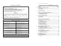
CONTENTS
PAGE
1. PRODUCT INTRODUCTION...............................................…… 1
1-1. Description………………………………………………………….. 1
1-2. Key Feature……………………………………………..………….. 2
2.
SPECIFICATIONS………………...…………………………… 4
3.
PRECAUTIONS BEFORE OPERATION…….………….…...
4.
◎ Safety
Low Voltage Equipment Directive 73/23/EEC & amended by 93/68/EEC
IEC / EN 61010-1: 2001
PANEL INTRODUCTION……………………..………….…...
8
4-1. Front Panel……………………………………………………….… 10
4-2. Rear Panel……………………………………….………………….. 10
5.
EN 61326-1: Electrical equipment for measurement, control and laboratory use –– EMC
requirements (1997+A1: 1998)
Conducted and Radiated Emission
Electrostatic Discharge
EN 55011: 1998 class B
IEC 61000-4-2: 1995+A1: 1998
Current Harmonic
Radiated Immunity
IEC 61000-3-2: 2000
IEC 61000-4-3: 1996+A1: 1998
Voltage Fluctuation
Electrical Fast Transients
IEC 61000-3-3: 1995
IEC 61000-4-4: 1995
Surge Immunity
------------------------IEC 61000-4-5: 1995
Conducted Susceptibility
------------------------IEC 61000-4-6: 1996
Power Frequency Magnetic Field
------------------------IEC 61000-4-8: 1993
Voltage Dips/ Interrupts
------------------------IEC 61000-4-11: 1994
7
3-1. Unpacking the Instrument...…………….………….…………….... 7
3-2. Checking the Line Voltage………………..………………………... 7
OPERATION INTRODUCTION...……………………...…….. 11
5-1. The [SHIFT] key and function keys………………..….…………...
5-2. Warm up…………………..………………………………………..
5-3. Over-range indicator…..……………………………………………
5-4. TRIG standby indication…………………………………………...
5-5. Input overload protection.….…………………………..…………..
5-6. Interface Operation…….…………………………………………..
5-7. Installation and Operation………………………………………….
6.
MEASUREMENT INSTRUCTION…………………………… 13
6-1. Resistance measurement……………………………………………
6-2. Temperature measurement………………………………………...
6-3. Temperature Compensation Measurement………………………..
6-4. General Function……………………………………………………
7.
11
11
11
11
11
12
12
13
17
18
19
MEASUREMENT TECHNIQUES…………….……………… 26
7-1. 4-wire measurement……………………………………………….. 26
7-2. Temperature measurement………………………………………... 28
8.
MAINTENANCE………………………………………….……. 31
8-1. Line fuse replacement……………………………….……………... 31
8-2. Line voltage conversion…..…………………………..……………. 31
8-3. Cleaning…………………………………………………………….. 32
⎯
i ⎯
GOM-802 DC MILLI-OHM METER
GOM-802 DC MILLI-OHM METER
USER MANUAL
USER MANUAL
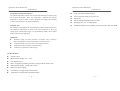
SAFETY TERMS AND SYMBOLS
FOR UNITED KINGDOM ONLY
These terms may appear in this manual or on the product:
NOTE: This lead/appliance must only be wired by competent persons
WARNING. Warning statements identify condition or
practices that could result in injury or loss of life.
WARNING: THIS APPLIANCE MUST BE EARTHED
IMPORTANT: The wires in this lead are colored in accordance with
CAUTION. Caution statements identify conditions or
practices that could result in damage to this product or
other property.
WARNING: This equipment is not for measurements
performed for CAT II, III and IV.
The following symbols may appear in this manual or on the product:
the following code:
Green/ Yellow:
Blue:
Brown:
Earth
Neutral
Live (Phase)
As the colors of the wires in main leads may not correspond with the
colors marking identified in your plug/appliance, proceed as follows:
The wire which is colored Green & Yellow must be connected to the
Earth terminal marked with the letter E or by the earth symbol
or colored Green or Green & Yellow.
The wire which is colored Blue must be connected to the terminal
which is marked with the letter N or colored Blue or Black.
DANGER
ATTENTION
Protective
High Voltage refer to Manual Conductor
Terminal
Earth(ground)
Terminal
The wire which is colored Brown must be connected to the terminal
marked with the letter L or P or colored Brown or Red.
If in doubt, consult the instructions provided with the equipment or
contact the supplier.
⎯ ii ⎯
⎯ iii ⎯
GOM-802 DC MILLI-OHM METER
GOM-802 DC MILLI-OHM METER
USER MANUAL
This cable/appliance should be protected by a suitably rated and
approved HBC mains fuse: refer to the rating information on the
equipment and/or user instructions for details. As a guide, cable of
0.75mm2 should be protected by a 3A or 5A fuse. Larger conductors
would normally require 13A types, depending on the connection
method used.
Any mounded mains connector that requires removal /replacement
must be destroyed by removal of any fuse & fuse carrier and disposed
of immediately, as a plug with bared wires is hazardous if a engaged
in live socket. Any re-wiring must be carried out in accordance with
the information detailed on this label.
USER MANUAL
1. PRODUCT INTRODUCTION
1-1. Description
GOM-802 is a high precision programmable DC Milli-ohm meter suitable
for the low resistance measurements of switches, relays, connectors, PCB
tracks and variety of other devices. With the easy-to-use features, superior
performance, and automatic test interfaces described as below, GOM-802 is
obviously a reliable and handy instrument for the low resistance
measurements.
Easy-to-use features:
Utilizing the arrow key for setting the percentage of upper and lower limit based on
the normal value can make it easier to execute the HI-LO-GO comparator function.
Besides, through the Alarm Buzzer setting can indicate the PASS/FAIL status, and
all kinds of output status can be indicated through Handler Interface output.
The RELATIVE feature that enables GOM-802 to remove the stray resistance easily,
and the 20 sets of Normal/Hi/Lo setting memories can satisfy with different kind of
test condition. Also, the last setting will be recalled every time when the GOM-802
is turned on.
Superior Performance:
There are nine measurement ranges from 30mΩ to 3MΩ selected automatically or
manually with the constant current between 1μA and 1A, 0.05% high accuracy,
1μΩ resolution and four terminals Kelvin connection to make a reliable and
consistent test result.
The flexible choice for a high measurement accuracy at speed of 7 sampling/sec
(full scale at 30000) or a less measurement accuracy at speed of 30 sampling/sec
(full scale at 3000) can match with the speed requirement of test.
⎯ iv ⎯
⎯ 1 ⎯
GOM-802 DC MILLI-OHM METER
GOM-802 DC MILLI-OHM METER
USER MANUAL
USER MANUAL
Temperature Compensation (Option):
z
Four-wire measurement method.
The optional temperature probe PT-100 can control the measuring resistance to meet
z
Auto-recall last setting on re-power on.
the required temperature. When the temperature coefficient and required
z
Diode test.
z
Alarm setting for PASS/FAIL test result.
z
Sampling rate: 7 or 30 sampling/sec.
z
Standard interface: Scan, Handler, optional interface: RS-232 GPIB.
temperature is keyed in under TC mode, GOM-802 will display the measuring
resistance corresponding to the required temperature.
Automatic Test:
For automatic system applications, the GOM-802 provides a handler interface that
can indicate the output status on PASS, FAIL, HI, LO, READY, or EOT, and
control signal of measurement trigger. An optional RS-232 GPIB is also available
for the computer control application.
Application:
z
Production testing for contact resistance of switches, relays, connectors,
cables and printed circuit boards and other low resistance devices.
z
Component testing of resistors, motors, fuses, heating elements.
z
Incoming inspection and quality assurance testing.
z
Conductivity evaluation for product design.
1-2. Key Feature:
z
z
30,000 counts.
Measurement Range: 30mΩ~3MΩ.
z
0.05 high accuracy.
z
Hi/Lo comparator and limit percentage setting with 20 memory sets.
z
Measurement of REL, Actual and % value.
z
Manual or Auto-ranging.
z
Continuous or Trigger measurement mode.
z
Temperature compensation and measurement.
⎯ 2 ⎯
⎯ 3 ⎯
GOM-802 DC MILLI-OHM METER
GOM-802 DC MILLI-OHM METER
USER MANUAL
USER MANUAL
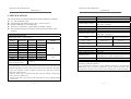
2. SPECIFICATIONS
The specifications are operated under the essential conditions as follows:
z A 1-year calibration cycle.
z An operating temperature of 18 to 28℃ (64.4 to 82.4℉).
z Relative humidity not exceeding 80%.
z Accuracy is expressed as ±(percentage of reading + digits).
z The instrument requires 30 minutes warm-up time to achieve rated
accuracy.
1. Resistance Measurement
30000 counts (speed : 7 times/second)
Range
Resolution
30m
300m
3
30
300
3k
30k
300k
3Meg
1μ
10μ
100μ
1m
10m
100m
1
10
100
Measuring
Current
1A approx.
100mA
100mA
10mA
1mA
100μA
100μA
10μA
1μA
Accuracy
0.1%+6*
0.05%+6*
0.05%+3
0.05%+2
0.05%+2
0.05%+2
0.05%+2
0.05%+2
0.05%+2
Open-terminal
Voltage
3V
4.8V
3000 counts Accuracy
±5 counts **
(speed: 30 times/second)
*When the instrument is set to 30mΩ or 300mΩ range, the resistance value will
be changed while connecting or disconnecting the test lead to the panel due to the
different temperature between internal and external of the instrument. Therefore,
it must wait 1 minute in order to obtain an accurate value after the test lead is
connected or disconnected.
* When use Kelvin clip to resume testing after long time ending, it needs more
time to wait for a stable value.
** In high speed mode, first assure that the instrument has been grounded through
power cord.
⎯ 4 ⎯
Measurement
Auto-ranging
Over input range
Four-terminal method.
Provided.
“OL” indication
30m~3Ω range: 30VpDC
Maximum Applied voltage
Other range: 100VpDC
Comparator
20 sets of comparator status can be selected.
Buzzer mode switchable
NON, PASS, FAIL
2.Temperature Measurement
Platinum resistor.
Temperature sensor (option)
Lead length: 1.5m approx.
Accuracy
Accuracy
Range
Speed: 7 times/second
Speed: 30 times/second
-9.9℃ ~ 39.9℃
0.3%+0.5℃
0.3%+2℃
-50.0℃ ~ -10.0℃
0.3%+1.0℃
0.3%+3℃
40℃ ~ 100℃
3. Temperature Correction Function
Temperature correction range 0.0℃~40.0℃
Reference temperature range 0℃~99.9℃
Thermal coefficient range
±9999 ppm
Accuracy of temperature compensation for
Temperature range
3930 ppm/Cu wire, speed: 7 times/second.*
0℃~39.9℃
0.3%+resistance measurement accuracy.
40℃~100℃
0.6%+resistance measurement accuracy.
* The temperature coefficiency for the other setting must be calculated individually
according to different conditions.
* If the temperature coefficiency or the difference between the environmental
temperature and the require temperature exceeds normal operation, after
compensation calculation, the variation of the reading value will be tremendous.
⎯ 5 ⎯
GOM-802 DC MILLI-OHM METER
GOM-802 DC MILLI-OHM METER
USER MANUAL
3. PRECAUTIONS BEFORE OPERATION
4. Interface
Handler interface
Scanner
RS-232 GPIB (option)
5. ENVIRONMENTAL
Operation
Environment
Storage temperature
6. GENERAL
Power source
Accessories
Dimension
Weigh
USER MANUAL
Signal: START TTL input
Signal: LOW, HIGH, FAIL, PASS, EOT, READY
total 6 TTL outputs.
(This function is valid only under the resistance
measurement mode and the compare mode is
enabled.)
Signal: READY, PASS, LOW, HIGH, CLOCK,
STRB total 6 TTL outputs.
(This function is valid only under the resistance
measurement mode and the compare mode is
enabled.)
IEEE488.1-1987, IEEE488.2-1992 and SCPI-1994
Indoor use, altitude up to 2000m.
Ambient Temperature 0℃ to 40℃.
Relative Humidity 80% (Maximum).
Installation category II
Pollution Degree
2
-10℃ to 70℃.
3-1.Unpacking the Instrument
The product has been fully inspected and tested before shipping from the factory.
Upon receiving the instrument, please unpack and inspect it to check if there is
any damage caused during transportation. If any sign of damage is found, notify
the bearer and/or the dealer immediately.
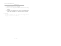
3-2.Checking the Line Voltage
The product can be applied by any kind of line voltages shown in the table below.
Before connecting the power plug to an AC line outlet, make sure the voltage
selector of the rear panel is set to the correct position corresponding to the line
voltage. It might be damaged the instrument by connecting to the wrong AC line
voltage.
WARNING. To avoid electrical shock the power cord protective
grounding conductor must be connected to ground.
AVERISS: Pour éviter les chocs électriques, le fil de terre du
AC 100V/120V/220V/230V±10%, 50/60Hz, 27VA,
22W.
Test Lead × 1, Instruction manual × 1,
Programmable manual × 1 (option),
Temperature sensor (option) × 1
251(W)×91(H)×291(D) m/m
Approx. 3 kg
WARNING : To avoid electrical shock, the power cord
cordon secteur doit impérativement être relié à la terre.
When line voltages are changed, replace the required fuses shown as below:
Line
Model
Range
Fuse
voltage
GOM-802
100V
120V
Line
voltage
90-110V TT0.3A
108-132V 250V
220V
230V
Range
Fuse
198-242V T0.25A
216-250V 250V
protective grounding conductor must be connected to ground.
CAUTION:To avoid damaging the instrument, do not use it
in a place where ambient temperature exceeds 40℃.
⎯ 6 ⎯
WARNING. To avoid personal injury, disconnect the power cord
before removing the fuse holder.
⎯ 7 ⎯
GOM-802 DC MILLI-OHM METER
GOM-802 DC MILLI-OHM METER
USER MANUAL
USER MANUAL
4. PANEL INTRODUCTION
Figure 4-2. Rear Panel
Figure 4-1. Front Panel
⎯ 8 ⎯
⎯ 9 ⎯
GOM-802 DC MILLI-OHM METER
GOM-802 DC MILLI-OHM METER
USER MANUAL
USER MANUAL
5. OPERATION INTRODUCTION
4-1. Front Panel
1. Interface Indicator
2. Normal value displayed area.
3. Comparator indicator.
4. Upper limit percentage display area.
5. Low limit percentage display area.
6. Measurement value displayed area.
7. Functions control indicator.
8. Measurement terminal: Sense HI, Sense LO
9. Current source terminal: Source HI, Source LO.
10. The negative measurement terminal has the same potential as the
circuit earth terminal, but can not be replaced by it.
11. Function Control knob.
WARNING: This equipment is not for measurements
performed for CAT II, III and IV.
4-2. Rear Panel
12. GPIB Interface terminal.
13. RS232 Interface terminal.
14. Handler and SCAN interface terminal.
15. Temperature compensation probe terminal (TC SENSOR).
16. Line voltage selector and input fuse holder.
17. AC Power-line connector.
5-1. The [SHIFT] key and function keys
The [SHIFT] button is used to enable the secondary function of certain
function keys that with blue symbols printed above. The SHIFT LED will
be on after pressed the [SHIFT] button. At this time, only the buttons with
blue symbols are workable. To release SHIFT function, press [SHIFT]
again.
5-2. Warm up
The instrument requires half-an-hour warm up to achieve rated accuracy.
5-3. Over-range indication
If the input exceeds the full scale of the selected range, the instrument will
indicate over-range input by lighting the “OL” message on the display.
5-4. TRIG standby indication
Under the TRIG mode, change the range or power on the instrument, the
“————” message will be displayed on the measurement displayed area,
now the instrument is in the TRIG standby status. The decimal is
represented the range. When proceeding the TRIG measurement, the
measurement displayed area will display the present measuring value.
5-5. Input overload protection
The maximum allowable input is shown as table 5-1. Please proceed the
measurement accordingly.
Table 5-1:
RANGE
30mΩ, 300mΩ,3Ω
Other ranges
MAXIMUN INPUT
30Vp DC
100Vp DC
WARNING: To avoid shock hazard and/or instrument
damage, do not apply input potentials that exceed the input
overload limits shown in table 5-1.
⎯ 10 ⎯
⎯ 11 ⎯
GOM-802 DC MILLI-OHM METER
GOM-802 DC MILLI-OHM METER
USER MANUAL
5-6. Interface Operation
This instrument equips RS-232 as standard device with a D-SUB 9 PIN
SHELL on the rear panel. Besides, the instrument also provides a GPIB
option device with a 24 PIN SHELL in blue. The configuration is
compliance with IEE488.
For further detailed operation, please refer to the Interface manual.
5-7. Installation and Operation
Operate the GOM-802 in a location with a suitable environment free from
dust, direct exposition of sunlight, and strong effect of magnetic fields.
If you have no idea about the resistor value before testing, start from the
high resistor value range to the low until the right value can be read out.
USER MANUAL
6. MEASUREMENT INSTRUCTION
6-1. Resistance measurement
(1) Resistance measurement function
1) Get into resistance measurement function by pressing [SHIFT] and
[TEMP] in sequence to select main function mode.
2) Press [▲]or[▼] can switch over the function, and 3 kinds of
measurements “ohm”, “℃” and “TC” will be displayed on the panel.
3) Press “ohm” and [ENTER] to get into resistance measurement
mode.
4) Use [▲]or[▼] to switch to adequate range or press [AUT/MAN] for
Auto range measurement.
(2) Compare function
Compare function:
1) Enable or disable the Compare function by pressing [COMP]
button.
2) Make HI, GO, LO judgment shown on the panel indicator according
to the setting of the upper and low normal value percentage.
3) When the Compare function is relieved, the setting for % and REL
will be relieved too.
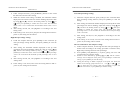
Example:
Normal value: 100.00
up limit: 10.0% = up limit value: 110.00
down limit: 20.0% = down limit value: 80.00
The indicators of GO, HI, and LO will be lighted up according to
the resistance value of DUT:
109.00
GO indicator lights up
120.00
HI indicator lights up
70.00
LO indicator lights up
Normal value setting:
⎯ 12 ⎯
⎯ 13 ⎯
GOM-802 DC MILLI-OHM METER
GOM-802 DC MILLI-OHM METER
USER MANUAL
1) Under Compare function, press [NORMAL] button to turn on/off
the function of normal value setting.
2)
USER MANUAL
Low limit percentage setting:
When the normal value setting is enabled, the maximum number
displayed on the normal value area will be flashing, adjust the value
by using [▲]and [▼], and move the flashing number by using [ ] or
1) Under the compare function, press [LOW] to turn on/off the down
limit percentage setting function, and press [SHIFT] to clear the
setting.
[
], then press [ENTER] to confirm the correct value. The maximum
normal value is set at 33000 while the minimum normal value is set at
00000.
2) After setting, the maximum number displayed on the up/down limit
percentage area will be flashing, adjust the value by using [▲]and
3) After setting, the HI, LO, GO judgment is according to the new
setting value.
4) If the setting is not saved, once jump out the setting function and repower on, the setting will be cleared.
High limit percentage setting:
1) Under the compare function, press [HIGH] to turn on/off the up
limit percentage setting function, and press [SHIFT] to clear the
setting.
2) After setting, the maximum number displayed on the up limit
percentage area will be flashing, adjust the value by using [▲]and
[▼], and move the flashing number by using [
] or [
], then press
[ENTER] to confirm the correct value. The maximum up limit percentage
value is set at 999 while the minimum up limit percentage value is set at
000.
3) After setting, the HI, LO, GO judgment is according to the new
setting value.
4) If the setting is not saved, once leave the setting function and repower on, the setting will be cleared.
⎯ 14 ⎯
[▼], and move the flashing number by using [
] or [
], then press
[ENTER] to confirm the correct value. The maximum down limit
percentage value is set at 999 while the minimum down limit percentage
value is set at 000.
3) After setting, the HI, LO, GO judgment is according to the new
setting value.
4) If the setting is not saved, once leave the setting function and repower on, the setting will be cleared.
The save function for the compare setting:
1)
2)
3)
4)
Under Compare function, set the high and low limit percentage of
normal value according to the setting procedure of Normal value,
High limit percentage and low limit percentage.
Press [SHIFT] and [RECALL] in sequence getting into save and
recall function of Compare setting.
Switch to save function by pressing [▲] or [▼], and the “SAVE”
message will be displayed on the panel, press [ENTER] to confirm the
setting, or press [SHIFT] to clear the setting.
Among the message “S MXX” displayed on the panel, XX means the
number of the storage group from 00 to 19. Use [▲] or [▼], [
] or
[
] to adjust the save location, then press [ENTER] to replace the
previous save location, or press [SHIFT] to clear the setting.
⎯ 15 ⎯
GOM-802 DC MILLI-OHM METER
GOM-802 DC MILLI-OHM METER
USER MANUAL
The recall function for the compare setting:
1) Under Compare function, set the high and low limit percentage of
normal value according to the setting procedure of Normal value,
High limit percentage and low limit percentage.
2) Press [SHIFT] and [RECALL] in sequence getting into save and
recall function of Compare setting.
3) Switch to recall function by pressing [▲] or [▼], and the “CALL”
4)
message will be displayed on the panel, press [ENTER] to confirm the
setting, or press [SHIFT] to clear the setting.
Among the message “C MXX” displayed on the panel, XX means the
number of the recall group from 00 to 19. Use [▲] or [▼], [
] or [
]
to adjust the recall location, the panel will display the normal value and
the up/down limit percentage of normal value.
5)
After recall setting, the HI, LO, GO judgment is according to the
new setting value.
The Buzzer function setting:
1) Under the Compare mode, press [SHIFT] and [
] in sequence
getting into buzzer setting. The panel will display the present
setting status, the message “NON” means no action, “bP” means the
buzzer is activated when the test is pass, and “bF” means the buzzer
is activated when the test is failed.
2) Use [▲] or [▼] to select “NON”, “bP” or “bF”, then [ENTER] to confirm
the setting, or press [SHIFT] to clear the setting.
The buzzer will be disabled once leave the Compare mode.
3)
Display measurement value percentage:
1) Under the Compare mode, press [SHIFT] and [%/VALUE] in
sequence to select resistance value which is based on actual value or
normal value to calculate the percentage, and displays it on the
panel.
Normal value: 20.000
Actual value:
10.000
Percentage:
050.00%
⎯ 16 ⎯
USER MANUAL
2)
Enable the measurement value percentage calculation, and the auto
range function will be annulled.
(3) REL FUNCTION
1) Use this function to do zero adjustment when the test lead or the
resistance of the DUT needs to be adjusted.
2) Pre-set a reference value, then every value must minus the reference
value before displaying on the panel for the compare judgment.
3) Under the compare mode, enable REL function, the auto-range
function will be annulled.
4) After calculation, if the value is negative, the minus symbol and the
number will be displayed alternately on the position of MSD (most
significant digit) under low converted speed mode (7 times/second),
while only the minus symbol will be displayed on the position of
MSD under high converted speed mode.
6-2. Temperature measurement
(1) Temperature measurement
1) Connect an optional temperature probe to the rear panel.
2) Press [SHIFT] and [TEMP] in sequence getting into main function
selection mode.
3) Press [▲] or [▼] can switch over 3 kinds of functions of “ohm”, “℃”, and
“TC” on the panel.
4) Select “ ℃ ”and
press [ENTER] getting
into
temperature
measurement mode. The measuring value will be displayed on the
normal value displayed area.
⎯ 17 ⎯
GOM-802 DC MILLI-OHM METER
GOM-802 DC MILLI-OHM METER
USER MANUAL
(2) REL function
(3) REL function
Pre-set a reference value, then every value must minus the reference
value before displaying on the panel for the compare judgment.
Pre-set a reference value, then every value must minus the reference
value before displaying on the panel for the compare judgment.
6-4. General Function
(3) Single range
There is only a single range for the temperature measurement.
6-3. Temperature Compensation Measurement
(1) Temperature compensation measurement mode
1) The adequate resistance value of the DUT can be calculated through
the environment temperature, the setting coefficient of temperature
of the DUT, and the require observation temperature.
2) Press [SHIFT] and [TEMP] in sequence getting into main function
selection mode.
3) Press [▲] or [▼] can switch over 3 kinds of functions of “ohm”, “℃”, and
“TC” on the panel.
4) Select “TC” and press [ENTER] getting into temperature compensation
measurement mode.
5) The up limit percentage area display the observation temperature and the
setting coefficient of temperature will be displayed on the normal value
displayed area.
6) Use [▲] or [▼], [
USER MANUAL
] or [
] to set the require observation temperature
(1) Converted speed selection
1) Press [SHIFT] and [SPEED] in sequence to switch over the
converted speed.
2) Low converted speed: 7 times/second, full scales: 30000.
3) High converted speed: 30 times/second, full scale: 3000.
4) The converted speed function can be applied on the measurement of
resistance, temperature, and temperature compensation.
(2) Auto range function
1) Press [AUTO/MAN] to switch over auto range or manual range.
2) Under the Compare mode, switch over the range will annulled the
previous setting of % or REL function.
3) The temperature measurement only has a single range.
4) Under external trigger mode, Auto range function is disabled.
(3) Trigger function
1) Press [MANUAL TRIG] getting into external trigger mode.
2) Each time when the [MANUAL TRIG] button is pressed, the EXT
LED will be flashing once and the panel value will be updated again.
Press [SHIFT] and [INT] in sequence to leave Trig mode.
and the coefficient of temperature, then press [ENTER] to confirm the
setting or press [SHIFT] to clear the setting.
(2) Range selection
Use [▲] or [▼] to switch over the range or set [AUTO/MAN] to auto range
mode.
⎯ 18 ⎯
⎯ 19 ⎯
GOM-802 DC MILLI-OHM METER
GOM-802 DC MILLI-OHM METER
USER MANUAL
3)
USER MANUAL
Under the TRIG mode, change the range or power on the instrument, the
FAIL:
Output “1” to GND, means the judgment of the compare
function is High or low.
PASS:
Output “1” to GND, means the judgment of the compare
function is GO.
“————” message will be displayed on the measurement displayed area,
now the instrument is in the TRIG standby status. The decimal is
represented the range. When proceeding the TRIG measurement, the
measurement-displayed area will display the present measuring value.
The output current from all output collector and +5V
terminal can not exceed 60mA.
(4) Handler interface
The handler interface provides a TTL input (START), 6 TTL outputs,
including LOW, HIGH, FAIL, PASS, EOT and READY (This function is
valid only under the resistance measurement mode and the compare mode is
(5) Interface setting
Please refer to the programmable manual.
(6) SCAN interface
enabled).
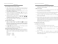
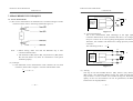
9-PIN D-SHELL (FEMALE)
1) The scan interface provides 6 TTL outputs, including READY,
PASS, LOW, HIGH, FAIL, CLOCK, and STRB.
START
GND
+5V
PASS
FAIL
READY
EOT
LOW
HIGH
9-PIN D-SHELL (FEMALE)
RELAY
PASS
STRB
CLOCK
START: Start trigger and proceed one time measurement, negative edge
trigger.
GND
+5V
LOW
HIGH
READY: Output “1” to GND, means the measurement is completed and
can proceed next trigger.
RELAY: Control the relay signal, and series signal output.
PASS:
Indicate PASS signal, and series signal output.
EOT:
Output “1” to GND, means the AD convert procedure is
completed, can change the DUT.
LOW:
Indicate LOW signal, and series signal output.
HIGH:
Indicate HIGH signal, and series signal output.
LOW:
Output “1” to GND, means the judgment of the compare
function is low.
HIGH: Output “1” to GND, means the judgment of the compare
function is high.
⎯ 20 ⎯
CLOCK: When every group of output signal (including READY,
PASS, LOW, HIGH) is ready, a CLOCK signal will be sent
out. There are 100 groups of output signals totally.
STRB: After all 100 groups of output signals have been ready, a
STRB signal will be sent out.
⎯ 21 ⎯
GOM-802 DC MILLI-OHM METER
GOM-802 DC MILLI-OHM METER
USER MANUAL
USER MANUAL
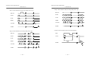
2) SCAN Operation
{ Set to SCAN mode from the resistance measurement mode, first
enable the compare function and change the range manually, then
press [SHIFT] and [SCAN] in sequence.
Step 1. After the SCAN setting, the message of “READY” will be
displayed on the panel, SCAN interface starts output:
RELAY:
], the
PASS:
maximum count can be up to number 100. Press [ENTER] to confirm
LOW:
| Set sweep count by adjusting [▲] or [▼], [
] or [
the setting or press [SHIFT] to cancel the setting.
HIGH:
} Set one count sweep delay time up to 30000 unit maximum or 30 unit
minimum (unit: 16.2ms) by adjusting [▲] or [▼], [
] or [
], then
CLOCK:
1
2
3
4
∬
∬
99
100
press [ENTER] to confirm the setting or press [SHIFT] to cancel the
STRB:
setting.
~ When the setting is completed, the message of “READY” will be
displayed on the measurement value displayed area. Now the setting of
Step 2. Press [MANUAL TRIG] to start scan:
range and up/down limit of the compare function can not be changed.
Proceed sweep function by press [MANUAL TRIG], and the result will
RELAY:
∬
∬
PASS:
∬
∬
LOW:
∬
∬
HIGH:
∬
∬
∬
∬
∬
∬
be output through SCAN interface.
Press [SHIFT] and [SCAN] in sequence to leave SCAN mode.
After sweep, the measurement results can be observed by
adjusting [▲] or [▼].
Please refer to the procedure of SCAN interface output as follows:
CLOCK:
1
2
STRB:
⎯ 22 ⎯
⎯ 23 ⎯
99
100
GOM-802 DC MILLI-OHM METER
GOM-802 DC MILLI-OHM METER
USER MANUAL
USER MANUAL
Step 5: Scan channel 100, the sweep delay time is up:
Step 3: Scan channel one, the sweep delay time is up:
RELAY:
∬
∬
RELAY:
∬
∬
PASS:
∬
∬
PASS:
∬
∬
LOW:
∬
∬
LOW:
∬
∬
HIGH:
∬
∬
HIGH:
∬
∬
CLOCK:
∬
∬
CLOCK:
∬
∬
∬
∬
1
2
STRB:
100
1
2
3
4
∬
STRB:
∬
RELAY:
∬
∬
∬
Data:
∬
PASS:
∬
∬
∬
Clock:
∬
LOW:
∬
∬
∬
HIGH:
∬
∬
∬
CLOCK:
∬
∬
∬
∬
∬
∬
∬
∬
2
3
STRB
⎯ 24 ⎯
n
n+1
100
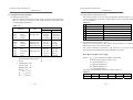
The account of output time for SCAN interface:
Step 4: Scan channel n, the sweep delay time is up:
1
99
20μs
32μs
128μs
∬
STRB:
100
20μs
⎯ 25 ⎯
GOM-802 DC MILLI-OHM METER
GOM-802 DC MILLI-OHM METER
USER MANUAL
USER MANUAL
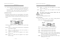
7. MEASUREMENT TECHNIQUES
r1
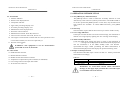
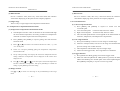
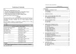
7-1. 4-wire measurement
I
(1) The 4-wire measurement can eliminate wire resistance and get accurate
resistance. Please refer to the wiring method as Figure 7-1.
CONSTANT
CURRENT
SOURCE
+
VOLTMETER
_
V
R
r2
Ohm Meter
Figure 7-1
Figure 7-2
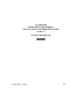
2) 4-wire measurement.
The 4-wire measurement takes advantage of the high input
resistance characteristic of the voltmeter that there is no voltagedrop on r3 and r4 as no current getting through these resistances.
Therefore, the voltmeter can measure the voltage precisely on the
resistance.
The measuring result is: R = V
I
r1
Note:
1. Before testing, make sure that the KELVIN clip is well
connected with the DUT.
2. The terminals of HF (Source HI), LF (Source LO), HS (Sense
HI) and LS (Sense LO) must be connected to front panel
terminals properly.
r3
CONSTANT
CURRENT
SOURCE
I
+
R V
_
VOLTMETER
r4
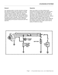
(2) Principle
1) The traditional 2-wire measurement result combines the test lead
resistance. Please refer to Figure 7-2 for the measurement result:
V
= r1 + R + r 2
I
⎯ 26 ⎯
Ohm Meter
r2
Figure 7-3
(3) Zeroing
The clip of test lead includes Source+ (HF), Source- (LF), Sense+
(HS), Sense- (LS) terminals. Before zeroing test, make sure that the
clip of Sense+ is next to Sense- for accurate zeroing test. When the
quality of the wire and material can not be guaranteed, use REL
function for zeroing adjustment.
⎯ 27 ⎯
GOM-802 DC MILLI-OHM METER
GOM-802 DC MILLI-OHM METER
USER MANUAL
USER MANUAL
7-2. Temperature measurement
(1) Reference temperature
The international Temperature Scale (ITS) is based on the following
table 7-1 which was revised in 1990 with seventeen fixed points and
corresponding temperatures.
Table 7-1:
Element
Type
(H2)
Hydrogen
(Ne)
Neon
Tripple point
(O2)
Oxygen
(Ar)
Argon
(Hg)
Mercury
Tripple point
(H2O)
Water
Tripple point
(Ga)
Gallium
Melting point
(In)
Indium
Freezing point
(Sn)
Tin
(Zn)
Zinc
(Al)
Aluminum Freezing point
(Ag)
Silver
(Au)
Gold
Note: 1. Temperature unit:
Thermodynamic temperature: T
Kelvin:
K
2. Temperature scale:
Celsius scale: ℃
Rankinescale: °R
Kelvin: ℉
℃ =5/9 (℉-32)
K = ℃+273.15
°R = ℉+459.67
⎯ 28 ⎯
Temperature
K
℃
13.8033
-259.3467
24.5561
-248.5939
54.3584
-218.7916
83.8058
-189.3442
234.325
-38.8344
273.16
+0.01
302.9146 29.7646
429.7485 156.5985
505.078
231.928
692.677
419.527
933.473
660.323
1234.93
961.78
1337.33
1064.18
(2) Temperature measurement sensor
The common usage for the resistance temperature detectors, RTD, is to
convert temperature into electro signal. Please refer to following table
7-2 of its feature:
Table 7-2
Feature
Description
1. Accuracy
Higher accuracy
2. Resolution
0.1~1.0℃ higher resolution
3. Speed of response
Slower
4. Self-heating
yes
5. Long term stability
Good
6. Output characteristic
Approx. 0.4 ohm/℃, near linear.
(3) Optional Platinum resistance sensor
This kind of temperature probe meets the specification of German
DIN43760: 1968, 3-wire measurement.
The relation between temperature and resistance can refer to the
description of the Gallendarvan Dusen Equation as follows:
RRTD=R0[1+AT+BT2+CT3(T-100)]
Where:
RRTD is the calculated resistance of the RTD.
R0 is the known RTD resistance at 0℃.
T is the temperature in ℃.
A=alpha [I+(delta/100)]
B=-I(alpha)(delta)(Ie-4)
C=-I(alpha)(beta)(Ie-8)
The alpha, beta, and delta values are listed in Table 7-3.
Table 7-3
Type
Standard
Alpha
Beta
Delta
PT-100
ITS90
0.003850 0.10863 1.49990
⎯ 29 ⎯
Ωat 0℃
100Ω
GOM-802 DC MILLI-OHM METER
GOM-802 DC MILLI-OHM METER
USER MANUAL
USER MANUAL
Example—Calculate the resistance of a PT-100 RTD at 100℃(T). The
following R0 (Ωat 0℃), alpha, beta, and delta values are used for the
PT-100 RTD:
T=100℃
R0 (Ωat 0℃)=100Ω
Alpha=0.003850
Beta=0.10863
Delta=1.49990
A, B, and C are calculated according to above value as follows:
A=0.00391
B=5.77e-7
C=4.18e-12
The resistance of the RTD at 100℃ (R100) is then calculated as
follows:
R100=R0[1+AT=BT2+CT3(T-100)
=100{1+[(0.00391)(100)]+[(-5.77e-7)(1002)+[(-4.18E-12)
(1003)(100-100)]]
=100[1+0.391+(-0.006)+0]
=100(1.385)
=138.5Ω
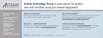
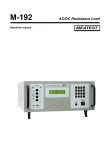
(4) Temperature Sensor Terminals
Source+
SenseSource-
8. MAINTENANCE
Qualified personnel execute the following instructions only. To avoid
electrical shock, do not perform any servicing other than the operating
instructions unless you are qualified to do so.
8-1. Line fuse replacement
If the fuse blows, the meter would not work. Try to determine and correct
the cause of the blown fuse, then replace the fuse with correct rating and
type shown as below:
FUSE RATING AND TYPE
100/120V
TT0.3A 250V
220/230V
T0.25A 250V
F101 on PCB
T6.3A 250V
WARNING: For continued fire protection, replace only
with 250V fuse of the specified type and rating, and
disconnect the power cord before proceeding fuse
replacement.
8-2. Line voltage conversion
The primary winding of the power transformer is tapped to permit
Sense+
operation from 100/120V, or 220/230V AC 50/60Hz line voltage.
Conversion from one line voltage to another is done by changing the line
voltage selector switch as shown in Figure 4-2. The rear panel identifies
the line voltage to which the unit was factory set. To convert to a
different line voltage, perform the following procedure:
⎯ 30 ⎯
⎯ 31 ⎯
GOM-802 DC MILLI-OHM METER
USER MANUAL
1) Make sure the power cord is unplugged.
2) Adjust the line voltage selector switch to the desired line voltage
position.
3) A change in line voltage may also require a corresponding change
of fuse value. Install the correct fuse value as listed on rear panel.
8-3. Cleaning
To keep the instrument clean, wipe the case with a damp cloth and
detergent. Do not use abrasives or solvents.
⎯ 32 ⎯