1
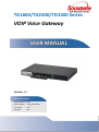
TG1600/TG2400/TG3200 Series
VOIP Voice Gateway
USER MANUAL
Version: 1.1
Default Login Details
WAN IP Address: DHCP
LAN IP Address:
http://192.168.1.1
User Name:
root
Password:
root
Preface ..................................................................................................................................... 5
0.1 About this manual ........................................................................................................... 5
0.2 Copyright ........................................................................................................................ 5
0.3 Trademark....................................................................................................................... 5
0.4 Safety Instructions ........................................................................................................... 5
0.5 Repair Warranty .............................................................................................................. 5
Introduction .............................................................................................................................. 6
1.1 Overview ......................................................................................................................... 6
1.2 Acronyms Table ............................................................................................................... 6
1.3 Introduction .................................................................................................................... 7
1.4 Front panel LED description ............................................................................................. 8
1.5 Product Specifications ..................................................................................................... 9
Installation and setting............................................................................................................ 11
2.1 packing contents ........................................................................................................... 11
2.2 Hardware Installation .................................................................................................... 12
2.3 8 port/16 port/24 port/32 port Series module extension install ..................................... 13
2.4 Quick Start .................................................................................................................... 14
Network setting ...................................................................................................................... 15
3.1 Internet ......................................................................................................................... 15
3.1.1 Static IP ...................................................................................................................... 16
3.1.2 DHCP Mode ................................................................................................................ 17
3.1.3 PPPoE Mode ............................................................................................................... 18
3.1.4 PPTP with WAN (Static, DHCP, PPPoE) ........................................................................ 19
3.1.5 L2TP with WAN (Static, DHCP, PPPoE)......................................................................... 20
3.2 LAN interface ................................................................................................................ 21
3.2.1 User list ...................................................................................................................... 21
2
3.3 Dynamic DDNS .............................................................................................................. 22
3.4 QOS setting ................................................................................................................... 23
3.5 NAT Mode / Bridge mode .............................................................................................. 23
SIP Setting............................................................................................................................... 24
4.1 SIP setting ..................................................................................................................... 24
4.1.1 Proxy server setting .................................................................................................... 24
4.1.2 SIP Advance Setting .................................................................................................... 26
4.1.3 Codec ......................................................................................................................... 27
4.1.4 Line DC Feed Setting ................................................................................................... 27
4.2 Telephone function ....................................................................................................... 28
4.2.1 Call Forward Setting ................................................................................................... 28
4.2.2 Speed Dial .................................................................................................................. 29
4.2.3 Dialing Plan ................................................................................................................ 29
4.2.4 Do Not Disturb ........................................................................................................... 30
4.2.5 Hotline Setting............................................................................................................ 30
4.2.6 Caller ID display .......................................................................................................... 31
4.3 DSP ............................................................................................................................... 31
4.3.1 Volume Control .......................................................................................................... 31
4.3.2 Current control loop ................................................................................................... 32
4.3.3 Flash Hook.................................................................................................................. 33
4.3.4 SLIC Setting ................................................................................................................ 33
4.3.5 Polarity Reversal ......................................................................................................... 34
Advance setting ...................................................................................................................... 35
5.1 NAT Traversal ................................................................................................................ 35
5.2 Phone setting ................................................................................................................ 35
5.2.1 Common .................................................................................................................... 35
5.2.2 Region Tone Setting.................................................................................................... 36
3
5.3 DSCP Setting .................................................................................................................. 37
5.4 Voice Prompt ................................................................................................................ 37
Security................................................................................................................................... 38
6.1 Firewall ......................................................................................................................... 38
6.1.1 IP Filter ....................................................................................................................... 38
6.1.2 Mac Filter ................................................................................................................... 38
6.1.3 URL Filter.................................................................................................................... 39
6.1.4 Port Filter ................................................................................................................... 40
6.2 DOS Prevention Setting ................................................................................................. 40
Maintenance........................................................................................................................... 42
7.1 System .......................................................................................................................... 42
7.1.1 Account Setting .......................................................................................................... 42
7.1.2 Time Setting ............................................................................................................... 42
7.2 Tool ............................................................................................................................... 43
7.2.1 Backup / Restore ........................................................................................................ 43
7.2.2 Firmware Upgrade...................................................................................................... 44
7.2.3 Ping testing ................................................................................................................ 44
7.2.4 Restart ....................................................................................................................... 44
Installation structure ............................................................................................................... 46
4
Preface
0.1 About this manual
This manual is intended to help users to the proper use of TG1600/TG2400/TG3200 series VOIP
voice gateway.
The manual will be different based on the different firmware version, the latest content
(specifications) subject to the original notice, if any content in this document is supposed to
change without notice.
0.2 Copyright
All rights reserved for the 2011 Telephony Corporation. All rights reserved. The information
contained in this publication is protected by copyright. Without written permission, no part of
the copy, transmitted, transcribed, or translated into any language, will be stored in a retrieval
system, ownership of copyright owners.
0.3 Trademark
Appear in this manual product and company names may be related to the company's
registered trademark that appears in this manual product and company names used only for
identification or explanation.
0.4 Safety Instructions
Use only the required power supply voltage. Power input: AC 100 - 240V, 50 - 60 Hz. To reduce
the risk of electric shock, do not disassemble this product. Opening or removing components
could be dangerous. Incorrect assembly may result in abnormal or damaged product, please
refer to the instruction manual before use.
Do not place any objects or liquid into the device, may cause electric shock, abnormal or
damaged products. Products will not produce any liquid. If the product is found around the
liquid leaks, identify and find the appropriate service personnel.
Use the unshielded twisted pair (UTP) Ethernet cable connection RJ - 45 port.
0.5 Repair Warranty
Users buy TG1600/TG2400/TG3200 series VOIP voice gateway products from the dealer have
one year warranty. Be sure to obtain proof of purchase to the dealer and keep it. During the
warranty period, if the product has any abnormalities, failure resulting in the not function
proper, we will evaluate the repair fee or replacement of defective products or parts without
charge. If the product is modified, abuse, tampering, destruction by improper use, or under
abnormal operating conditions, such behavior is not apply the warranty policy. This warranty
does not include other ancillary products authorized software vendor or accessories.
5
1
Introduction
TG1600/TG2400/TG3200 Series VoIP Gateway (VOIP Gateway) and Call Manager (Call Manage)
include low-to high-end Internet telephony overall solution. This article describes how to use
the Voice Gateway (VOIP Gateway) and Call Manager (Call Manage).
1.1 Overview
Internet Telephony Gateway (VOIP Gateway) is a communications device that can be
integrated analog phone, PSTN, or PBX trunk card/extension card.
By Modular hardware design TG1600/TG2400/TG3200 series makes different
combination of the telephone interface. By modular installation, this revolutionary
compact voice over IP (VoIP) gateway could be easily configured as 16/24/32 channels
high density FXS/FXO VoIP Gateway which provides voice connectivity over the IP
network and to the Public Switched Telephone Network (PSTN).
Provide a direct analog port. For computer modulation decoders, fax machines, analog
phones and other devices, the analog port is necessary.
Support for standard Internet services such as NAT, Dynamic DNS (DDNS), Quality of
Service (QoS), Port Filtering, IP Filtering.
1.2 Acronyms Table
Acronym:
Full Name:
Acronym:
Full Name:
API
Application Interface
ACI
Audio CODEC Interface
ADC
Analog to Digital Converter
CODEC
Coder / Decoder
DAC
Digital to Analog Converter
DC
Direct Current
DDNS
Dynamic Domain Name System
DHCP
Dynamic Host Configuration
Protocol
DMZ
Demilitarized Zone
DNS
Domain Name System
DTMF
Dual Tone Multi Frequency
FXO
Foreign Exchange Office
FXS
Foreign Exchange Station
GMT
Greenwich Mean Time
IP
Internet Protocol
IPSec
Internet Protocol Security
L2TP
The Layer 2 Tunnel Protocol
LAN
Local Area Network
WAN
Wide Area Network
MAC
Media Access Control
MII
Media Independent Interface
NAT
Network Address Translation
6
NTP
Network
Time Protocol
PPTP
Point-to-Point Tunneling
Protocol
RTP
Real-Time Transport Protocol
RTCP
Real-Time Transport Control
Protocol (also known as RTP
control protocol)
SIP
Session Initiation Protocol
SLIC
Subscriber Line Interface Circuit
STUN
Simple Traversal of UDP through
URI
Uniform Resource Identifier
NATs
TCP
Transmission Control Protocol
UDP
User Gateway gram Protocol
UPnP
Universal Plug and Play
VoIP
Voice Over Internet Protocol
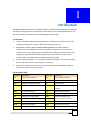
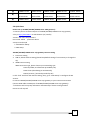
1.3 Introduction
Support SIP VoIP protocol.
TG0800 series: allow 8 SIP calls
TG1600 series: allow 16 SIP calls
TG2400 series: allow 24 SIP calls
TG3200 series: allow 32 SIP calls
Model
FXS Port
TG0800
8
TG0804
4
TG0808
TG1600
16
TG1608
8
TG1616
TG2400
24
TG2412
12
TG2424
TG3200
32
TG3216
16
TG3232
FXO port
WAN Port
LAN Port
RJ-11 port
SIP
1
1
8
4
1
1
8
8
1
1
8
1
1
16
8
1
1
16
16
1
1
16
1
1
24
12
1
1
24
24
1
1
24
1
1
32
16
1
1
32
32
1
1
32
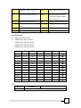
Others:
Model
TG-Host
Description
1 WAN port, 1 LAN port with 1U Rack
7
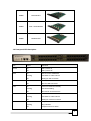
TM800
8FXS Module
TM804
4FXS + 4FXO Module
TM808
8FXO Module
1.4 Front panel LED description
LED
Status
Indication
Power
On
GW is power on
Off
GW is power off
On
GW connection established
Flashing
Data traffic on cable network
Off
Waiting for GW connection
On
USB connected
Off
Wait for USB connected
On
LAN is connected successfully
Flashing
Data is transmitting
Off
Ethernet not connected to PC
On
GW network connection established
Flashing
Data traffic on cable network
Off
Waiting for network connection
On
Telephone Set is Off-Hook
Flashing
Ring Indication
Off
Telephone Set is On-Hook
RUN
USB
LAN
WAN
FXS
8
FXO
On
Line is Off-hook
Off
Line is On-hook
1.5 Product Specifications
Telephone Feature
Voice Codec: G.711 / G.729 / G.723 / G.726
Battery Reverse Generation
Off-Hook Loop Current Configuration
Ring Voltage Configuration
Internet Failed / Register Failed by pass PSTN
DTMF Relay support : In-Band / RFC-2833 / SIP-Info
Voice channels status display: Display each port status like as ON-Hook, OFF-Hook,
calling number.
FAX support : T.38 FAX / FAX by G.711 pass-through
AC termination Impedance : 600/900 OHM and complex impedance
Answer Supervision for polarity reverse detection
IP Specifications:
SIP (RFC 3261), SDP (RFC 2327), STUN (RFC3489) ,RTP Payload for DTMF Digits
(RFC2833) SIP Session Timers (RFC 4028), DNS SRV (RFC 2782) , Outbound
Proxy Support , SIP REFER method (RFC 3515), Early Media and Ringing Tone
Generation (RFC 3960), Message Waiting Indicator (RFC 3842)
WAN: PPPoE client, DHCP client, Fix IP Address, PPTP
Support PPTP/L2TP VPN Client
NAT Functions
DSCP configuration
QoS : DSCP / VLAN Tag
Network and Security specifications
Port Filter
IP Filter
MAC Filter
Call Feature
Adjustable Volume
VAD / Dynamic Jitter Buffer
Caller ID Generation : DTMF CID / FSK CID / NTT CID
Peer-to-Peer Call by Dial Plan
Different Country Tone Table Configuration
Configuration and Management
Web-Based Graphical UI Configuration
HTTP Firmware Upgrade
9
SNMP v1/v2 (Customization Project)
IVR
Provision
TR069/TR098/TR104 (Project Base)
Auto-Provision by HTTP/TFTP/FTP (Project Base)
General Specification
AC power: AC100V-240V, DC12V/2.5A, 50/60 Hz
Temperature: 0°C ~ 40°C (Operation)
Humidity: up to 90% non-condensing
Emission: FCC Part 15 Class B, CE Mark, RoHS Compliant
Dimension : 435x255x45 mm
Weight: 3000 g
10
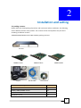
2
Installation and setting
2.1 packing contents
Please check the closed packing of products and accessories before installation. The following
are the default contents of the product. The contents of the actual product may be varied
according to different versions.
TG1600/TG2400/TG3200 series VOIP Gateway packing contents
TG-Host
TM800 module
Adapter
TM804 module
RG-45 cable
TM808 module
User manual
TG0800 series packing contents
TG-Host
X1
TM800/TM804/TM808 module
X1
RJ-45cable
X1
AC adaptor (2.5 A)
X1
11
CD-Rom (user manual)
X1
TG1600 series packing contents
TG-Host
X1
TM800/TM804/TM808 module
X2
RJ-45cable
X1
AC adaptor (2.5 A)
X1
CD-Rom (user manual)
X1
TG2400 series packing contents
TG-Host
X1
TM800/TM804/TM808 module
X3
RJ-45cable
X1
AC adaptor (2.5 A)
X1
CD-Rom (user manual)
X1
TG3200 series packing contents
TG-Host
X1
TM800/TM804/TM808 module
X4
RJ-45cable
X1
AC adaptor (2.5 A)
X1
CD-Rom (user manual)
X1
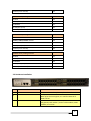
2.2 Hardware Installation
item
Connect interface
Function
1
2
FXS
FXO
3
WAN
FXS port connected to phone or pbx outbound card.
FXO port connected to PBX inbound card or CO line
Back up for life line support, it’s used for PSTN call if
VOIP Call fail.
Connected to internet. The WAN port is able to connect
the gateway and modem ( such as cable modem, ADSL
modem) to internet.
12
Connected to PC or switch /hub. Let your PC or Switch
/hub connected gateway to create LAN environment.
Push the reset bottom till 3 sec. Gateway will be set to
default
4
LAN
5
RESET bottom
6
AC power(DC in 12V)
Power input
2.3 8 port/16 port/24 port/32 port Series module extension install
TG0800/TG1600/TG2400/TG3200 series, according to different module board
(TM800/TM804/TM808) and TG-Host device combine to 8/16/24/32 port high level gateway.
TG-Host: 1 WAN port, 1 LAN port with 1U Rack
TM800: 8FXS module
TM804: 4FXS+4FXO module
TM808: 8FXO module
The models are as follows:
TG-Host
Module_1
Module_2
Module_3
Module_4
Model
TM800: 8 FXS
TG0800: 8FXS
TM804:
TG0804:
4FXS+4FXO
4FXS+4FXO
TM808: 8FXO
TG0808: 8FXO
TM800: 8 FXS
TM800: 8 FXS
TG1600: 16FXS
TM804:
TM804:
TG1608:
4FXS+4FXO
4FXS+4FXO
8FXS+8FXO
TM808: 8FXO
TM808: 8FXO
TG1616: 16FXO
TM800: 8 FXS
TM800: 8 FXS
TM800: 8 FXS
TG2400: 24FXS
TM804:
TM804:
TM804:
TG2412:
4FXS+4FXO
4FXS+4FXO
4FXS+4FXO
12FXS+12FXO
TM808: 8FXO
TM808: 8FXO
TM808: 8FXO
TG2424: 24FXS
13
TM800: 8 FXS
TM800: 8 FXS
TM800: 8 FXS
TM800: 8 FXS
TG3200: 32FXS
TM804:
TM804:
TM804:
TM804:
TG3216:
4FXS+4FXO
4FXS+4FXO
4FXS+4FXO
4FXS+4FXO
16FXS+16FXO
TM808: 8FXO
TM808: 8FXO
TM808: 8FXO
TM808: 8FXO
TG3232: 32FXO
2.4 Quick Start
How to set up TG1600/TG2400/TG3200 series VOIP gateway?
1. connect your PC or NB to LAN port of TG1600/TG2400/TG3200 series voip gateway
2. key in http://192.168.1.1 on web browser (IE / Firefox)
3. enter user name and password
User name: admin
password: admin
4. Enter wizard mode
1. Connection Setup
2. VOIP Setup
TG1600/TG2400/TG3200 series voip gateway internet setting
1. Time zone setting
2. LAN IP, subnet mask IP setting (please keep default setting if not necessary to change the
IP))
3. WAN internet setting
WAN connection type, please choose your networking type
Static IP (fixedIP, IP information provided by ISP)
DHCP Clinet (distributing IP automatically)
PPPoE (account / password provided by ISP)
5. click “end” and finish the internet setting, then, go to “VOIP Setup” to configure the SIP
account.
6. connect TG1600/TG2400/TG3200 series voip gateway to your internet environment
(connect RJ45 cable to WAN port of TG1600/TG2400/TG3200 series voip gateway).
7. The device will set up voip information automatically if devices setting finished
8. Start to call voip call
14
3
Network setting
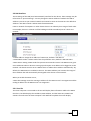
3.1 Internet
WAN (Wide Area Network) is a network connection connecting one or more LANs together
over some distance. For example, the means of connecting two office buildings separated by
several kilometers would be referred to as a WAN connection. The size of a WAN and the
number of distinct LANs connected to a WAN is not limited by any definition. Therefore, the
Internet may be called a WAN.
WAN Settings are settings that are used to connect to your ISP (Internet Service Provider). The
WAN settings are provided to you by your ISP and often times referred to as "public settings".
Please select the appropriate option for your specific ISP.
For most users, Internet access is the primary application. TG1600/TG2400/TG3200 series voip
gateways support the WAN interface for internet access and remote access. The following
sections will explain more details of WAN Port Internet access and broadband access setup.
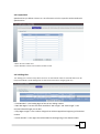
When you click “WAN Setting”, the following setup page will be shown. Three methods are
available for Internet Access.
1. Static IP
2. DHCP
3. PPPoE
15
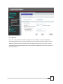
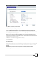
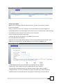
3.1.1 Static IP
If you are a user with static IP address, please enter the IP address, subnet mask, default
gateway and DNS servers, which are provided by your ISP (Internet Service Provider). Each IP
address must be entered in the field of IP in the appropriate forms, which are four IP octets
separated by points (XXXX). Router will not be accepted if IP address not like in this format. For
example: 168.95.1.2
16
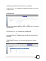
□IP Address: Check with your ISP provider.
□Subnet Mask: Check with your ISP provider.
□Default Gateway: Check with your ISP provider.
□MTU size: MTU stands for Maximum Transmission Unit, the largest physical packet size,
measured in bytes that a network can transmit. Any messages larger than the MTU are divided
into smaller packets before being sent.
The key is to be deciding how big your bandwidth pipe is and select the best MTU for your
configuration. For example, you have a 33.6 modem, you use a MTU of 576, and if you have a
larger pipe you may want to try 1500.
□DNS server: enter DNS server (suggest default setting)
□Enable Keep Alive
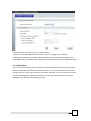
3.1.2 DHCP Mode
Dynamic Host Configuration Protocol (DHCP), Dynamic IP (Get WAN IP Address automatically).
If you are connected to the Internet through a Cable modem line, then a dynamic IP will be
assigned.
Note: WAN port gets the IP Address, Subnet Mask and default gateway IP address
automatically, if DHCP client is successful.
17
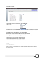
□Name of service: it may be set by your own or blank
□MTU size: enter MTU (Maximum transmission unit) size (suggest set to default)
□Assign DNS Dynamically: get DNS IP address WAN interface automatically (suggest use it)
□First DNA server, Second DNS server: Manually enter the domain name server WAN interface
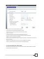
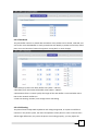
3.1.3 PPPoE Mode
Point-to-Point Protocol over Ethernet (PPPoE). Some ISPs provide DSL-based services and use
PPPoE to establish communication link with end-users. If you are connected to the Internet
through a DSL line, check with your ISP to see if they use PPPoE. If they do, you need to make
sure the following items, PPPoE User name: Enter username provided by your ISP. PPPoE
Password: Enter password provided by your ISP.
18
□USER name: the user name provided by your ISP
□user password: enter password provided by your ISP
□Name of service: you may set up the name of service or blank
□Type of connection:
Continuous: will keep trying to connect internet while disconnect
Connect on demand: will be set according to the idle time when connection
□Manual: connect or disconnect by manual
□Idle time: when the connection type is: Connect on demand, can set up the interval time to
reconnect internet
□MTU size: enter MTU (max transmission unit) size (suggest set to default)
□Server 1,2: Manually enter the domain name server WAN interface
3.1.4 PPTP with WAN (Static, DHCP, PPPoE)
Some ISPs provide DSL-based service and use PPTP with Static, DHCP or PPPoE to establish
communication link with end-users.
19
□PPTP Server IP Address: check with your VPN /PPTP Server provider
□PPTP User Name: PPTP Dial-in account
□PPTP Password: PPTP Dial-in Password
□PPTP MTU Size
□Request MPPE Encryption
□Remote LAN setting: select SIP Call by LAN IP Address or not
3.1.5 L2TP with WAN (Static, DHCP, PPPoE)
Some ISPs provide DSL-based service and use L2TP with Static, DHCP or PPPoE to establish
communication link with end-users.
□L2TP Server IP Address: check with your VPN /L2TP Server provider
□L2TP User Name: L2TP Dial-in account
□L2TP Password: L2TP Dial-in Password
□L2TP MTU Size
□Request MPPE Encryption
□Remote LAN setting: select SIP Call by LAN IP Address or not
20
3.2 LAN interface
The IP settings of the LAN (Local Area Network) interface for the device. These settings may be
referred to as "private settings". You may change the LAN IP address if needed. The LAN IP
address is private to your internal network and cannot be seen on the Internet. The default IP
address is 192.168.1.1 with a subnet mask of 255.255.255.0.
LAN is a network of computers or other devices that are in relatively close range of each other.
For example, devices in a house or office building would be considered part of a local area
network
□LAN IP Address: Assign the IP address of LAN server, default is 192.168.1.1
□Subnet Mask: Select a subnet mask from the pull-down menu, default is 255.255.255.0.
□DHCP Server Setting: DHCP stands for Dynamic Host Control Protocol. The DHCP server gives
out IP addresses when a device is starting up and request an IP address to be logged on to the
network. The device must be set as a DHCP client to "Obtain the IP address automatically". By
default, the DHCP Server is enabled in the unit. The DHCP address pool contains the range of
the IP address that will automatically be assigned to the clients on the network.
When you enable the DHCP server,
□DHCP Client Range: Enter the starting IP address for the DHCP server’s IP assignment and the
ending IP address for the DHCP server’s IP assignment.
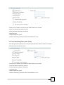
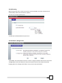
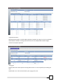
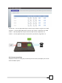
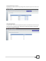
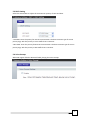
3.2.1 User list
The client computer is connected to the unit will display their information table in the DHCP
client list. The table displays the IP address, MAC address, and the lease time, DHCP lease
statistics for each time the client computer. Click Refresh to update the screen display
21
3.3 Dynamic DDNS
Maintenance of dynamic database of domain names, and the corresponding "Internet
Protocol"(IP) address
DNS: is a core Internet services, as domain names and IP addresses can be mapped to a
distributed database, can make people more convenient access to the Internet, without having
to remember that the machine can be directly read a string of IP
How to use dynamic domain name service
From this web site you can register a new DDNS service account:
http://www.dyndns.com/newacct
Note that if you are using a fixed IP address, do not set the gateway dynamic domain name.
DDNS and use both a fixed IP, DynDNS DDNS service will stop your DDNS service.
□Enable DDNS: Enable/Disable the DDNS service, default setting is Disable.
□DDNS Server Type: Support two types of DDNS, DynDns.org or TZO.net
□Domain Name: The domain which you register in DynDns.org or TZO.net website.
□DDNS Username : The username which you register in DynDns.org or TZO.net website.
□DDNS Password: The password which you register in DynDns.org or TZO.net website.
22
3.4 QOS setting
When using a VoIP call, in order to ensure the voice bandwidth, the other connection will
automatically reduce the transmission capacity
You can set your Qos upload speed
□Enable QoS: Enable/Disable the QoS service
3.5 NAT Mode / Bridge mode
□NAT Mode: This mode allows LAN users to share a single IP address and Internet connection.
□Bridge Mode: This mode allows the Internet interface and local area network interface
bridging, Notice: the bridge mode failure once you start NAT and firewall
23
4
SIP Setting
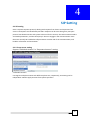
4.1 SIP setting
SIP is a request-response protocol, dealing with requests from clients and responses from
servers. Participants are identified by SIP URLs. Requests can be sent through any transport
protocol. SIP determines the end system to be used for the session, the communication media
and media parameters, and the called party's desire to engage in the communication. Once
these are assured, SIP establishes call parameters at either end of the communication, and
handles call transfer and termination.
4.1.1 Proxy server setting
Support “Individual Account” or “Represent Account” setting.
□Individual Account:
Can register multiple accounts with different phone use, respectively, accounting can be
independent. Need to apply account from System operators
24
□Represent Account:
Representative number is used for PBX integration, between the objects can only remember a
representative number is enough, but the account can’t be independent. Need to apply
account from System operators
□Ring type:
Ring by order: Each time sequence starting from the line 1 is not occupied by line looking for
ring
Round Robin: Turn calls increased each cycle, ringing every user
25
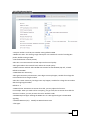
4.1.2 SIP Advance Setting
□SIP port number: Local SIP port number setting defaults:5060
□Media Port Start: The starting range of RTP port. Port number for initial of sending RTP
packet, default setting is 9000.
□RTP Packetization interval (Ptime):
Value less: Increase network load and improve the sound quality
Value gain: Reduce the network load, reduce the sound quality.
□DTMF Transmit method: Select DTMF transmission format RFC2833, Sip info, In band.
Default is RFC2833
□DTMF detection Sensitivity:
Value gain: Sensitivity enhancement, more digit issue may happen, suitable for enlarge the
item when dial short length number
Value less: Lower sensitivity, less digit issue may happen, suitable for enlarge the item when
dial the long length number.
Default is -1
□DTMF volume: Sometimes no action when dial, you may adjust the function.
For example: when you make call to a company, you get a IVR, but no action when dial the
extension number, you may increase the value. Default is 0dB
□RFC2833 Payload Type: Sending the DTMF tone as a RTP payload signal. The RFC2833
signaling
□SIP INFO Duration (ms): Modify SIP INFO duration time.
□FAX type:
26
G711 fax pass through (not compressed by using a 64Kbps channel to transmit voice signals)
T.38 fax relay (fax encoded by IP protocol)
□SIP Account Pooling: SIP account sharing
□Local Port call directly
□SIP Invite timeout
4.1.3 Codec
A CODEC is an algorithm for taking voice or video and compressing the information. This type
of codec combines analog-to-digital conversion and digital-to-analog conversion functions in a
single chip. The Codec is used to compress the voice signal into data packets. Each Codec has
different bandwidth requirement. There are 9 kinds of codec, G.711/Ulaw, G.711/Alaw, G.729,
G.723(5.3k / 6.3k bps), G.726(16K bps), G.726(24K bps), G.726(32K bps), G.726(40K bps),
GSM-FR
4.1.4 Line DC Feed Setting
27
Port 1: on /off line 1 function.
Port 2: on /off line 2 function.
Port 3: on /off line 3 function.
Port 4: on /off line 4 function.
4.2 Telephone function
4.2.1 Call Forward Setting
You can setup the phone number you want to forward in this page. There are three type of
Forward mode. You can choose Immediate Forward, Busy Forward, and No Answer Forward
by click the icon.
Immediate Forward: All incoming call will forward to the number you choose. You can input the
phone number. If you select this function, then all the incoming call will direct forward to the
speed dial number you choose.
28
4.2.2 Speed Dial
Speed Dial lets you define a button or a set of buttons to link to a specific number defined in
Speed Dial list.
□Name: Phone number note.
□Phone Number: Enter the international number to dial.
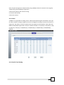
4.2.3 Dialing Plan
The “Dialing plan” needs to setup when the users use the method of Peer-to-Peer SIP VoIP call or SIP
Proxy Server Mode. The SIP Dialing Plan has two kinds of directions: Outgoing (call out).
□“Lead Number” is the leading digits of the call out dialing number.
□“Min-Max Digits” has two text fields need filled: “Min Length” and “Max Length” is the
min/max allowed length you can dial.
□“Strip Digits Length” is the number of digits that will be stripped from beginning of the dialed
number.
□“Prefix Number” is the digits that will be added to the beginning of the dialed number.
29
□“Destination IP/ URL” is the IP address / Domain Name of the destination
TG1600/TG2400/TG3200 series voip gateway that owns this phone number.
□“Destination SIP Port” is port of the destination TG1600/TG2400/TG3200 series voip gateway
use.(Default is 5060)
4.2.4 Do Not Disturb
DND Setting: you can setup the DND Setting to keep the device silence. You can choose Always
or Enable or Disable.
DND Always: All incoming call will be blocked until disable this feature.
DND Enable: Set Enable and the device will be blocked during the time period. If the “From”
time is large than the “To” time, the Block time will from 00:00 to 23:59
When you finished the setting, please click the Submit button.
If there is nothing need to change, please click the Save Change Item in the left side, then click
the Save button. The change you made will save into the system and the system will reboot
automatically.
4.2.5 Hotline Setting
This function allows you to make a call to a pre-programmed number by only lifting the
handset.
30
4.2.6 Caller ID display
Caller ID mode: support FSK_Bellcore, FSK_ETSI, FSK_BT, DTMF
FSK Date and time synchronization: Enable FSK single sending date and time to show on phone
screen
FSK Date & Time Sync: Send FSK Date & Time to display device.
Reverse Polarity before Caller ID: Send Reverse Polarity before Caller ID
Short Ring before Caller ID: Send short ring before caller ID.
Dual Tone before Caller ID: Send Dual Tone before Caller ID.
Caller ID prior First Ring: Send Caller ID before first ring.
Caller ID DTMF Start Digit: Set Caller ID DTMF start digit.
Caller ID DTMF END Digit: Set Caller ID DTMF start digit.
4.3 DSP
4.3.1 Volume Control
Adjust the volume via each port. There are 2 chips have volume adjust function in GW, one is
DSP, another is SLIC
31
□Phone Out:You may adjust DSP chip to control out put volume, rang from -32~31dB
□Phone In:You may adjust DSP chip to control in put volume , range from -32~31dB
□FXS Tx:YOU may adjust SLIC chip to control out put volume, range from 1~ 9
□FXS Rx:You may adjust SLIC chip to control the in put volume, range from 1~9
4.3.2 Current control loop
Telephone interface for each group can do loop current control, and adjust your current
control for PBX or phone
32
4.3.3 Flash Hook
The jitter buffer control is a shared data area where voice packets can be stored, collected, and
sent to the voice shared Buffer in evenly spaced intervals. Modify in packets arrival time, called
jitter, can occur because of network congestion, timing drift, or route changes.
□Min delay (ms): Select min delay buffer time.( 40ms – 100 ms)
□Max delay (ms): Select Max delay Buffer time.(130ms – 300ms)
□Optimization factor: Controls quickly the length of the Jitter Buffer is increased when Voice
RTP on the network. Default is 6
□Flash time Setting: Set Min / max storage Flash Time Setting
4.3.4 SLIC Setting
The phone features adjustable impedance and voltage magnitude, in response to different
countries in the phone system, the internal impedance of the phone in some countries there
will be slight differences, may cause the phone not working properly, you may adjust the
33
internal Impedance for your phone.
Ring Voltage: Can adjust your phone ring voltage, when your phone rings are not normal, try to
adjust this setting
4.3.5 Polarity Reversal
As Callee Answer - Check this box to generate line polarity reversal while the remote user picks
up the phone call. As Callee On-Hook - Check this box to generate line polarity reversal while
the remote user hangs off the phone.
34
5
Advance setting
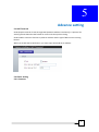
5.1 NAT Traversal
STUN {Simple Traversal of UDP through NATs (Network Address Translation)} is a protocol for
assisting devices behind a NAT firewall or router with their packet routing.
STUN enables a device to find out its public IP address and the type of NAT service its sitting
behind.
When you enable the STUN function, you must input the STUN server address.
5.2 Phone setting
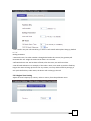
5.2.1 Common
35
□Call transfer: Set your call control keys, it starts to call transfer when phone hang up, default
is “* 1”
Dialing Parameter
□Auto Dial Time: If no other number is being dialed within this interval, the gateway will
terminate this call. Assign the time interval from 1 to 9 seconds.
□Off-Hook Alarm Time: Set has been off-hook, after this time, user will hear alarm.
□FXS off-Hook Debounce: For example, if the value is 10ms, user needs to push the flash key
longer than 10ms to hang up the call. For any reason, user may dial the flash key wrongly, if
user push the flash key under 10ms, the device will not hang up the call.
5.2.2 Region Tone Setting
Adjust the tone frequency by country. Select a country from the pull-down menu.
36
5.3 DSCP Setting
Select the SIP and RTP to adjust the transmission priority of voice and data.
□SIP DSCP: enter the priority for SIP voice transmission. The device creates type of service
priority tags; with this priority to voice traffic that is transmits.
□RTP DSCP: enter the priority for RTP voice transmission. The device creates type of service
priority tags; with this priority to RTP traffic that is transmits
5.4 Voice Prompt
When SIP register failed or Network failed, playing the Voice Prompt.
37
6
Security
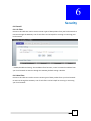
6.1 Firewall
6.1.1 IP Filter
Entries in this table are used to restrict certain types of data packets from your local network to
Internet through the Gateway. Use of such filters can be helpful in securing or restricting your
local network.
□ Enable/Disable IP Filtering: The IP address filter function, control a network IP address from
your local network to Internet through the Gateway, default setting is disable.
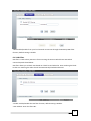
6.1.2 Mac Filter
Entries in this table are used to restrict certain types of data packets from your local network
to Internet through the Gateway. Use of such filters can be helpful in securing or restricting
your local network.
38
□MAC Enable/Disable: from your local network to Internet through the Gateway MAC filter
function, default setting is disable.
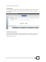
6.1.3 URL Filter
URL filter is used to deny LAN users from accessing the internet. Block those URLs which
contain keywords listed below.
URL filter allows you to block sites based on a black list and white list. Sites matching the black
list but not matching the white list will be automatically blocked and closed.
□Enable: Enable/Disable the URL filter function, default setting is Disable.
□URL Address: Enter the filter URL.
39
Example: “http://www.yahoo.com/”
6.1.4 Port Filter
Entries in this table are used to restrict certain types of data packets from your local network to
Internet through the Gateway. Use of such filters can be helpful in securing or restricting your
local network
6.2 DOS Prevention Setting
Against distributed denial of service attack (DoS) attacks, turn on this feature can be stopped
to prevent problems resulting from access to certain resource, you can check the options
related to denial of service
40
41
7
Maintenance
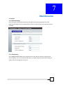
7.1 System
7.1.1 Account Setting
Users can log in via the web interface by entering the username and password to view
administration pages. Only the administrator account has permissions to change user account
password
7.1.2 Time Setting
The TG1600/TG2400/TG3200 series voip gateway set the date and time by using the Time
Protocol (SNTP). You can manually set the timer, or enable automatic time server settings to
update the time through the time server.
42
□Time Zone Select: Choose your time zone
□NTP Server: Select NTP server.
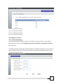
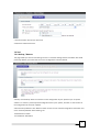
7.2 Tool
7.2.1 Backup / Restore
This page allows you save current settings to a file or reload the settings from the file which was saved
previously. Besides, you could reset the current configuration to factory default.
□Backup: click “Backup” button to save the current configuration of your system to your computer.
□Restore: To restore a previously saved configuration file to your system, “browser” to the location of
the configuration file and click “Upload”
□Back to Factory Defaults: click “Default” button to clear all user-entered configuration information and
return to factory defaults. After resetting, the
-Password will be admin
-Lan IP Address: 192.168.1.1
43
-DHCP will be reset to server
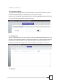
7.2.2 Firmware Upgrade
This page allows you upgrade the Access Point firmware to new version. Please note, do not
power off the device during the upload because it may crash the system.
Notice: It won’t change the system parameter you set when upgrading firmware, but better
you save the system setting before upgrade firmware.
7.2.3 Ping testing
Network traffic diagnostic tools can be used to check the TG1600/TG2400/TG3200 series voip
gateway is connected to the Internet. It will send ping packets to a remote target location of a
particular host, and test whether the link. Enter the address in the target host name or IP
address (for example: www.ippbx.com or 216.115.108.245), then click the "test" button.
7.2.4 Restart
44
Click “Restart” button to restart the device. For some reasons, the device is not responding
correctly, if you want to restart the TG1600/TG2400/TG3200 series voip gateway, you can just
click the Restart button, than the VoIP equipment will reboot automatically.
45
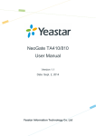
8
Installation structure
8.1 Installation structure
(FXS Gateway)
46