1
Allen-Bradley
ControlNet PLC-5
Hot Backup System
(Includes Cat. No. 1785-CHBM)
User Manual
Important User Information
Solid state equipment has operational characteristics differing from
those of electromechanical equipment. Safety Guidelines for the
Application, Installation, and Maintenance of Solid State Controls,
publication SGI-1.1 describes some important differences between
solid state equipment and hard-wired electromechanical devices.
Because of this difference, and also because of the wide variety of uses
for solid state equipment, all persons responsible for applying this
equipment must satisfy themselves that each intended application of
this equipment is acceptable.
In no event will the Allen-Bradley Company be responsible or liable
for indirect or consequential damages resulting from the use or
application of this equipment.
The examples and diagrams in this manual are included solely for
illustrative purposes. Because of the many variables and requirements
associated with any particular installation, the Allen-Bradley Company
cannot assume responsibility or liability for actual use based on the
examples and diagrams.
No patent liability is assumed by Allen-Bradley Company with respect
to use of information, circuits, equipment, or software described in
this manual.
Reproduction of the contents of this manual, in whole or in part,
without written permission of the Allen-Bradley Company is
prohibited.
Throughout this manual we use notes to make you aware of safety
considerations.
!
ATTENTION: Identifies information about practices
or circumstances that can lead to personal injury or
death, property damage, or economic loss.
Attentions help you:
• identify a hazard
• avoid the hazard
• recognize the consequences
Important: Identifies information that is especially important for
successful application and understanding of the product.
ControlLogix, ControlBus, Logix5550, Data Highway Plus, and PLC-5 are trademarks of Rockwell
Automation.
ControlNet is a trademark of ControlNet International, Ltd.
DeviceNet is a trademark of the Open DeviceNet Vendor Association.
Ethernet is a registered trademark of Digital Equipment Company, Intel, and Xerox Corporation
Publication 1785-6.5.24 February 1999
Preface
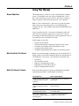
Using This Manual
Manual Objectives
7KLVPDQXDOVKRZV\RXKRZWRXVHWKH&RQWURO1HW3/&%DFNXS
V\VWHP7KLVEDFNXSV\VWHPXVHVDSDLURIVWDQGDUG3/&RU
3/&&RQWURO1HWSURFHVVRUV6HULHV)5HYLVLRQ$RUKLJKHU
ZLWK,2UHPRWHO\FRQQHFWHGWRWKHSURFHVVRUVYLD&RQWURO1HW
1RWH)RUWKH&RQWURO1HW3/&SURFHVVRUVWRRSHUDWHLQEDFNXS
PRGHHDFKSURFHVVRUPXVWKDYHWKHQHZ&RQWURO1HW%DFNXS
&DUWULGJH&DW1R&+%0LQVHUWHGLQWRLWV((3520PHPRU\
PRGXOHVORW
8VLQJ&RQWURO1HWWKH3/&SURFHVVRUVFRPPXQLFDWHZLWKHDFK
RWKHUDQGZLWK&RQWURO1HWUHPRWH,2WRFUHDWHD3/&EDFNXS
V\VWHPWKDWSURYLGHVKLJKDYDLODELOLW\RIFRQWURODSSOLFDWLRQVZKHUHLW
LVHVVHQWLDOIRUSURFHVVFRQWLQXLW\WREHKLJK
,QWKLVPDQXDOZHGHVFULEH
Who Should Use This Manual
%HIRUH\RXUHDGWKLVPDQXDORUDWWHPSWWRXVHWKH&RQWURO1HW3/&
EDFNXSV\VWHP\RXVKRXOGEHIDPLOLDUZLWKWKHXVHDQGRSHUDWLRQRI
&RQWURO1HW3/&SURFHVVRUV<RXVKRXOGDOVREHIDPLOLDUZLWK
What This Manual Contains
EDFNXSV\VWHPFRQFHSWV
KDUGZDUHDQGVRIWZDUHFRPSRQHQWVUHTXLUHGIRUWKHV\VWHP
SURFHGXUHVIRULQVWDOOLQJDQGFRQILJXULQJWKHV\VWHP
RSHUDWLRQRIWKHEDFNXSV\VWHP
WURXEOHVKRRWLQJGLDJQRVWLFVSURFHGXUHVIRUWKHEDFNXSV\VWHP
UHPRWH,2
WKH&RQWURO1HWQHWZRUN
56/RJL[SURJUDPPLQJVRIWZDUH
561HW:RU[IRU&RQWURO1HWVRIWZDUH
56/LQ[FRPPXQLFDWLRQVVRIWZDUH
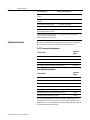
Refer to the following table to guide you through the information
contained in this manual. ,QWKLVPDQXDOZHGHVFULEH
For information on:
Refer to chapter/appendix:
concepts for using a backup system in 1 - Backup Concepts for the ControlNet PLC-5
a ControlNet system; basic system
Backup System
architecture
the hardware and software
components required for a backup
system
2 - Understanding the ControlNet PLC-5 Backup
System Components
installing backup system components;
configuring the backup system
3 - Installing and Configuring Your ControlNet
PLC-5 Backup System
the diagnostic capabilities of the
4 - Monitoring and Troubleshooting Your
backup system; troubleshooting tips for ControlNet PLC-5 Backup System
the backup system
Publication 1785-6.5.24 February 1999
ii
Using This Manual
For information on:
Refer to chapter/appendix:
specifications for the 1785-CHBM
module
A - Specifications
backup states and backup state
transitions
B - Backup States
the data table crossloading feature
C - Data Table Crossloading
the program synchronization feature
D - Program Synchronization
application examples; items to consider E - Application Guidelines
while operating the backup system
reference information on the ControlNet F - Comparison to the 1785-BCM System
backup module for users familiar with
the Allen-Bradley 1785-BCM systems
Related Publications
For more information about components used with the ControlNet
PLC-5 backup system, refer to the following publications:
PLC-5 Processor Documentation
Publication Title
Publication
Number
1785 Enhanced PLC-5 Processor System Overview
1785-2.36
ControlNet PLC-5 Programmable Controllers User Manual
1785-6.5.22
ControlNet PLC-5 Programmable Controllers Quick Start
1785-10.6
PLC-5 Programmable Controller Flash Tool User Manual
1785-6.2
ControlNet Documentation
Publication Title
Publication
Number
ControlNet System Overview
1786-2.12
Industrial Automation Wiring and Grounding Guidelines
1770-4.1
ControlNet Cable System Component List
AG-2.2
ControlNet Cable System Planning and Installation Manual
1786-6.2.1
ControlNet Coax Tap Installation Instruction
1786-2.3
ControlNet Network Access Cable Installation Instructions
1786-2.6
ControlNet Repeater Installation Instructions
1786-2.7
For more information on any of the software components of the
ControlNet PLC-5 backup system (e.g., RSLogix 5, RSLinx, and
RSNetWorx), refer to the software documentation and online help for
the individual software packages.
Publication 1785-6.5.24 February 1999
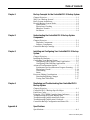
Table of Contents
Chapter 1
Backup Concepts for the ControlNet PLC-5 Backup System
Chapter Objectives ............................................................... 1-1
Why Use a Backup System? ................................................. 1-1
Basic System Architecture .................................................... 1-2
How the Backup System Works ........................................... 1-2
Qualification ................................................................... 1-3
Equivalence Checking .................................................... 1-3
Bumpless Transfer .......................................................... 1-4
Switchover ...................................................................... 1-4
Chapter 2
Understanding the ControlNet PLC-5 Backup System
Components
Chapter Objectives ............................................................... 2-1
Hardware Components ................................................... 2-1
Software Components ..................................................... 2-1
ControlNet Backup Cartridge ............................................... 2-2
Chapter 3
Installing and Configuring Your ControlNet PLC-5 Backup
System
Chapter Objectives ............................................................... 3-1
Installing the Hardware ........................................................ 3-1
Configuring Your Backup System ....................................... 3-2
Configuring With a Single Control Application ............. 3-2
Configuring With Differing Applications ...................... 3-7
Advanced Configuration Options ....................................... 3-12
Synchronous and Asynchronous Program Scanning .... 3-13
Equivalence Checks ...................................................... 3-14
Crossloading
3-15
Status
3-16
Processor Editing Considerations ....................................... 3-17
Downloading Editing Changes
3-17
Testing Data Table Edits
3-17
Chapter 4
Monitoring and Troubleshooting Your ControlNet PLC-5
Backup System
Chapter Objectives ............................................................... 4-1
ControlNet PLC-5 Backup-Specific Major
Fault Error Codes .................................................................. 4-1
Using the 1785-CHBM Cartridge Status Indicators ............. 4-2
Troubleshooting the Invalid Backup State ........................... 4-3
Troubleshooting Qualification Major Faults ........................ 4-4
Troubleshooting Qualification Crossloads ........................... 4-5
ControlNet Backup Configuration and Status File ............... 4-5
Appendix A
Specifications
Specifications ........................................................................A-1
1785-6.5.24 February 1999
ii
Appendix B
Backup States
Chapter Objectives ............................................................... B-1
Invalid Backup State ...................................................... B-2
No Control Backup State ............................................... B-3
Primary Backup State ..................................................... B-4
Lonely Primary Backup State ........................................ B-4
Secondary Backup State ................................................. B-5
Backup State Transitions ..................................................... B-5
Qualification ................................................................... B-5
Appendix C
Data Table Crossloading
Chapter Objectives ............................................................... C-1
Data Table Crossloading ...................................................... C-1
On-Demand Data Table Crossloads ............................... C-2
Data Table Crossload Time ............................................ C-7
Data Table Crossload Data Latency ............................... C-7
Effect of Data Table Crossloading on the ControlNet Channel
......................................................................................... C-7
Inhibiting Data Table Crossloads ................................... C-7
Data Table Crossload Diagnostics ................................. C-8
Performing Data Table Crossloads Via Your Applications
......................................................................................... C-8
Appendix D
Program Synchronization
Chapter Objectives ............................................................... D-1
Program Synchronization ..................................................... D-1
Determining Which Mode to Use .................................. D-2
Using Synchronous Mode .............................................. D-2
Appendix E
Application Guidelines
Chapter Objectives ................................................................E-1
Redundancy Considerations ..................................................E-1
Switchover Considerations ...................................................E-1
Why Transfer Information? ............................................E-1
What Information Should Be Transferred? .....................E-2
When Should the Information Be Transferred? ..............E-3
How Often Should the Information Be Transferred? ......E-3
Performance Considerations ...........................................E-4
Appendix F
Comparison to the 1785-BCM System
Chapter Objectives ................................................................F-1
Comparison to the BCM System ..........................................F-1
1785-6.5.24 February 1999
Chapter
1
Backup Concepts for the ControlNet
PLC-5 Backup System
Chapter Objectives
This chapter describes concepts for using a backup system with your
programmable controller. In particular, this chapter describes the use
of the ControlNet PLC-5 backup system, including its basic system
architecture.
Why Use a Backup System?
The objective of any redundant system (i.e., backup system) is to
improve the amount of up-time of a machine or process by ensuring
consistent availability of that machine, thereby reducing costs
associated with equipment failure. By using this backup system, you
can help guard your application against shutdowns caused by the
programmable controller.
!
ATTENTION: When using identical programs in both
PLC-5 processors, using a backup system does not
necessarily protect you from faults caused by
programming errors or system timeouts. Such errors or
timeouts can also occur in the secondary processor. Be
certain to carefully check your programming, and to
thoroughly check redundant operations before
implementing the backup system.
The backup option is used where you must transfer the control of the
process to a secondary system without interrupting the
machine/process operation.
To guard against system shutdown, a backup system must provide:
•
•
•
equipment with exceptional reliability
automatic fault isolation
minimal disturbance of the process when switching from the
primary to the secondary system
Publication 1785-6.5.24 February 1999
1-2
Backup Concepts for the ControlNet PLC-5 Backup System
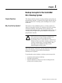
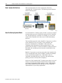
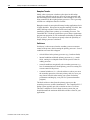
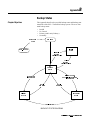
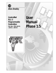
Basic System Architecture
This section describes the various components of the basic
ControlNet PLC-5 backup system. The following picture illustrates
the basic backup system.
How the Backup System Works
In a ControlNet PLC-5 backup system, one PLC-5 processor, referred
to as the primary processor, controls the operation of the ControlNet
I/O. The other processor, referred to as secondary, is set up to take
control of the ControlNet I/O in the event of a fault in the primary
processor.
The ControlNet network is wired to both PLC-5 processors, as well as
to all ControlNet I/O in your system. Using ControlNet, the
processors communicate (or “handshake”) with each other,
exchanging status information on their operational states. If the
primary processor faults, or is otherwise unable to continue control of
the outputs, the secondary processor assumes control and becomes
the primary.
Both PLC-5 processors are actively connected to the ControlNet I/O,
receive all input data sent by the I/O adapters, and then use that data
as they execute their program scans. Output data is sent via
ControlNet from both processors. However, only data from the
primary processor is used by the I/O adapter(s).
In the case of the ControlNet PLC-5 backup system, there are several
features to consider that, though common to many backup systems,
are uniquely implemented in this particular system. Understanding
these features and their functions will help you in the design and
implementation of your backup applications.
Publication 1785-6.5.24 February 1999
Backup Concepts for the ControlNet PLC-5 Backup System
1-3
Qualification
When bringing the secondary processor of a backup system online, it
is important to ensure that it is in a state that will enable it to take over
the control of the system in the event of a primary failure or
switchover. This process of verifying and conditioning the state of
the secondary processor is known as qualification. Switchover will
not occur without a qualified secondary processor; the backup system
is not truly considered a backup system until the secondary processor
has successfully completed qualification.
The qualification phase includes several tests and verifications
between the primary and secondary processors, as well as data file
crossloading. You can tailor these tests, verifications, and data file
crossloads to ensure the level of system integrity required for your
application. These tests and verifications may cover:
•
•
•
•
•
configuration file validity and integrity checking
application program and data file structure equivalence checking
I/O map structure comparison
force table comparison
status file comparison
Data file crossloading from the primary to the secondary processor
may include the transfer of integer values, floating point values,
timers, counters, PID values, and others you define.
Equivalence Checking
Backup systems are traditionally designed in a way such that both the
primary and secondary processors are programmed with identical
applications. This allows for the controlled process to continue with
normal production operation in the event of a primary processor
failure. Equivalence checks ensure that the primary and secondary
processors have identical ladder programs, data file structures, I/O
map structures, etc.. You, as the designer of the backup system,
require the ability to enforce equivalence checks between the primary
and secondary processors during the qualification process, and
periodically during normal production operation.
In some cases, you may want the secondary processor to have a
completely different application than the primary processor (e.g.,
“safe shutdown,” limited production, clean and wash, etc.). In that
case, equivalence checking may not be required. With the ControlNet
PLC-5 backup system, you can enable or disable equivalence
checking as required by your application. You must have a thorough
understanding of your application in order to make this
determination.
Publication 1785-6.5.24 February 1999
1-4
Backup Concepts for the ControlNet PLC-5 Backup System
Bumpless Transfer
Ideally, when a processor switchover takes place in the backup
system, there should be no adverse effect on system operation, and
the controlled process should continue to run as though it were still
being controlled by the original primary processor. This is generally
referred to as a bumpless transfer of control.
Bumpless transfer is not required for many backup applications, but it
is highly desirable. Divergence in program scanning, I/O tables, data
tables, and long switchover times can all cause bumps when
transferring control from a primary to a secondary processor. The
ControlNet PLC-5 backup system allows you to choose synchronous
program scan operation, as well on-demand crossloading of data table
files you select. These options can greatly reduce the possibility of
bumps during a processor switchover.
Switchover
Switchover is what occurs when the secondary processor assumes
control of the process, thus becoming the primary processor. Several
conditions can cause this to happen:
•
critical failures in the primary processor (e.g., hardware faults)
•
internal conditions within the primary processor (e.g., a major
fault), causing it to relinquish control of the process to the secondary processor
•
external conditions recognized by the secondary processor (e.g.,
loss of communications with the primary processor) causing it to
assume control of the process
•
a manual switchover (i.e., a forced switchover, where you cause
the secondary processor to become primary, and vice versa; you
may choose to do this when testing your system for backup
performance and integrity, or as part of a system maintenance
program).
The ideal switchover time from the primary processor to the
secondary processor would be instantaneous. The ControlNet PLC-5
backup system typically provides a switchover time of 30-50 ms.
This time is adequate to avoid a bump in most systems, but you
should determine the maximum allowable switchover time for your
applications.
Publication 1785-6.5.24 February 1999
Chapter
2
Understanding the ControlNet PLC-5
Backup System Components
Chapter Objectives
This chapter describes the components that make up the ControlNet
PLC-5 backup system.
Hardware Components
These components include:
•
two Series F PLC-5 ControlNet processors (either
1785-L40C15/F or 1785-L80C15/F)
Each processor must be in a separate 1771 chassis, and each chassis must have its own power supply. Various chassis and power
supplies are available; choose them based upon standard 1771
and 1785 selection and installation criteria.
Note: Though we do not recommend it, it is possible for you to
use a mixed set of processors as a backup pair (e.g., one
PLC-5/40 and one PLC-5/80).
•
•
•
•
•
•
•
two 1785-CHBM/A ControlNet backup cartridges (one for each
PLC-5 processor)
two 1771 chassis (one for each PLC-5 processor)
two 1771 power supplies (one for each chassis)
You can elect to use redundant power supplies within a chassis if
you wish. We do not recommend the use of I/O within the
chassis, since provisions for backing up the local I/O are not
provided.
one or more ControlNet I/O adapters
ControlNet network cables, taps, and terminators for making
connections between the PLC-5 processors and the I/O adapters
a PC with a 1784-KTCX15 card, or a laptop computer with a
1784-PCC card
other ControlNet devices, including HMI (optional)
Software Components
The basic ControlNet PLC-5 backup system includes the following
software components:
•
RSLogix 5 programming software (Release 3.21 or later)
•
RSNetWorx for ControlNet software (Release 1.08 or later)
•
RSLinx gateway communication software (Release 2.00.97.30 or
later)
Publication 1785-6.5.24 February 1999
2-2
Understanding the ControlNet PLC-5 Backup System Components
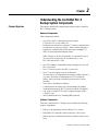
ControlNet Backup Cartridge
Each ControlNet PLC-5 processor requires a 1785-CHBM/A
ControlNet backup cartridge, inserted into the PLC-5 EEPROM
memory cartridge slot, to enable backup functionality.
The ControlNet backup cartridge contains EEPROM memory
cartridge functionality (i.e., the cartridge can also be used as a
standard PLC-5 EEPROM memory storage cartridge for the PLC-5
processor, with up to 100K of memory).
Important: The 1785-CHBM ControlNet backup cartridge cannot
be used with non-backup PLC-5 processors.
Publication 1785-6.5.24 February 1999
Chapter
3
Installing and Configuring Your ControlNet
PLC-5 Backup System
Chapter Objectives
7KLVFKDSWHURXWOLQHVWKHVWHSV\RXPXVWSHUIRUPWRLQVWDOOWKHEDFNXS
V\VWHPFRPSRQHQWVDQGWRVXEVHTXHQWO\FRQILJXUHWKHPWRFUHDWHD
IXQFWLRQLQJEDFNXSV\VWHP
Installing the Hardware
Before you begin, be sure that you have all of the required hardware
components, as listed in Chapter 2.
Follow these steps to install the required hardware for your backup
system.
1. Set the ControlNet node address number for each of the PLC-5
processors.
Important: The node addresses must be consecutive, with the
lower number being odd. For example, a valid node address pair
is 1 and 2. You set the ControlNet node address via the rotary
switches on the top of each processor. You may need to change
the ControlNet node address of other devices so that you have
two consecutive addresses available on your ControlNet network.
2. Install each PLC-5 processor into a separate 1771 chassis.
3. Insert the 1785-CHBM ControlNet backup cartridge into the
EEPROM slot of each PLC-5 processor. (Note that the power
must be OFF on the processor before you do this.)
Important: If the ControlNet backup cartridge is not inserted
into the PLC-5 processor, that processor will operate as a normal,
standalone processor, and will not exhibit any of the necessary
backup functions.
4. Install a power supply for each chassis, and connect to ac power.
5. Wire the ControlNet network to the PLC-5 processors and to the
ControlNet I/O adapters being used for the backup system.
The network cabling may consist of single or redundant channels.
Important: In non-redundant media applications, place your two
PLC-5 processors as the 2 nodes closest to a terminator on a
ControlNet segment. This eliminates the possibility for a
malfunctioning cable between the processors to allow each
processor to control a subset of the I/O.
6. Basic installation is now complete. Set the keyswitch to Program
mode on each processor and apply power to the processors.
Publication 1785-6.5.24 February 1999
3-2
Installing and Configuring Your ControlNet PLC-5 Backup System
Configuring Your Backup System
Before you begin, make sure that you have installed RSLinx,
RSLogix5, and RSNetWorx for ControlNet software. For assistance
with installing any of these packages, refer to their respective
installation documentation.
There are two basic configuration paths. Select the appropriate path
based upon the type of backup system you are creating.
•
If you are creating a backup system with identical (or nearly
identical) control applications in the primary and secondary
controllers, complete the steps in the section of this chapter
entitled “Configuring With a Single Control Application.”
•
If you are creating a backup system where the secondary
controller is running a different application than the primary,
complete the steps in the section of this chapter entitled
“Configuring With Different Applications.”
Configuring With a Single Control Application
This section assumes that you have already developed your control
application and have loaded it onto a single ControlNet PLC-5
processor (i.e., a non-backup system). Throughout this section, we
will refer to this processor as the first processor. Furthermore, we
assume that you have a second processor installed, powered on, and
in its default state. Both processors must be in Program mode and
must be physically connected to your ControlNet network.
To create and configure your backup system under these
circumstances, complete the following steps:
1. Reconfigure ControlNet I/O on the first processor.
2. Configure handshaking messages between both processors.
3. Configure ControlNet I/O on the second processor.
4. Save the ControlNet configuration.
5. Configure the hot backup parameters on the first processor and
save the project.
6. Create and download the project for the second processor and
save the project.
Publication 1785-6.5.24 February 1999
Installing and Configuring Your ControlNet PLC-5 Backup System
3-3
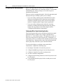
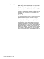
Reconfigure ControlNet I/O on the First PLC Processor
Reconfigure all ControlNet I/O adapters and modules that will be in
your ControlNet PLC-5 backup system by changing their ControlNet
connection from Exclusive Owner (default) to Redundant.
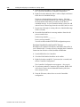
1. Launch RSNetWorx for ControlNet.
2. Check the Edits Enabled checkbox on the toolbar.
3. Right click on the first PLC-5 processor (the odd node) and
choose ControlNet Configuration.
The ControlNet Configuration screen appears.
4. For each entry under the Connection Type column, double click
on Exclusive Owner, choose Redundant from the pull-down
menu, and press Enter.
Configure Handshaking Messages With RSNetWorx
Within your backup system, you must use RSNetWorx to set up the
send and receive scheduled messages that allow handshaking to occur
between the two ControlNet PLC-5 processors that comprise your
backup system.
For each of the processors comprising a backup system, you must
create two scheduled peer-to-peer messages: one Send and one
Receive. These messages must be exactly five words in length. From
the ControlNet Configuration screen for the first processor, follow
these steps:
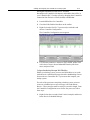
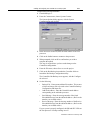
1. Right click on the even node (Node 2 in this example) and choose
Insert Receive Scheduled Message.
Publication 1785-6.5.24 February 1999
3-4
Installing and Configuring Your ControlNet PLC-5 Backup System
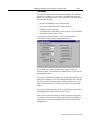
The Receive Scheduled Message dialog appears.
The Node Number field is already filled in for you. This number
indicates the node number from which you will receive the
Receive scheduled message. In your ControlNet backup system,
the odd node will receive the message from the even node, and
vice versa.
2. Enter the message number you wish to assign to identify this
message.
Note that the message number for the Receive message must
match the message number of the corresponding Send message.
The node number and message number are used together to
identify the specific message.
3. In the Requested Packet Interval field, enter an RPI value for this
message from 1 to 32,767. (For purposes of this example, we
will use an RPI value of 5.)
In general, the RPI value must be no less than the NUT value, but
less than 2 times the NUT value. This value must be the same in
both PLC-5 processors.
4. In the Message Size field, enter a value of 5 and click OK.
The Receive scheduled message is inserted in your ControlNet
Configuration for the odd node. The corresponding Send
scheduled message is automatically inserted for the even node.
5. From the main RSNetWorx screen, right click on the second
PLC-5 processor and choose ControlNet Configuration.
6. Right click on the odd node (Node 1 in this example) and choose
Insert Receive Scheduled Message.
The Receive Scheduled Message dialog appears. The Node
Number field is already filled in for you. This number indicates
the node number from which you will receive the Receive
scheduled message. In your ControlNet backup system, the odd
node will receive the message from the even node, and vice versa.
7. Repeat steps 2 through 4, creating a Receive Scheduled Message
for the even node.
Publication 1785-6.5.24 February 1999
Installing and Configuring Your ControlNet PLC-5 Backup System
3-5
8. Record the Send and Receive message numbers from the odd
processor node below:
Send message number:__________
Receive message number:__________
You will use these numbers later in the configuration process.
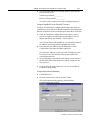
Configure ControlNet I/O on the Second PLC Processor
Configure all ControlNet I/O adapters and modules that will be in
your backup system, and ensure that the ControlNet I/O mapping and
data file assignments on the second processor match those on the first.
1. From the ControlNet Configuration screen (for the second
processor), right click on the node corresponding to your I/O
adapter and choose Auto Module > Selected Device.
All 1794 non-discrete I/O modules on your ControlNet network
are added to your configuration as pending map entries.
2. Enter data table file addresses for the Diagnostics, Status,
Configuration, Data Input, and Data Output files.
Note that these addresses must be the same for both processors.
Be careful to enter file numbers which do not conflict with
existing data table files.
3. Select each adapter and module in the backup system and enter
the data table address that matches the address assigned on the
first processor.
4. From the Network menu, choose Save to save the completed
ControlNet configuration.
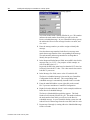
Configure the Hot Backup Parameters
1. Launch RSLogix 5.
2. From the Comms menu, choose System Comms...
The System Options dialog appears, with the System
Communications tab selected.
Publication 1785-6.5.24 February 1999
3-6
Installing and Configuring Your ControlNet PLC-5 Backup System
3. In the Processor Node field, enter the node number of the first
processor.
4. Click on the Online button to connect to the processor.
5. When prompted, click on OK to confirm that you wish to
complete the upload.
This step is required since you have made changes to the
ControlNet configuration.
6. From the File menu, choose Save to save the project.
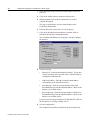
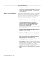
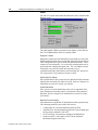
7. Click on the Hot Backup icon under the Controller folder to
launch the Hot Backup Configuration utility.
The ControlNet Hot Backup screen appears, with the Configure
tab selected.
8. Set the following:
•
Backup File - Enter an unused data file number. This creates
a 200-word integer file to be used as the ControlNet Backup
Configuration and Status file.
•
Odd Node Address - Enter the ControlNet node address
corresponding to the odd node processor.
•
Send Message - Enter the message number of the Send
Scheduled Message from the odd node address. (Refer to the
number you recorded earlier.)
•
Receive Message - Enter the message number of the Receive
Scheduled Message from the odd node address. (Refer to the
number you recorded earlier.)
If your system is properly configured, the PRI and SEC LEDs on
the first processor’s backup cartridge are off.
9. Save the configuration.
This completes the backup configuration for the first processor.
Publication 1785-6.5.24 February 1999
Installing and Configuring Your ControlNet PLC-5 Backup System
3-7
Create and Download the Project for the Second PLC Processor
The next step in configuring your system is to duplicate the
fully-configured project from the first processor and apply it to the
second processor.
Important: You must keep the ControlNet configuration you create
for the second processor, since it is not completely identical to that of
the first processor.
1. In RSLogix 5, open the project associated with the first processor
offline.
2. From the File menu, choose Save As, and save the project under a
new name to be associated with the second processor.
3. From the Comms menu, choose System Comms and change the
processor node value from the current standalone processor to the
other processor of the odd-even pair (e.g., if the standalone
processor was processor 1, change the value from 1 to 2.)
4. From the Comms menu, choose Download to download the
project to the new processor.
5. When prompted to decide whether you wish to keep the existing
ControlNet configuration, choose Yes.
Note: This is not the default option.
6. Go online with the new processor.
7. From the File menu, choose Save to save the project.
The QUAL LED on both processors should now be yellow, and
you have a fully qualified backup system. If desired, you can
now go to Run mode.
Configuring With Differing Applications
This section assumes that:
•
you intend for the secondary controller in your backup system to
run a different application than the primary
•
you have already developed separate control applications for the
primary and secondary processors
•
the control applications are loaded onto their respective
processors
•
both processors are powered on, are in Program mode, and are
physically connected to the ControlNet network
•
you have not yet configured these processors to function within a
backup system
Publication 1785-6.5.24 February 1999
3-8
Installing and Configuring Your ControlNet PLC-5 Backup System
To create and configure your backup system under these
circumstances, complete the following steps:
1. Reconfigure ControlNet I/O on the first processor.
2. Configure handshaking messages between both processors.
3. Reconfigure ControlNet I/O on the second processor.
4. Save the ControlNet configuration.
5. Configure the hot backup parameters on the first processor and
save the project.
6. Configure the hot backup parameters on the second processor and
save the project.
Reconfigure ControlNet I/O on the First PLC Processor
Reconfigure all ControlNet I/O adapters and modules that will be in
your ControlNet PLC-5 backup system by changing their ControlNet
connection from Exclusive Owner (default) to Redundant.
1. Launch RSNetWorx for ControlNet.
2. Check the Edits Enabled checkbox on the toolbar.
3. Right click on the first PLC-5 processor (the odd node) and
choose ControlNet Configuration.
The ControlNet Configuration screen appears.
4. For each entry under the Connection Type column, double click
on Exclusive Owner, choose Redundant from the pull-down
menu, and press Enter.
Publication 1785-6.5.24 February 1999
Installing and Configuring Your ControlNet PLC-5 Backup System
3-9
Configure Handshaking Messages With RSNetWorx
Within your backup system, you must use RSNetWorx to set up the
send and receive scheduled messages that allow handshaking to occur
between the two ControlNet PLC-5 processors that comprise your
backup system.
For each of the processors comprising a backup system, you must
create two scheduled peer-to-peer messages: one Send and one
Receive. These messages must be exactly five words in length. From
the ControlNet Configuration screen for the first processor, follow
these steps:
1. Right click on the even node (Node 2 in this example) and choose
Insert Receive Scheduled Message.
The Receive Scheduled Message dialog appears.
The Node Number field is already filled in for you. This number
indicates the node number from which you will receive the
Receive scheduled message. In your ControlNet backup system,
the odd node will receive the message from the even node, and
vice versa.
2. Enter the message number you wish to assign to identify this
message.
Note that the message number for the Receive message must
match the message number of the corresponding Send message.
The node number and message number are used together to
identify the specific message.
3. In the Requested Packet Interval field, enter an RPI value for this
message from 1 to 32,767. (For purposes of this example, we
will use an RPI value of 5.)
In general, the RPI value must be no less than the NUT value, but
less than 2 times the NUT value. This value must be the same in
both PLC-5 processors.
4. In the Message Size field, enter a value of 5 and click OK.
The Receive scheduled message is inserted in your ControlNet
Configuration for the odd node. The corresponding Send
scheduled message is automatically inserted for the even node.
Publication 1785-6.5.24 February 1999
3-10
Installing and Configuring Your ControlNet PLC-5 Backup System
5. From the main RSNetWorx screen, right click on the second
PLC-5 processor and choose ControlNet Configuration.
6. Right click on the odd node (Node 1 in this example) and choose
Insert Receive Scheduled Message.
The Receive Scheduled Message dialog appears. The Node
Number field is already filled in for you. This number indicates
the node number from which you will receive the Receive
scheduled message. In your ControlNet backup system, the odd
node will receive the message from the even node, and vice versa.
7. Repeat steps 2 through 4, creating a Receive Scheduled Message
for the even node.
8. Record the Send and Receive message numbers from the odd
processor node below:
Send message number:__________
Receive message number:__________
You will use these numbers later in the configuration process.
Reconfigure ControlNet I/O on the Second PLC Processor
Reconfigure all ControlNet I/O adapters and modules that will be in
your ControlNet PLC-5 backup system by changing their ControlNet
connection from Exclusive Owner (default) to Redundant.
1. Launch RSNetWorx for ControlNet.
2. Check the Edits Enabled checkbox on the toolbar.
3. Right click on the second PLC-5 processor (the even node) and
choose ControlNet Configuration.
The ControlNet Configuration screen appears. (See page 8.)
4. For each entry under the Connection Type column, double click
on Exclusive Owner, choose Redundant from the pull-down
menu, and press Enter.
5. From the File menu, choose Save to save the ControlNet
configuration.
Publication 1785-6.5.24 February 1999
Installing and Configuring Your ControlNet PLC-5 Backup System
3-11
Configure the Hot Backup Parameters
1. Launch RSLogix 5.
2. From the Comms menu, choose System Comms...
The System Options dialog appears, with the System
Communications tab selected.
3. In the Processor Node field, enter the node number of the first
processor.
4. Click on the Online button to connect to the processor.
5. When prompted, click on OK to confirm that you wish to
complete the upload.
This step is required since you have made changes to the
ControlNet configuration.
6. From the File menu, choose Save to save the project.
7. Click on the Hot Backup icon under the Controller folder to
launch the Hot Backup Configuration utility.
The ControlNet Hot Backup screen appears, with the Configure
tab selected
8. Set the following:
•
Backup File - Enter an unused data file number. This creates
a 200-word integer file to be used as the ControlNet Backup
Configuration and Status file.
•
Odd Node Address - Enter the ControlNet node address
corresponding to the odd node processor.
•
Send Message - Enter the message number of the Send
Scheduled Message from the odd node address. (Refer to the
number you recorded earlier.)
•
Receive Message - Enter the message number of the Receive
Scheduled Message from the odd node address. (Refer to the
number you recorded earlier.)
If your system is properly configured, the PRI and SEC LEDs on
the first processor’s backup cartridge are off.
Publication 1785-6.5.24 February 1999
3-12
Installing and Configuring Your ControlNet PLC-5 Backup System
9. Save the configuration.
10. Repeat steps 1 through 9 for the second processor, saving the
configuration under a different name.
The QUAL LED on both processors should now be yellow, and
you have a fully qualified backup system. If desired, you can
now go to Run mode.
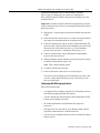
Advanced Configuration Options
The procedures in the previous sections outlined the steps required to
configure a basic ControlNet PLC-5 backup system. In addition,
there are other options you can configure for the backup system. In
addition to the information provided here, you can find specific
details on these features in the appendices of this manual.
•
Designated Primary - allows you to force the processor at the
odd node address to always be the primary PLC processor as long
as that processor is in Run mode and is qualified.
You can select the designated primary option from the
Configuration tab of the ControlNet Hot Backup screen in
RSLogix 5. Simply choose the Odd PLC Node from the
Designated Primary pull-down menu.
Note: You must make this selection for both processors, and they
must be in Program mode.
•
Synchronous and Asynchronous modes - provide you with the
opportunity to choose synchronous or asynchronous program
scanning for your backup system.
•
Equivalence Checking - when enabled, equivalence checking is
the performance of verification checks to ensure the qualifying
secondary matches the primary. The current equivalence status of
the two processors is displayed.
Note: If Equivalence checking is enabled during qualification
and differences are found, a major fault will occur.
Publication 1785-6.5.24 February 1999
•
Crossloading - allows you to perform an on-demand transfer of
data files from the primary to the secondary processor
•
Forced Switchover - allows you to force the primary processor
to secondary, and vice versa, on demand. This option is available
while both PLC processors are in Run mode. To force a
switchover, simply click on the Force Switchover button on the
Configure tab of the ControlNet Hot Backup screen.
•
Status - provides you with informational messages and parameter
settings
Installing and Configuring Your ControlNet PLC-5 Backup System
3-13
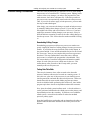
Synchronous and Asynchronous Program Scanning
One of the most important considerations when implementing a
backup system is the effect of divergence on the system. Divergence
occurs when the primary and secondary controllers are running their
applications and scanning the I/O asynchronously to each other. This
mode of operation can cause a condition where one of the controllers
is several program and I/O scans ahead of (or behind) the other.
Because of this condition, the logic in each controller could resolve
differently, thus creating differences (i.e., divergence) in the I/O and
data tables.
As divergence between the primary and secondary controllers
increases, the possibility of a bump in the process when a switchover
occurs also increases. This could be critical in some backup
applications.
Asynchronous program scanning allows both the primary and
secondary controllers to operate as fast as they possibly can, without
attempting to synchronize with each other. This mode of operation
should be used when the divergence of programs, I/O tables, and data
tables is not a critical consideration. Asynchronous program
scanning has no effect on program scan time. You should select this
mode of operation when the primary is programmed to run the normal
application, and the secondary is programmed to perform a different
task (e.g., a safety shutdown, a clean and wash operation, etc.).
Synchronous program scanning forces the primary and secondary
controllers to synchronize their program and I/O scanning. Both
controllers start their program scan at the same time, and both gather
input data at the same time. This mode of operation should be used
when minimizing the divergence of programs, I/O tables, and data
tables is a critical and necessary consideration. Synchronous program
scanning impacts program scan time in both controllers (i.e., scan
times will be longer), although this impact is not significant in most
cases.
You can change the operational mode from the Configure tab of the
ControlNet Hot Backup screen:.
Publication 1785-6.5.24 February 1999
3-14
Installing and Configuring Your ControlNet PLC-5 Backup System
Note: When you choose Synchronous mode, you will have to enter a
Maximum Program Scan Time as well. Before selecting
Synchronous mode, enter a value into the Max Program Scan Time
field. This value should be slightly larger than the maximum program
scan time recorded in the Processor Status file. (Refer to Appendix D
for more information on program synchronization.)
To change the operational mode, click on the Operational Mode box
and choose the mode you would like to use. (The default mode is
Asynchronous.)
Equivalence Checks
You can perform equivalence checking to verify that selected areas in
both the primary and secondary PLC processors are identical.
You can enable various equivalence checks from the Configuration
tab of the ControlNet Hot Backup screen. Simply check the boxes
corresponding to the equivalence checks you wish to enable.
Equivalence status is updated constantly on both PLC processors
while there is a qualified backup system. If there are differences
between the two processors, a status message appears, indicating the
difference(s), and warning you that the secondary will major fault
upon switching to Run mode. The Configure tab provides you with
the current status for each equivalence check; Equivalent indicates
that the two processors are identical, and Different indicates that there
were differences detected.
Publication 1785-6.5.24 February 1999
Installing and Configuring Your ControlNet PLC-5 Backup System
3-15
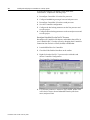
Crossloading
You can perform data table crossloading on demand. While both PLC
processors are running, you can initiate a crossload from either the
primary or secondary processor. You can perform a crossload on the
following data file types:
•
all timer accumulation values in the data table
•
all counter accumulation values in the data table
•
all PID files in the data table
•
user-defined files, which allow you to select up to 2 separate data
file numbers and/or a range of files.
You can set up and select the files to be crossloaded from the
Crossload tab of the ControlNet Hot Backup screen.
To crossload timer, counter, or PID values, simply click on the
respective button. The crossload is performed as soon as you click on
the appropriate button.
To set up user-defined crossloading, you must designate the files you
wish to be crossloaded. If you are selecting individual files, enter the
first file you wish to crossload in the First Selected File box. If you
wish to also crossload a second file, enter it in the Second Selected
File box.
If you wish to crossload a range of files, enter the lowest file number
and the highest file number in the respective boxes.
Once you have selected the files you wish to crossload, click on the
Crossload User Files button to perform the operation. Note that you
can perform a crossload for individual files and for a range of files
simultaneously.
Publication 1785-6.5.24 February 1999
3-16
Installing and Configuring Your ControlNet PLC-5 Backup System
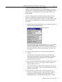
Status
You can view system status from the Status tab of the ControlNet Hot
Backup screen.
The CBC Module LEDs section mirrors the display of the LEDs on
the 1785-CHBM module which is currently online.
Diagnostic Counters
Diagnostic counters provide information on the number of times the
Maximum Program Scan has exceeded the Maximum Program Scan
Time configured for the system when in Synchronous mode. These
counters are incremented by 1 every time the actual program scan is
greater than the configured program scan. The Lost Partner counter
increments every time the system has detected a loss of
communication between the primary and secondary PLC processors.
You can press the Clear button to reset these values.
Qualification Error Reason
If the qualification of the system fails, the Qualification Error Reason
indicates the reason why the failure occurred. Refer to Chapter 4 for
information on corrective actions you can take.
Invalid State Reason
If the system is in an Invalid backup state (refer to Appendix B for
more information on backup states), a description of the problem is
displayed. Refer to chapter 4 for information on corrective actions
you can take.
Maximum Pscan Information
This information is applicable for Synchronous mode operation only.
The following parameters are listed in this section:
•
•
•
•
Publication 1785-6.5.24 February 1999
Configured Scan - the Maximum Program Scan Time
Adjusted Scan - the Maximum Program Scan Time rounded up to
the next integer multiple of the NUT
NUT Time (ms) - the parameter configured in RSNetWorx
Number of NUTs - the number of NUTs in the Adjusted
Maximum Program Scan Time
Installing and Configuring Your ControlNet PLC-5 Backup System
Processor Editing Considerations
3-17
There are some considerations you should be aware of when editing
the processor of a ControlNet PLC-5 backup system. Editing, in this
context, refers to any changes you make to the program files, data
table structure, force tables, and status file. Edits that you make to
one processor are not automatically transferred to the other processor.
Thus, if you wish for edits to apply to both processors, you must take
the steps to make that happen.
Most simply, you can ensure the changes are made to both processors
by manually making those changes yourself. If your edits are small,
this might be the fastest and easiest solution. However, if you have
made large amounts of editing changes to one processor, it may be
difficult and time consuming to make all the same editing changes to
the other processor. This section describes another method for doing
so.
Downloading Editing Changes
Downloading a program saved from one processor to another can
greatly simplify the transfer of editing changes from one processor to
another. If you follow the steps described earlier in this chapter, in
the section entitled “Create and Download the Project for the Second
PLC Processor,” then you can complete this processor-to-processor
download. The steps outlined there ensure that a new, different
project name is created for the program that is downloaded. They
also ensure that the ControlNet configuration information remains
unique for each of the processors, which must be the case. This
means that any edits you make to the I/O map table, you must
manually make on each processor.
Testing Data Table Edits
There may be instances where edits are made to the data table
structure, and these edits need to be tested on a running system. If
this is the case, place one of the processors in your backup system
into Program mode, and make the edits to that processor. Make sure
that the data table structure and the ladder program equivalence
checks are disabled while performing edit switchovers, since ladder
program equivalence checks are dependent on data table structures.
Next, place the edited system into Run mode. A forced switchover
can be performed, which makes the edited processor the primary, and
the unedited processor the secondary. If problems occur within the
edited system, a second forced switchover makes the unedited
processor primary again.
Note that Qualification crossloading and on-demand crossloading are
disabled when the data table structures between the processors are
different.
Publication 1785-6.5.24 February 1999
3-18
Installing and Configuring Your ControlNet PLC-5 Backup System
Publication 1785-6.5.24 February 1999
Chapter
4
Monitoring and Troubleshooting Your
ControlNet PLC-5 Backup System
Chapter Objectives
7KLVFKDSWHUGHVFULEHVWKHGLDJQRVWLFFDSDELOLWLHVRIWKH&RQWURO1HW
3/&EDFNXSV\VWHPDQGSURYLGHV\RXZLWKWLSVWRKHOS\RXLQ
WURXEOHVKRRWLQJGLIILFXOWLHVZLWK\RXUV\VWHP
7KH3/&&RQWURO1HWEDFNXSV\VWHPJHQHUDWHVGLDJQRVWLF
LQIRUPDWLRQWRDVVLVW\RXZLWKWURXEOHVKRRWLQJSUREOHPVWKDWPD\
DULVHZLWKLQDEDFNXSDSSOLFDWLRQ0RVWRIWKHGLDJQRVWLFLQIRUPDWLRQ
LVVWRUHGZLWKLQWKH&RQWURO1HW%DFNXS&RQILJXUDWLRQDQG6WDWXVILOH
2WKHU&RQWURO1HWEDFNXSGLDJQRVWLFLQIRUPDWLRQLVVWRUHGLQWKH
0DMRU)DXOW&RGHZRUGRIWKH6WDWXV)LOH6DQGRQWKH/('VRI
WKH&+%0&RQWURO1HWEDFNXSFDUWULGJH
<RXFDQDFFHVVWKH&RQWURO1HW%DFNXS&RQILJXUDWLRQDQG6WDWXVILOH
GLUHFWO\YLDODGGHUORJLFDQGWKHGDWDPRQLWRURULQGLUHFWO\YLDWKH+RW
%DFNXSXWLOLW\ZLWKLQ56/RJL[7KHVHFWLRQVLQWKLVFKDSWHUUHIHU
RQO\WRGLUHFWDFFHVVWRWKH&RQWURO1HW%DFNXS&RQILJXUDWLRQDQG
6WDWXVILOHWKRXJKZHUHFRPPHQGSHUIRUPLQJWKHVDPHRSHUDWLRQYLD
WKH+RW%DFNXSXWLOLW\ZKHQHYHUSRVVLEOH
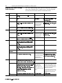
ControlNet PLC-5 Backup-Specific
Major Fault Error Codes
7KH3/&SURFHVVRUVWRUHVPDMRUIDXOWFRGHVLQZRUGRIWKH
SURFHVVRUVWDWXVILOH67KHIROORZLQJWDEOHOLVWVQHZPDMRUIDXOW
FRGHVVSHFLILFWRWKH&RQWURO1HW+RW%DFNXSSURFHVVRUDQGWKH
VXJJHVWHGFRUUHFWLYHDFWLRQIRUHDFK
If you see fault code:
Which indicates this fault:
230
System attempted transition to Run mode with processor Change from the Invalid backup state to the No Control backup
in Invalid backup state.
state before transitioning into Run mode. Refer to the Invalid
backup state troubleshooting table later in this chapter.
Bypassed qualification (may occur during race condition Transition the PLC-5 processors into Run mode one at a time.
when both processors attempt to go into Run mode at the
same time).
Both processors attempted to be primaries.
Check all media for broken cables, loose connectors, missing
terminators, etc..
ControlNet configuration invalid on transition into Run
Reconfigure the ControlNet channel.
mode.
Failed Qualification.
Refer to the qualification major faults troubleshooting table later
in this chapter.
231
232
233
234
Take this corrective action:
$77(17,217KHSURFHVVRUGRHVQRWLQYRNHWKHIDXOWURXWLQHIRU
DQ\RIWKHQHZIDXOWFRGHVIRUWKH&RQWURO1HW3/&EDFNXSV\VWHP
VLQFHWKH\DUHQRQUHFRYHUDEOHIDXOWV
3XEOLFDWLRQ)HEUXDU\
4-2
Monitoring and Troubleshooting Your ControlNet PLC-5 Backup System
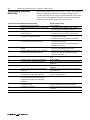
Using the 1785-CHBM Cartridge
Status Indicators
7KH&+%0FDUWULGJHVWDWXVLQGLFDWRUVLQGLFDWHWKHRSHUDWLRQDO
VWDWHRIWKH&RQWURO1HW3/&EDFNXSV\VWHP7KHIROORZLQJWDEOH
OLVWVWKHYDULRXV/('VWDWHVDQGWKHUHFRPPHQGHGDFWLRQ:
/('
&RORU
,QGLFDWHV
3UREDEOH&DXVH
&RUUHFWLYH$FWLRQ
35,
*UHHQ
7KLVSURFHVVRULVWKHSULPDU\LHLWFRQWUROVWKH
1RUPDORSHUDWLRQ
1RDFWLRQUHTXLUHG
7KLVSURFHVVRULVLQWKH/RQHO\3ULPDU\EDFNXS
1RJRRGVFKHGXOHG
&KHFNPHGLDIRUEURNHQFDEOHV
VWDWH
FRQQHFWLRQV
ORRVHFRQQHFWRUVPLVVLQJ
RXWSXWV
*UHHQEOLQNLQJ
WHUPLQDWRUVHWF
5HG
7KHEDFNXSV\VWHPLVQRW\HWFRPSOHWHO\
FRQILJXUHGLHV\VWHPLVLQWKH,QYDOLGEDFNXS
VWDWH
2II
7KLVSURFHVVRULVQRWWKHSULPDU\LHV\VWHPLV
•Improper backup
configuration parameters
•Improper ControlNet
Backup Integer file
5HIHUWR7URXEOHVKRRWLQJWKH
,QYDOLG%DFNXS6WDWHVHFWLRQODWHU
LQWKLVFKDSWHU
1RUPDORSHUDWLRQ
1RDFWLRQUHTXLUHG
1RUPDORSHUDWLRQ
1RDFWLRQUHTXLUHG
•Improper backup
configuration parameters
5HIHUWR7URXEOHVKRRWLQJWKH
LQWKH1R&RQWURORU6HFRQGDU\EDFNXSVWDWH
6(&
<HOORZ
7KLVSURFHVVRULVWKHTXDOLILHGVHFRQGDU\LH
V\VWHPLVLQWKH6HFRQGDU\EDFNXSVWDWH
5HG
7KHEDFNXSV\VWHPLVQRW\HWFRPSOHWHO\
FRQILJXUHGLHV\VWHPLVLQWKH,QYDOLGEDFNXS
VWDWH
2II
7KLVSURFHVVRULVQRWWKHVHFRQGDU\LHV\VWHP
•Improper ControlNet
Backup Integer file
,QYDOLG%DFNXS6WDWHVHFWLRQODWHU
LQWKLVFKDSWHU
1RUPDORSHUDWLRQ
1RDFWLRQUHTXLUHG
1RUPDORSHUDWLRQ
1RDFWLRQUHTXLUHG
1RUPDORSHUDWLRQ
1RDFWLRQUHTXLUHG
4XDOLILFDWLRQDFWLYH
1RUPDORSHUDWLRQ
1RDFWLRQUHTXLUHG
7KHSULPDU\DQGVHFRQGDU\SURFHVVRUVDUHQRW
•Standalone processor
9HULI\WKDWWKHFRQQHFWLRQ
LVLQWKH1R&RQWURORU3ULPDU\EDFNXSVWDWH
48$/
*UHHQ
7KHV\VWHPKDVERWKDSULPDU\DQGDVHFRQGDU\
SURFHVVRUZKLFKDUHFRPPXQLFDWLQJSURSHUO\
ZLWKHDFKRWKHUWKHVHFRQGDU\SURFHVVRULV
TXDOLILHG
<HOORZ
7KHV\VWHPKDVERWKDSULPDU\DQGDVHFRQGDU\
SURFHVVRUZKLFKDUHFRPPXQLFDWLQJSURSHUO\
ZLWKHDFKRWKHUEXWWKHVHFRQGDU\LVQRW\HW
TXDOLILHG
$OWHUQDWLQJ\HOORZ
DQGJUHHQ
2II
FRPPXQLFDWLQJSURSHUO\ZLWKHDFKRWKHU
•One or both processors are
in the Invalid backup state
SDUDPHWHUVZRUGVRIWKH
&RQWURO1HW%DFNXS,QWHJHUILOHDUH
WKHVDPHIRUERWKSURFHVVRUV
•Improper backup
configuration parameters
6<1&
*UHHQ
7KHV\VWHPLVRSHUDWLQJLQV\QFKURQRXVPRGH
1RUPDORSHUDWLRQ
1RDFWLRQUHTXLUHG
•Maximum Program Scan
Time configuration
parameter too small
•Clear the Maximum Program Scan
Exceeded counter by writing a non-zero
value into the clear diagnostics counters
word (word 32) of the ControlNet Backup
Configuration and Status file.
DQGWKLVSURFHVVRUKDVQHYHUH[FHHGHGWKH
DGMXVWHGPD[LPXPSURJUDPVFDQWLPHSDUDPHWHU
5HG
7KHV\VWHPLVRSHUDWLQJLQV\QFKURQRXVPRGH
DQGWKLVSURFHVVRUKDVEHHQRXWRIV\QFLHLWV
DFWXDOSURJUDPVFDQWLPHKDVH[FHHGHGWKH
DGMXVWHGPD[LPXPSURJUDPVFDQWLPH
SDUDPHWHU:KLOHWKHRXWRIV\QFFRQGLWLRQPD\
KDYHEHHQWHPSRUDU\WKLV/('UHPDLQV
•Spike in program scan
time, possibly due to online
editing
LOOXPLQDWHGWRLQGLFDWHWKDWDQRXWRIV\QF
FRQGLWLRQKDVRFFXUUHG
2II
7KHV\VWHPLVRSHUDWLQJLQ$V\QFKURQRXVPRGH
3XEOLFDWLRQ)HEUXDU\
1RUPDORSHUDWLRQ
•Increase Maximum Program Scan Time
configuration parameter (word 14) of the
ControlNet Backup Configuration and
Status file.
1RDFWLRQUHTXLUHG
Monitoring and Troubleshooting Your ControlNet PLC-5 Backup System
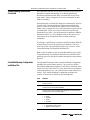
Troubleshooting the Invalid
Backup State
4-3
7KH,QYDOLG%DFNXSVWDWHLVLQGLFDWHGZKHQERWKWKH35,DQG6(&
/('VDUHUHG7KHILUVWWKLQJWRFKHFNLVWKDW\RXKDYHFUHDWHGWKH
&RQWURO1HW%DFNXS&RQILJXUDWLRQDQG6WDWXVILOHDQGWKDWWKHILOH
QXPEHURIWKLVILOHLVSODFHGLQWRWKHSURFHVVRUVWDWXVILOHZRUG6
7KLVILOHPXVWEHDQ,QWHJHUILOHILOHW\SH1DQGPXVWEHH[DFWO\
ZRUGVLQOHQJWK
7KH&RQWURO1HW%DFNXS&RQILJXUDWLRQDQG6WDWXVILOHFRQWDLQVD
GLDJQRVWLFZRUGZRUGWKDWLQGLFDWHVWKHUHDVRQIRUWKH,QYDOLG
EDFNXSVWDWH7KHIROORZLQJWDEOHOLVWVWKHYDULRXV,QYDOLGEDFNXS
VWDWHUHDVRQFRGHVDQGVXJJHVWHGFRUUHFWLYHDFWLRQ
If you see reason code: Which indicates this condition:
0
1
2
3
4
5
6
Take this corrective action:
Valid backup state
No action required
Receive handshake connection not found in I/O Map Table • Configure the handshake connections in the I/O map table.
• Enter the handshake connection numbers in words 1 and 2
of the ControlNet Backup Configuration and Status file.
•
Configure the handshake connections in the I/O map table.
Send handshake connection not found in I/O map table
• Enter the handshake connection numbers in words 1 and 2
of the ControlNet Backup Configuration and Status file.
Receive handshake connection wrong size
Make the handshake connection in the I/O map table 5 words
long.
Send handshake connection wrong size
Make the handshake connection in the I/O map table 5 words
long.
Node address number wrong
Enter the odd node number of the odd-even backup pair into
word 0 of the ControlNet Backup Configuration and Status file.
Operation mode word invalid
Enter a valid operation mode value into word 10 of the
ControlNet Backup Configuration and Status file.
7
Equivalence mode word invalid
8
Designated Primary word invalid
9
Maximum Program Scan Time word invalid
11
Handshake Requested Packet Interval (RPI) invalid
12
Crossload file number parameters invalid
13
ControlNet NUT not established. Until the processor is
attached to the ControlNet channel, the NUT is unknown.
0 = asynchronous
1 = synchronous
Enter a valid equivalence mode word (i.e., 0 - 63) into word 11
of the ControlNet Backup Configuration and Status file.
Enter a valid Designated Primary word into word 12 of the
ControlNet Backup Configuration and Status file.
0 = inactive
1 = active
Enter a valid Maximum Program Scan Time word (i.e., less than
or equal to 128*NUT) into word 13 of the ControlNet Backup
Configuration and Status file.
Make the handshake connection’s RPI in the I/O map table at
least one NUT, but less than 2 NUTs.
• Enter valid file numbers (0 - 999) into words 55 through 58
of the ControlNet Backup Configuration and Status file
• Make sure the crossload range low word (word 57) value is
less than or equal to the crossload range high word (word
58) value.
Attach the processor to the ControlNet channel.
3XEOLFDWLRQ)HEUXDU\
4-4
Monitoring and Troubleshooting Your ControlNet PLC-5 Backup System
Troubleshooting Qualification
Major Faults
:KHQDTXDOLILFDWLRQPDMRUIDXOWRFFXUV6 WKH&RQWURO1HW
%DFNXS&RQILJXUDWLRQDQG6WDWXVILOHFRQWDLQVDGLDJQRVWLFZRUG
ZRUGWKDWLQGLFDWHVWKHUHDVRQZK\WKHTXDOLILFDWLRQPDMRUIDXOW
RFFXUUHG7KHIROORZLQJWDEOHOLVWVWKHYDULRXVTXDOLILFDWLRQPDMRU
IDXOWUHDVRQFRGHVDQGWKHVXJJHVWHGFRUUHFWLYHDFWLRQ
If you see reason code: Which indicates this condition:
0
1
2
3
4
5
6
8
9
10
11
12
13
14
15
17
18
Qualification successfully completed
Failed Qualification Equivalence check - Ladder programs
different
Failed Qualification Equivalence check - Data Table
Structures different
Failed Qualification Equivalence check - Redundant
connections in I/O Map Tables different
Take this corrective action:
No action required
• Disable ladder program equivalence check, if desired.
• Make ladder programs identical in each processor.
• Disable data table structure equivalence check, if desired.
• Make data table structures identical in each processor.
• Disable Redundant Connections in I/O Map Table
equivalence check, if desired.
• Make redundant connections identical in each processor.
Failed Qualification Equivalence check - ControlNet Hot
• Disable ControlNet Hot Backup file connection parameters
Backup file connection parameters different
equivalence check, if desired.
• Make ControlNet Hot Backup file connection parameters
identical in each processor.
Failed Qualification Equivalence check - Force Tables
• Disable Force Tables equivalence check, if desired.
different
• Make Force Tables identical in each processor.
Failed Qualification Equivalence check - Configuration
• Disable processor status file equivalence check, if desired
parameters in processor status file different
• Make processor status file configuration parameters
identical in each processor
Processor major faulted during qualification
Fix the reason for the major fault. Refer to S:12 for major fault
codes
Keyswitch changed to Program during qualification
No action required
Files being created or deleted during qualification
Refrain from editing the data table file or program files during
qualification.
Upload or Download in progress during qualification
Refrain from uploading or downloading to the processor during
qualification.
ControlNet channel reconfiguration in progress during
Refrain from performing a ControlNet channel reconfiguration
qualification
during qualification.
The processor changed from the No Control backup state Refrain from modifying the ControlNet backup configuration
to the Invalid backup state during qualification
parameters during qualification.
The partner processor was in the Primary backup state
Clear the fault and go back into Run mode.
when qualification started. The partner processor
changed out of the Primary backup state during
qualification.
The partner’s ControlNet Hot Backup configuration
Refrain from changing the partner processor’s ControlNet Hot
parameters are invalid
Backup configuration parameters during qualification.
Qualification crossload failed
Refer to the Troubleshooting Qualification Crossloads section in
this chapter.
Edits in progress during qualification
Refrain from editing during qualification.
3XEOLFDWLRQ)HEUXDU\
Monitoring and Troubleshooting Your ControlNet PLC-5 Backup System
Troubleshooting Qualification
Crossloads
4-5
,IWKHGDWDWDEOHVWUXFWXUHVDUHWKHVDPHEHWZHHQWKHWZRSURFHVVRUV
GDWDWDEOHFURVVORDGVDXWRPDWLFDOO\RFFXUGXULQJTXDOLILFDWLRQ
6KRXOGWKH4XDOLILFDWLRQ'DWD7DEOHFURVVORDGVIDLOWKHSURFHVVRU
PDMRUIDXOWV5HIHUWR$SSHQGL[&IRUPRUHLQIRUPDWLRQRQGDWD
WDEOHFURVVORDGLQJ
:KHQDGDWDWDEOHFURVVORDGIDLOVGLDJQRVWLFLQIRUPDWLRQLVVWRUHGLQ
ZRUGVRIWKH&RQWURO1HW%DFNXS&RQILJXUDWLRQDQG6WDWXVILOH
:RUGRIWKLVILOHFRQWDLQVWKHILOHQXPEHURIWKHFURVVORDGWKDW
IDLOHGZRUGFRQWDLQVWKHHUURUFRGHLQGLFDWLQJWKHUHDVRQZK\WKH
FURVVORDGIDLOHG7KHVHHUURUFRGHVDUHLGHQWLFDOWRWKH0HVVDJH
,QVWUXFWLRQ(UURU&RGHV6HHWKH,QVWUXFWLRQ6HW5HIHUHQFH0DQXDO
3XEOLFDWLRQIRUDFRPSOHWHOLVWLQJRIWKHYDULRXVHUURU
FRGHVZKLFKFDQEHHQFRXQWHUHGZKLOHH[HFXWLQJD0HVVDJH
,QVWUXFWLRQ
)RUH[DPSOHDTXDOLILFDWLRQFURVVORDGFRXOGIDLOLIWKH'DWD7DEOHILOH
RQWKHSULPDU\SURFHVVRUKDVUHDGSULYLOHJHVGLVDEOHG7KLVHUURU
VKRZVXSDVHUURUFRGH[)%SULYLOHJHHUURULQZRUGRIWKH
&RQWURO1HW%DFNXS&RQILJXUDWLRQDQG6WDWXVILOH
1RWH,IWKHILOHQXPEHURIWKHFURVVORDGWKDWIDLOHGZRUGRIWKH
&RQWURO1HW%DFNXS&RQILJXUDWLRQDQG6WDWXVILOHLV[))))RQWKH
TXDOLI\LQJSURFHVVRUWKHQWKHILOHQXPEHUWKDWIDLOHGLVRQWKHSULPDU\
SURFHVVRU
ControlNet Backup Configuration
and Status File
7KHGDWDWDEOHILOHQXPEHURIWKH&RQWURO1HW%DFNXS&RQILJXUDWLRQ
DQG6WDWXVILOHFDQEHIRXQGLQWKH3/&SURFHVVRUDWZRUG6
7KHGHIDXOWFRQILJXUDWLRQSDUDPHWHUVLQWKLVILOHDUHLQLWLDOL]HGZKHQ
WKHILOHH[LVWVWKHYDOXHLQ6LVFRUUHFWDQGDWOHDVWRQHRIWKHWKUHH
FRQQHFWLRQSDUDPHWHUVLHRQHRIWKHILUVWWKUHHZRUGVRIWKHILOHLV
LQYDOLG7KH&RQWURO1HW%DFNXS&RQILJXUDWLRQDQG6WDWXVILOH
FRQVLVWVRIZRUGVDVGHILQHGLQWKHIROORZLQJWDEOH
Word
Definition
0
Odd node address of the odd/even pair of node addresses for the two PLC-5
backup processors.
1
Message number of the scheduled Backup Handshake connection being sent
from the processor at the Odd node address.
2
Message number of the scheduled Backup Handshake connection being sent
from the processor at the Even node address.
3
Backup state of the processor. Valid values include:
• 0 - Invalid
• 1 - No Control
• 2 - Primary
• 4 - Secondary
4
Qualification state of the system. Valid values include:
• 0 - No qualified secondary present
• 1 - Qualified secondary present
3XEOLFDWLRQ)HEUXDU\
4-6
Monitoring and Troubleshooting Your ControlNet PLC-5 Backup System
3XEOLFDWLRQ)HEUXDU\
Word
Definition
5
Reason code indicating why the processor is in the Invalid backup state. This
word is constantly updated until the processor is no longer in this state. Valid
values include:
• 0 - In valid state
• 1 - Receive handshake connection not found in I/O map table
• 2 - Send handshake connection not found in I/O map table
• 3 - Receive handshake connection wrong size
• 4 - Send handshake connection wrong size
• 5 - node address number wrong
• 6 - Operation mode word invalid
• 7 - Equivalence mode word invalid
• 8 - Designated Primary word invalid
• 9 - Max Program Scan Time word invalid
• 11 - Handshake is not 1 NUT
• 12 - Crossload parameters invalid
• 13 - NUT not established
6
This is a checksum of the first 3 words of this file. If the checksum is not valid,
the firmware will continuously write default values for the configuration
parameters in this file.
7
Partner present. This word is constantly updated by the PLC-5 processor,
indicating whether a partner processor is handshaking with the current
processor. This word is updated only when the processor is in a valid backup
state (i.e., No Control, Secondary, or Primary). Valid values include:
• 0 - No partner found
• 1 - Partner PLC-5 handshaking with this PLC-5
8
Output Ownership Invalid Count word. This word indicates how many
connections are not owned by this processor (Primary backup state only). This
value is -1 when the processor is in the Secondary backup state.
9
Lonely Primary Backup State Counter. This counter is incremented every time
this processor goes into the Lonely Primary backup state.
10
Operational mode of the system. Valid values include:
• 0 - Asynchronous (default)
• 1 - Synchronous
11
Equivalence checks; there are 6 bits defined (i.e., one bit per equivalence
check). If a bit is set, the corresponding equivalence check will be performed.
If the bit is not set, no check is performed. By default, all equivalence checking
is enabled. The remaining 10 bits in the word must be set to 0.
• Bit 0 - Ladder Logic equivalence check
• Bit 1 - Data Table Structure equivalence check
• Bit 2 - I/O Map Table equivalence check
• Bit 3 - Backup Configuration and Status file equivalence check
• Bit 4 - Force Table equivalence check
• Bit 5 - Status file equivalence check
12
Designated Primary. Valid values are:
• 0 - No Designated Primary (default)
• 1 - The PLC-5 processor with the odd node address is the Designated
Primary
13
Qualification Delay. This is the amount of time (in ms) to delay the secondary in
Run mode before becoming qualified. The default value is 0.
14
Maximum Program Scan Time (Synchronous mode only); the amount of time (in
ms) for the largest program scan. This value cannot be greater than 127 times
the NUT value.
Monitoring and Troubleshooting Your ControlNet PLC-5 Backup System
4-7
Word
Definition
15-19
reserved
20-24
These words are functionally the same as words 10 through 14. The difference
is that words 20 through 24 display the current internal PLC-5 processor state
of these configuration parameters. When in Run mode, the PLC-5 processor
will continuously update words 20 through 24. In other words, the software
tool will write the configuration parameters into words 10 through 14, while the
PLC-5 processor will write its internal PLC-5 processor state of these
configuration parameters into words 20 through 24. When you accept
configuration changes, the configuration parameters in words 10 through 14
are copied into words 20 through 24.
25
Adjusted Maximum Program Scan Time. This word is the Maximum Program
Scan Time parameter, rounded up to the next integer multiple of the NUT value.
This word is written by the PLC-5 processor, and is continuously updated while
the processor is in Run mode.
26
The number of NUTs per Maximum Program Scan Time. This word is the
number of NUTs in the Adjusted Maximum Program Scan Time. This word is
written by the PLC-5 processor, and is continuously updated while the
processor is in Run mode.
27
The NUT time, in 10 microsecond units, is continuously written here while the
processor is in Run mode.
28
Configuration status. This word gives either the reason why the configuration
attempt was unsuccessful, or whether the configuration parameters were
overwritten because the system went into Run mode as a secondary system.
• 6 - Operation mode word invalid
• 7 - Equivalence Check word invalid
• 8 - Designated Primary word invalid
• 9 - Max Program Scan Time word invalid
• 10 - Configuration parameters were overwritten by the primary system
• 12 - Crossload parameter invalid
29
reserved
30
Accept Configuration Changes. A non-zero value written into this location
forces the primary PLC-5 processor to accept the new configuration
parameters. After the PLC-5 processor has done so, it will zero this word. This
command is only in effect for the primary processor. The configuration
parameters you change are:
• Operational mode
• Maximum Program scan time
• Equivalence checks
• Designated primary
• Crossload parameters
31
Force Switchover. A non-zero value written into this location forces the primary
processor to switch over control to a secondary processor. After the processor
has read the non-zero value, the PLC-5 processor will zero this word. This
command works for both the primary and secondary processors. However, if
there is a Designated Primary, this command will not function.
32
Clear Diagnostic Counters. A non-zero value written into this location clears the
maximum program scan exceed counter, the lost partner counter, and the
lonely primary backup state counter. After the processor has read the non-zero
value, it will clear this word. This feature works for both the primary and
secondary processors, but will only work in Run mode.
3XEOLFDWLRQ)HEUXDU\
4-8
Monitoring and Troubleshooting Your ControlNet PLC-5 Backup System
3XEOLFDWLRQ)HEUXDU\
Word
Definition
33
Perform On-Demand Crossload. You can specify whether to crossload timers,
counters, PID files, or user-defined files (configured in words 55, 56, 57, and 58
of the ControlNet Backup Configuration and Status file) by setting appropriate
bits in this word. After the PLC-5 has read the word, it clears it. This feature
works for both primary and secondary processors.
• Bit 0 - Crossload Timers
• Bit 1 - Crossload Counters
• Bit 2 - Crossload PID
• Bit 3 - Crossload user-defined files
34-39
reserved
40-45
The timedate stamp indicating when the processor last took over as the primary
is stored here. The format of the data is the same as the clock in the status file.
46
Qualification status. The reason code for why the processor failed qualification
or if the configuration parameters were changed by the primary. Valid values
include:
• 0 - Passed qualification
• 1 - Equivalence check - Ladder programs different
• 2 - Equivalence check - Data table structures different
• 3 - Equivalence check - I/O map tables different
• 4 - Equivalence check - ControlNet Backup Configuration and Status files
different
• 5 - Equivalence check - Force tables different
• 6 - Equivalence check - Status files different
• 7 - Qualification passed, but configuration parameters changed by primary
• 8 - Qualification failed due to processor being faulted
• 9 - Qualification failed due to keyswitch change to Program mode
• 10 - Qualification failed due to Run mode inhibited
• 11 - Qualification failed due to processor uploading or downloading program
• 12 - Qualification failed due to ContronNet reconfiguration in progress
• 13 - Qualification failed due to invalid backup state
• 14 - Qualification failed due to partner no longer being a primary
• 15 - Qualification failed due to invalid backup configuration parameters
• 16 - unused
• 17 - Qualification crossload failed
• 18 - Qualification failed due to unavailable edit resource
47
Lost Partner Counter. A counter which increments every time you lose
communication with the partner processor.
48
Maximum Program Scan Exceed Counter. A counter which increments every
time the maximum program scan time is exceeded. This counter is reset for
the processor on transition into Run mode.
49
Equivalence Check Error. A bit is set for each area in which an equivalence
mismatch is detected. There is a background check of the ladder program,
force tables, and status files for differences.
• Bit 0 - Set if the ladder programs between the two systems are different
• Bit 1 - Set if the data table structures between the two systems are
different. Note the data table structure is not the same as the values in the
data table files.
• Bit 2 - Set if the I/O map tables between the two systems are different
• Bit 3 - Set if the Backup Configuration and Status files between the two
systems are different
• Bit 4 - Set if the Force tables between the two systems are different
• Bit 5 - Set if the Status files between the two systems are different
Monitoring and Troubleshooting Your ControlNet PLC-5 Backup System
4-9
Word
Definition
50
Qualification Crossload Time. The time (in ms) it takes to crossload the entire
data table from the primary processor to the secondary processor. This value is
overwritten each time the processor goes through qualification.
51
On-Demand Crossload Time. The time (in ms) it takes to crossload the data
table state information from the primary to the secondary. This value is
overwritten each time the processor goes through qualification, and when you
initiate an On-Demand Data Table Crossload command.
52
Crossload Active. This word equals 1 when a crossload is active; it is equal to 0
when a crossload is not active. This word applies to both Qualification and
On-Demand crossloads.
53
Crossload Status. This is a Message instruction error code. The processor
writes the value into this word. For information on error descriptions, refer to
your PLC-5 Instruction Set Reference Manual.
54
Crossload Failed File. This word displays the file number on which the
crossload failed. The crossload status word located in word 53 displays the
error code and word 54 displays its correlated file.
55
User-Defined Crossload File 1. You can select a single file number, written in
this word, to be crossloaded during the Qualification crossload, and on-demand
when setting the appropriate bit in word 33.
56
User-Defined Crossload File 2. You can select a single file number, written in
this word, to be crossloaded during the Qualification crossload, and on-demand
when setting the appropriate bit in word 33.
57
User-Defined Crossload Range Low File. You can select a range of files to be
crossloaded during the Qualification crossload, and on demand when setting
the appropriate bit in word 33. The lower file number of the range of files to be
crossloaded must be written into this register.
58
User-Defined Crossload Range High File. You can select a range of files to be
crossloaded during the Qualification crossload, and on demand when setting
the appropriate bit in word 33. The higher file number of the range of files to be
crossloaded must be written into this register.
59-64
The secondary time/date stamp of when the processor last took over as
secondary processor. The format of the date is the same as the system clock in
the status file.
65-68
These words are functionally the same as words 55 through 58. The difference
is that these words display the current PLC-5 processor state of these
configuration parameters. When in Run mode, the processor continuously
updates words 65 through 68. In other words, new configuration parameters
are written into words 55 through 58, while the PLC-5 processor writes its
internal state of these configuration parameters into words 65 through 68.
When you accept a configuration, the configuration parameters in words 55
through 58 are copied into words 65 through 68.
69-199
reserved
,PSRUWDQW'RQRWDOWHUDQ\UHVHUYHGZRUGV9DOXHVLQWKHVHZRUGV
PD\EHFKDQJHGRUXVHGE\WKH3/&SURFHVVRUGXULQJQRUPDO
RSHUDWLRQ
3XEOLFDWLRQ)HEUXDU\
4-10
Monitoring and Troubleshooting Your ControlNet PLC-5 Backup System
3XEOLFDWLRQ)HEUXDU\
Appendix
A
Specifications
Specifications
7KHIROORZLQJVSHFLILFDWLRQVDUHIRUWKH&+%0FDUWULGJH
Description:
Value:
Memory Module
1785-CHBM
Capacity
100K words
Type
Nonvolatile
Write Protection
By removing the jumper
Weight
70.875g
2.5 oz.
Environment
Shock Testing
Operating Temperature
0° to 60° C (32° to 140° F)
Storage Temperature
-40° to 85° C (-40° to 185° F)
Relative Humidity
5% to 95% (without condensation)
Operating
15 g peak acceleration at 11 ms duration
Non-operating
3 g peak acceleration at 11 ms duration
Vibration Testing
2 g peak acceleration at 10-500 Hz
Agency Certification
•
•
•
•
CSA certified
CSA Class I, Division 2
Groups A, B, C, D
UL listed
CE marked for all applicable
directives
3XEOLFDWLRQ)HEUXDU\
A-2
Specifications
3XEOLFDWLRQ)HEUXDU\
Appendix
B
Backup States
7KLV$SSHQGL[GHVFULEHVWKHSRVVLEOHEDFNXSVWDWHVDQGEDFNXSVWDWH
WUDQVLWLRQVRIWKH3/&&RQWURO1HWEDFNXSV\VWHP7KHUHDUHIRXU
PDLQEDFNXSVWDWHV
Chapter Objectives
•
,QYDOLG
1R&RQWURO
3ULPDU\DQG/RQHO\3ULPDU\
Secondary
32:(583
12%$&.83
&$5'
,19$/,'
121B%$&.83
67$7(
,19$/,'
%$&.83
&21),*85$7,21
9$/,'
%$&.83
&21),*85$7,21
12
&21752/
67$7(
35,0$5<)281'
67$1'$/21(
48$/,),&$7,213$66('
,158102'(
,158102'(
127,1
127,1
58102'(
58102'(
35,0$5<
6(&21'$5<
67$7(
67$7(
6:,7&+29(5
%$&.8367$7(',$*5$0
3XEOLFDWLRQ)HEUXDU\
B-2
Backup States
,QYDOLG%DFNXS6WDWH
:KHQDQLPSURSHUEDFNXSFRQILJXUDWLRQH[LVWVWKH3/&
&RQWURO1HWEDFNXSV\VWHPJRHVLQWRWKH,QYDOLGEDFNXSVWDWH%RWK
WKH3ULPDU\DQG6HFRQGDU\/('VRQWKH&+%0FDUWULGJHDUH
VROLGUHGZKHQWKHV\VWHPLVLQWKLVVWDWHDQGWKH4XDOLILHGDQG
6\QFKURQRXV/('VDUHRII,I\RXVZLWFKWKHV\VWHPWR5XQPRGH
ZKLOHLQWKH,QYDOLGEDFNXSVWDWHDPDMRUIDXOWRFFXUV5HIHUWR
&KDSWHUIRUGHILQLWLRQVRIWKHPDMRUIDXOWFRGHV
7KHEDFNXSV\VWHPHQWHUVWKH,QYDOLGEDFNXSVWDWHZKHQRQHRUPRUH
RIWKHVHFRQGLWLRQVH[LVWV
WKHZRUG&RQWURO1HW%DFNXS&RQILJXUDWLRQDQG6WDWXV)LOH
GRHVQRWH[LVW
WKH&RQWURO1HW%DFNXS&RQILJXUDWLRQDQG6WDWXV)LOHH[LVWVEXW
LVWKHZURQJVL]HWKLVILOHPXVWEHH[DFWO\ZRUGVLQOHQJWK
WKHILOHQXPEHULQGH[WRWKH&RQWURO1HW%DFNXS&RQILJXUDWLRQ
DQG6WDWXV)LOHLQ6LVLQFRUUHFW
WKH&RQWURO1HWSHHUWRSHHUEDFNXSFRQQHFWLRQVFRQILJXUHGLQ
561HW:RU[GRQRWH[LVWRUDUHQRWFRUUHFWWKHVHFRQQHFWLRQV
PXVW
3XEOLFDWLRQ)HEUXDU\
EHVHQWWRDQGUHFHLYHGIURPWKHSDUWQHUSURFHVVRU
EHZRUGVORQJ
KDYHDQDFWXDOSDFNHWLQWHUYDOUDWHHTXDOWRRQH187
WKHILUVWZRUGVRIWKH&RQWURO1HW%DFNXS&RQILJXUDWLRQDQG
6WDWXV)LOHDUHLQFRUUHFWO\FRQILJXUHG
:RUG
9DOLG&RQILJXUDWLRQ
PXVWHTXDOWKHRGGQRGHQXPEHURIWKHRGGHYHQ3/&
SURFHVVRUSDLU
PXVWHTXDOWKHPHVVDJHQXPEHURIWKH&RQWURO1HWVFKHGXOHG
SHHUWRSHHUEDFNXSFRQQHFWLRQJRLQJIURPWKHRGGQRGH
QXPEHUWRWKHHYHQQRGHQXPEHURIWKHRGGHYHQ3/&
SURFHVVRUSDLU
PXVWHTXDOWKHPHVVDJHQXPEHURIWKH&RQWURO1HWVFKHGXOHG
SHHUWRSHHUEDFNXSFRQQHFWLRQJRLQJIURPWKHHYHQQRGH
QXPEHUWRWKHRGGQRGHQXPEHURIWKHRGGHYHQ3/&
SURFHVVRUSDLU
Backup States
B-3
RQHRIWKHRSWLRQDOFRQILJXUDWLRQSDUDPHWHUVLQWKH&RQWURO1HW
%DFNXS&RQILJXUDWLRQDQG6WDWXV)LOHLVLQYDOLGWKHIROORZLQJ
RSWLRQDOSDUDPHWHUVDUHFKHFNHG
2SHUDWLRQDOPRGHLQYDOLGLIQRWHTXDOWRRU
(TXLYDOHQFHFKHFNVLQYDOLGLIJUHDWHUWKDQ[I
'HVLJQDWHGSULPDU\LQYDOLGLIQRWHTXDOWRRU
0D[LPXPSURJUDPVFDQWLPHLQYDOLGLIJUHDWHUWKDQ[
187DQGV\QFKURQRXVRSHUDWLRQDOPRGH
&URVVORDG)LOH&URVVORDG)LOH&URVVORDG)LOH/RZDQG
&URVVORDG)LOH+LJKLQYDOLGLIJUHDWHUWKDQRUHTXDOWR
While in the Invalid backup state, you can set default parameters for
the optional configuration parameters by intentionally entering an
incorrect configuration value for one of the first 3 words in the
ControlNet Backup Configuration and Status File. This will force all
parameters to be set to their default values. )RUH[DPSOHE\VHWWLQJ
:RUGWREHHTXDOWRWKHIROORZLQJRSWLRQDOFRQILJXUDWLRQ
SDUDPHWHUVDUHGHIDXOWHG
•
•
•
•
•
•
•
•
•
Operational Mode = Asynchronous Mode
Equivalence Checks = All Disabled
Designated Primary = Disabled
Maximum Program Scan Time = 0
Qualification Delay = 0
Crossload File 1 = 0
Crossload File 2 = 0
Crossload File Low = 0
Crossload File High = 0
No Control Backup State
When a valid backup configuration exists, but the PLC-5 processor is
not in Run mode, the PLC-5 ControlNet backup system is in the No
Control backup state. Both the Primary and Secondary LED's on the
1785-CHBM cartridge are off when in this state. While in the No
Control backup state, you can switch the PLC-5 processor to Run
mode; once in Run mode, however, the processor is no longer in this
state.
If there is a valid partner PLC-5 ControlNet backup system, and the
systems are connected on the ControlNet channel, the Qualified LED
is solid yellow. This indicates that the necessary configuration
needed to allow the backup pair to successfully communicate with
each other has been achieved.
You can make any configuration changes you wish to the ControlNet
Backup Configuration and Status file while the PLC-5 processor is in
the No Control backup state. Note that placing an invalid parameter
into the ControlNet Backup Configuration and Status file causes the
processor to switch to the Invalid backup state.
3XEOLFDWLRQ)HEUXDU\
B-4
Backup States
Primary Backup State
When a PLC-5 ControlNet backup system is in Run mode, and is
actively controlling all of the system outputs, it is in the Primary
backup state. The Primary LED is green, either blinking or solid; the
Secondary LED is off. The PLC-5 processor can go out of Primary
backup state if either the PLC-5 system is switched out of Run mode
or the partner PLC-5 becomes the Primary.
If there is a valid partner PLC-5 ControlNet backup system, and the
systems are connected on the ControlNet channel, the Qualified LED
is on. If the Qualified LED is solid yellow, the partner PLC-5 is not a
qualified secondary system, however the two systems are properly
configured to communicate with each other. If the Qualified LED is
solid green, the partner PLC-5 is a qualified secondary and could take
control of the system outputs if necessary. If the Qualified LED is off,
then there is no partner PLC-5 system communicating with this
PLC-5 system on the ControlNet channel.
When the PLC-5 is in the Primary backup state, you can no longer
force the backup system to be in the Invalid backup state through
configuration changes. All configuration changes are checked for
validity before being accepted.
Note: If a newly-entered configuration parameter is invalid, the
backup system uses the previous configuration values.
Lonely Primary Backup State
The Primary LED is solid green if there is at least one good scheduled
connection on the ControlNet channel. If there are no good scheduled
connections on the ControlNet channel the Primary LED blinks
green. This is referred to as the Lonely Primary backup state. Since
there are no valid scheduled connections on the ControlNet channel,
this PLC-5 is not controlling the system outputs on the ControlNet
channel. A system could go into Lonely Primary backup state, for
example, when the ControlNet cable is disconnected.
When in Lonely Primary backup state, the PLC-5 waits 10 seconds
after the first connection is established before actively controlling the
system outputs on the ControlNet channel. This is so that if an
existing partner PLC-5 is controlling the system outputs on the
ControlNet channel, the PLC-5 system in Lonely Primary backup
state does not take control of the system outputs from the partner. If,
during the 10-second wait, the PLC-5 in Lonely Primary backup state
establishes communication with the partner PLC-5 and notices that
the other PLC-5 is a primary, the PLC-5 in the Lonely Primary
backup state major faults. (Refer to chapter 4 for description of
specific major fault codes.)
3XEOLFDWLRQ)HEUXDU\
Backup States
B-5
Secondary Backup State
When a PLC-5 ControlNet backup system is in Run mode, and is not
actively controlling the system outputs, it is in the Secondary backup
state. The Secondary LED is solid yellow, the Primary LED is off,
and the Qualified LED is solid green. The PLC-5 can go out of
Secondary backup state if either the PLC-5 system goes out of Run
mode, or the partner PLC-5 system is no longer the primary. If the
partner PLC-5 is no longer the primary, the PLC-5 in the Secondary
backup state becomes the primary and assumes control of the system
outputs.
When the PLC-5 is in the Secondary backup state, you cannot make
any backup configuration changes to that PLC-5 system. All backup
configuration changes must be made to the primary system and those
changes are immediately passed on to the secondary system.
Backup State Transitions
,QWKHSUHYLRXVVHFWLRQZHGHVFULEHGWKHSRVVLEOHVWDWHVRIWKH3/&
&RQWURO1HWEDFNXSV\VWHPZLWKUHIHUHQFHVWRWUDQVLWLRQVEHWZHHQ
VWDWHV)RUH[DPSOHZKHQLQWKH1R&RQWUROEDFNXSVWDWHLI\RX
FKDQJHDFRQILJXUDWLRQSDUDPHWHUWRDQLQYDOLGYDOXHWKH3/&
&RQWURO1HWEDFNXSV\VWHPWUDQVLWLRQVLQWRWKH,QYDOLGEDFNXSVWDWH
7KLVVHFWLRQGHVFULEHVWZREDFNXSVWDWHWUDQVLWLRQV4XDOLILFDWLRQDQG
6ZLWFKRYHU
Qualification
Qualification occurs when the PLC-5 ControlNet backup system
transitions from the No Control backup state to either the Secondary
backup state or the Primary backup state. You activate this backup
state transition by changing the PLC-5 system from Program mode to
Run mode.
You can tell that a qualification is active when the Qualified LED
blinks yellow and green, alternately.
Qualification: From the No Control State to the Primary State
The backup state transition from No Control backup state to the
Primary backup state occurs when the PLC-5 system transitions from
Program mode to Run mode and
•
•
•
there is no partner PLC-5 system, OR
the partner PLC-5 system is not in Primary backup state, OR
the partner PLC-5 system is not communicating with this PLC-5
processor
The transition from No Control backup state to Primary backup state
is simple. There are no checks to be done. The transition occurs
immediately if there is no Qualification Connection Delay. Once the
transition to the Primary Backup State is complete, the LED's on the
1785-CHBM cartridge indicate the new backup state.
3XEOLFDWLRQ)HEUXDU\
B-6
Backup States
Qualification: From the No Control State to the Secondary State
The backup state transition from No Control backup state to
Secondary backup state occurs when the PLC-5 system transitions
from Program mode to Run mode, and the partner PLC-5 processor is
in the Primary backup state and is communicating with this PLC-5
processor. The entire qualification process has many components:
•
Connection delay
There may be up to a 10-second delay before qualification begins
because of the time needed to establish connections on the
ControlNet channel. It is important to make a connection to the
partner PLC-5 processor in order to determine if this processor is
to become primary or secondary. If the partner PLC-5 processor
is primary, this processor goes through qualification to become a
secondary system. If the partner PLC-5 processor is not the
primary, or if a partner is not on the ControlNet channel, this
processor goes through qualification to become primary. In most
cases there is no qualification connection delay.
There are, however, two cases where the PLC-5 system waits 10
seconds before starting qualification. The first case is when a
reconfiguration of the ControlNet channel occurs. When this
occurs, all connections are terminated and must be reestablished;
the 10-second wait allows the connection to be reestablished with
the partner PLC-5 processor. Note that at powerup, a ControlNet
channel reconfiguration occurs.
The second case in which the PLC-5 system waits 10 seconds
before starting qualification is when the first connection is
established on the ControlNet channel. This is indicated when
the ControlNet I/O LED changes from red to green. This could
occur, for example, when a disconnected cable gets reattached.
There is no visual indication when a qualification connection
delay is active.
•
Backup configuration parameters passed to qualifying system
After the qualifying PLC-5 system has waited, if necessary, for
the qualification connection delay, the backup configuration
parameters are passed from the primary PLC-5 system to the
qualifying PLC-5 system. The backup configuration parameters
which were originally in the qualifying system are overwritten
and lost. The backup configuration parameters that are passed
from the primary system and overwritten on the qualifying
system are:
-
3XEOLFDWLRQ)HEUXDU\
Operational Mode
Equivalence Checks
Designated Primary
Maximum Program Scan Time
Crossload File 1
Crossload File 2
Crossload File Low
Crossload File High
Backup States
•
B-7
Equivalence checks
The PLC-5 ControlNet backup system does not download the
entire memory from the primary system to the secondary system;
there are certain data table values that are crossloaded. Areas
such as the program files and data table structures may be
different between the primary and secondary system. In some
applications, this is desirable. However, in most applications,
you must know for certain whether the primary and secondary
systems are identical, or whether they may differ in certain areas.
Equivalence checking gives you the option of enforcing a
qualification major fault if the systems differ. (Refer to Chapter 4
for descriptions of specific major faults.)
You can implement qualification equivalence checking by
calculating checksums for different memory areas of the PLC-5
system. These checksums are calculated on both the primary and
qualifying secondary system, and are passed from the primary
system to the qualifying system before equivalence checking is
performed. If you enable configuration checking for a particular
area, and the primary checksum is different than the qualifying
checksum, qualification fails and the qualifying system declares a
major fault.
There are 6 different areas in which equivalence checking can be
performed:
-
Program File Structure and Program Files - This checksum is
calculated for all the Program files, with the notable
exception of SFC files. This checksum continues to be
calculated when the backup system is qualified. This allows
status to be available regarding whether the Program file
checksums differ for a qualified backup system.
-
Data Table Structure - This checksum is only calculated when
the PLC-5 system goes through qualification. Since the Data
Table structure cannot change when in Run mode, this
checksum does not change after qualification. The Data
Table Structure checksum includes the data table file number,
the data table file type, and the size of the data table file. The
Data Table Structure checksum does not include the data
table file privilege information or the values of the data table
file elements.
-
ControlNet I/O Map Table - This checksum is only calculated
when the PLC-5 system goes through qualification. Since the
ControlNet I/O map table cannot change when the PLC-5
system is in Run mode, this checksum does not change after
qualification. The ControlNet I/O Map Table checksum only
includes the scheduled redundant connections. Thus, as long
as the scheduled redundant connections are the same between
the backup PLC-5 systems, the ControlNet I/O Map Table
checksums will match.
3XEOLFDWLRQ)HEUXDU\
B-8
Backup States
-
ControlNet Backup Configuration and Status file - This
checksum is only calculated when the PLC-5 system goes
through qualification. Since this checksum cannot change
when the PLC-5 system is in Run mode, this checksum does
not change after qualification. The ControlNet Backup
Configuration and Status File checksum is only calculated on
the first 3 words of the ControlNet Backup Configuration and
Status File.
-
Force Tables - This checksum is calculated for all I/O force
tables and for force control words, and continues to be
calculated when the backup system is qualified. This allows
status to be available regarding whether the Force Table
checksums differ for a qualified backup system. Included in
the Force Tables checksum are:
• I/O Force Table values
• Extended Force Table values
• Force Status (is forcing enabled and are forces present)
No SFC information is included in the Force Tables
checksum. Also, note that you cannot perform forcing on
DIF or DOF files.
-
Status File - This checksum is calculated for various
configured words in the Status File, and continues to be
calculated when the backup system is qualified. This allows
status to be available regarding whether the Status File
checksums differ for a qualified backup system. The
different words included in the Status File checksum for
equivalence checking are:
•
•
•
•
•
•
•
•
•
•
•
•
•
•
•
•
•
3XEOLFDWLRQ)HEUXDU\
Watchdog Set Point
Fault Routine Number
STI Set Point
STI Routine Number
I/O RESET Bits
I/O INHIBIT Bits
PII Routine Number
PII Word Number
PII AND Mask
PII Polarity Mask
PII Counter Preset
Data Table Protection File Number
ControlNet Backup Configuration and Status File
Number
ControlNet PLC-2 File Number
MCP I/O Disable Word
MCP INHIBIT Word
MCP File Numbers
Backup States
B-9
You can selectively enable equivalence checking for none,
some, or all of the 6 of the equivalence check areas, with one
exception: the Program File Structure and Program File
checksum is dependent on the Data Table Structure. Thus, if
you select the Program File Structure and Program File
equivalence check, you should also select the Data Table
Structure equivalence check.
Equivalence checking is only performed during qualification.
Once a PLC-5 system passes qualification, it does not
become disqualified even if the checksums for an area are
different and the equivalence checking for that area is
enabled. For example, if the Program File Structure and
Program File equivalence check is enabled and there is a
qualified secondary, you can edit the program files on either
system without causing the secondary system to disqualify.
However, if one of the PLC-5 systems goes out of Run mode
and back into Run mode and a qualification occurs, an
equivalence check failure during qualification causes a major
fault to be declared for the qualifying system. Therefore,
when performing edits on either PLC, we recommend that
you disable equivalence checking first to avoid the condition
where a PLC-5 processor cannot become qualified due to
failing an equivalence check. Once all the edits are tested
and placed into both PLC-5 systems, you can reenable the
equivalence check.
Word 49 in the ControlNet Backup Configuration and Status
file gives you equivalence check status for a qualified backup
system. A bit is set for each equivalence check area if the
equivalence areas checksum differs between the two
processors. This word is updated every few seconds so that
you can know, if secondary qualification were to happen,
which equivalence checks would pass, and which
equivalence checks would fail.
•
Complete data table crossload
If all the equivalence checks pass, a Qualification Data Table
crossload is performed. This crossload reads the data table file
values from the primary system and writes those values into the
corresponding data table files in the secondary system.
This data table crossload is performed while the qualifying
PLC-5 system is still in Program mode. It is necessary to remain
in Program mode until the data table crossload is finished in order
to prevent the qualifying system from major faulting or going into
an odd state due to uninitialized data table values. It is safer for
the qualifying PLC-5 system to first do the Data Table crossload
and then to go into Run mode. In that case, the data table values
are close to the values on the currently executing primary system.
Note: The time it takes to do the Qualification Data Table
crossload primarily depends on the amount of data table data to
be crossloaded.
3XEOLFDWLRQ)HEUXDU\
B-10
Backup States
All elements of all data table files are crossloaded in the
Qualification Data Table crossload, with the exception of the
following files. These files cannot be crossloaded because they
contain processor-specific configuration and status information.
-
Status File
ControlNet Backup Configuration and Status File
ControlNet Data Input File (DIF)
ControlNet Data Output File (DOF)
ControlNet Configuration File
ControlNet I/O Status File
ControlNet Diagnostic File
Though the complete Status File is not crossloaded, there are six
words in this file that are transferred from the primary system to
the qualifying system. These six words are the real-time clock.
The Qualification Data Table crossload does not occur if the Data
Table Structures are not the same. If you want to ensure that a
Qualification Data Table crossload occurs, you must enable
equivalence checking for the Data Table structure area.
If, for some reason, the Qualification Data Table crossload fails,
qualification also fails and a major fault is declared for the
qualifying system. (Refer to Chapter 4 for descriptions of
specific major fault codes.)
•
Transition to Run mode
Once the complete Data Table crossload is complete, the
qualifying PLC-5 system transitions into Run mode. Although
the PLC-5 system is now in Run mode, the PLC-5 processor is
not through with qualification and is still in the No Control
backup state. Also note that any outputs in the qualifying
processor that are not ControlNet redundant connections are now
controlled by the PLC-5 processor. This includes any local
resident chassis outputs, remote I/O channel outputs, and
non-redundant I/O connections on the ControlNet channel.
•
State data table crossload
Even though a Qualification Data Table crossload has occurred,
some of the crossloaded data may have become stale. For
example, if the Qualification Data Table crossload takes 10
seconds, the data in the original data table file that was
transferred is 10 seconds old. In order to bring certain state
information in the data table up to date, a Qualification State Data
Table crossload is performed.
3XEOLFDWLRQ)HEUXDU\
Backup States
B-11
The Qualification State Data Table crossload reads data table
values from the primary PLC-5 system and writes these values to
the qualifying PLC-5 system. The State Data Table crossload
only crossloads specific parts of the data table. There are 4
different parts of the data table that are crossloaded:
-
Timer Accumulators
Counter Accumulators
PD elements
User-selectable files
It may take many seconds for the Qualification State Data Table
crossload to finish. The time it takes to complete the data table
crossload primarily depends on the amount of data table data to
be crossloaded.
Even though the State Data Table crossload may take many
seconds to complete, the data that is transferred from the primary
system to the qualifying system is fresh. In other words, the
crossloaded data is not sitting in a buffer getting stale, waiting for
all the data to be crossloaded. Each packet of data is immediately
written into the qualifying system’s data table. So, no matter how
long the Qualification State Data Table crossload takes, the data
table elements which are crossloaded into the qualifying system
closely match the values in the primary system.
The Qualification State Data Table crossload does not occur if the
Data Table Structures are not the same. If you want to ensure that
a Qualification State Data Table crossload occurs, you must
enable equivalence checking for the Data Table structure area.
If, for some reason, the State Data Table crossload fails,
qualification also fails and a major fault is declared for the
qualifying system.
•
Transition to Secondary backup state
After the State Data Table crossload is successfully completed,
the secondary system transitions into the Secondary backup state,
and qualification is complete. The LED's on the 1785-CHBM
cartridge indicate the new backup state. Also, the Qualified LED
on the primary system turns solid green, indicating that there is a
qualified secondary system.
If you selected the Designated Primary feature, and the odd node
of the odd-even backup pair has just gone through secondary
qualification, a switchover automatically occurs. The odd node
becomes the primary system, and the even node transitions from
the primary system to the secondary system. The even node's
transition from primary to secondary happens immediately. The
even node does not go through qualification when it becomes the
secondary system.
3XEOLFDWLRQ)HEUXDU\
B-12
Backup States
Reasons for Qualification Major Fault
While qualification should complete without any problems, there are
several checks performed during qualification that can cause it to fail.
When the qualification procedure fails, a major fault is declared.
Qualification could fail under any of the following circumstances or
conditions:
•
•
•
•
•
•
•
•
•
Failure of the Qualification Data Table crossload
Failure of the Qualification State Data Table crossload
Failure of the Equivalence Check
The occurrence of an unrelated major fault in the PLC-5 system
during qualification
Movement of the keyswitch to Program mode during
qualification
Inability to retrieve the Edit Resource at the beginning of
qualification
Presence of one or more invalid backup configuration parameters
A change in the primary status of the partner PLC-5 processor
(i.e., either the partner PLC-5 processor became primary during
qualification, or the partner PLC-5 went from primary to
non-primary during qualification).
The ControlNet backup state was Invalid backup state.
Refer to Chapter 4 (Troubleshooting) for information on fixing a
Qualification major fault.
Switchover
Switchover occurs when one of the processors of the PLC-5
ControlNet backup system transitions from the Secondary backup
state to the Primary backup state. The new primary processor gains
control of the system outputs on the ControlNet channel; the old
primary processor loses control. There are two categories for
switchovers:
•
•
Qualified Switchovers
Unqualified Switchovers
Qualified Switchovers
Qualified Switchovers are switchovers that transition the primary
processor to the Secondary backup state and the secondary processor
to the Primary backup state. Thus after a Qualified Switchover, there
is still a qualified backup system. There are 2 Qualified Switchover
cases:
•
Designated Primary
When you configure the PLC-5 ControlNet backup system and
enable the Designated Primary feature, the odd ControlNet node
of the odd-even ControlNet pair is always the primary processor
if the odd node has passed qualification. This feature is useful
when you want a particular processor to always be the primary,
whenever that processor is available.
3XEOLFDWLRQ)HEUXDU\
Backup States
B-13
If the even ControlNet node is the only processor to pass
qualification, it is the primary processor. However, should the
odd ControlNet node pass qualification, a switchover
immediately occurs, the odd ControlNet node becomes the
primary processor, and the even ControlNet node becomes the
secondary processor.
Once there is a qualified primary processor, you cannot change
(i.e., enable or disable) the Designated Primary feature. The first
processor that goes through qualification determined whether the
Designated Primary feature is enabled or disabled. The second
processor that goes through qualification inherits the
configuration setting from the first processor. In order to enable
or disable the Designated Primary feature for a PLC-5 ControlNet
backup system, both processors must be in Program mode. You
can then change the Designated Primary feature on one of the
processors. You should then qualify the processor on which you
have changed this feature.
•
Forced Switchover
Forced Switchover allows you to switch over a qualified PLC-5
ControlNet backup system at any time. You activate a Forced
Switchover by writing a non-zero value into the Forced
Switchover word (word 31) of the Backup Integer File. Once the
Forced Switchover is activated, the processor writes a zero into
the Forced Switchover word of the Backup Integer File. You can
activate this switchover from either the primary or secondary
processor.
Forced Switchover is useful when you want to test edits you have
made in your application program. In this case, you make edits to
the secondary system, force a switchover, and monitor the results
of the edits. If the edits cause problems, you can perform another
Forced Switchover to give the original processor control of the
system outputs on the ControlNet channel.
Since the Forced Switchover feature is activated from writing to
the Backup Integer File, you can activate Forced Switchovers
from external applications writing to the Backup Integer File, as
well as the application on the processor itself.
Forced Switchover does not activate for an unqualified PLC-5
ControlNet backup system or for a PLC-5 ControlNet backup
system in which the Designated Primary feature is enabled.
3XEOLFDWLRQ)HEUXDU\
B-14
Backup States
Unqualified Switchovers
Unqualified Switchovers occur when the primary processor of a
qualified PLC-5 ControlNet backup system is no longer in Run mode,
or when the secondary processor loses its peer-to-peer handshake
connection with the primary processor. The secondary processor then
does a switchover to become a stand-alone primary processor.
There are many reasons why an Unqualified Switchover can occur:
•
you changed the primary PLC-5 system out of Run mode
•
a major fault occurred on the primary PLC-5 system
•
the primary PLC-5 system failed
•
the primary PLC-5 system lost power
•
problems with the ControlNet network caused the loss of the
handshake connection with the primary processor
Switchover Considerations
Switchovers do not occur without some potential problems:
•
Divergence - when the data table values diverge between the
primary processor and secondary processor.
If the output values in the data tables are different between the
primary and secondary systems, there will be a bump in the
outputs when the new primary processor takes control of the
outputs. There are features in the PLC-5 ControlNet backup
system which minimize the divergence of outputs between the
primary and secondary processors. These features are
synchronized program scans and data table crossloads.
•
Switchover time - the time delay before the new primary
processor can control the system outputs on the ControlNet
channel.
There is a time period between when the old primary processor
has relinquished control of the system outputs on the ControlNet
channel and the new primary processor writes new system
outputs on the ControlNet channel. This time period is called
Switchover Time. There are two separate cases to consider:
(Note that the Switchover Times described below are the worst
case times. Actual Switchover Times may be smaller.)
-
Communicated Switchover - when the processor indicates to
the secondary processor that a switchover must occur. The
following events can cause a Communicated Switchover:
•
•
•
•
3XEOLFDWLRQ)HEUXDU\
A Designated Primary switchover
A Forced switchover
Switching the primary PLC-5 system out of Run mode
The occurrence of a major fault on the primary PLC-5
system
Backup States
B-15
Since the peer-to-peer handshake connection is one NUT, it only
takes up to one NUT for the primary system to indicate to the
secondary system that a switchover must occur. There is up to
5ms of processing on each processor to get the switchover
indication from the primary system to the secondary system.
Thus the formula for the Communicated Switchover Time is:
Communicated Switchover Time = 10ms + NUT
So, if the NUT is 5ms, the Communicated Switchover Time is
equal to 10ms plus 5ms, or 15ms.
•
Timeout Switchover - when the secondary processor loses
communication with the primary processor for a certain length of
time, it times out the primary processor, and then performs a
switchover. The following events can cause a Timeout
Switchover:
•
Primary PLC-5 system failure.
•
Loss of power to the primary PLC-5 system
•
Problems with the ControlNet network which causes loss of
the handshake connection with the primary processor.
The formula that determines the length of time the secondary
system waits before timing out the primary processor is as
follows:
Primary Timeout = 5 + (3 * NUT) or 25ms, whichever is
greater.
So, if the NUT is 5ms, the Primary Timeout is 20ms. If the NUT
is 10ms, the Primary Timeout is 35ms.
The Primary Timeout is not the only factor in the Timeout
Switchover Time. There is also processing which must occur on
the secondary system after a Primary Timeout occurs. This
processing can take up to 5ms. The formula for the Timeout
Switchover Time is:
Timeout Switchover Time = Primary Timeout + 5ms.
So, if the NUT is 5ms, the Timeout Switchover Time is equal to
25ms plus 5ms, or 30ms.
3XEOLFDWLRQ)HEUXDU\
B-16
Backup States
3XEOLFDWLRQ)HEUXDU\
Appendix
C
Data Table Crossloading
Chapter Objectives
7KLVDSSHQGL[SURYLGHV\RXZLWKUHIHUHQFHLQIRUPDWLRQRQWKHGDWD
WDEOHFURVVORDGLQJIHDWXUH
Data Table Crossloading
Data table crossloading is a feature you can enable to minimize the
bump in system outputs when a processor switchover occurs. This
feature is most useful when identical PLC-5 processors are used in
the backup system.
To minimize a bump in system outputs, it is often important for the
secondary processor’s data table values to closely match the primary
processor’s data table values. This is true in control applications
where output values are dependent upon other data table variables. If
the data table values between the processors are different, there may
be a bump in the system outputs when the secondary processor takes
over from the primary processor after a switchover.
In the PLC-5 ControlNet backup system, each processor has its own
data table, and values are not automatically exchanged between the
PLC-5 processors. During operation, each processor simultaneously
receives the same set of input data, executes its program logic, and
places program logic results in its own data table. Over time, the data
table values may diverge between the primary processor and the
secondary processor due to such things as internal timer differences
or asynchronous events such as CIO instruction completion.
Once backup system qualification is completed, there is no automatic
data table crossloading from the primary processor to the secondary
processor in the default PLC-5 ControlNet backup system. However,
there may be applications where it is highly desirable to be able to
easily and automatically crossload data table data from the primary
processor to the secondary processor. To meet this need, there is a
feature called On-Demand data table crossloading that greatly
simplifies the transfer of data table information from the primary
processor to corresponding data table locations on the secondary
processor.
An On-Demand data table crossload transfers data table data from the
primary processor to the secondary processor. To set up On-Demand
data table crossload operations, you must load configuration
information, identifying the files to be crossloaded. Then, to trigger
an On-Demand data table crossload, you must enter a non-zero value
into word 33 of the ControlNet Hot Backup Integer file. Functionally,
an On-Demand data table crossload is equivalent to a series of
Message Instructions; however, no ladder programming is required.
3XEOLFDWLRQ)HEUXDU\
C-2
Data Table Crossloading
In addition to the crossloading mentioned above, there is Automatic
data table crossloading, occurring at the time of qualification, which
transfers data table values from the primary processor to
corresponding data table locations on the secondary processor. This
ensures that when a secondary processor becomes qualified, that
processor is immediately ready to take over control of the outputs
should a switchover occur.
Both the On-Demand data table crossload and Qualification data
table crossload use the unscheduled bandwidth of the ControlNet
channel. You can also perform data table crossloads in ladder logic,
via the message instruction. When you perform data table crossloads
via the message instruction, you can use any available channel; you
are not limited to the ControlNet channel.
Important: Neither the On-Demand data table crossload nor the
Qualification data table crossload can occur unless the data table
structures are identical between the two processors.
Also, data table crossloading only crossloads data table data (i.e.,
there is no mechanism to crossload Program file information. It is up
to you to ensure that the proper program files are downloaded into
your processors.
On-Demand Data Table Crossloads
It may be necessary for you to crossload data table data after the
backup system has a qualified secondary processor. For example, the
Timer Accumulators may have diverged between the primary and
secondary processor over time. Or, you may have modified some
data table values on the primary processor and would like to copy
those values into the secondary processor.
The On-Demand data table crossload only occurs when you initiate it,
and can be performed only on a qualified backup system (i.e., a
backup system in which there is both a primary and secondary
processor).
The On-Demand data table crossload transfers specific files and
subelements of files from the primary processor to the secondary
processor. There are 4 different and individually selectable
operations that can be performed as part of an On-Demand data table
crossload. Each operation transfers a different part of the data table
as shown below.
3XEOLFDWLRQ)HEUXDU\
Data Table Crossloading
•
C-3
Timer Accumulators
When Timer Accumulators are crossloaded during the
On-Demand data table crossload, only the Accumulator
subelements of the Timer structures are crossloaded.
Crossloading only the Accumulator subelements of the Timer
structures allows the secondary processor to match the
Accumulator values in the primary processor without corrupting
the control bit subelements of the Timer structures in the
secondary processor. All files of Timer file types are crossloaded
(i.e., you cannot crossload a subset of Timer file types). Also, all
file elements of each Timer file are crossloaded (i.e., you cannot
crossload a subset of file elements for a particular file).
•
Counter Accumulators
When Counter Accumulators are crossloaded during the
On-Demand data table crossload, only the Accumulator
subelements of the Counter structures are crossloaded.
Crossloading only the Accumulator subelements of the Counter
structures allows the secondary processor to match the
Accumulator values in the primary processor without corrupting
the control bit subelements of the Counter structures in the
secondary processor. All files of Counter file types are
crossloaded (i.e., you cannot crossload a subset of Counter file
types). Also, all file elements of each Counter file are
crossloaded (i.e., you cannot crossload a subset of file elements
for a particular file).
•
PD Files
The entire PD file structure is crossloaded during the On-Demand
data table crossload from the primary processor to the
non-primary processor. All PD files are crossloaded, as well as
all elements in the PD files. You are not able to crossload a
subset of PD file types (i.e., if there are 20 PD data table files, all
20 PD data table files will be crossloaded).
•
User-Selectable Files
You can select two individual files and a range of files (inclusive)
to be crossloaded from the primary processor to the non-primary
processor during the On-Demand data table crossload. All the
elements of these files are crossloaded. There are 4 words in the
ControlNet Hot Backup Integer file reserved for user-selectable
On-Demand data table crossloads. You must fill in the file
numbers into these 4 words for the appropriate files to be
transferred. You should fill in a zero when you do not wish to
perform a crossload.
-
User Defined crossload File 1 (Word 55 of the CHBI file)
User Defined crossload File 2 (Word 56 of the CHBI file)
User Defined crossload Range Low File (Word 57 of the
CHBI file)
User Defined crossload Range High File (Word 58 of the
CHBI file)
3XEOLFDWLRQ)HEUXDU\
C-4
Data Table Crossloading
The two individual files as well as the range of files you select are
crossloaded, regardless of file type. There are some notable
exceptions; the following files are not be crossloaded even when
you select them:
-
Output Image File (File 0)
Input Image File (File 1)
System Status File (S2)
ControlNet Data Output File (DOF)
ControlNet Data Input File (DIF)
ControlNet Backup Integer File
ControlNet Configuration File
ControlNet I/O Status File
ControlNet Diagnostic File
Important: If a file in the On-Demand crossload User Selectable
files is either a Timer or Counter file type, only the Accumulator
for each file element is crossloaded.
Optimizing On-Demand Crossloads
When setting up the backup system, the location of the data that needs
to be crossloaded is important. We recommend that you place all of
the crossload data into a few consecutively-addressed files. Then, by
configuring those files in the range User Selectable crossload files,
only those files will be crossloaded. This shortens the time necessary
to perform the crossload, as well as preventing unwanted files from
being crossloaded.
For example, if there are 10 integer files that need to be crossloaded,
place those 10 integer files into consecutively numbered files (e.g.
N100 through N109). Then fill the User Defined Crossload Range
Low File (Word 57 of the CHBI file) with 100 and the User Defined
Crossload Range High File (Word 58 of the CHBI file) with 109.
Now all 10 integer files will be crossloaded when User Selected File
operation of the On-Demand data table crossload is triggered.
Triggering an On-Demand Data Table Crossload
On-Demand data table crossloads are initiated by writing a value into
the On-Demand crossload command word (word 33 of the
ControlNet Backup Integer File). The On-Demand data table
crossload can be initiated from either the primary or secondary
processor.
Since the On-Demand crossload command word is located in an
integer file, you have many options concerning how the On-Demand
data table crossload gets triggered. The crossload could be triggered
via the ControlNet Backup Configuration and Status tool, via the
RSLogix5 Data Monitor, or via ladder logic in your application.
3XEOLFDWLRQ)HEUXDU\
Data Table Crossloading
C-5
The On-Demand data table crossload operations that get performed
depend on the value written into the On-Demand Crossload
Command word. The 4 least significant bits of the On-Demand
Crossload Command word are defined for the 4 different On-Demand
data table crossload operations.
•
•
•
•
Bit 0 - Timer Accumulators
Bit 1 - Counter Accumulators
Bit 2 - PD elements
Bit 3 - User Selected Files
Thus, if you wrote a 15 (binary 1111) into the On-Demand Crossload
Command word, all On-Demand State crossload operations would be
performed. If you wrote a 5 (binary 0101) into the On-Demand
Crossload Command word, only the Timer Accumulators and the PD
elements would be crossloaded.
When the On-Demand State crossload is started, the On-Demand
Crossload Command word is cleared by the processor. While the
On-Demand State crossload is active, the processor ignores the
On-Demand Crossload Command word. This is true even if the
On-Demand State crossload was started from the other processor.
When an active On-Demand State crossload finishes, the processor
then checks to see if a new crossload command is in the On-Demand
Crossload Command word.
Qualification Crossloads
There are two separate crossloads that are automatically performed
during qualification. These qualification crossloads are only done if
the data table structures are identical between the two processors.
The first crossload performed during qualification is the Qualification
data table crossload. This crossload is performed when the processor
is still in Program mode. The second crossload done during
qualification is the Qualification State data table crossload. This
crossload is performed once the processor has transitioned into Run
mode. Even though the processor has transitioned into Run mode,
qualification is not complete until the Qualification State data table
crossload is complete.
Qualification Data Table Crossload
The Qualification data table crossload occurs when a processor in the
No Control state transitions from Program mode to Run mode, and
the other processor is the primary processor. This complete data table
crossload is performed while the qualifying PLC-5 system is still in
Program mode. It is necessary to remain in Program mode until the
complete data table crossload is finished in order to prevent the
qualifying system from major faulting or going off into an odd state
due to uninitialized data table values.
3XEOLFDWLRQ)HEUXDU\
C-6
Data Table Crossloading
All elements of all data table files are crossloaded in the Qualification
data table crossload with the exception of the following files. These
files cannot be crossloaded because they contain processor-specific
configuration and status information.
•
•
•
•
•
•
•
System Status File (S2)
ControlNet Backup Integer File
ControlNet Configuration File
ControlNet I/O Status File
ControlNet Diagnostic File
ControlNet Data Output File (DOF)
ControlNet Data Input File (DIF)
Although the System Status File is not crossloaded, the real time
clock (6 words) in the System Status File is crossloaded from the
primary processor to the partner processor.
Qualification State Data Table Crossload
Even though a Qualification data table crossload has occurred during
qualification, some of the crossloaded data may have become stale.
This is because the Qualification data table crossload occurs while the
processor is in Program mode. For example, if the Qualification data
table crossload takes 10 seconds, the data in the original data table file
that was transferred is 10 seconds old. In order to bring certain state
information in the data table up to date, a Qualification State data
table crossload is performed.
The Qualification State data table crossload occurs when the
qualifying processor has transitioned into Run mode, but before the
qualifying processor has become qualified.
The Qualification State data table crossload is almost identical to the
On-Demand data table crossload discussed previously. The only
differences are:
3XEOLFDWLRQ)HEUXDU\
•
the Qualification State data table crossload occurs automatically
during qualification whereas you must trigger the On-Demand
data table crossload
•
the Qualification State data table crossload always performs all
four crossload operations (Timer Accumulators, Counter
Accumulators, PD files, and User Selectable files), whereas the
On-Demand data table crossload allows you to select which
combination of the four operations get performed
Data Table Crossloading
C-7
Data Table Crossload Time
It may take many seconds for any of the above instances of data table
crossloading to finish. The time it takes to do the data table crossload
primarily depends on the amount of data table data to be crossloaded.
The data table crossload is performed using the unscheduled
bandwidth of the ControlNet channel. The amount of available
unscheduled bandwidth on the ControlNet channel also influences the
amount of time needed to perform the data table crossload.
There are two words which indicate how long it takes the data table
crossload to finish: one for the Qualification data table crossload
(word 50 in the ControlNet Backup Integer File), and one for the most
recent occurrence of either the On-Demand data table crossload or the
Qualification State data table crossload (word 51 in the ControlNet
Backup Integer File). The time units are in milliseconds.
Data Table Crossload Data Latency
Even though a data table crossload may take many seconds to
complete, the data that is transferred from the primary processor to
the qualifying or secondary processor is fresh. In other words, the
crossloaded data is not sitting in a buffer getting stale waiting for all
the data to be crossloaded. Each packet of data is immediately
written into the other processor’s data table. So, no matter how long
the data table crossload takes, the data table elements which are
crossloaded into the qualifying or secondary processor closely match
the values in the primary processor.
Effect of Data Table Crossloading on the ControlNet Channel
Data table crossloading only transfers one file at a time. Also, only
one unscheduled buffer is used at any one time. So the impact of the
data table crossloading on available ControlNet channel unscheduled
bandwidth should be minimal. Also, the impact of data table
crossloading on the available unscheduled buffers is minimal.
Inhibiting Data Table Crossloads
All crossloading is inhibited if there is any difference at all in the data
table structures between the two processors. This inhibits all data
table crossloads, not just data table crossloads to files whose
structures differ between the two systems.
You can make the data table structures differ between the two systems
by creating an extra data table file on one of the systems, or by
increasing the size of one of the data table files.
For a qualified backup system, you are given an indication as to
whether the data table structures match in the Equivalence Check
Error word (word 49 of the ControlNet Backup Integer File) bit 1.
You can ensure that the qualifying system fails qualification and
major faults if the data table structures do not match by enabling data
table Equivalence checking.
3XEOLFDWLRQ)HEUXDU\
C-8
Data Table Crossloading
Data Table Crossload Diagnostics
There are some words reserved in the ControlNet Backup Integer File
for data table crossload diagnostics. First, there is a data table
crossload active word (word 52 in the ControlNet Backup Integer
file). This word is non-zero whenever a data table crossload is active.
This word is zero whenever a data table crossload is inactive.
When a data table crossload fails, diagnostic information is stored in
2 words of the ControlNet Hot Backup Integer (CHBI) file. Word 54
of the CHBI file contains the file number of the crossload that failed.
Word 53 of the CHBI file contains the error code indicating the
reason why the crossload failed. These error codes are identical to the
Message Instruction Error Codes. See the Instruction Set Reference
Manual (Publication 6200-6.4.11) for a complete listing of the
various error codes which can be encountered while executing a
Message Instruction.
For example, a qualification crossload could fail if the data table file
on the primary processor had read privileges disabled. This error
would show up as error code 0xF00B (privilege error) in word 53 of
the CHBI file.
Performing Data Table Crossloads Via Your Applications
On-Demand data table crossloading greatly simplifies the whole
crossloading procedure. However, you may have some special
crossloading needs that are not covered by On-Demand data table
crossloading. For example, if you want to crossload the data table
data over the Ethernet channel instead of the ControlNet channel, you
cannot use On-Demand data table crossloads. Or, perhaps you only
need to crossload certain elements within a file instead of the whole
file. Or, even if you need to crossload the entire Timer structure
instead of just the Accumulator subelement, On-Demand data table
crossloads do not meet those needs.
You can always perform your own data table crossloads using
message instructions. These message instruction crossloads can be
used in conjunction with On-Demand data table crossloads or they
can be performed separately. You are not limited to doing these data
table crossloads over the ControlNet channel.
We recommend that you have the message instruction rung qualified
with the backup state of the processor (e.g. secondary backup state).
Then the instruction will only be executed when the processor is a
secondary. A bit instruction can be used to condition the rung. Word
3 of the ControlNet Hot Backup Integer file contains the backup state
of the processor. Bit 2 is set if the processor is the primary. Bit 3 is
set if the processor is the secondary.
3XEOLFDWLRQ)HEUXDU\
Appendix
D
Program Synchronization
Chapter Objectives
7KLVDSSHQGL[SURYLGHV\RXZLWKUHIHUHQFHLQIRUPDWLRQRQWKH
SURJUDPV\QFKURQL]DWLRQIHDWXUH
Program Synchronization
Both processors in a ControlNet PLC-5 backup system execute their
own program logic. You can configure the ControlNet PLC-5 backup
system to have either Asynchronous program scans or Synchronous
program scans. Asynchronous mode allows the program scans on the
two processors to run as if they were stand-alone processors. When a
program scan on a processor is finished, housekeeping is performed,
and the next program scan is immediately started. The program scan
on one processor is completely independent of the program scan on
the other processor.
Synchronous mode provides both program scan synchronization as
well as housekeeping synchronization. When a program scan on a
processor is finished, housekeeping is delayed until a synchronization
point is reached. This synchronization point is the same for both
processors. Housekeeping is then performed at the same time on both
processors. By having housekeeping performed at the same time,
both processors should be updating the Input Image Table with the
same input values. When housekeeping is finished, the program
scans then immediately start and the cycle repeats itself.
Synchronous mode allows the inputs used by the two backup
processors to closely match each other, as well as forcing each
program scan to begin at the same time.
Synchronous mode offers only one synchronization point per
program scan. After the synchronization point is passed, the two
control programs run asynchronously until the next synchronization
point during the next housekeeping.
When the ControlNet backup system is configured in Asynchronous
mode, the Sync LED is off. When the ControlNet backup system is
configured in Synchronous mode, the Sync LED is either solid green
or solid red.
3XEOLFDWLRQ)HEUXDU\
D-2
Program Synchronization
Determining Which Mode to Use
Determining whether to select Asynchronous mode or Synchronous
mode depends on your application. If the program logic is
completely different between the two processors, it is appropriate to
select Asynchronous mode. Also, if the program scan time frequently
bumps out from a small value to a very large value so that the
configured Maximum Program Scan Time is too large for the
application, it would be appropriate to select Asynchronous mode.
On the other hand, if the program logic between the two processors is
identical or very similar, and if the configured Maximum Program
Scan Time is small enough for the application, it is advantageous to
select Synchronous mode. Synchronous mode minimizes data table
divergence between the two processors, resulting in bumpless
switchovers.
Using Synchronous Mode
There are two considerations to keep in mind when using
synchronous mode. First, synchronous mode requires you to
determine the Maximum Program Scan Time. There is no formula to
determine the maximum program scan time for a particular program;
you must determine this value through running the application in its
real environment.
Second, in Synchronous mode, each program scan is always
lengthened to be equal to the maximum program scan time. Thus,
even when a particular program scan takes only a fraction of the
maximum program scan time, the program scan waits until the
synchronization point is reached before continuing with
housekeeping. Depending on your application and program logic,
this may affect overall system throughput.
Determining the Maximum Program Scan Time
When configuring Synchronous mode, you must enter the Maximum
Program Scan Time (in ms). The Maximum Program Scan Time is a
time that should not be exceeded by the program scan. The program
scan is the time it takes the processor to execute the logic program
once, perform housekeeping tasks, and then start executing logic
again.
Because every program scan is pushed out to the Maximum Program
Scan Time, it is advantageous to configure the Maximum Program
Scan Time parameter to be as close to the largest program scan time
as possible. The only way to determine the largest program scan time
for a particular application is to run the application in Asynchronous
mode under all conditions and then determine what the largest
program scan time was. You can determine this by viewing the Status
File word S:9. Be sure to consider all the events that may cause the
program scan time to temporarily increase such as PII’s, STI’s,
On-line edits, etc..
3XEOLFDWLRQ)HEUXDU\
Program Synchronization
D-3
Adjusted Maximum Program Scan Time
The Maximum Program Scan Time parameter you enter for
Synchronous mode gets adjusted before being used by the ControlNet
PLC-5 Backup system. The Adjusted Maximum Program Scan Time
is equal to the smallest integer number of NUT’s whose time value is
greater than or equal to the Maximum Program Scan Time parameter.
For example, if the configured Maximum Program Scan Time
parameter is 65ms and the ControlNet channel NUT value is 10ms,
the Adjusted Maximum Program Scan Time would be 70ms (i.e.
10ms x 7). In this example, each program scan time would be fixed at
70ms.
Program Scan Overrun
For Synchronous mode operation, it is possible for the actual program
scan time to exceed the Adjusted Maximum Program Scan Time.
When this overrun condition occurs, the Sync LED turns solid red
and the Maximum Program Scan Time Exceed Counter (word 48 in
the ControlNet Backup Integer File) is incremented. You must zero
out the Maximum Program Scan Time Exceed Counter for the Sync
LED to turn from solid red to solid green. The Maximum Program
Scan Counter is cleared by writing a non-zero value into the Reset
Diagnostic Counters word (word 32 of the ControlNet Hot Backup
Integer file).
When a program scan overrun occurs, the two processors temporarily
go out of sync, however they do not stay out of sync. They go back
into sync at the earliest time possible. They should be back into sync
at the next housekeeping. Even when the processor are
resynchronized, the Sync LED remains solid red until you clear the
Maximum Program Scan Time Exceed Counter.
Should frequent program scan overruns occur, it may be necessary for
you to increase the Maximum Program Scan Time parameter. The
Maximum Program Scan Time parameter can be changed
"on-the-fly" to the primary processor while the processor is in RUN
mode. Both processors will automatically begin using the new
Adjusted Maximum Program Scan Time parameter.
3XEOLFDWLRQ)HEUXDU\
D-4
Program Synchronization
3XEOLFDWLRQ)HEUXDU\
Appendix
E
Application Guidelines
Chapter Objectives
7KLV$SSHQGL[ZLOOSURYLGH\RXZLWKDSSOLFDWLRQH[DPSOHVDVZHOODV
LQIRUPDWLRQRQRWKHULWHPVWRFRQVLGHUZKLOHRSHUDWLQJ\RXU
&RQWURO1HW3/&KRWEDFNXSV\VWHP
Redundancy Considerations
7KH3/&V\VWHPIRUUHGXQGDQF\LVGHVLJQHGWRDOORZDVHFRQGDU\
3/&SURFHVVRUWRWDNHRYHU,2DQGV\VWHPFRQWUROIURPDSULPDU\
3/&SURFHVVRUZKLFKKDVEHFRPHGLVDEOHG7KHPDLQJRDOLQ
GHVLJQLQJDUHGXQGDQW3/&V\VWHPLVWRHQVXUHWKDWWKHVHFRQGDU\
SURFHVVRUH[HFXWHVDVFORVHO\DVSRVVLEOHWRWKHSULPDU\V\VWHP7KDW
ZD\ZKHQFRQWUROLVWUDQVIHUUHGIURPWKHSULPDU\WRWKHVHFRQGDU\
WKHWUDQVIHULVVHDPOHVVRUEXPSOHVVPHDQLQJWKDWWKHRXWSXWVRIWKH
V\VWHPDUHPDLQWDLQHGLQWKHVDPHVWDWHDIWHUVZLWFKRYHURFFXUV
:KHQWKHV\VWHPVSURGXFHUDGLFDOO\GLIIHUHQWRXWSXWVEDVHGRQ
GLIIHUHQWGDWDWDEOHYDULDEOHVGLYHUJHQFHRFFXUV:KHQGLYHUJHQFH
RFFXUVRXWSXWVPD\FKDQJHVWDWHZKHQFRQWUROLVWUDQVIHUUHGIURP
SULPDU\WRVHFRQGDU\7RPLQLPL]HGLYHUJHQFHVWDWHLQIRUPDWLRQ
PXVWEHWUDQVIHUUHGIURPWKHSULPDU\SURFHVVRUWRWKHVHFRQGDU\
SURFHVVRU0XFKLIQRWDOORIWKHLQIRUPDWLRQWUDQVIHUEHWZHHQWKH
SULPDU\DQGVHFRQGDU\SURFHVVRUVFDQEHSHUIRUPHGDXWRPDWLFDOO\E\
WKHVHFRQGDU\SURFHVVRU
'HSHQGLQJRQWKHGHVLJQRIWKH3/&DSSOLFDWLRQSURJUDPDGGLWLRQDO
LQIRUPDWLRQPD\KDYHWREHH[FKDQJHGE\WKHDSSOLFDWLRQSURJUDPLQ
RUGHUIRUWKHVHFRQGDU\V\VWHPWREHLQWKHVDPHVWDWHDVWKHSULPDU\
<RXFDQDFFRPSOLVKWKLVLQIRUPDWLRQH[FKDQJHLIQHFHVVDU\VLPSO\
E\DGGLQJD3/&PHVVDJHLQVWUXFWLRQLQWKHVHFRQGDU\V\VWHP
Switchover Considerations
7KHIROORZLQJVHFWLRQVSURYLGHLQIRUPDWLRQRQIDFWRUV\RXVKRXOG
NHHSLQPLQGZKHQSHUIRUPLQJDVZLWFKRYHU
Why Transfer Information?
:KHQWKHSULPDU\3/&SURFHVVRULVRSHUDWLQJV\VWHPRXWSXWVDUHD
IXQFWLRQRIFXUUHQWDQGSULRU,2HYHQWV2XWSXWVPD\EHLQWKH
SUHVHQWVWDWHEHFDXVHDFXUUHQWLQSXWFRQGLWLRQUHTXLUHVDFHUWDLQ
RXWSXWVWDWH,IWKHVHFRQGDU\V\VWHPFRPHVRQOLQHDQGVHQVHVWKH
LQSXWFRQGLWLRQLWZLOOSODFHLWVRXWSXWLQWKHVDPHVWDWH,ID
VZLWFKRYHURFFXUVVRWKDWWKHVHFRQGDU\EHFRPHVSULPDU\V\VWHP
FRQWUROVZLWFKHVRYHUVHDPOHVVO\EHFDXVHWKHQHZSULPDU\PDLQWDLQV
WKHRXWSXWLQWKHSUHVHQWRUFXUUHQWVWDWH
3XEOLFDWLRQ)HEUXDU\
E-2
Application Guidelines
6\VWHPRXWSXWVDUHLQPDQ\FDVHVDIXQFWLRQRISDVWHYHQWVRUVWDWHV
$QRXWSXWPD\EHLQWKHSUHVHQWVWDWHEDVHGRQDWLPLQJHYHQWD
FRXQWLQJHYHQWRUVRPHRWKHUSULRUHYHQW,IWKHVHFRQGDU\FRPHV
RQOLQHDQGLPPHGLDWHO\DVVXPHVFRQWUROLWVRXWSXWVDUHOLNHO\WREHLQ
DQRSSRVLWHVWDWHIURPWKHSULPDU\EHFDXVHWKHVHFRQGDU\ZDVQRWLQ
RSHUDWLRQZKLOHWKHSULPDU\ZDVDFFXPXODWLQJWKHSDVWHYHQWV,Q
RUGHUWRHQVXUHVHDPOHVVVZLWFKRYHURIFRQWUROWKHVHFRQGDU\VKRXOG
EHUHIUHVKHGZLWKWKHSULPDU\
VSDVWHYHQWVEHIRUHDVVXPLQJFRQWURO
7KH&RQWURO1HW3/&EDFNXSV\VWHPWUDQVIHUVPDQ\V\VWHPVWDWH
YDULDEOHVDXWRPDWLFDOO\,QDGGLWLRQWKHVHFRQGDU\WUDQVIHUVWKHHQWLUH
SULPDU\GDWDWDEOHRQSRZHUXS8SRQHQWHULQJ5XQPRGHWKH
VHFRQGDU\WUDQVIHUVDOOWLPHUDFFXPXODWRUVFRXQWHUDFFXPXODWRUV3'
ILOHW\SHVWUXFWXUHVDQGVHOHFWHGILOHVZKLFK\RXKDYHVSHFLILHGD
VHFRQGWLPH7KLVWUDQVIHUSODFHVWKHVHFULWLFDOVWDWHYDULDEOHVLQWKH
IUHVKHVWVWDWHSRVVLEOH,QPRVWDSSOLFDWLRQV\RXFDQWUDQVIHUDOO
QHFHVVDU\LQIRUPDWLRQE\FRQILJXULQJDIHZSDUDPHWHUVLQWKH
&RQWURO1HW+RW%DFNXS&RQILJXUDWLRQILOH7KHVHFRQGDU\3/&
SURFHVVRUXVHVWKHFRQILJXUDWLRQSDUDPHWHUVWRGHWHUPLQHZKLFKILOHV
WRWUDQVIHU
What Information Should Be Transferred?
7KHVHFRQGDU\3/&SURFHVVRUWUDQVIHUVVHOHFWHGSURFHVVRUPHPRU\
ILOHVRQSRZHUXS7LPHUVFRXQWHUVDQG3,'VWUXFWXUHVFRQWDLQSDVW
VWDWHLQIRUPDWLRQVRWKHVHFULWLFDOVWDWHYDULDEOHVDUHDXWRPDWLFDOO\
WUDQVIHUUHG<RXFDQDOVRVHOHFWDUDQJHRIILOHVWRWUDQVIHUE\HQWHULQJ
WKHEHJLQQLQJILOHQXPEHUDQGHQGLQJILOHQXPEHULQWKHFRQILJXUDWLRQ
SDUDPHWHUV,QDGGLWLRQWRWKHILOHUDQJH\RXFDQVSHFLI\DOLPLWHG
QXPEHURIVHOHFWHGILOHVIRUWUDQVIHU%\VHWWLQJWKHDSSURSULDWHELWLQ
WKHWUDQVIHUUHJLVWHUWKHVHFRQGDU\SURFHVVRUWUDQVIHUVWLPHUV
FRXQWHUV3'VWUXFWXUHVDQGRUWKHILOHV\RXKDYHVHOHFWHG:KHQWKH
VHFRQGDU\WUDQVIHUVWKHVHILOHVWKHWUDQVIHUELWVDUHFOHDUHGE\WKH
VHFRQGDU\DQGQRIXUWKHUWUDQVIHUVWDNHSODFHXQWLOWKHWUDQVIHUELWV
DUHRQFHDJDLQVHWE\WKHVHFRQGDU\3/&DSSOLFDWLRQSURJUDP
:KLOHWKHWUDQVIHUUHJLVWHUFDQLQPRVWFDVHVIXQFWLRQDVWKHVROH
PHFKDQLVPIRUWUDQVIHUULQJVWDWHILOHVRWKHULQIRUPDWLRQPD\VWLOO
QHHGWREHWUDQVIHUUHG)RULQVWDQFHDQLQWHJHUILOHPD\EHXVHGDVD
SDVWHYHQWKROGHULQVRPHDSSOLFDWLRQV,IWKLVILOHFDQFDXVHWKHVWDWH
RIWKHSULPDU\DQGVHFRQGDU\WREHGLIIHUHQW\RXPD\ZLVKWRWUDQVIHU
WKHLQWHJHUILOHMXVWVKRUWO\DIWHUHQWHULQJ5XQPRGH7KHDGGLWLRQDO
WUDQVIHUPD\EHQHFHVVDU\HYHQWKRXJKDOORIWKHSULPDU\SURFHVVRU¶V
GDWDWDEOHLVWUDQVIHUUHGRQSRZHUXS7KLVWUDQVIHUPD\EHQHFHVVDU\
EHFDXVHWKHUHFDQEHDWLPHGHOD\EHWZHHQWKHWLPHWKDWWKHHQWLUHGDWD
WDEOHLVWUDQVIHUUHGDQGWKHWLPHWKHVHFRQGDU\DFWXDOO\JRHVLQWR5XQ
PRGH,WLVSRVVLEOHIRURQHRIWKHVWDWHYDULDEOHVWRFKDQJHRQWKH
SULPDU\ZKLOHWKHVHFRQGDU\DFTXLUHVWKHSDVWVWDWHLQIRUPDWLRQ
3XEOLFDWLRQ)HEUXDU\
Application Guidelines
E-3
2WKHUVWDWHYDULDEOHVLQFOXGHWKHFRQWUROUHJLVWHUVXVHGLQ)$/
'LDJQRVWLF6HTXHQFLQJ)6&),)2DQG)LOOLQVWUXFWLRQV7KH
FRQWUROUHJLVWHUVDUHVWRUHGLQILOHW\SH5HJ5$OORIWKHVH
YDULDEOHVDUHWUDQVIHUUHGXSRQSRZHUXSRIWKHVHFRQGDU\3/&0DQ\
RIWKHVHLQVWUXFWLRQVRSHUDWHLQ$OOPRGH,QRWKHUZRUGVWKH
LQVWUXFWLRQEHJLQVDQGFRPSOHWHVZLWKLQDSURJUDPVFDQDQGWKH
LQVWUXFWLRQFRQWUROUHJLVWHULVDUPHGIRUUHVHWRQWKHQH[WHQDEOH
FRQGLWLRQ$OOPRGHH[HFXWLRQRILQVWUXFWLRQVW\SLFDOO\GRHVQRWUDLVH
GLIIHUHQWVWDWHLVVXHVEHWZHHQSULPDU\DQGVHFRQGDU\EHFDXVHERWK
SURJUDPVEHJLQDQGH[HFXWHWKHLQVWUXFWLRQWRFRPSOHWLRQXSRQWKH
HQDEOLQJHYHQW7KHUHIRUHWKHLQVWUXFWLRQVDUHV\QFKURQL]HGWR
SURGXFHWKHVDPHRXWFRPH
0DQ\RIWKHDERYHLQVWUXFWLRQVFDQDOVRRSHUDWHLQLQFUHPHQWDOPRGH
,QRWKHUZRUGVHDFKWLPHWKHLQVWUXFWLRQLVHQDEOHGWKHFRQWURO
UHJLVWHUFRXQWHULVLQFUHPHQWHG,QVWUXFWLRQFRPSOHWLRQGHSHQGV
HLWKHURQWKHLQVWUXFWLRQUHDFKLQJWKHHQGRIILOHFRQGLWLRQRUXSRQ
VDWLVI\LQJWKHLQVWUXFWLRQ¶VSXUSRVHHJD)LOH6HDUFKDQG&RPSDUH
ILQGVDPDWFKLQJZRUGDQGVWRSV$Q\LQVWUXFWLRQWKDWWDNHVVHYHUDO
SURJUDPVFDQVIRUFRPSOHWLRQPD\EHDFDQGLGDWHIRUWUDQVIHUWRWKH
VHFRQGDU\EHFDXVHSDVWHYHQWLQIRUPDWLRQLVUHFRUGHGLQWKHFRQWURO
UHJLVWHU,IWKHVHFRQGDU\EHJLQVH[HFXWLRQZLWKWKHFRQWUROUHJLVWHUDW
DGLIIHUHQWSRLQWWKDQWKHSULPDU\WKHVHFRQGDU\GDWDWDEOHPD\
GLYHUJHIURPWKHSULPDU\VLQFHLWVLQVWUXFWLRQLVEHKLQGWKHSULPDU\
When Should the Information Be Transferred?
7KHSULPDU\GDWDWDEOHLVWUDQVIHUUHGDWSRZHUXS7KHQVHOHFWHG
VWDWHYDULDEOHVDUHWUDQVIHUUHGDJDLQWRDFFRXQWIRUWUDQVIHUGHOD\VLQ
XSGDWLQJWKHVHFRQGDU\,IQRWKLQJHOVHRFFXUVWKHSULPDU\DQG
VHFRQGDU\RSHUDWHLQGHSHQGHQWO\7KHUHDUHVRPHRSSRUWXQLWLHV
KRZHYHUIRUWKHSURFHVVRUVWRGLYHUJHRYHUWLPH)RULQVWDQFHWLPHUV
LQERWKV\VWHPVUXQRIIRIGLIIHUHQWV\VWHPFORFNV2YHUWLPHWKHVH
FORFNVPD\GULIWDSDUWFDXVLQJWKHWLPHUYDOXHVWRGLYHUJH<RX
VKRXOGSHULRGLFDOO\XSGDWH7LPHUVVHWWLQJWKHDSSURSULDWHWUDQVIHUELW
LQWKHWUDQVIHUUHJLVWHU<RXVKRXOGXSGDWHDVQHFHVVDU\RWKHU
YDULDEOHVQRWDFFRXQWHGIRUE\WKHWUDQVIHUUHJLVWHUYLDDPHVVDJHUHDG
LQVWUXFWLRQLQWKHVHFRQGDU\SURJUDP
How Often Should the Information Be Transferred?
6LQFHWLPHUVPD\GLYHUJHZLWKWLPH\RXVKRXOGSHULRGLFDOO\UHIUHVK
WKHPWKHUHE\V\QFKURQL]LQJWKHVHFRQGDU\ZLWKWKHSULPDU\6LQFH
&RQWURO1HWEDQGZLGWKLVLPSRUWDQWLWLVSUREDEO\DGHTXDWHIRU\RXWR
FRPSOHWHWKLVUHIUHVKRQDGDLO\RUZHHNO\EDVLV$3/&SURJUDP
VKRXOGQRWVLPSO\FRQWLQXHWRVHWWKHWUDQVIHUELWVWRFDXVHFRQWLQXRXV
XSGDWLQJDIWHUWKHVHFRQGDU\KDVFRPSOHWHGDWUDQVIHU:H
UHFRPPHQGWKDW\RXVHWXSDGDLO\RUZHHNO\FRXQWHUWKDW
RFFDVLRQDOO\WRJJOHVWKHWUDQVIHUELW
3XEOLFDWLRQ)HEUXDU\
E-4
Application Guidelines
Performance Considerations
2QHDSSURDFKWRUHGXQGDQWV\VWHPGHVLJQLVWRWUDQVIHUDVPXFKRIWKH
SULPDU\GDWDWDEOHWRWKHVHFRQGDU\DVSRVVLEOHDQGDVIUHTXHQWO\DV
SRVVLEOH7KLVDSSURDFKLVQRWUHTXLUHGDQGDFWXDOO\ORZHUVWKH
RYHUDOOSHUIRUPDQFHRIWKHV\VWHP)LUVW&RQWURO1HWEDQGZLGWKLV
ORZHUHGEHFDXVHPXFKPRUHXQVFKHGXOHGPHVVDJHWUDIILFLVXVHGWR
WUDQVIHUGDWD6HFRQGO\EHFDXVHRIWUDQVIHUGHOD\VLQJHWWLQJ
LQIRUPDWLRQWRWKHVHFRQGDU\PDQ\LQVWUXFWLRQVDUHXSGDWHGZLWK
VWDOHSULPDU\LQIRUPDWLRQZKHQWKHVHFRQGDU\LVLQIDFWSHUIHFWO\
V\QFKURQL]HGZLWKWKHSULPDU\
)RUH[DPSOH3,'LQVWUXFWLRQVDUHXSGDWHGDWSRZHUXSRIWKH
VHFRQGDU\VRWKDWWKHVHFRQGDU\3,'RXWSXWYDULDEOHTXLFNO\FDWFKHV
XSZLWKWKHSULPDU\RXWSXWYDULDEOH7KHQH[WWLPHWKH3,'LV
H[HFXWHGE\WKHSULPDU\DQGVHFRQGDU\ERWK3/&SURFHVVRUV
FDOFXODWHWKHQH[WRXWSXWEDVHGRQWKHFXUUHQWYDOXHRIWKHLQSXW
YDULDEOHZKLFKERWK3/&SURFHVVRUVDFTXLUHIURP&RQWURO1HWDWWKH
VDPHWLPH6LQFHERWK3,'RXWSXWVDUHDIXQFWLRQRIWKHVDPHLQSXW
FRQGLWLRQVERWK3/&SURFHVVRUVSURGXFHWKHVDPHRXWSXWV
LQGHSHQGHQWO\7KHUHLVQRQHHGWRWUDQVIHU3,'YDULDEOHVDIWHUWKH
LQLWLDOWUDQVIHUVRQSRZHUXS
0RVWYDULDEOHVLQD3/&V\VWHPFDQEHWUDFHGWRVRPHLQSXW
FRQGLWLRQ2QFHWKHVHFRQGDU\LVUHIUHVKHGDIWHUSRZHUXSWKH
VHFRQGDU\WUDFNVWKHSULPDU\EHFDXVHWKHVHFRQGDU\H[HFXWHVXSRQ
WKHVDPHLQSXWFRQGLWLRQVDVWKHSULPDU\7KHPDLQH[FHSWLRQWR
FRQWLQXRXVWUDQVIHULVZLWKWLPHUYDULDEOHV<RXVKRXOGSHULRGLFDOO\
EXWQRWFRQWLQXRXVO\UHIUHVKYDULDEOHV
3XEOLFDWLRQ)HEUXDU\
Appendix
F
Comparison to the 1785-BCM System
Chapter Objectives
7KLVDSSHQGL[SURYLGHV\RXZLWKDFRPSDULVRQEHWZHHQWKH
&RQWURO1HW3/&EDFNXSV\VWHPDQGWKH%&0EDFNXSV\VWHP
Comparison to the BCM System
/LNHWKH%&0VFKHPHWKH&RQWURO1HW3/&EDFNXSV\VWHPPDNHV
XVHRIDSULPDU\DQGDVHFRQGDU\SURFHVVRUZKHUHERWKWKHSULPDU\
DQGVHFRQGDU\SURFHVVRUVVLPXOWDQHRXVO\H[HFXWHWKHLUFRQWUROORJLF
+RZHYHUWKHVHWZREDFNXSVFKHPHVGLIIHULQPDMRUZD\V
7KH&RQWURO1HW3/&EDFNXSV\VWHPRIIHUVWKHFDSDELOLW\RI
V\QFKURQL]LQJHDFKFRQWUROSURJUDPVFDQZLWKWKHVFKHGXOHG
LQSXWGDWDZKLOHWKH%&0EDFNXSV\VWHPGRHVQRWRIIHUDQ\IRUP
RISURJUDPV\QFKURQL]DWLRQ:LWKV\QFKURQL]HGSURJUDP
H[HFXWLRQDQGVFKHGXOHGLQSXWVWKHSULPDU\DQGVHFRQGDU\
V\VWHPVVKRXOGQRWGLYHUJHWRDQ\JUHDWGHJUHH7KXVWKH
&RQWURO1HW3/&EDFNXSV\VWHPHOLPLQDWHVWKHQHHGIRU
PDVVLYHFURVVORDGLQJRIGDWDDQGHODERUDWHDSSOLFDWLRQSURJUDP
GHYHORSPHQWWRHOLPLQDWHGLYHUJHQFHRIWKHSULPDU\DQG
VHFRQGDU\V\VWHPV
7KH&RQWURO1HW3/&EDFNXSV\VWHPHOLPLQDWHVWKHQHHGIRUWKH
PDVVLYHZLULQJUHTXLUHGLQWKH%&0EDFNXSV\VWHP7KH
)/(;,2$GDSWHUVRQWKH&RQWURO1HWFKDQQHODUHDEOHWROLVWHQ
WRGDWDWUDQVPLVVLRQVIURPERWKSURFHVVRUVDVZHOODVGHWHUPLQH
ZKLFKSURFHVVRUKDVSULPDU\FRQWURO$OVRWKH&RQWURO1HW
SURGXFHUFRQVXPHUDUFKLWHFWXUHDOORZVIRULQSXWGDWDWREH
EURDGFDVWWRDQGVKDUHGE\ERWKSURFHVVRUV7KHUHLVQRVSHFLDO
ZLULQJUHTXLUHGWRLPSOHPHQW&RQWURO1HW3/&EDFNXSV\VWHP
DVRSSRVHGWRDVWDQGDORQHV\VWHPRWKHUWKDQFRQQHFWLQJWKH
VHFRQGSURFHVVRURQWRWKH&RQWURO1HWQHWZRUN
7KH&RQWURO1HW3/&EDFNXSV\VWHPRIIHUVDVLPSOHPHFKDQLVP
WRFURVVORDGGDWD7KH%&0EDFNXSDSSURDFKUHTXLUHV
FRPSOLFDWHGEORFNWUDQVIHUDSSOLFDWLRQSURJUDPPLQJLQRUGHUWR
FURVVORDGGDWD
,QWHUPVRIKRZGDWDLVSURYLGHGWRWKHWZR3/&V\VWHPVVLPLODUWR
WKH%&0V\VWHPWKH&RQWURO1HW3/&EDFNXSV\VWHPGRHV
DXWRPDWLFDOO\SUHVHQWWKH&RQWURO1HWLQSXWGDWDERWKGLVFUHWHDQG
DQDORJWRERWK3/&SURFHVVRUV8QOLNHWKH%&0KRZHYHUWKH
&RQWURO1HW3/&EDFNXSV\VWHPGRHV127SURYLGHWKHUHPRWH
RXWSXWGDWDGLVFUHWHDQGDQDORJWRERWKSURFHVVRUV7KHVHFRQGDU\
SURFHVVRULQWKH&RQWURO1HW3/&EDFNXSV\VWHPV\VWHPJHQHUDWHV
LWVRZQRXWSXWGDWDEDVHGXSRQLQWHUQDOSURJUDPH[HFXWLRQ6KRXOG
\RXZLVKWRGRVR\RXFDQGHYHORSDQGLPSOHPHQWPHVVDJH
LQVWUXFWLRQVWRFURVVORDGRXWSXWGDWDIURPRQH3/&SURFHVVRUWRWKH
RWKHU
3XEOLFDWLRQ)HEUXDU\
F-2
Comparison to the 1785-BCM System
$QRWKHUGLIIHUHQFHLQWKHWZREDFNXSV\VWHPVLVWKDWWKH&RQWURO1HW
EDFNXSV\VWHPGRHV127SURYLGHD&XVWRPHU5HOD\
%HFDXVHRIWKHV\VWHPDUFKLWHFWXUHLWLVSRVVLEOHZLWKWKH&RQWURO1HW
EDFNXSV\VWHPWRKDYH00,GHYLFHVDFWLYHO\FRPPXQLFDWLQJZLWK
ERWKWKH3ULPDU\DQG6HFRQGDU\3/&V
3XEOLFDWLRQ)HEUXDU\
Publication 1785-6.5.24 February 1999
Allen-Bradley, a Rockwell Automation Business, has been helping its customers
improve productivity and quality for more than 90 years. We design, manufacture
and support a broad range of automation products worldwide. They include logic
processors, power and motion control devices, operator interfaces, sensors and
a variety of software. Rockwell is one of the world’s leading technology companies.
Worldwide representation.
Argentina • Australia • Austria • Bahrain • Belgium • Brazil • Bulgaria • Canada • Chile • China, PRC • Colombia • Costa Rica • Croatia • Cyprus •
Czech Republic • Denmark • Ecuador • Egypt • El Salvador • Finland • France • Germany • Greece • Guatemala • Honduras • Hong Kong • Hungary
• Iceland • India • Indonesia • Ireland • Israel • Italy • Jamaica • Japan • Jordan • Korea • Kuwait • Lebanon • Malaysia • Mexico • Netherlands • New
Zealand • Norway • Pakistan • Peru • Philippines • Poland • Portugal • Puerto Rico • Qatar • Romania • Russia-CIS • Saudi Arabia • Singapore •
Slovakia • Slovenia • South Africa, Republic • Spain • Sweden • Switzerland • Taiwan • Thailand • Turkey • United Arab Emirates • United Kingdom •
United States • Uruguay • Venezuela • Yugoslavia
Publication 1785-6.5.24 February 1999
955133-45
Copyright 1999 of Rockwell International Corporation. Printed in USA